

Shimaden SR73A Series, SR74A Series Instruction Manual
- 1 -
"Notice"
Please ensure that this instruction manual is given to the final user
of the instrument.
Preface
This instruction manual is meant for those who will be involved
in the wiring, installation, operation and routine maintenance of
the SR73A and 74A series.
This manual describes the care, installation, wiring, function, and
proper procedures for the operation of SR73A and 74A series.
Keep this manual at the work site during operation of the SR73A
and 74A series. While using this instrument, you should always
follow the guidance provided herein.
For matters regarding safety, potential damage to equipment
and/or facilities, additional instructions are indicated by the
following headings:
Exercise extreme caution as indicated. This heading indicates
hazardous conditions that could cause injury or death of
personnel.
Exercise extreme caution as indicated. This heading indicates
hazardous conditions that could cause damage to equipment
and/or facilities.
NOTE
This heading indicates additional instructions and/or notes.
The mark designates a protective conductor terminal. Make
sure to properly ground it.
The Matters regarding Safety
SR73A and 74A Series
Digital Controller
Instruction Manual
Thank you for purchasing the Shimaden SR73A and 74A Series. Please check that the delivered product is
the correct item you ordered. Please do not begin operating this product until you have read this instruction
manual thoroughly and understand its contents.
SR73A and 74A series controllers are designed for controlling
temperature, humidity and other physical subjects. It must not
be used in any way that may adversely affect the safety, health
or working conditions of those who come into contact with the
effects of its usage. When used, adequate and effective safety
countermeasures must be provided at all times. No warranty,
express or implied, is valid in the case of usage without having
implemented proper safety countermeasures.
To avoid damage to the connected equipment, facilities or the
product itself due to a fault of the product, safety
countermeasure must be taken before usage, such as proper
installation of the fuse and the overheating protection device.
No warranty, express or implied, is valid in the case of usage
without having implemented proper safety countermeasures.
• The mark on the plate affixed to the instrument:
On the terminal nameplate affixed to the case of your
instrument, the mark is printed. This is to warn you of the
risk of electrical shock which may result if the charger is
touched while it is energized.
•A means to allow the power to be turned off, such as a switch
or a breaker, should be installed in the external power circuit
to be connected to the power terminal of the instrument.
Fix the switch or the breaker adjacently to the instrument in a
position which allows it to be operated with ease, and with an
indication that it is a means of turning the power off. The
switch or the breaker should meet the requirements of IEC
947.
• Fuse:
Since the instrument does not have a built-in fuse, do not
forget to install a fuse in the power circuit to be connected to
the power terminal.
The fuse should be positioned between the switch or the
breaker and the instrument and be attached to the L side of
the power terminal.
Fuse Rating: 250V AC 0.5A/medium lagged or lagged type
Use a fuse which meets the requirements of IEC 127.
• Voltage/current of a load to be connected to the output
terminal and the alarm terminal should be within a rated
range. Otherwise, the temperature will rise and reduce the
life of the product and/or result in problems with the product.
For the rated voltage/current, see 8. Specifications on page
15. The output terminal should be connected with a device
which meets the requirements of IEC 1010.
•A voltage/current different from that of the input
specification should not be added on the input terminal. It
may reduce the life of the product and/or result in problems
with the product.
For the rated voltage/current, see 8. Specifications on page
15.
For the rated voltage (mV or V) or current (4~20 mA) input,
the input terminal should be connected with a device which
meets the requirements of IEC1010 as input terminals.
• In the case where the heater break alarm (optional) input is
0~5V DC, the CT input terminal should be connected to an
apparatus which meets IEC 1010 requirements.
• As the CT input terminal for the heater break alarm
(optional), only the attachment CT should be used. Using
anything else may result in problems with the product.
For the CT provided, refer to 1-1 Check before Use on page
2. (Except when 0~5V DC input has been selected.)
• The SR73A and 74A series controllers are provided with a
draft hole for heat discharge. Take care to prevent metal or
other foreign matter from obstructing it. Failure to do so may
result in problems with the product and may even result in
fire.
SR73AFC-1DE Sep. 2000
WARNING
CAUTION
WARNING
CAUTION
CAUTION

- 2 -
• Do not block the draft hole or allow dust or the like to adhere
to it. Any rise in temperature or insulation failure may result
in a shortening of the life of product and/or problems with the
product.
For spaces between installed instruments, refer to 2-4
External Dimensions and Panel Cutout on page 3.
• It should be noted that repeated tolerance tests against
voltage, noise, surge, etc., may lead to deterioration of the
instrument.
Contents
1. Introduction...........................................................................2
1-1. Check before use......................................................2
1-2. Caution for use .........................................................2
2. Installation and wiring ..........................................................2
2-1. Installation site (environmental conditions).............2
2-2. Mounting..................................................................3
2-3. How to remove the instrument out of the case.........3
2-4. External dimensions and panel cutout......................3
2-5. Wiring.......................................................................3
2-6. Terminal arrangement ..............................................3
2-7. Terminal arrangement table .....................................4
3. Instruction for front panel.....................................................4
3-1. Drawing and the name of the parts...........................4
3-2. Instruction for front panel ........................................4
4. Screen instruction..................................................................5
4-1. Power on and initial screen display..........................5
4-2. Alarm type code table ..............................................5
4-3. Screen change...........................................................5
4-4. Instruction for screen change and each screen.........6
4-5. Measuring range code table......................................7
4-6. Supplementary explanation of screens ....................8
5. Operation...............................................................................8
5-1. Setting of set value (SV) ..........................................8
5-2. AT (Auto tuning)......................................................8
5-3. Setting of alarm........................................................9
6. Supplement ...........................................................................9
6-1. Auto return function.................................................9
6-2. PID (Screen No.2, 4 and
5 of mode 1 screen group)........................................9
6-3. Control output characteristics
( digit of function selecting
screen of mode 2 screen group)..............................10
6-4. Error message.........................................................10
7. Instructions on Communication..........................................10
7-1. General ...................................................................10
7-2. How to connect SR73A or 74A
with host computer ................................................10
7-2-1. Control signals........................................................10
7-2-2. Connection of RS-422A.........................................10
7-2-3. Connection of RS-485 ...........................................11
7-2-4. Terminal resistance ................................................11
7-2-5. Control of 3-state output ........................................11
7-3. Setting of communication parameters....................11
7-3-1. Communication mode
selecting screen ( ).......................................11
7-3-2. Communication address ( )
setting screen..........................................................11
7-3-3. Communication data format ( )
selecting screen ......................................................11
7-3-4. Communication rate ( ) selecting screen.....11
7-3-5. Delay ( ) setting screen................................11
7-4. Communication protocol .......................................11
7-4-1. Communication procedure.....................................11
7-4-2. Explanation of block .............................................11
7-5. Text ........................................................................12
7-5-1. Text format.............................................................12
7-5-2. Data format.............................................................12
7-5-3. Communication error .............................................13
7-5-4. Non-response process ............................................13
7-5-5. Restrictions by commands, etc. .............................13
7-6. A list of transmitted/received data .........................14
7-6-1. Read command.......................................................14
7-6-2. Write command......................................................14
8. Specifications......................................................................15
4
1. Introduction
1-1.Check before use
This product has been fully checked for quality assurance prior to
shipment. Nevertheless, you are requested to make sure that there
is no error, damage or shortage of delivered items by confirming
the model codes and checking the external view of the product
and the number of accessories.
Confirmation of Model Codes:
Check the model codes stuck to the case of the product to
ascertain if the respective codes designate what was specified
when you ordered the product, referring to the following code
table:
Checking accessories:
Instruction manual 1 set
Unit decal 1 sheet
Current transformer (CT) for heater break alarm:
included with the heater break alarm option (Except when 0~5V
DC input has been selected, though.)
TYPE CTL-6-S for 30A selection
TYPE CTL-12-S36-8 for 50A selection
1-2.Caution for use
(1) Avoid operating keys of the front panel with hard or sharp
objects or motions. Lightly touch the operating keys with
finger tip for operation.
(2) Avoid using solvents such as thinner; wipe gently with a dry
cloth.
2. Installation and wiring
2-1. Installation site (environmental conditions)
(1) Where flammable gas, corrosive gas, oil mist and particles
that can deteriorate electrical insulation are generated or are
abundant.
(2) Where the temperature is below -10 °C or above 50 °C.
(3) Where the relative humidity is 90%RH or below dew point.
(4) Where highly intense vibration or impact is generated or
transferred.
SR73A and 74A
8: Multi-input Thermocouple, R.T.D., Voltage (mV)
4: Current (mA) 6: Voltage (V)
Y1: Contact I1: Current P1: SSR-drive voltage V1: Voltage
0: None 1: Alarm 2: Alarm + Heater break alarm (30, 0A)
3: Alarm + Heater break alarm (50, 0A) 4: Set value bias
5: Alarm + Set value bias
6: Alarm + Heater break alarm (30, 0A) + Set value bias
7: Alarm + Heater break alarm (50, 0A) + Set value bias
A: Alarm + Heater break alarm (0~5V input, corresponding
to 0~500A)
B: Alarm + Heater break alarm (0~5V input) + set value bias
5 : RS-485 6 : RS-422A
C: Without 9: With
SR73A-8 Y1- 1 5 0
Item Code and Description
1. Series
2. Input
3. Output
4. Optional
function
5. Communication
function
6. Remarks
Note: Contact our representative concerning any problems with
the product, accessories or related items.
In the case where there is an intention to operate this product at
one of the following sites, be aware that the occurrence of fire
and/or other dangerous situations is considerable.
Exercise caution and avoid these places when selecting an
operational site.
CAUTION
- 3 -
(5) Near high voltage power lines or where inductive
interference can affect the operation of the product.
(6) Dew drops or direct exposure to sun light.
(7) Where the elevation is in excess of 2,000 m.
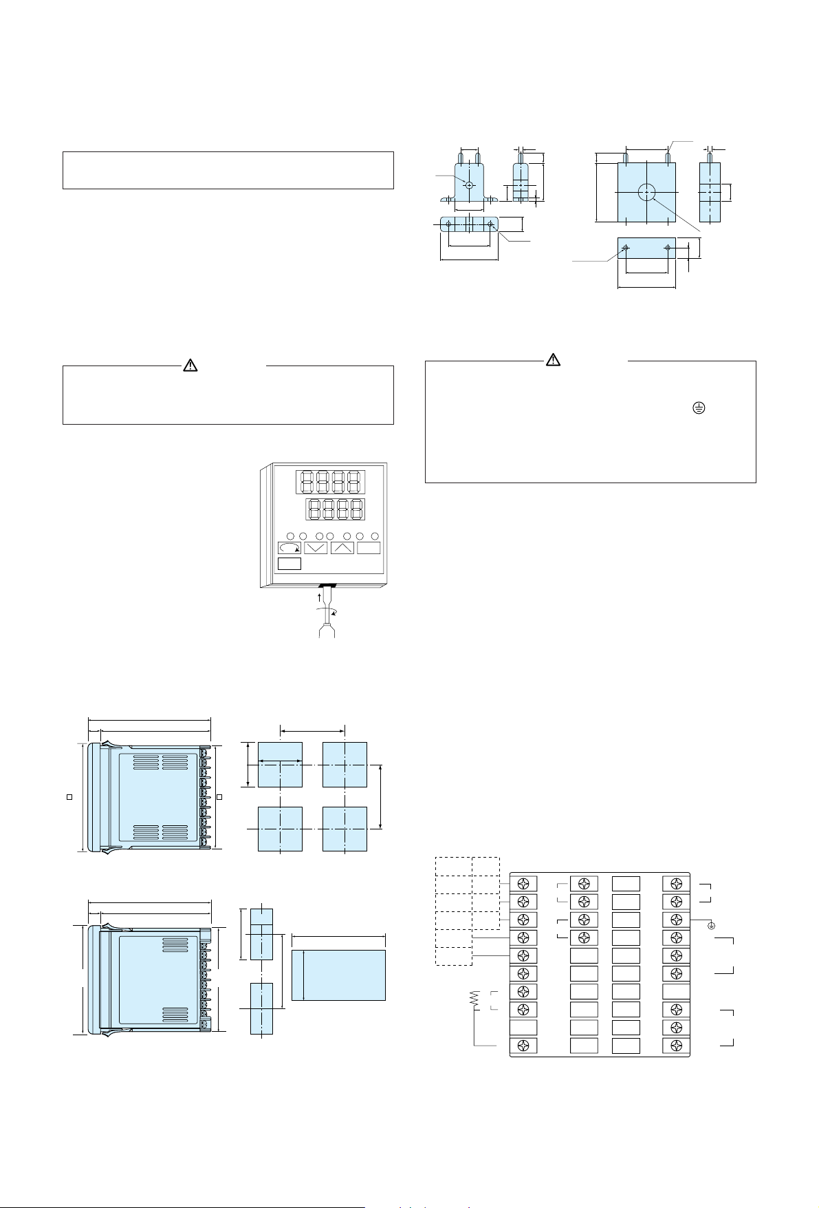
2-2.Mounting
(1) Machine the mounting hole by referring to panel cutout in
section 2-4.
(2) Applicable thickness of the mounting panel is from 1.0 to 3.5
mm.
(3) As this product provides mounting fixture, insert the product
from the front panel for installation.
2-3.How to remove the instrument out of the case
There is no need to remove your
SR73A and 74A series controllers out
of the case. Nevertheless, should the
need arise, for example, for
replacement, follow the steps
described below:
Insert a minus screwdriver of 6mm ~
9mm into the opening (where
packing is exposed) of the front case
and rotate the screwdriver while
pushing up the lock lever behind the
packing. Once the instrument comes
out by a few millimeters, you can
remove it by hand.
2-4.External dimensions and panel cutout
SR73A External dimensions SR73A Panel cutout
SR74A External dimensions SR74A Panel cutout
(unit : mm)
Note: The environmental conditions belong to the installation
category II of IEC 664 and the degree of pollution is 2.
When the instrument is removed/replaced in the case, make sure
the power is off. If it is done while the power is on, it may lead
to problems with the product and/or other problems.
ENT
MAN
PV
SV
˚C
OUT AT AH AH/HB MAN STBY COM
SHIMADEN
110
96 91.6
10010
130 min.
130 min.
92
+0.8
0
92
+0.8
0
110
10010
45
+0.6
0
(48 x N-3)
+1.0
0
92
+0.8
0
92
+0.8
0
130 min.
When N pieces are
installed laterally.
N= number
height 96
×
width 48
height 91.6
×
width 44.6
Dimension of current transformer (CT) for heater break
alarm
• For 0-30A (CTL-6-S)...................................For 0-50A (CTL-12-S36-8)
(unit : mm)
2-5.Wiring
(1) Wiring operation should be done according to the instruction
for the terminal arrangement in section 2-6. Exercise care
that no wrong connection is made.
(2) Crimp terminal should accommodate the M3.5 screw and
should have a width of less than 7mm.
(3) For thermocouple input, select the compensation wire
suitable to the thermocouple type.
(4) For R. T. D. input, leads should be less than 5Ω in resistance
and three leads should have the same resistance.
(5) Input signal line should be conducted safely apart from the
high voltage power line.
(6) Shield wiring (single point grounding) is effective for static
induction noise.
(7) Short interval twisted pair wire for input signal is effective
for electromagnetic induction noise.
(8) For power line, use wire or cable which is 1mm
2
or more in
sectional area and of which the performance is equal to or
higher than that of 600V vinyl insulated wire.
(9) Earth grounding should be performed with earth resistance
less than 100Ω and with wire thicker than 2mm
2
.
2-6.Terminal arrangement
SR73A
15
21
30
40
2.8
3
10.5
7.525
10
φ 5.8
2- φ 3.5
φ 12
φ 2.36
φ 12
940
15
7.5
2.3630
30
40
2-M3 depth 4
• Always disconnect this product from any power source
during wiring operation to prevent electrical shock.
• Be certain that the protective conductor terminal ( ) is
properly grounded. Otherwise, a serious electric shock may
result.
• Avoid touching the wired terminal and charged devices while
supplying power.
CAUTION
WARNING
422A 485
SG SG
SD+ +
SD– –
RD+
RD–
TC•mV
RTD
V•mA
IN PUT
1
2
3
4
5
6
7
+A
–B
8
9
B
10 20
21
SB
22
23
CT
24
25
26
27
28
29
30
31
32
33
34
35
36
37
38
39
40
L
11
12
13
14
15
16
17
18
19
N
COM+
NO –
NC
COM
AH
AL/HB
~
Power
CONTROL
OUTPUT
ALARM
OUTPUT
- 4 -
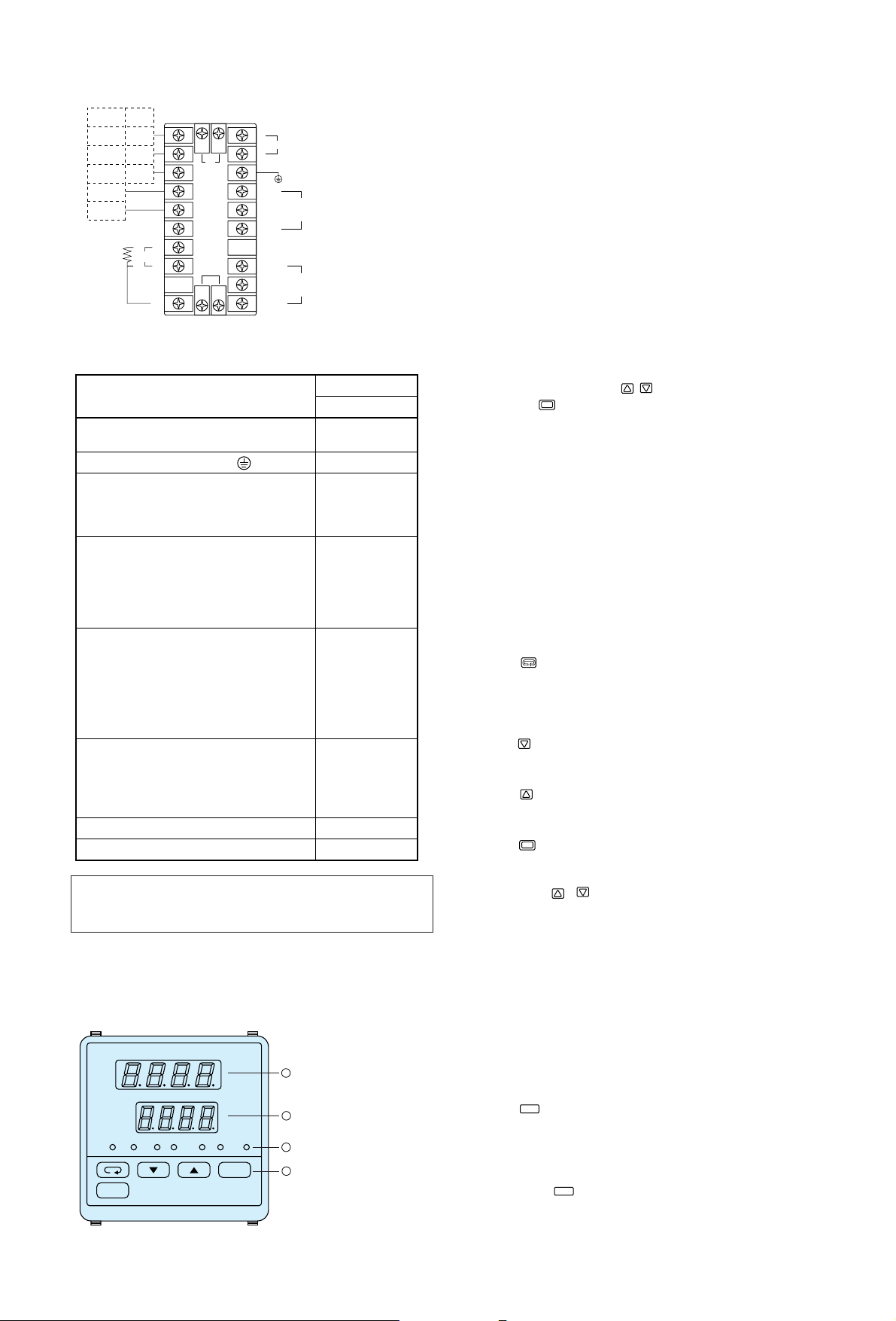
SR74A
2-7.Terminal arrangement table
3. Instruction for front panel
3-1. Drawing and the name of the parts
This is an example of the front panel of SR73A.
Name of parts
: Measured value
(PV) display
: Set value (SV)
display
: Monitor LED
: Key switches
10 20
23 24
19
18
17
16
15
14
13
12
2221
11
9
8
7
6
5
4
3
2
1
422A 485
RD–
RD+
SD– –
SD+ +
SG SG
L
N
COM+
NC
COM
AL/HR
AH
NO –
Power
CONTROL
OUTPUT
ALARM
OUTPUT
CT
SB
IN PUT
RTD
TC•mV
V•mA
+A
–B
B
~
Heater break alarm (option) CT input terminal
Name of terminal and description
Terminal number
SR73A and 74A
Power terminal
100-260V AC±10% 50/60Hz 12VA
Protective conductor terminal ( )
Input terminal
R. T. D. A, Thermocouple, Voltage, Current +
R. T. D. B, Thermocouple, Voltage, Current –
R. T. D. B
Output terminal
Contact: COM, SSR Drive voltage, Voltage,
Current +
Contact: NO, SSR Drive voltage, Voltage,
Current –
Contact: NC
Communication terminal
For RS-422A For RS-485
SG SG
SD+ +
SD– –
RD+
RD–
Alarm output (option) terminal
COM Contact rating 240V AC 1.5A
(resistive load)
AH Higher limit alarm
AL/HB Lower limit alarm or heater break alarm
Set value bias (option) input terminal
11-12
13
21-22
23-24
7
8
10
18
19
20
1
2
3
4
5
14
15
16
Note: For Thermocouple, Voltage, and Current input,
measurement error results by connection between B and
B terminal.
3-2. Instruction for front panel
: Measured value (PV) display (green)
(1) Displays current measured value on the mode 0 basic
screen.
(2) Displays parameter type on each parameter screen.
: Set value (SV) display (orange)
(1) Displays set value on the mode 0 basic screen.
(2) Displays selected item and set value on each parameter
screen.
: Monitor LED
(1) OUT (output) monitor LED (green)
• For contact or SSR drive voltage output, a light turns
on for output ON and turns off for output OFF.
• For current or voltage output, the light intensity
changes proportionally to the output altitude.
(2) AT (auto tuning) monitor LED (green)
• On selection by , ON turns on AT waiting
( key), flashes on AT execution.
(3) AH alarm output monitor LED (red)
• Turns on for higher limit alarm output ON.
(4) AL/HB alarm output monitor LED (red)
• Turns on for lower alarm output ON or heater break
alarm ON.
(5) MAN (manual control output) monitor LED (green)
• Flashes when control output is in manual operation.
(6) STBY (control output stop) monitor LED (green)
• Turns on when the control output stop mode is
selected.
(7) COM (communication) monitor LED (green)
• Turns on when the remote communication mode is
selected.
: Key switches
(1) (parameter) key
• Press on set screen to move to next set screen.
• Keep pressing three (3) seconds for function of move
key between basic screen of the mode 0 screen group
and direct call screen of mode 1 screen group.
(2) (down) key
• Press on the set screen to flash the point of the least
digit and to reduce data or back increment data.
(3) (up) key
• Press on the set screen to flash the point of the least
digit and to increase data of increment data.
(4) (entry/registration) key
• Press on the set screen of the mode 0 screen group
and mode 1 screen group to fix the data changed by
the , keys and to extinguish flash of the point.
• The function selecting screen, of the mode 2 screen
group, registers data of the point flashing digit and
simultaneously shifts a data changeable digit (the
point flashing digit).
• The input scaling screen, of the mode 2 screen group,
registers data and shifts a parameter capable of being
set (in the row in which the rightmost point is
flashing).
• Press the key for five seconds and it functions to
change the basic screen of the mode 0 screen group to
the function selecting screen of the mode 2 screen
group and vice versa.
(5) (manual) key
• Pressing this key on the control output screen changes
automatic control output to manual control output and
vice versa. During manual control output, the MAN
monitor LED flashes.
• The key does not function in the control output
stop mode.
ENT
MAN
ENT
MAN
PV
SV
OUT AT AH MAN STBY COMAH/HB
SHIMADEN
ENT
MAN
˚C
4
3
2
1
- 5 -
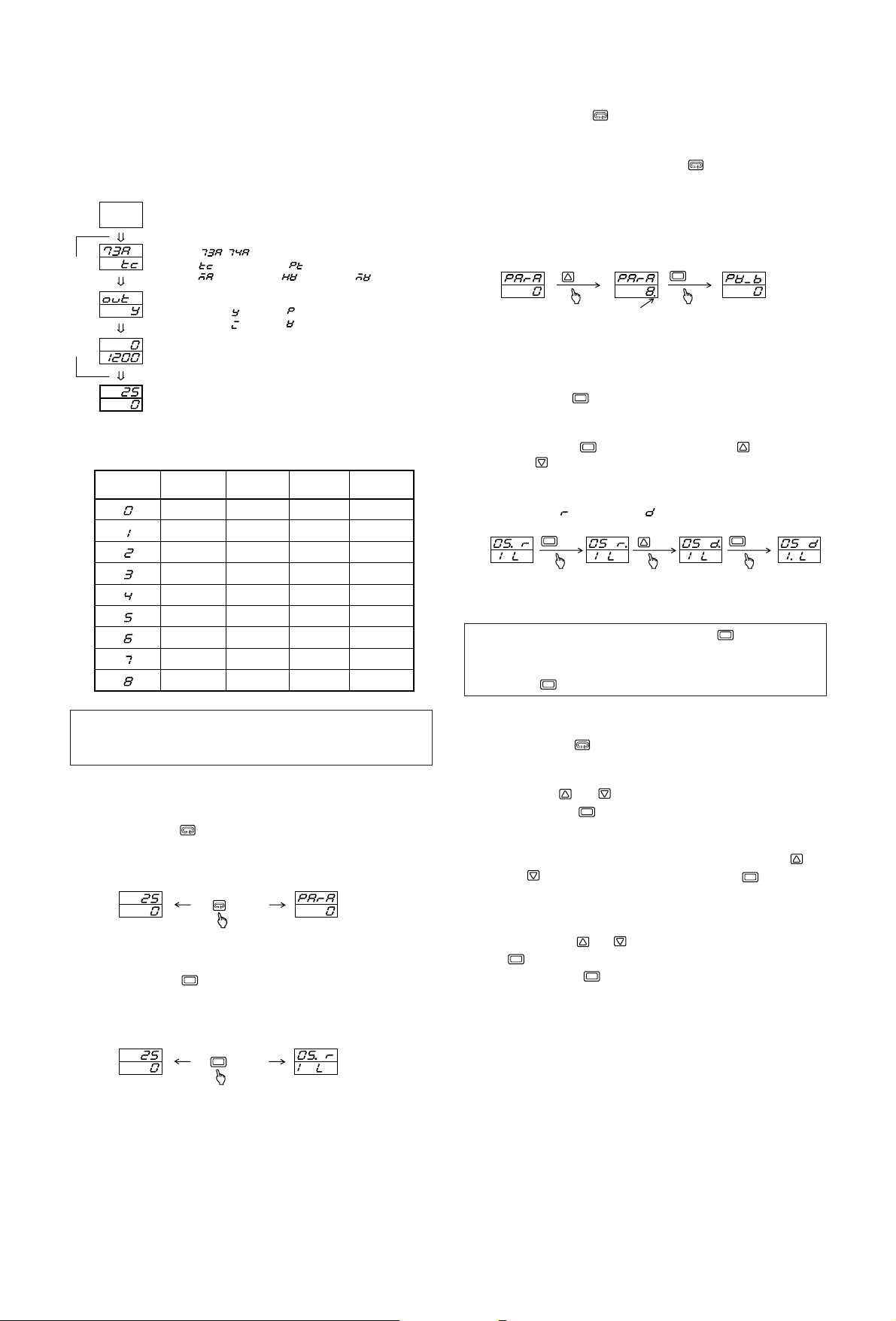
4. Screen instruction
4-1. Power on and initial screen display
After turning on power, the display shows each power on initial
screen for approx. 1.5 seconds, then moves into the basic screen
of the mode 0 screen group.
4-2.Alarm type code table
4-3.Screen change
(1) Screen change from mode 0 group to mode 1 group
• Pressing the key for three seconds on the basic screen
of the mode 0 screen group changes it to the direct call
screen of the mode 1 screen group and vice versa.
(2) Screen change from mode 0 group to mode 2 screen group
• Pressing the key for five seconds on the basic screen
of the mode 0 screen group changes it to the function
selecting screen of the mode 2 screen group and vice versa.
Measured value (PV)
Set value (SV)
Turning
on power
Series type ( )
,
Input type ( : Thermocouple, : R. T. D.,
Control output type : Contact : SSR drive voltage
: Current : Voltage
Lower limit of the selected measuring range
Higher limit of the selected measuring range
Power on initial screen
: Voltage (mV), : Voltage (V), : Current (mA))
Displays output screen
Mode 0 screen group basic screen
(3) Screen change within mode 0 screen group
• By pressing the key, the screen changes.
(4) Screen change within mode 1 screen group
• Two methods are used for screen change within mode 1
screen group. One is to press the key as shown on
above mode 0 screen group. The other is to mode the
screen directly by indicating screen No. on the top direct
call screen.
Example: Direct calling the screen No.8 PV bias value set
screen
(5) Selecting and setting digit to change of function selecting
screen of mode 2 screen group
• When the function selecting screen is displayed, the point
of selectable digit flashes.
• By pressing key, the selectable digit (digit whose
point is flashing) moves.
• In case of changing the set value, flash the point to be
changed with key, select data with the keys and
press key again to register the set value and move
selectable digit.
Example: changing the control output characteristics from
(heating) to (cooling)
* “.” on the screen shows the selectable digit (digit whose
point is flashing).
(6) Shifting setting items on input scaling screen of mode 2
screen group and setting method
• Pressing the key on the function selecting screen calls
the input scaling screen onto the display. The decimal
point in the rightmost position on the top row flashes.
Press the or key to change the lower limit value
and press the key to register the data.
• Upon registering the lower limit value data, the decimal
point in the rightmost digit in the bottom row begins to
flash. Change the higher limit value by pressing the
or key and register it by means of the key.
• Upon registering the higher limit value data, the decimal
points in the rightmost digits of the bottom and top rows
flash. Change the positions of the decimal points by
pressing the or key and register it by means of the
key.
• Each time the key is pressed, the flashing decimal
point in the rightmost digit moves from the top row→
bottom row→top and bottom rows→top row→.
• In case the lower limit value and the higher limit value are
set to produce a difference which is less than 100 counts or
more than 5000 counts, the higher limit value is forced to
change to +100 or +5000 counts. The higher limit cannot
be set to be less than a lower limit value +100 counts or
more than a lower limit value +5000 counts.
Alarm code
0 ( )
1 ( )
2 ( )
3 ( )
4 ( )
5 ( )
6 ( )
7 ( )
8 ( )
AH
assignment
Not assigned
Higher limit
deviation value
Higher limit
absolute value
Not assigned
Lower limit
deviation value
Lower limit
absolute value
Lower limit
deviation value
Lower limit
absolute value
Higher limit
deviation value
Higher limit
absolute value
Higher limit
deviation value
Higher limit
absolute value
Higher limit
deviation value
Higher limit
absolute value
With/Without
inhibit action
Without
inhibit action
Without
inhibit action
With
inhibit action
With
inhibit action
Without
inhibit action
Without
inhibit action
With
inhibit action
With
inhibit action
Without
inhibit action
Without
inhibit action
With
inhibit action
With
inhibit action
– – – – –
With/Without
inhibit action
– – – – –
– – – – –
– – – – –
– – – – –
– – – – –
AL/HB
assignment
Heater break
Heater break
Heater break
Heater break
Note: In the above table, the alarm codes 5 through 8 are
selectable when the apparatus has the optional function
of heater break alarm.
Note: In case of changing data and pressing key longer
than 5 seconds, the screen moves to mode 0 basic screen
without a data registration. It requires a data verification
with key and screen change.
1-0 direct call screen 1-0 direct call screen 1-8 PV bias value set screen
key
ENT
key
0-0 Basic Screen 1-0 direct call screen
key
3 seconds
ENT
0-0 Basic Screen 2-0 Function selecting screen
ENT
key
5 seconds
several times
point flashes
ENT
ENT
ENT
key
key
ENT
ENT
ENT
ENT
ENT
ENT
key
ENT
 Loading...