

Shimaden GAT10-DN Instruction Manual
GAT10-DNT-1BE
May. 2016
GAT10-DN
RS-485/DeviceNet Converter
Instruction Manual
Basic Part
Thank you for purchasing our product. Please check that the delivered product is
the item exactly as ordered by you. Please read this manual thoroughly to
understand the contents before you start operating the product.
Please ensure that this instruction manual is given to the end user.
For details of the operation and parameters of Shimaden instruments to be connected to the
GAT10-DN, please refer to the instruction manual and communication interface instruction
manual of the instrument.
This instruction manual is meant for persons involved in wiring, installation, operation and
routine maintenance for the GAT10-DN. It describes matters to be attended to in handling
it, how to install it, wiring for it, its functions and operating procedure. It is requested that
for ready reference, this manual is kept at the work site where the GAT10-DN is used.
In operating it, please follow the instructions contained herein.
This instruction manual describes matters to be attended to concerning safety, potential damage
to equipment and/or facilities, additional explanations and notes under the following headings:
" Warning" ◎This heading indicates that failure to follow instructions could cause injury or
even death.
" Caution" ◎This heading indicates that failure to follow instructions could cause damage
to equipment and/or facilities.
"Note" ◎This heading indicates additional explanations or notes.
The safety rules apply only to this product. For those as a PLC system, please refer to the User's
Manual of PLC Unit.
The GAT10-DN is designed for general industrial use. Therefore, it should not be used in any
way that might result in injury or fatality, or must be used only after adequate safety measures
are taken. No responsibility will be taken for any accident resulting from the usage of this
product without appropriate safety measures being in place.
● The GAT10-DN must be housed in a control box or the like to prevent the terminal board
from coming into accidental physical contact with personnel.
● The GAT10-DN should not be taken out of the case. If your hand or an electric conductor is
put inside it, an electric shock may result in serious injury or even death.
● Make sure that the protective conductor terminal is grounded.
If there is any possibility of doing harm or damage to peripheral devices, equipment or
products, you must take appropriate safety measures such as installing the proper fuse or an
overheating prevention device before you start using the GAT10-DN. No responsibility will be
taken for any accident resulting from the usage of this product without appropriate safety
measures being in place.
● As means to turn the power off, a switch or a breaker should be installed in the external
power circuit to be connected to the power supply terminal of the GAT10-DN. The switch
or the breaker should be installed adjacently to the GAT10-DN and in a position which
allows it to be operated easily, with an indication that it is a means of disconnecting the
GAT10-DN from its power source. The switch or the breaker should meet the GAT10-DN
requirements of IEC60947.
● Fuse:
The instrument has no built-in fuse. Ensure to install a fuse in the power circuit to be
connected to the power supply terminal. The fuse should be placed between the GAT10-DN
and the switch or the breaker.
Fuse Rating/Characteristic: 250VAC 0.5A/ In the case of a medium time-lagged or timelagged type switch, one which meets the requirements of IEC60127 should be used.
● Make sure that a draft hole should not be blocked and that it should be protected from dust
and dirt. Failure to do so might cause fire or faulty operations.
● Do not repeat endurance tests for voltage, noise, surging and the like. Doing so might cause
fire or faulty operation.
● Do not attempt to disassemble, repair, or modify the GAT10-DN. Doing so might cause fire
or faulty operation.
1. Safety Rules
Caution
● Control lines and communication cables should not be bundled with the main power circuit
or the power line, or installed adjacently. They should be spaced apart by more than 100 mm
as a guideline. Failure to do so might cause faulty operation.
This instruction manual: 1 Connector : 1
Mounting base :
1
Note: If you find a problem with the product or some of the attached items missing, please
contact our sales agent.
■ Checking Attached Items
Avoid installing the GAT10-DN in the following locations. Failure to do so might cause fire or
faulty operations.
● Where flaming gas, corrosive gas, soot, or particles that can deteriorate electrical insulation
is generated or is abundant.
● Where ambient temperature lowers below -10℃ or exceeds 50℃.
● Where relative humidity exceeds 90%RH or falls below dew point.
● Where highly intense vibration or impact is generated.
● Near high voltage power lines or where inductive interference can affect the operation of
the product.
● Where the product is exposed to direct sunlight, wind or rain.
● Where the elevation exceeds 2,000 m.
● Where the product is directly exposed to the flow of emitted air.
■ Installation Site
Caution
In wiring, close attention should be paid to the following.
● Always disconnect the GAT10-DN from any power source during wiring operation to
prevent an electric shock.
● Make sure that the protective conductor terminal is grounded properly. Failure to do so
might cause electric shock.
● Don't touch the wired terminals and charged devices while the instrument is energized.
Doing so might cause electric shock.
■ Wiring
Caution
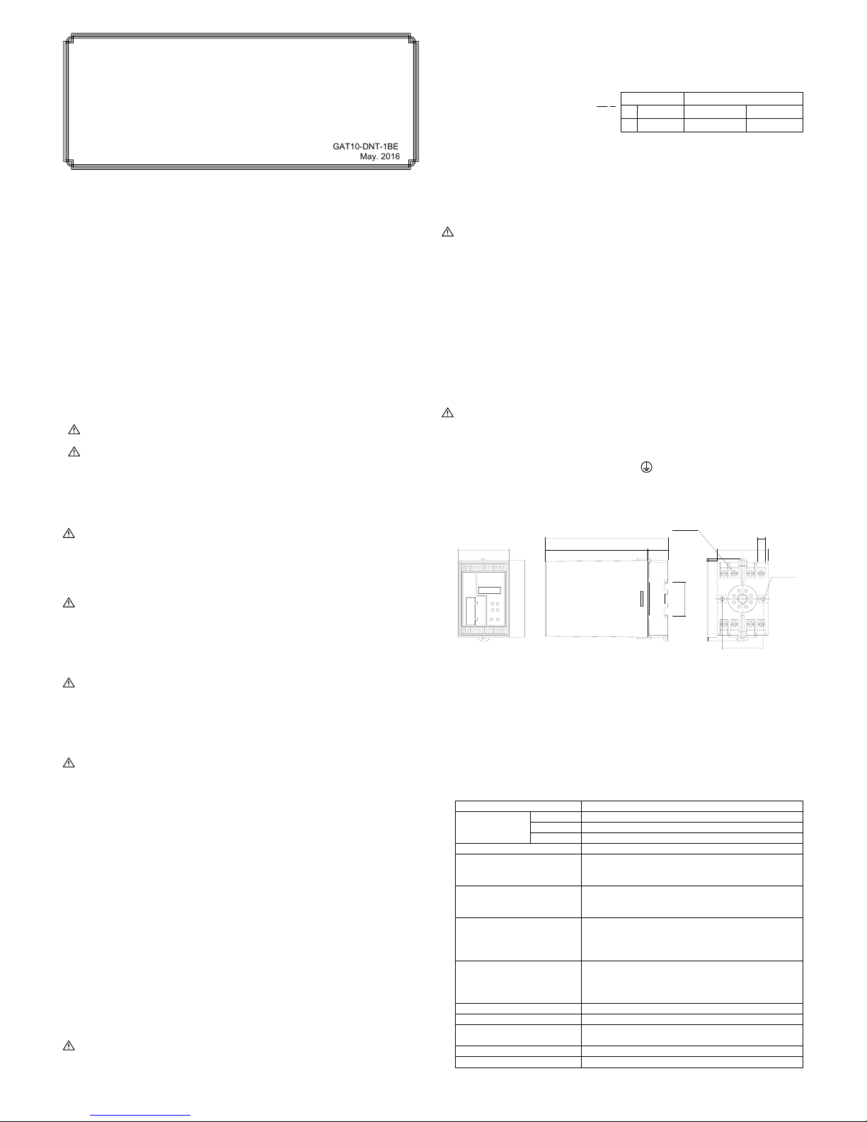
■ External Dimensions
This is the "Basic" Part of the instruction manual. Please also read the "Design" Part, which
you can download from our website. (URL http://www.shimaden.co.jp)
● The GAT10-DN enables writing and reading, from the DeviceNet, of Measured values,
Target set values and parameters for up to 8 Shimaden instruments with RS-485
communication.
● The GAT10-DN is connectable to the following Shimaden products:
Digital controllers : SR80 series, SR90 series, SR253
Program controller: FP93
Digital indicator : SD16
Servo controller : EM70
3. Specifications
Item
Supply voltage
■ General Specifications
Power consumption
Insulation resistance
Dielectric strength
Mounting
Mass
Temperature
Humidity
Storage temperature
Approx. 250g(Including base)
DIN rail or screw
Specifications
100~240V AC±10% 50/60Hz
24V AC±10% 50/60Hz
24V DC±10%
-10~50℃
90%RH or less(no dew condensation)
2. Preliminary Steps
Please confirm that the delivered product is exactly as you specified by comparing the
model codes pasted on the case of the GAT10-DN with the following codes.
Example of model code
:
GAT10-DN-90-0
■ Confirmation of Specification Codes
①②
Ambient conditions
for operation
-20~65℃
5VA(100~240V AC)
4VA(24V AC)
3W (24V DC)
Between input/output terminals and power terminal 2300V AC 1
minute (induction current: 3mA)
Between power terminal and protective conductor terminal
1500V AC 1 minute (induction current: 3mA)
Between input/output terminals and power terminal 500V DC
20MΩ min.
Between input/output terminals and protective conductor
terminal 500V DC 20MΩ min.
Material of case
Color of case
External dimensions
PPO resin molding
H80xW50xD120 mm(Including base, but excluding front
connector)
Black
Altitude 2000 m from the sea level or lower
Caution
Caution
Warning
Warning
Code and DescriptionItem
①②Power supply
Special note
90: 100-240V AC
0: Without
08: 24V AC/DC
9: With
100
120
50
80
8-M3.5×7
20
(2)
7.8
±0.2
51 min.
(4)
35.4
81 min.
2-φ4.5
(Unit mm)
40
±0.2

No. 2
CableColor and Signal Connector
GAT10-DN
■ DeviceNet Specifications
Transmission rate
125k bps
250k bps
500k bps
Setting not allowed
● DeviceNet transmission rate setup
■ RS-485 (Shimaden standard protocol) Specifications
Specifications
EIA RS-485 compliant
2-line half duplex multidrop
Start-stop synchronization
Max. 500 m
19200 bps
7 bit/even parity/1 stop bit
Max. 8
SR80 series, SR90 series, SR253, SD16, EM70, FP93
Approx. 1.5 sec
(when 8 Shimaden units are connected and without SV
value updating, and parameter reading/writing)
Terminal arrangement
● Use the special cable for DeviceNet.
● Use the attached connector.
● The connector is equivalent to the MTB2, 5/5-ST-5. 08 ABGYAU made by PHOE NIX CONTACT.
● For grounding and terminating resistor for DeviceNet, refer to the DeviceNet Specification s published by
ODVA.
4. Wiring
■ Connecting DeviceNet communications
Item
Signal level
Communication method
Synchronization method
Communication distance
Communication rate
Data format
Number of connectable
Shimaden instrument
Connectable products
Scan time
■ Connecting RS-485 communications
RS-485
Power supply
Terminating resistor
(attached to the instrument)
Shimaden instruments
No particular maintenance is required for the GAT10-DN. Check the inspection items listed in Master
PLC User's Manual so that your system can always be used in optimal conditions.
■ Maintenance
● The external line should not be bundled with or installed adjacently to a load line except tho se from
the main power circuit line, a high voltage line and the PLC. Otherwise it will easily be affected by
noise, surge or induction.
● For a shielding wire or a shielded cable, one-point grounding on the PLC side is required . Depending
on the condition of external noise, however, it may be better to ground on the externa l side.
1 to 8Local address
Connector
Network current consumption
Special cable for DeviceNet
125k bps 500k bps250k bps
500 m 100 m250 m
Specifications
Master/slave system
CAN Protocol
Trunk line, Drop line
125k/250k/500k bps
Fixed to 24 words each for input and output
0~63
Communication adaptor
Accessories
40mA max.
Item
Communication system
Protocol
Type of transmission line
Type of device
Occupied word count
Node address
Maximum transmission
distance
Connecting cable
Transmission rate
SW6
OFF
ON
OFF
ON
SW7
OFF
OFF
ON
ON
● DeviceNet Node Address Setup
NA0Address
0
1
・・・
62
63
NA5NA4NA3NA2NA1
OFF OFF OFF OFFOFFOFF
ON OFF OFF OFFOFFOFF
OFF ON ON ONONON
・・ ・・ ・・ ・・・・・・
ON ON ON ONONON
2 ON ON OFF OFFOFFOFF
■ External Wiring
As one of the requirements for enabling the GAT10-DN to function thoroughly and to establish a
highly reliable system, external wiring that is not easily affected by noise is necessary. The following
are matters to be attended to for external wiring.
Signal
V
-
CAN_L
Drain
CAN_H
V +
Color
Black
Blue
----
White
Red
The GAT10-DN has a built-in RS-485 terminating resistor. To the Shimaden instrument as the final
station, attach the terminating resistor supplied as an accessory to it. However, please attach the
terminating resistor to only one instrument (final station). If attached to two or more i nstruments,
correct operation cannot be guaranteed.
Note: No devices except Shimaden instruments should be connected to the RS-485 line. Otherwis e,
correct operation cannot be guaranteed.
Note: Make sure to use GAT10-DN as a terminal station of RS-485 communications.
■ Terminating resistor
● DeviceNet
● RS-485
Install the DeviceNet terminating resistor according to the Master PLC Instruction Manual and the
DeviceNet Specifications issued by ODVA.
Transmission rate
Total length
GAT10-DN
SHIMADEN
POWERRESET
MS NS
RX TX
LED indicating operating status of DeviceNet
LED indicating operating status of RS-485
communication
Reset switch
Switch for transmission rate setup
( SW6, SW7 )
Note: Set values become effective upon applying power or resetting.
DeviceNet
connector
V-
CAN_L
CAN_H
Drain
V+
Switch for node address setup
( NA0~NA5 )
Lights "green" when GAT10-DN
operates normally. In other displays,
setting error/device error has occurred.
Name Color Function Remarks
MS
Green/
Red
Module status
(DeviceNet)
Lights "green" when GAT10-DN is online. In other displays, communication
failure/connection error has occurred.
NS
Green/
Red
Network status
(Device Net)
Lights during reception of data
TX Green
RS-485
Data transmission
Lights during transmission of data
RX Green
RS-485
Data receipt
● LED indicating operating status
V -
CAN_L
Drain
CAN_H
V +
V -
CAN_L
Drain
CAN_H
V +
Name of SignalNo.
①
②
③
④
⑤
⑥
⑦
⑧
RS-485 :
-
RS-485 : +
NC
Power supply: N
Power supply: L
Power supply: FG
RS-485 : SG
NC
L
N
⑤
⑥
⑦⑧
④
③
②
①
・
・
・
No. 1
+
-
SG
+
-
SG
No. N
(the final station)
+
-
SG
The contents of this manual are subject to change without notice.
Temperature and Humidity Control Specialists
Head Office: 2-30-10 Kitamachi, Nerima-Ku, Tokyo 179-0081 Japan
Phone: +81-3-3931-7891 Fax: +81-3-3931-3089
E-MAIL: exp-dept@shimaden.co.jp URL: http://www.shimaden.co.jp
PRINTED IN JAPAN
 Loading...