

Shimaden EM51 series Instruction Manual
EM51 Series
Plug-in Type Servo Controller
Instruction Manual
Thank you for purchasing our product.
Check that the delivered product is the correct item you ordered.
Do not begin operating this product until you have read and
thoroughly understood the contents of this Instruction Manual.
EM51F2CE
Dec. 2010
Notice: Make sure that this Instruction Manual is given to the final user of the device.
Preface: This Instruction Manual is meant for persons involved in wiring, installation, operation and routine maintenance
of the EM51 Series. It describes matters to be attended to in handling the EM51 Series, how to install it and its wiring.
It is requested that for ready reference, this manual is kept at the work site during operation of the EM51 Series.
In operating it, please follow the instructions contained herein.
This Instruction Manual describes matters to be attended to concerning safety, potential damage to equipment
and/or facilities, additional explanations and notes under the following headings.
WARNING: This heading indicates that failure to follow instructions could cause injury or even death.
CAUTION: This heading indicates that failure to follow instructions could cause damage to equipment and/or facilities.
The EM51 Series Servo Controller is designed for controlling
temperature, humidity and other physical quantities in general
industrial facilities. Therefore, it should not be used in any way
that might result in injury or fatality, or must be used only after
adequate safety measures are taken. No responsibility will be
taken for any accident resulting from the usage of this device
without appropriate safety measures being in place.
•
This device must be housed, for example, in a control box to
prevent the terminal board from coming into accidental physical contact with personnel.
•
To prevent electric shock, always turn off and disconnect this
device from the power supply before starting wiring.
•
Do not touch wired terminals or charged parts with your hands
while the power is supplied.
To avoid damage to connected peripheral devices, facilities or
the product itself due to malfunction of this device, safety countermeasures such as proper installation of the fuse or installation
of overheating protection must be taken before use. No responsibility will be taken for any accident resulting from the usage
of this device without appropriate safety measures being in
place.
•
The Alert Symbol Mark on the plate affixed to this device:
The Alert Symbol Mark indicated on the nameplate affixed
on the casing of this device warns you not to touch charged
parts while this device is powered ON. Doing so might cause
an electric shock.
•
A means for turning the power OFF such as a switch or a
breaker must be installed on the external power circuit connected to the power supply terminal on this device.
Fasten the switch or breaker at a position where it can be easily operated by the operator, and indicate that it is a means
for powering this device OFF.
•
Use this device by ensuring the wire connection part is firmly tightened.
•
Fuse: This device has no built-in fuse. Ensure to install a fuse
in the power circuit to be connected to the power supply terminal.
Fuse rating/characteristic: 250V AC 0.5A
•
Use the device with the power voltage, frequency, load current
and voltage within their rated ranges.
•
Use the device with the relay contact current only within its
rated range. When using with any motor, use only within
approx. 1/5 of the rated range since inrush current or surge
voltage may occur.
•
Users are prohibited from remodeling this device or using it
in a prohibited or unauthorized manner.
WARNING
CAUTION
1. Specification
Input ............................................See ordering information.
Feedback Resistance ...................100Ω ~ 2kΩ randam/3-wire
Output .........................................Relay contact or Triac (SSR)
Output Rating/Contact Protection
Relay contact..........................240V AC, 1A (inductive load)/
CR Absorber
Triac (SSR) ............................
20 ~ 120V AC, 1A (inductive load)/
CR Absorber + varistor
Hysteresis...................................
Approx. 0.5% fixed of input signal range
Deadband (DB) ...........................
1 ~ 10% variable of input signal range
Dead Time...................................Approx. 0.2 sec.
(Chattering prevention)
Zero & Span Adjustment ............0% (ZERO): 0 ~ 20% variable
100% (SPAN): 70 ~ 100% variable
Output Action Display ................M2-M1/LED green lighting
M2-M3/LED red lighting
Operating Ambient Temperature
.....-10 ~ +50°C
Operating Ambient Humidity ....
.
90% RH max. (no dew condensation)
Storage Temperature...................-20 ~ 65°C
Power Supply..............................See ordering information.
Power Consumptio
n....................Approx. 4 VA
Insulation Resistance
Between the input and power supply terminals: 500V DC, 100MΩ min.
Between the output and power supply terminals:
500V DC, 100MΩ
min.
Dielectric Strength
Between the output and power supply terminals: 1 min. at 1000V AC
Material.......................................ABS resin molding
External Dimension
s...................80 (H)
x
50 (W) x130 (D) mm
Installatio
n ..................................11P Plug-in
Weigh
t.........................................Approx. 350g
(Exclusively used for AC load)
2. Ordering Information
ITEMS CODE SPECIFICATIONS
1. SERIES
EM51- Plug-in type servo controller
1
1 ~ 5mA DC, Receiving Impedance
: 250Ω
2
4 ~ 20mA DC, Receiving Impedance
: 62Ω
2. INPUT 3 0 ~ 10V DC, Input Resistance:200kΩ
5 Potentiometer 100Ω ~ 2kΩ, 3-wire type
9 Others (Please consult before ordering.)
Y
Contact 240V AC, 1A (inductive load)/
with CR Absorber
3. OUTPUT
R
Contact
240V AC, 1A (inductive load)/
without CR Absorber
S
Triac 20 ~ 120V AC, 1A (inductive load)
(Motor Supply Voltage: 20 ~ 120V AC)
13-
100 ~ 110V AC ±10%, 50/60Hz
14-
110 ~ 120V AC ±10%, 50/60Hz
4. POWER SUPPLY 15-
200 ~ 220V AC ±10%, 50/60Hz
16-
220 ~ 240V AC ±10%, 50/60Hz
99-
Others (Please consult before ordering.)
5. REMARKS
0 Without
9
With (Please consult before ordering.)
5. Terminal Arrangement
3. Installations
Do not use this device in the following sites to avoid any trouble since
us
e in such circumstances may generate severe harmful influence on
its performa
nce or its useful life, or lead to other shortcomings:
1. Locations that are filled with or generate corrosive gas or inflammable gas
2. Locations where high temperature/humidity is present
3. Locations where direct sunlight or radiant heat such as that from
an electric furnace is present
4. Locations where any vibration or shock may be experienced
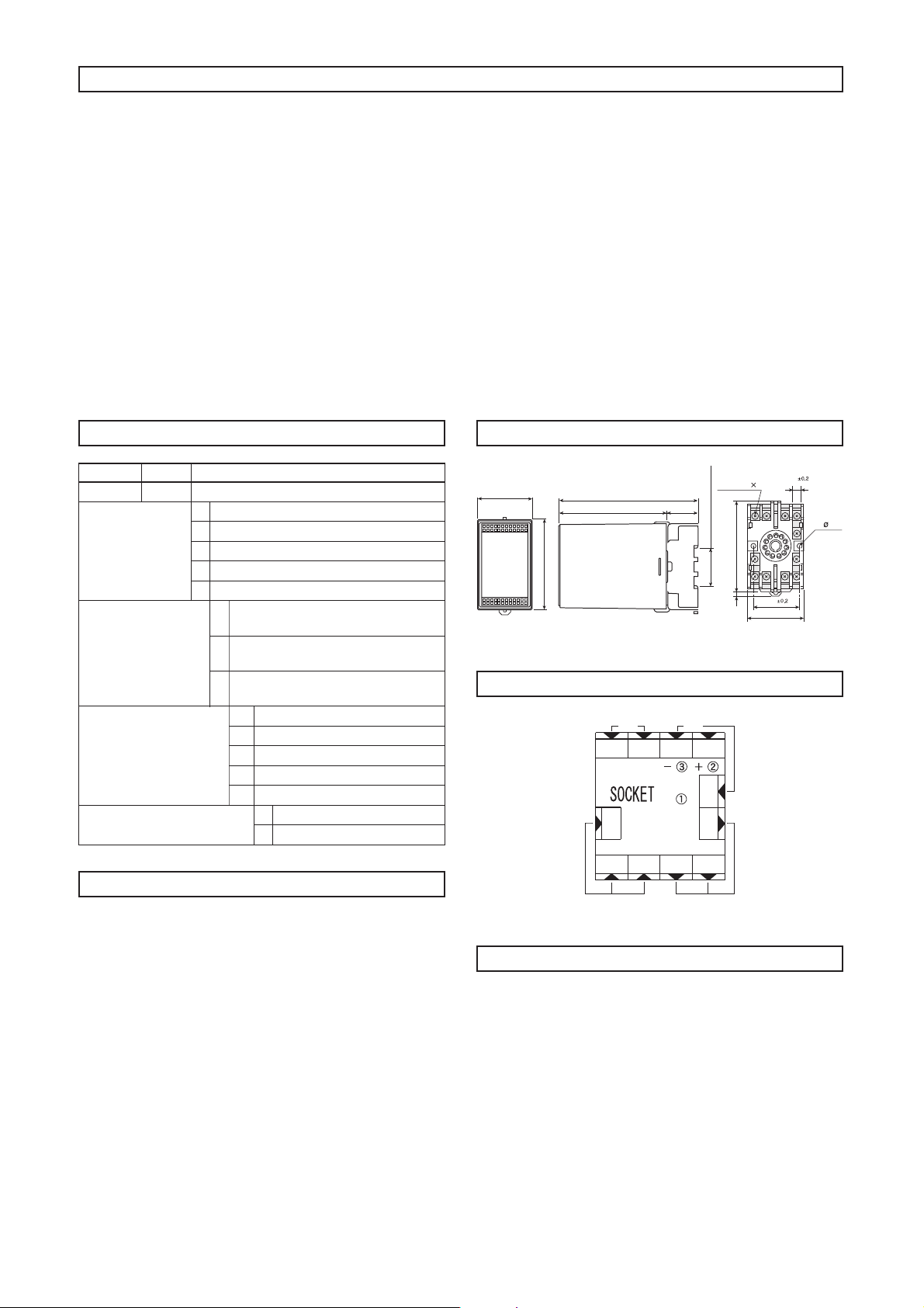
4. External Dimensions & Panel Cutout
6. Wiring
1. Wiring should be routed according to the indications located on
the terminal face plates.
Do
not apply too much force when tightening the terminal screw.
2. Keep wiring away from strong electrolyte circuits, or use shielding
wire to protect the feedback resistance wire from the input
signal/control motor.
3. If you inadvertently connect the motor power supply to the feedback
resistance circuit of the control motor, the potentiometer will
burn.
4. Connection terminal symbols found on control motors may vary
depending
on their manufacturer. Refer to the instruction man-
ual supplied by the manufacturer in question for clarification.
50
08
4.53
.xam 18
7.8
51 max.
130
10
0 30
11-M3.5 7
d
et
n
uom e
b
ot
l
i
ar
eh
t tif oT
Unit: mm
40
2- 4.5
8 7 6 5
4
3
10911 1 2
V U
R2
R1
R3 M1 M2
M3
Feed-Back
Potentiometer
MOTOR
POWER INPUT
Potentiomerer
4
 Loading...