

Page 1

Page 2
Safety Precautions
Shield M10U user manual I
Safety Precautions
This manual contains information concerning the installation and operation of Modular UPS. Please carefully read this
manual prior to installation.
The Modular UPS cannot be put into operation until it is commissioned by engineers approved by the manufacturer (or
its agent). Not doing so could result in personnel safety risk, equipment malfunction and invalidation of warranty.
The UPS has been designed for commercial or industrial use only, and is not intended for use in any life support
application. This is a CLASS C Uninterruptible Power Supply (UPS) product. In a domestic environment, this product may
cause radio interference, in which case, the user may be required to take additional measures.
Conformity and standards
This product complies with CE73/23 & 93/68 (low voltage safety) and 89/336 (EMC), and the following UPS product
standards:
*IEC62040-1-1-General and safety requirements for use in operator access area
*IEC/EN62040-2 EMC requirements CLASS C
*IEC62040-3 Performance requirements and test methods
For more details, refer to Chapter 9 . Continued compliance requires installation in accordance with these
instructions and the use of manufacturer approved accessories only.
WARNING: high earth leakage current
Earth connection is critical before connecting the input supply (include both utility supply and battery).
"Earth leakage current introduced by the UPS, in any configuration from 10kW to 150kW, exceeds 3.5 mA and is less
than 1000 mA and complies with the requirements of IEC/EN 62040-1 / IEC/EN 60950-1" Transient and steady-state
earth leakage currents, which may occur when starting the equipment, should be taken into account when selecting
instantaneous RCCB or RCD devices.
Residual Current Circuit Breakers ( RCCBs) must be selected sensitive to DC unidirectional pulses (class A) and
insensitive to transient current pulses.
Note also that the earth leakage currents of the load will be carried by this RCCB or RCD.
This equipment must be earthed in accordance with local electrical authority codes of practice.
WARNING: backfeeding protection
This system has a control signal available for use with an automatic device, externally located, to protect against
backfeeding voltage through the mains Static Bypass circuit. If this protection is not used with the switchgear that
is used to isolate the bypass circuit, a label must be added to the switchgear to advise service personnel that the
circuit is connected to a UPS system.
The text has the following meaning or is equivalent to: Isolate the UPS before working on the circuit of this UPS.
Components that can be maintained by user
All the equipment maintenance and servicing procedures involving internal access need special tools and should be
carried out only by trained personnel. The components that can only be accessed by opening the protective cover
with tools cannot be maintained by user.
This UPS full complies with “IEC62040-1-1-General and safety requirements for use in operator access area UPS”.
Dangerous voltages are present within the battery box. However, the risk of contactor with these high voltages is
minimized for non-service personnel. Since the component with dangerous voltage can only be touched by opening
the protective cover with a tool, the possibility of touching high voltage component is minimized. No risk exists to
any personnel when operating the equipment in the normal manner, following the recommended operating
procedures in this manual.
警告
危险
警告
危险
警告
危险
警告
危险
Page 3

Safety Precautions
II Rack Modular UPS System 10-90kVA User Manual
Battery voltage higher than 400Vdc
All the battery maintenance and servicing procedures involving internal access need special tools or keys and should
be carried out only by trained personnel.
SPECIAL CARE SHOULD BE TAKEN WHEN WORKING WITH THE BATTERIES ASSOCIATED WITH THIS EQUIPMENT.
WHEN CONNECTED TOGETHER, THE BATTERY TERMINAL VOLTAGE WILL EXCEED 400Vdc AND IS POTENTIALLY
LEATHAL.
Battery manufacturers supply details of the necessary precautions to be observed when working on, or in the vicinity
of, a large bank of battery cells. These precautions should be followed implicitly at all times. Particular attention
should be paid to the recommendations concerning local environmental conditions and the provision of protective
clothing, first aid and fire-fighting facilities.
警告
危险
Page 4

Contents
Shield M10U user manual III
Contents
Safety Precautions .................................................................................................................................
Chapter 1 Installation .......................................................................................................................... 1
1.1 Introduction ............................................................................................................................ 1
1.2 Initial Checking ....................................................................................................................... 1
1.3 Location ................................................................................................................................... 1
1.3.1 UPS Location ............................................................................................................... 1
1.3.2 External Battery Room .............................................................................................. 2
1.3.3 Storing .......................................................................................................................... 2
1.4 Positioning .............................................................................................................................. 2
1.4.1 System Cabinet ........................................................................................................... 2
1.4.2 Moving the Cabinets .................................................................................................. 3
1.4.3 Clearances Required for Operating ........................................................................ 3
1.4.4 Front Access ................................................................................................................ 3
1.4.5 Final Positioning ......................................................................................................... 3
1.4.6 Installation of Adjustable Feet ................................................................................. 3
1.4.7 UPS Composition ........................................................................................................ 3
1.4.8 Installing Power Modules ......................................................................................... 5
1.4.9 Cable Entry .................................................................................................................. 7
1.5 External Protective Devices................................................................................................. 8
1.5.1 Rectifier and Bypass Input Supply of the UPS ....................................................... 8
1.5.2 External Battery ......................................................................................................... 9
1.5.3 UPS Output.................................................................................................................. 9
1.6 Power Cables .......................................................................................................................... 9
1.6.1 Cable Connections ................................................................................................... 10
1.7 Control Cabling and Communication ............................................................................... 11
1.7.1 UPS Dry Contactor and Monitoring Board Features .......................................... 11
1.7.2 Dry Contactor Interface of Battery and Environmental Temperature Detection
............................................................................................................................................... 12
1.7.3 Remote EPO Input Port ........................................................................................... 12
1.7.4 Generator Input Dry Contactor .............................................................................. 13
1.7.5 BCB Input Port .......................................................................................................... 14
1.7.6 Battery Warning Output Dry Contactor Interface .............................................. 14
1.7.7 Integrated Warning Output Dry Contactor Interface ........................................ 15
1.7.8 Mains Failure Warning Output Dry Contactor Interface .................................... 15
Chapter 2 Battery Installation and Maintenance ......................................................................... 17
2.1 General Recommendations ............................................................................................... 17
2.2 Battery Typologies .............................................................................................................. 18
2.2.1 Traditional Battery Installation .............................................................................. 18
2.3 Battery Maintenance .......................................................................................................... 19
Chapter 3 Installation of UPS Rack System ................................................................................... 20
3.1 Overview ............................................................................................................................... 20
3.2 UPS Rack Modules in Parallel System .............................................................................. 21
3.2.1 Installation of Cabinet ............................................................................................. 21
3.2.2 External Protective Devices ................................................................................... 21
3.2.3 Power Cables ............................................................................................................. 21
3.2.4 Parallel Signal Board ................................................................................................ 21
3.2.5 Control Cables .......................................................................................................... 21
Chapter 4 Installation Drawing ........................................................................................................ 23
Chapter 5 Operations ........................................................................................................................ 30
5.1 Introduction .......................................................................................................................... 30
Page 5

Contents
IV Rack Modular UPS System 10-90kVA User Manual
5.1.1 Split-Bypass Input ..................................................................................................... 31
5.1.2 Static Transfer Switch .............................................................................................. 31
5.2 1+1 Parallel System ............................................................................................................. 31
5.2.1 Features of Parallel System .................................................................................... 31
5.2.2 Parallel Requirements of UPS Modules ................................................................ 31
5.3 Operating Mode .................................................................................................................. 32
5.3.1 Normal Mode ............................................................................................................ 32
5.3.2 Battery Mode ............................................................................................................ 32
5.3.3 Auto-Restart Mode .................................................................................................. 32
5.3.4 Bypass Mode ............................................................................................................. 32
5.3.5 Maintenance Mode (Manual Bypass) .................................................................... 32
5.3.6 Parallel Redundancy Mode (System Expansion) ................................................. 32
5.3.7 Eco Mode ................................................................................................................... 32
5.4 Battery Management—Set During Commissioning ...................................................... 33
5.4.1 Normal Function ....................................................................................................... 33
5.4.2 Advanced Functions (Software Settings Performed by the Commissioning
Engineer) ............................................................................................................................. 33
5.5 Battery Protection (Settings by Commissioning Engineer) .......................................... 33
Chapter 6 Operating Instructions ................................................................................................... 34
6.1 Introduction .......................................................................................................................... 34
6.1.1 Power Switches ......................................................................................................... 34
6.2 UPS Startup .......................................................................................................................... 34
6.2.1 Start-Up Procedure .................................................................................................. 34
6.2.2 Procedures for Switching Between Operation Modes ...................................... 35
6.3 Procedure for Switching the UPS between Maintenance Bypass and Normal Mode
...................................................................................................................................................... 36
6.3.1 Procedure for Switching from Normal Mode to Maintenance Bypass Mode 36
6.3.2 Procedure for Switching from Maintenance Mode to Normal Mode .............. 36
6.4 Procedure for Completely Powering Down a UPS ......................................................... 37
6.5 EPO Procedure ..................................................................................................................... 37
6.6 Auto Start ............................................................................................................................. 38
6.7 UPS Reset Procedure .......................................................................................................... 38
6.8 Operation Instruction for Power Module Maintenance ............................................... 38
6.9 Language Selection ............................................................................................................. 39
6.10 Changing the Current Date and Time ............................................................................ 39
6.11 Control Password 1 ........................................................................................................... 39
Chapter 7 Operator Control and Display Panel ............................................................................ 40
7.1 Introduction .......................................................................................................................... 40
7.1.1 Mimic Current Path .................................................................................................. 41
7.1.2 Audible Alarm (buzzer) ............................................................................................ 41
7.1.3 Functional Keys ......................................................................................................... 41
7.1.4 Battery Pack Indicator ............................................................................................. 42
7.2 LCD Display Type ................................................................................................................. 42
7.3 Detailed Description of Menu Items ................................................................................ 43
7.4 UPS Event Log ...................................................................................................................... 49
Chapter 8 Optional Parts .................................................................................................................. 55
8.1 Install SNMP card ................................................................................................................. 55
Chapter 9 Product Specification ..................................................................................................... 56
9.1 Applicable Standards .......................................................................................................... 56
9.2 Environmental Characteristics .......................................................................................... 56
9.3 Mechanical Characteristics ................................................................................................ 56
9.4 Electrical Characteristics (Input Rectifier)....................................................................... 57
9.5 Electrical Characteristics (Intermediate DC Link) .......................................................... 57
Page 6

Contents
Shield M10U user manual V
9.6 Electrical Characteristics (Inverter Output) .................................................................... 57
9.7 Electrical Characteristics (Bypass Input) ......................................................................... 58
9.8 Efficiency............................................................................................................................... 59
Appendix A. Power Connection of Modular System .................................................................... 60
Page 7

Table of Figures
VI Rack Modular UPS System 10-90kVA User Manual
Table of Figures
Fig.1- 1: UPS Structure ................................................................................................................ 5
Fig.1- 2: Power Module Installation .......................................................................................... 6
Fig.1- 3: rack mounted installation............................................................................................ 7
Fig.1- 4: cable entry ..................................................................................................................... 8
Fig.1- 5: The Symbols of RCCB ................................................................................................... 9
Fig.1- 6: Bypass Module (include bypass and monitoring) .................................................. 12
Fig.1- 7: Diagram of J2 and J3 Dry Contactor of Temperature Detection ....................... 12
Fig.1- 8: Diagram of Input Dry Contactor for Remote EPO ................................................. 13
Fig.1- 9: Connection of Generator ........................................................................................... 13
Fig.1- 10: BCB Interface ............................................................................................................ 14
Fig.1- 11: Battery Low Warning Dry Contactor ..................................................................... 14
Fig.1- 12: Integrated warning dry contactor.......................................................................... 15
Fig.1- 13: Utility Failure Warning Dry Contactor ................................................................... 15
Fig.2- 1: Diagram of Batteries Connection ............................................................................18
No table of figures entries found.
Fig.3- 1: Circuit diagram of EPO ............................................................................................... 20
Fig.3- 2: Parallel Board .............................................................................................................. 21
Fig.3- 3: Connection of Parallel Cables of "1+N" System .................................................... 22
Fig.4- 1: Wiring Diagram ............................................................................................................ 23
Fig.4- 2: External Battery Connection .................................................................................... 23
Fig.4- 3: 90kVA UPS module System, Front View and Rear View without Door .............. 24
Fig.4- 4: 40KVA UPS Module System, Front View and Rear View without Door ............. 24
Fig.4- 5: 20KVA UPS Module System, Front View and Rear View without Door ............. 24
Fig.4- 6: 90KVA UPS External Dimensions ............................................................................. 25
Fig.4- 7: 40KVA UPS External Dimensions ............................................................................. 25
Fig.4- 8: 20KVA UPS External Dimensions ............................................................................. 26
Fig.4- 9: Power Connection of Module System UPS ............................................................. 27
Fig.4- 10: Power Module ........................................................................................................... 27
Fig.4- 11: Monitoring and Bypass Module ............................................................................. 28
Fig.4- 12: cables routing (dry contactoror, RS485, SNMP) .................................................. 29
Fig.5- 1: Single Unit Block Diagram ......................................................................................... 30
Fig.6- 1: External Maintenance Bypass ................................................................................... 36
Fig.7- 1: UPS operator control and display panel ................................................................. 40
Fig.7- 2: Main LCD Display ......................................................................................................... 42
Fig.7- 3: Menu Structure ........................................................................................................... 43
Fig.7- 4: cabinet menu ............................................................................................................... 44
Fig.7- 5: main input and output information ......................................................................... 44
Fig.7- 6: load and battery information ................................................................................... 45
Fig.7- 7: power module information ....................................................................................... 45
Fig.7- 8: module output and load information ...................................................................... 46
Fig.7- 9: module information and S-code ............................................................................... 46
Fig.7- 10: Setting Menu ............................................................................................................. 46
Fig.7- 11: System Operate ........................................................................................................ 48
Fig.7- 12: output and bypass waveform ................................................................................. 49
Fig.8- 1: SNMP card .................................................................................................................... 55
Fig.B- 1: Power Connection of 2 slots and 4 slots ................................................................ 60
Fig.B- 2: Power Cables Connection of 6 slots cabinet .......................................................... 60
Page 8

Table of Tables
Shield M10U user manual VII
Table of Tables
Table.1- 1: UPS Configuration List ............................................................................................. 5
Table.1- 2: Maximum Steady State AC and DC Current ......................................................... 9
Table.1- 3: Description of Input Dry Contactor ..................................................................... 12
Table.1- 4: Description of Input Dry Contactor for Remote EPO ....................................... 13
Table.1- 5: Description of Status Interface and Connection of Generator ....................... 13
Table.1- 6: Description of BCB Interface ................................................................................ 14
Table.1- 7: Battery warning dry contactor interface description ...................................... 14
Table.1- 8: Integrated warning dry contactor interface description ................................. 15
Table.1- 9: Description of Mains failure warning dry contactor ......................................... 15
Table.7- 1: Description of UPS Operator Control and Display Panel ................................. 40
Table.7- 2: Status Description of Indicator ............................................................................ 41
Table.7- 3: Description of Audible Alarm ............................................................................... 41
Table.7- 4: Functions of Functional Keys ................................................................................ 41
Table.7- 5: Description of LCD Icons ....................................................................................... 42
Table.7- 6: Description of Items in UPS System Information Window .............................. 43
Table.7- 7: description of details of submenu in setting ..................................................... 46
Table.7- 8: UPS Event List ......................................................................................................... 49
Table.9- 1: Compliance with European and International Standards ................................ 56
Table.9- 2: Environmental Properties ..................................................................................... 56
Table.9- 3: Mechanical Properties ........................................................................................... 56
Table.9- 4: Rectifier AC Input (mains) ..................................................................................... 57
Table.9- 5: Battery Information ............................................................................................... 57
Table.9- 6: Inverter Output (to Critical Load) ........................................................................ 57
Table.9- 7: Bypass Input ............................................................................................................ 58
Table.9- 8: Efficiency, Air Exchange ........................................................................................ 59
Page 9

Page 10
Chapter 1 Installation
Shield M10U user manual 1
Chapter 1 Installation
1.1 Introduction
This chapter introduces the relevant requirements for positioning and cabling of the Modular UPS and related equipment.
Because each site has its requirements, it is not the aim of this chapter to provide step-by-step installation instructions,
but to act as a guide for the general procedures and practices that should be observed by the installing engineer.
Warning: installation can only be done by authorized engineers
Do not apply electrical power to the UPS equipment before the commissioning engineer arrives at installation site.
The UPS should be installed by a qualified engineer in accordance with the information contained in this chapter. All
the equipment not referred to in this manual is shipped with details of its own mechanical and electrical installation
information.
Note: 3-Phase 4-Wire Input Power is required
The standard UPS system can be connected to TN, TT AC distribution system (IEC60364-3) of 3-phase 4-wire, and a 3wire to 4-wire conversion transformer is provided as an optional part. 1-phase 3-wires is also provided as an optional
part.
WARNING: battery hazards
SPECIAL CARE SHOULD BE TAKEN WHEN WORKING WITH THE BATTERIES ASSOCIATED WITH THIS EQUIPMENT.
When connecting the battery, the battery terminal voltage will exceed 400Vdc and is potentially lethal.
Eye protection should be worn to prevent injury from accidental electrical arcs.
Remove rings, watches and all metal objects.
Only use tools with insulated handles.
Wear rubber gloves.
If a battery leaks electrolyte, or is otherwise physically damaged, it must be replaced, stored in a container
resistant to sulfuric acid and disposed of in accordance with local regulations.
If electrolyte comes into contactor with the skin, the affected area should be washed immediately with water.
1.2 Initial Checking
Perform the following checking operations prior to the UPS installation.
1. Visually examine if there is any damage inside and outside the UPS rack and battery equipment due to the
transportation. Report any such damage to the shipper immediately.
2. Verify the product label and confirm the correctness of the equipment. The equipment label is attached on the back
of front door. The UPS model, capacity and main parameters are marked on the label.
1.3 Location
1.3.1 UPS Location
The UPS is intended for indoor installation and should be located in a cool, dry and clean environment with adequate
ventilation to keep the environmental parameters within the specified operating range (see Table.9-2).The Modular series
UPS uses forced convection cooling by internal fans. Cooling air enters the module through ventilation grills located at
the front part of the cabinet and exhausted through grills located in the rear part of the cabinet. Please do not block the
ventilation holes.
警告
危险
警告
危险
警告
危险
Page 11
Chapter 1 Installation
2 Shield M10U user manual
If necessary, a system of extractor fans should be installed to aid cooling-air flow. An air filter should be used when the
UPS is to operate in a dirty environment and should be regularly cleaned to maintain airflow. The cooling capacity of air
conditioner should be selected according to the power loss data of UPS specified in Table.9-8: Normal mode (VFI SS 111
double-conversion UPS)
Note: The UPS should be installed on a cement surface or other surface that is not combustible.
1.3.2 External Battery Room
The battery will generate some amount of hydrogen and oxygen at the end of charging, so the fresh air volume of the
battery installation environment must meet EN50272-2001 requirements.
The ambient temperature of the battery must be stable. Ambient temperature is a major factor in determining the
battery capacity and life. The nominal operating temperature of battery is 20°C. Operating above this temperature will
reduce the battery life, and operation below this temperature will reduce the battery capacity. If the average operating
temperature of battery is increased from 20ºC to 30ºC, then the service life of the battery will be reduced by 50%. If the
operating temperature of the battery is above 40ºC, then the battery service life will be decreased in exponent rate. In
a normal installation, the battery temperature is maintained between 15°C and 25°C. Keep batteries away from heat
sources or air outlets.
If external batteries are to be used, the battery circuit breakers (or fuses) must be mounted as close as possible to the
batteries, and the connecting cables should be as short as possible.
1.3.3 Storing
Should the equipment not be installed immediately, it must be stored in a room so as to protect it against excessive
humidity and heat sources (see Table.9-2).The battery needs to be stored in dry and cool place with good ventilation. The
most suitable storage temperature is 20 ºC to 25ºC.
Preventing battery deep discharge
Should the UPS remains unpowered for a prolonged period of time while the battery are connected, the batteries
may deeply discharge and being so permanently damaged .In such cases it is therefore recommended to leave the
battery circuit breaker(s) open. During storage in any case, periodically charge the battery according to the battery
user manuals.
1.4 Positioning
When the equipment has been finally positioned, ensure the UPS will remain stationary and stable. To prolong the service
life, the place chosen must guarantee:
Space for easy operation on the UPS
Air sufficient enough to dispel heat produced by UPS
Against atmospheric agents
Against excessive humidity and heat sources
Against dust
With the current fire prevention requirements
The operating environment temperature is within +20°C to +25°C. The batteries are at maximum efficiency in this
temperature range (for information about the battery storage and transportation as well as the environment, refer
to Table.9-2 )
This equipment is of steel frame structure wrapped by removable panels. The top and side panels are fixed by
screws.
After opening the UPS rack door, the auxiliary connections for external low voltage interface and the maintenance
bypass can be accessed. The UPS rack has an operator and control panel located on its front door, which provides
the basic operating status and alarm information. Batteries are external. The UPS provides air inlet port in the front
and the air exhaust port in the rear part.
1.4.1 System Cabinet
A UPS system can comprise an UPS rack system, external battery cabinet, depending on the specific system requirement.
All the UPS system cabinets used in the same installation site are of the same height and should be positioned side-by-
警告
危险
Page 12

Chapter 1 Installation
Shield M10U user manual 3
side to achieve an aesthetically appealing effect. Refer to Chapter 7 Installation Drawing for the positioning of UPS
cabinet.
1.4.2 Moving the Cabinets
Warning
Ensure that any lifting equipment used in moving the UPS cabinet has sufficient lifting capacity. The UPS is fitted with
castors – take care to prevent movement when unbolting the equipment from its shipping pallet. Ensure adequate
personnel and lifting aids are available when removing the shipping pallet.
Ensure that the UPS weight is within the weight loading capacity range of any hoisting equipment. See Table.9-3 for UPS
weight.
UPS and optional cabinets can be handled by means of a fork lift or similar equipment. The UPS cabinet can also be moved
by its castors when moving in a short distance.
Note: Care must be taken when handling units fitted with batteries. Keep such moves to a minimum.
1.4.3 Clearances Required for Operating
As rack module UPS has no ventilation grills at either sides, no clearances are required for the sides.
To enable routine tightening of power terminations within the UPS, it is recommended that clearance around the front
of the equipment should be sufficient to enable free passage of personnel with the doors fully opened. It is important
to leave a distance of 500mm in the rear side of the rack to permit adequate circulation of air coming out of the unit.
If the UPS make use of internal modular battery sufficient clearing shall be given at the back site to allow personnel to
operate the battery circuit breakers
1.4.4 Front Access
The component layout of the UPS rack system supports front access and repairing the UPS, thus reducing the space
requirement for side access.
1.4.5 Final Positioning
When the equipment has been finally positioned, ensure the adjustable feet are set so that the UPS will remain stationary
and stable.
1.4.6 Installation of Adjustable Feet
Installation diagrams in Chapter 4 of this manual identify the location of the holes in the base plate through which the
equipment can be bolted to the floor. If the UPS is to be located on a raised floor, it should be mounted on a pedestal
suitably designed to accept the UPS point loading (more than 150 kg).
1.4.7 UPS Composition
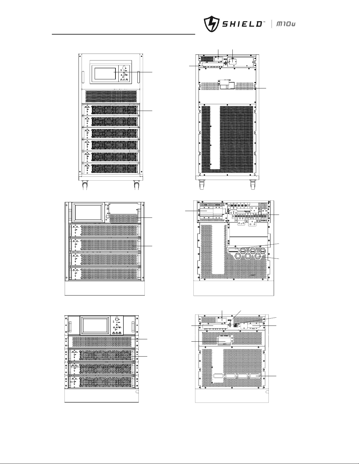
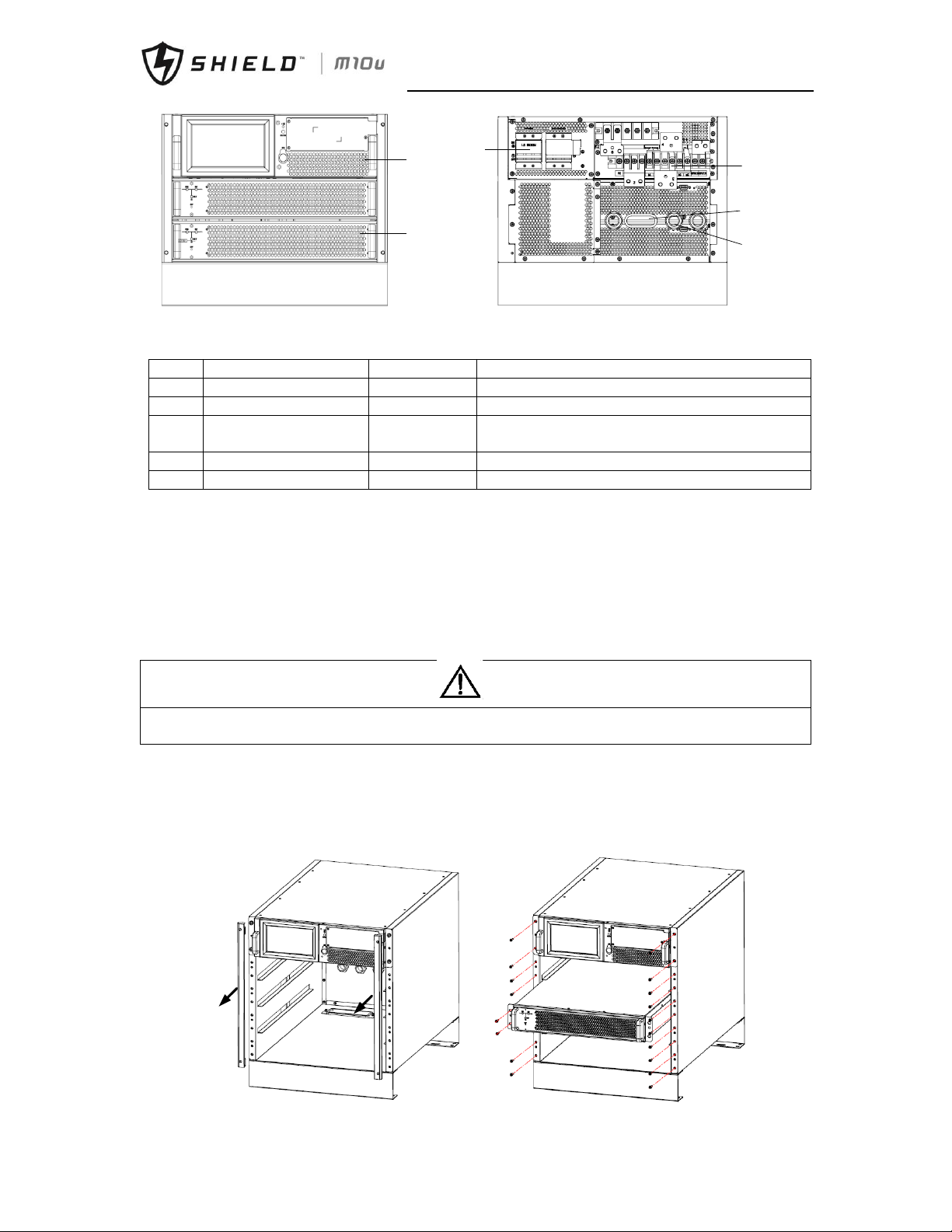
The UPS structure is shown in Fig. 1-1. The UPS configuration is provided in Table. 1-1
警告
危险
Page 13
Chapter 1 Installation
4 Shield M10U user manual
panel
Power
module
SNMP parallel
Dry
contactor
Manual
breaker
(a) 6 modules cabinet
Bypass
module
Power
module
connector
breakers
Ellipse
cable entry
Round
cable entry
(b) 4 modules cabinet
Bypass module
Power module
Manual bypass
Dry contactor
SNMP RS485
RS232
Parallel
Ellipse cable
entry
(c) 3 modules cabinet
Page 14
Chapter 1 Installation
Shield M10U user manual 5
Bypass
module
Power
module
breakers
connector
Ellipse
cable
entry
Round
cable
entry
(d) 2 modules cabinet
Fig.1- 1: UPS Structure
Table.1- 1: UPS Configuration List
Item
Component
Quantity
Remarks
1
System Display
1
Requisite, factory installed
2
Bypass module
1
Requisite, factory installed
3
Bypass/maintenance
bypass breakers
1
Requisite, factory installed
4
Power module
1 ≤n ≤6
Requisite
5
Decorative metal strip
2
Factory installed
1.4.8 Installing Power Modules
The number and possible installation positions of the Power Modules may vary according to the chosen factory
configuration. Please install the power modules from bottom to top, so as to avoid cabinet toppling due to high gravity
center.
Installation procedures of power modules
When installing power modules always work from the lower available space upwards to prevent from raising the center
of gravity. The default setting from the bottom space upwards is NO.1 to NO.2 (2 modules cabinet), NO.1 to NO.3 (3
modules cabinet), NO.1 to NO.4 (4 modules cabinet), NO.1 to NO.6 (6 modules cabinet).
Notes
If installed as standalone unit, it’s recommended that install power modules from upper available space downwards
to prevent from corrosion of the bottom module.
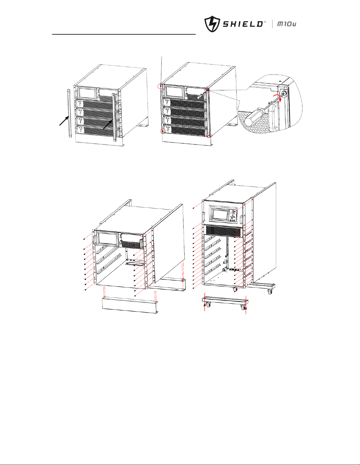
Recover decorative metal strips on the two side of front panel. Loose screws through holes on metal strips, pull
metal strips upwards then take away the strips as Fig.1-2(a).
Insert the module in the installation position, and push it into the cabinet.
Secure the module to the cabinet through the fixing holes on both sides of the front panel of the module.
Loose the upper and bottom 4 screws and fix two side decorative metal strips (as Fig.1-2) to cover the screws on
front side following Fig.1-2(c)(d).
警告
危险
Page 15
Chapter 1 Installation
6 Shield M10U user manual
(a) Remove side decorative metal strips (b) insert power module
Screws*4
(c) recover the decorative metal strips (d) fasten the strips
Fig.1- 2: Power Module Installation
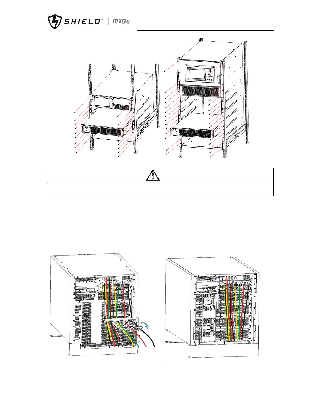
When using the UPS in a rack-mount configuration, the UPS must be supported by a slide kit, fixed rails or a shelf. Fasten
slide kit into the rack enclosure. Remove side panels and holders of UPS as Fig.1-3. Lay the UPS in rack-mounting position.
Fasten the UPS into the rack enclosure with (20)M6 screws
(a) Remove side panels and holders
Page 16
Chapter 1 Installation
Shield M10U user manual 7
b. fasten cabinet into rack enclosure
Fig.1- 3: rack mounted installation
Warning
Servicer rack enclosure within side doors should be chosen to cover side panel of UPS cabinet, otherwise the
connector for power modules might be touched with tools like screwdriver.
1.4.9 Cable Entry
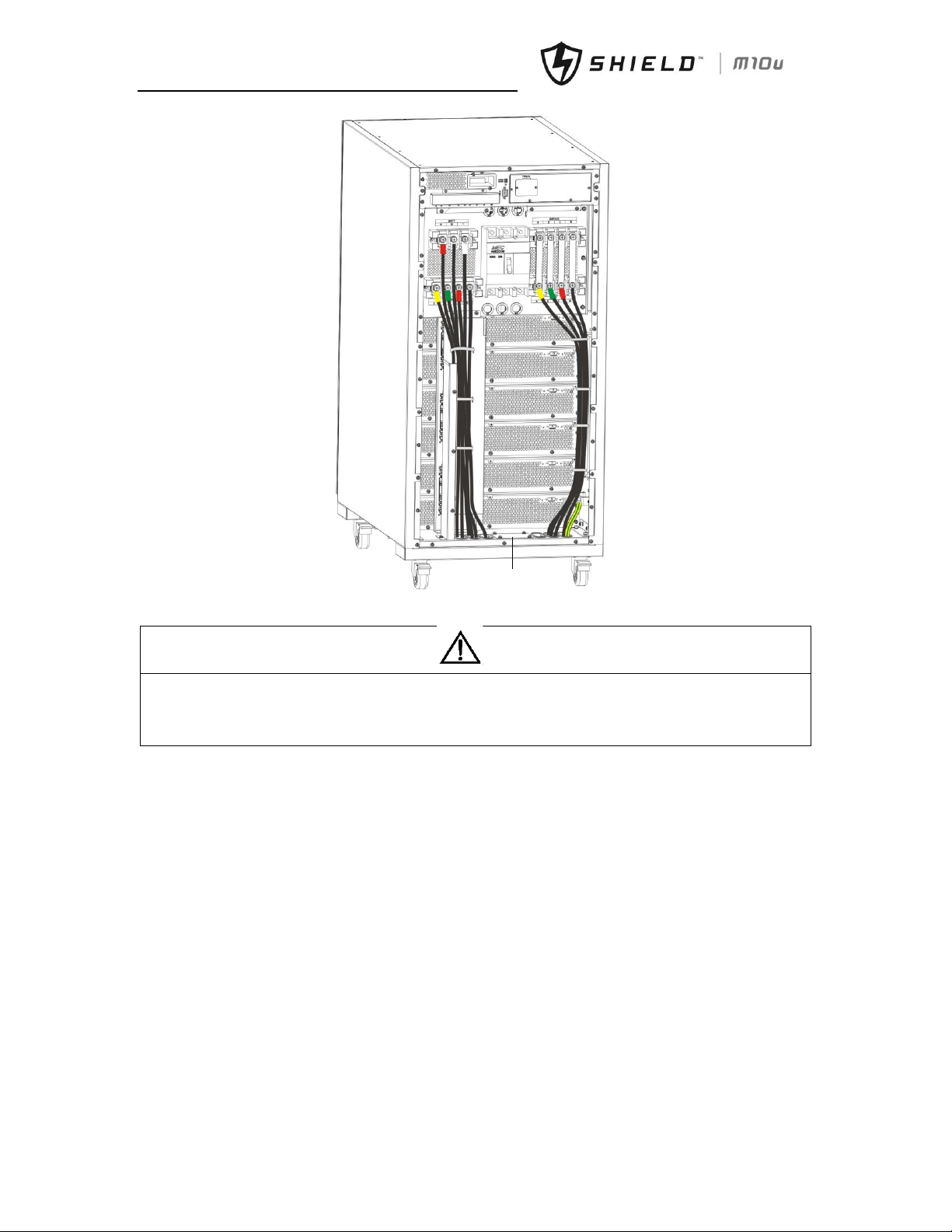
Cables can enter the module UPS rack system both from bottom and back. The recommended installation practice is to
connect cables through ellipse hole to prevent foreign material or vermin entering the cabinet. Use circular entry
protector if ellipse hole is not big enough. If connect cables through bottom entry, remove the cover and install a rubber
cable protector in the bottom entry hole firstly.
Cable entry is followed as fig.1-4.
(a) 2-module or 4-module cabinet cables entry
警告
危险
Page 17
Chapter 1 Installation
8 Shield M10U user manual
Reserved
entry hole
(b) 6-module cabinet cables entry
Fig.1- 4: cable entry
Notes
Cables connection should be followed as diagram on rear panel or appendix B (2-module and 4-module cabinet)
Fix cables in 6-module cabinet as Fig.1-4(b) to make sure best ventilation.
Enter through reserved entry cover if ellipse holes are not big enough, and block the remained space to protect UPS
from rats.
1.5 External Protective Devices
For safety concerns, it is necessary to install external circuit breakers or other protective devices for the input AC supply
of the UPS system. This section provides generic practical information for qualified installation engineers. The
installation engineers should have the knowledge of the regulatory wiring standards, and of the equipment to be
installed.
1.5.1 Rectifier and Bypass Input Supply of the UPS
Over currents
Install suitable protective devices in the distribution unit of the incoming mains supply, considering the power cable
current-carrying capacity and overload capacity of the system (see Tab. 9-7). Generally, the magnetic circuit breaker with
IEC60947-2 tripping curve C (normal) at the 125% of the current listed in Tab. 9-7 is recommended. Split bypass: In case
a split bypass is used, separate protective devices should be installed for the rectifier input and bypass input in the
incoming mains distribution panel.
Note: The rectifier input and bypass input must use the same neutral line.
Protection against earth faults (RCD devices):
The RCD device installed upstream of the input supply should:
警告
危险
Page 18
Chapter 1 Installation
Shield M10U user manual 9
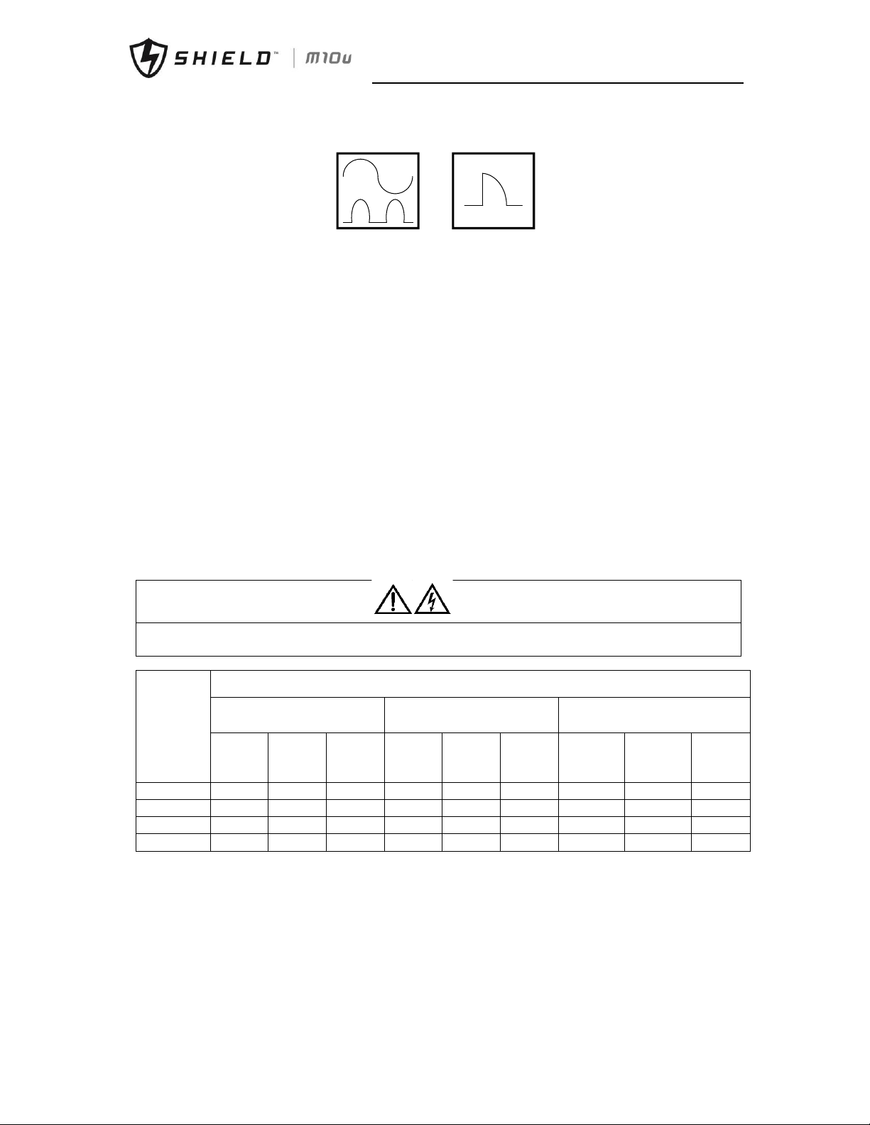
Sensitive to DC unidirectional pulses (class A) in the network
Insensitive to transient current pulses
Have an average sensitivity that is adjustable between 0.3A and 1A.
Fig.1- 5: The Symbols of RCCB
When using the RCD in the split bypass system or parallel system, the RCD should be installed in the upstream of the
input distribution to avoid wrong alarm.
The residual current introduced by RFI filter in the UPS is between 3.5mA and 1000mA. It is recommended to confirm the
sensitivity of each RCD of upstream input distribution and downstream distribution (to load).
1.5.2 External Battery
The DC compatible circuit breaker provides over current protection for UPS system and battery, which is provided by the
external battery cabinet.
1.5.3 UPS Output
In the eventuality that an external distribution panel is used for load distribution, the selection of protective devices
must provide discrimination with those that are used at the input to the UPS (see Tab. 9-7).
1.6 Power Cables
Design the cables according to the descriptions in this section and local regulatory wiring standards, and the
environmental conditions (temperature and physical support media) should be taken into consideration. Refer to
IEC60950-1 Table 3B Cabling.
WARNING
FAILURE TO FOLLOW ADEQUATE EARTHING PROCEDURES CAN RESULT IN EMI, ELECTRIC SHOCK HAZARD, OR RISK
OF FIRE, SHOULD AN EARTH FAULT OCCUR.
Table.1- 2: Maximum Steady State AC and DC Current
UPS
power(KVA
)
Rated current (A)
Main input current at full load
battery charging1,2
Output current at full load2
Battery discharging current at
E.O.D=1.67V/cell, no overload
380V
400V
415V
380V
400V
415V
36
Batt./stri
ng
38
Batt./stri
ng
40
Batt./st
ring
60
120
120
120
92
87
83
175
166
157
40
80
80
80
61
58
56
117
111
105
30
60
60
60
46
44
42
88
83
79
20
40
40
40
31
29
28
59
56
53
Note:
1. Input current of common input configurations of rectifier and bypass
2. Take special care when determining the size of the output and bypass neutral cable, as the current circulating on the neutral
cable may be greater than nominal current in the case of non-linear loads, which is usually 1.732 times of rated currents.
3. The earth cable connecting the UPS to the main ground system must follow the most direct route possible. The earth
conductor should be sized according to the fault rating, cable lengths, type of protection, etc.
According to AS/IEC60950-1, the cross section area of the conductor is 16mm2/10mm2 (40 input/output), the cross section
area of the conductor is 10mm2/6mm2 (10/20KVA input/output), the cross section area of the conductor is 35mm2/25mm2
(60kVA input/output).
4. When sizing battery cables, a maximum volt drop of 4Vdc. is permissible at the current ratings given in Table.1-2. The load
警告
危险
Page 19
Chapter 1 Installation
10 Shield M10U user manual
equipment is connected to a distribution network of individually protected busbars fed by the UPS output rather than
connected directly to the UPS. In parallel multi-module systems, the output cable of each ups rack unit should be kept at equal
length between the output of the ups rack output terminals and the parallel distribution busbars to avoid affecting the shared
current. When laying the power cables, do not form coils, so as to avoid the formation of electromagnetic interference.
5. See Chapter 4 Installation Drawing for the positions of wiring terminals.
WARNING
FAILURE TO FOLLOW ADEQUATE EARTHING PROCEDURES CAN RESULT IN EMI, ELECTRIC SHOCK HAZARD OR RISK
OF FIRE, SHOULD AN EARTH FAULT OCCUR.
1.6.1 Cable Connections
Note
The operations described in this section must be performed by authorized electricians or qualified technical
personnel. If you have any difficulties, do not hesitate to contactor our Customer Service & Support department.
After the equipment has been finally positioned and secured, refer to Chapter 4 Installation Drawing to connect the
power cables as described in the following procedures:
1. Verify that all the external input distribution switches of the UPS are completely opened and the UPS internal
maintenance bypass switch is opened. Attach necessary warning signs to these switches to prevent unauthorized
operation.
2. Open rear panel of the UPS, and then the power connection terminals are visible.
3. Connect the protective earth and any necessary grounding cables to the PE terminal. The cabinet for the UPS must be
connected to the user’s ground connection.
Note: The grounding cable and neutral cable must be connected in accordance with local and national codes practice.
Identify and make power connections for incoming cables according to one of the two procedures below, depending on the
type of installation:
Common Input Connections
4. For common bypass and rectifier inputs, connect the AC input supply cables to the UPS input terminals (input A-B-C-N)
Refer to Fig. 4-11 and tighten the connections to 5 Nm (M6 Bolt), 13Nm(M8 Bolt) or 25Nm (M10 Bolt). ENSURE CORRECT
PHASE ROTATION.
Split Bypass Connections(option)
5. If a 'split-bypass' configuration is used, connect the AC input supply cables to the rectifier input terminals (input A-BC-N) Refer to Fig.4-11 and the AC bypass supply cables to the bypass input terminals (bypass A-B-C-N) and tighten the
connections to 5 Nm (M6 Bolt) or 13Nm (M8 Bolt) or 25Nm (M10 Bolt). ENSURE CORRECT PHASE ROTATION.
Note: For split Bypass operation ensure that the busbars between Bypass and Rectifier inputs are removed. The neutral
line of bypass input must be connected to that of the rectifier input.
Frequency Converter Mode
If the frequency converter configuration is used, connect the AC input cables to the rectifier input terminals (input A-BC-N) Refer to Fig.4-11 and tighten the connections to 5Nm (M6 bolt), or to 13Nm (M8 bolt), or to 25Nm (M10 bolt).
ENSURE CORRECT PHASE ROTATION AND TIGHTEN CONNECTION TERMINALS. No need to connect the bypass input
cables to bypass input terminals (bA-bB-bC-bN).
Note: For the frequency converter operation mode, ensure that the busbars between Bypass and Rectifier inputs are
removed.
Output System Connections
6. Connect the system output cables between the UPS output busbars (output A-B-C-N) Refer to Fig.4-11 and the critical
load and tighten the connections to 5Nm (M6 Bolt) or to 13Nm (M8 Bolt) or to 25Nm(M10 Bolt). ENSURE CORRECT PHASE
ROTATION.
WARNING
If the load equipment will not be ready to accept power on the arrival of the commissioning engineer, then ensure
that the system output cables are safely isolated at their ends.
7. Re-install all the protective covers.
警告
危险
警告
危险
警告
危险
Page 20
Chapter 1 Installation
Shield M10U user manual 11
1.7 Control Cabling and Communication
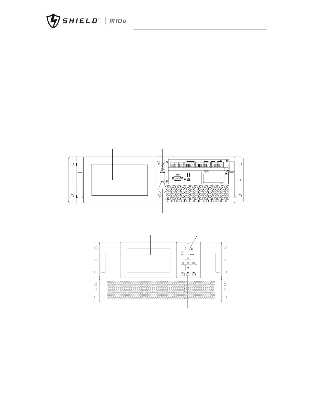
1.7.1 UPS Dry Contactor and Monitoring Board Features
According to the specific needs of the field, the UPS may need auxiliary connection to realize the management of the
battery system (including external battery switch and battery temperature sensor), communicate with PC, provide alarm
signal to external device, or realize remote EPO. These functions are realized through the UPS dry contactor board (GJ)
and monitoring board (JK) at the front of bypass module. The boards provide the following interfaces:
EPO
Environment and battery temperature input interface
Generator input dry contactor interface
Battery warning output dry contactor interface
Battery circuit breaker interface
Mains failure warning output dry contactor interface
Intellislots (TM) intelligent card interface
User communication interface
The UPS dry contactor board provides input dry contactors and output dry contactors.
LCD
Indicator LED
Dry
contactor
EPO
RS232
RS485
SNMP
(a) 20kVA/40kVA bypass module
Functional button
LCD LED indicator EPO
(b) 30kVA/45kVA bypass module
Page 21
Chapter 1 Installation
12 Shield M10U user manual
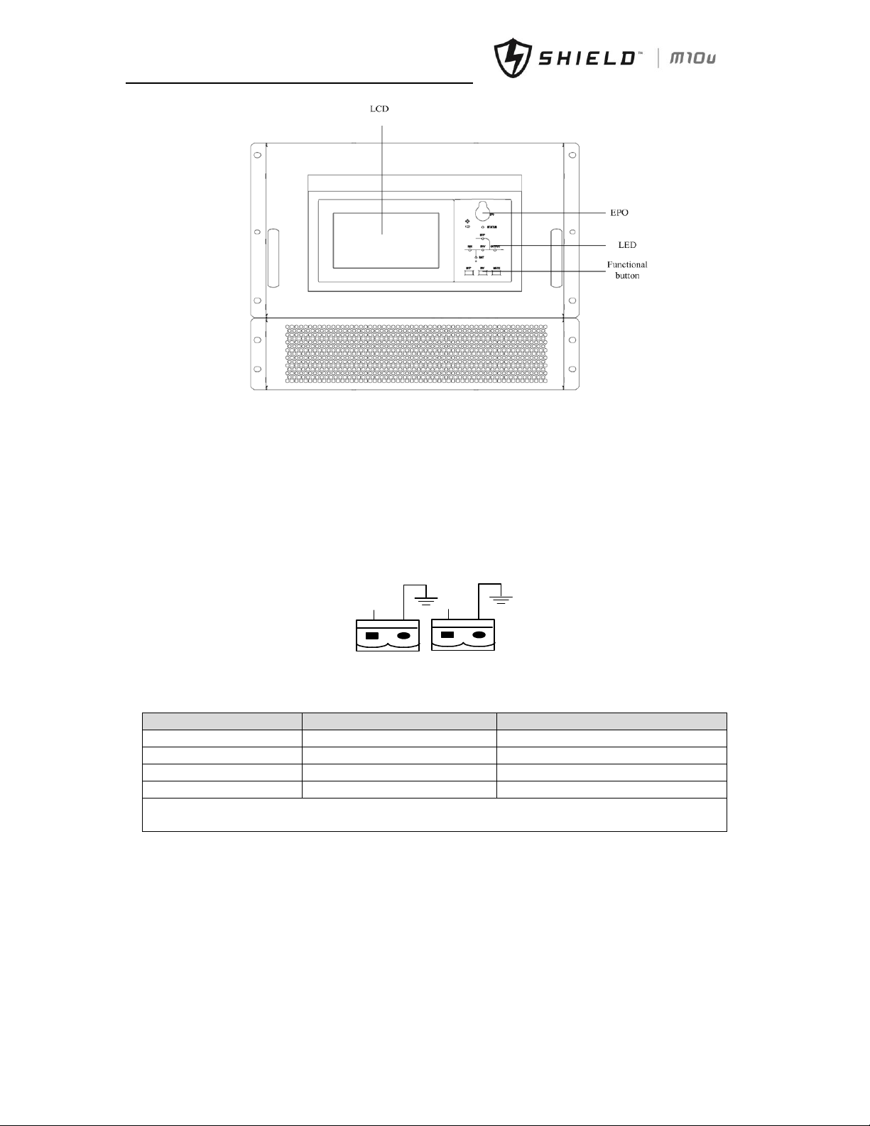
(c) 90kVA bypass module
Fig.1- 6: Bypass Module (include bypass and monitoring)
1.7.2 Dry Contactor Interface of Battery and Environmental Temperature Detection
The input dry contactor J2 and J3 detect the temperature of batteries and environment respectively, which can be used
in environment monitoring and battery temperature compensation.
J2 and J3 interfaces diagram are shown in fig.1-5, the description of interface is in table.1-3.
J2 J3
TEMP_BAT
TEMP_ENV
Fig.1- 7: Diagram of J2 and J3 Dry Contactor of Temperature Detection
Table.1- 3: Description of Input Dry Contactor
Position
Name
Purpose
J2.1
TEMP_BAT
Battery temperature detection
J2.2
TEMP_COM
Common terminal
J3.1
TEMP_ENV
Environment temperature detection
J3.2
TEMP_COM
Common terminal
Note: Specified temperature sensor is required for temperature detection (R25=5Ohm, B25/50=3275), please
confirm with the manufacturer, or contactor local maintenance engineers when placing an order.
1.7.3 Remote EPO Input Port
The UPS has an Emergency Power OFF (EPO) function. This function can be activated by pressing a button on the control
panel of the UPS or through a remote contactor provided by the user. The EPO pushbutton is protected by a hinged
plastic cover.
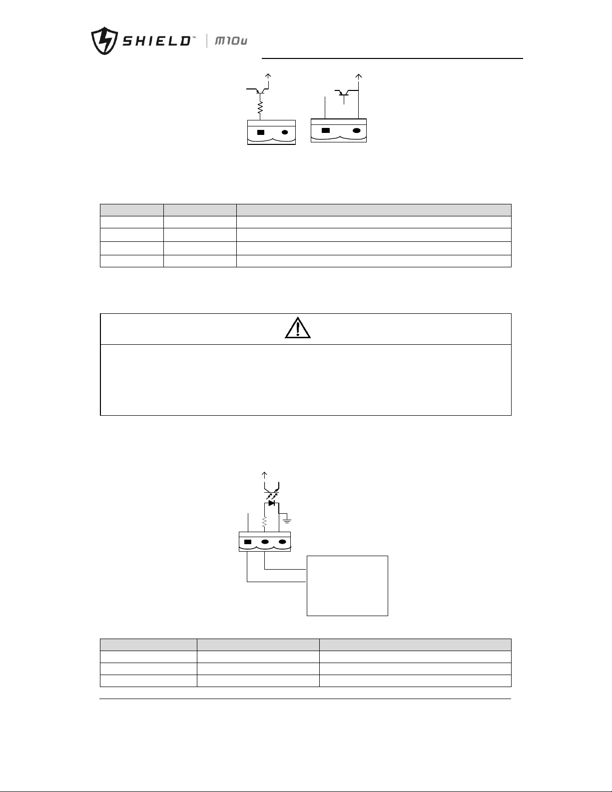
J4 is the input port for remote EPO. It requires shorting NC and +24v during normal operation, and the EPO is triggered
when opening NC and +24v, or shorting NO and +24v. The port diagram is shown in fig.1-6, and port description is shown
in table.1-4.
Page 22
Chapter 1 Installation
Shield M10U user manual 13
+24V
+24V
J4
EPO_NO
+24V
+24V
+24V
Fig.1- 8: Diagram of Input Dry Contactor for Remote EPO
Table.1- 4: Description of Input Dry Contactor for Remote EPO
Position
Name
Purpose
J4.1
EPO_NC
EPO is activated when disconnecting fromJ4.2
J4.2
+24V
+24V, connect the common terminal of NC
J4.3
+24V
+24V, connect the common terminal of NO
J4.4
EPO_NO
EPO is activated when shorting with J4.3
The EPO is triggered when shorting pin 3 and 4 or opening pin 1 and 2 of J4.
If an external emergency stop facility is required, it is connected via the reserved terminals of J4. The external emergency
stop facility needs to use shielded cables to connect to the normally open/closed remote stop switch between these two
pins. If this facility is not used, then pin 3 and pin 4 of J4 must be open, or pin 1 and pin 2 of J4 must be shorted.
Note
1. The emergency stop action within the UPS will shut down the rectifier, inverter and static bypass. However, it
does not internally disconnect the mains input power supply. To disconnect ALL power to the UPS, open the
upstream input circuit breaker(s) when the EPO is activated.
2. Pin 1 and 2 of J4 have been shorted before the UPS is delivered.
3. All auxiliary cables must be double insulated twisted cables with cross sectional area of 0.5mm2 ~ 1.5mm2 for
maximum connection length between 25m and 50m.
1.7.4 Generator Input Dry Contactor
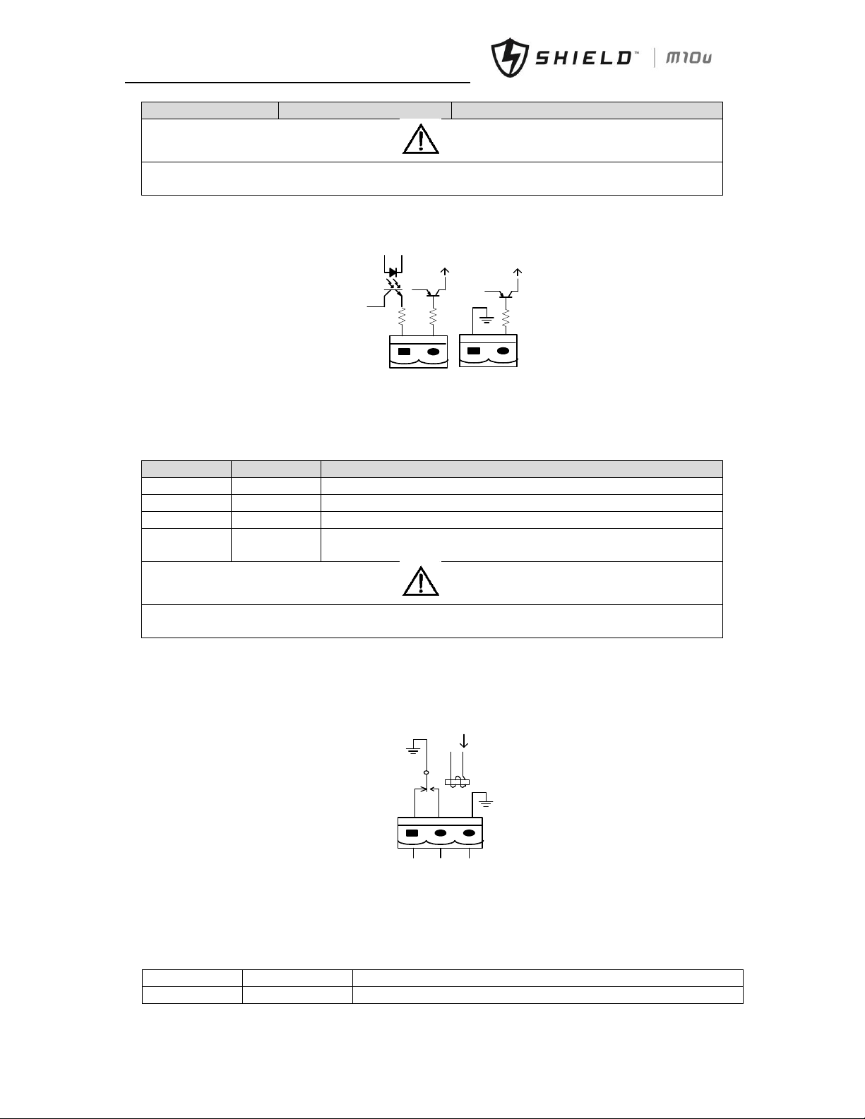
J5 is the status interface for generator connection. Connect J5-2 with J5-1, it indicates that the generator has been
connected with the system. The interface diagram is shown in fig.1-7, and interface description is shown in table.1-5.
J5
+24V
AUX_N.O.
AUX_N.O.
Gernerator
Fig.1- 9: Connection of Generator
Table.1- 5: Description of Status Interface and Connection of Generator
Position
Name
Purpose
J5.1
+24V
Internal +24V power supply
J5.2
GEN
Connection status of generator
J5.3
GND
Power ground
警告
危险
Page 23
Chapter 1 Installation
14 Shield M10U user manual
Position
Name
Purpose
Note
All auxiliary cables must be double insulated twisted cables with cross sectional area of 0.5mm2 ~ 1.5mm2 for
maximum connection length between 25m and 50m.
1.7.5 BCB Input Port
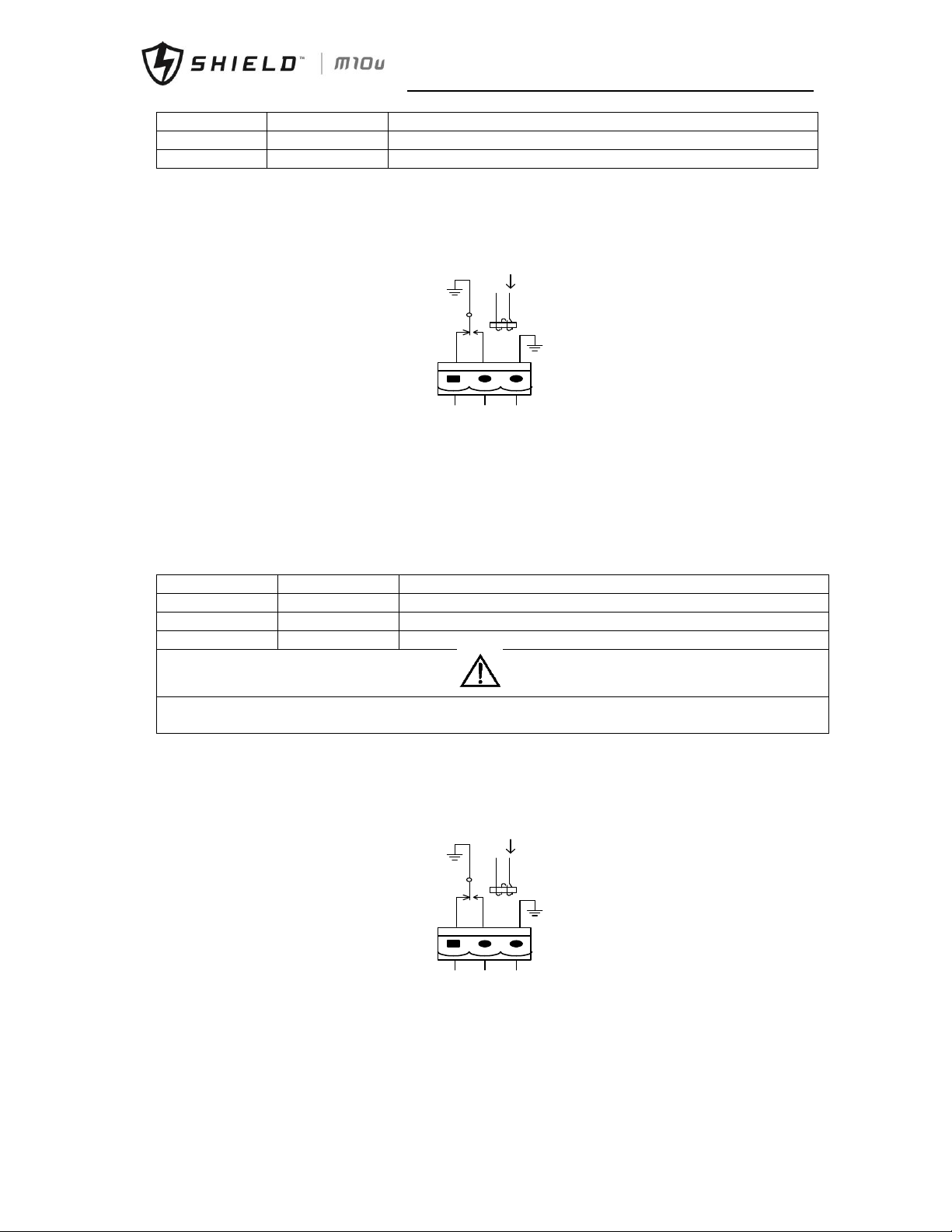
J6 and J7 are the ports of BCB. The diagram is shown in fig.1-8, and description is shown in table.1-6.
BCB_DRV
BCB_CONT
J6
J7
BCB_ONL
+24V
+24V
+24V
Fig.1- 10: BCB Interface
Table.1- 6: Description of BCB Interface
Position
Name
Description
J6.1
BCB_DRV
BCB actuating signal, provide the actuating signal of +24V, 20mA
J6.2
BCB_CONT
BCB contactor status, connect with the normally open signal of BCB
J7.1
GND
Common connection
J7.2
BCB_ONL
BCB on-line–input (normally open) , BCB is on-line when the signal is
connecting with common connection
Note
All auxiliary cables must be double insulated twisted cables with cross sectional area of 0.5mm2 ~ 1.5mm2 for
maximum connection length between 25m and 50m.
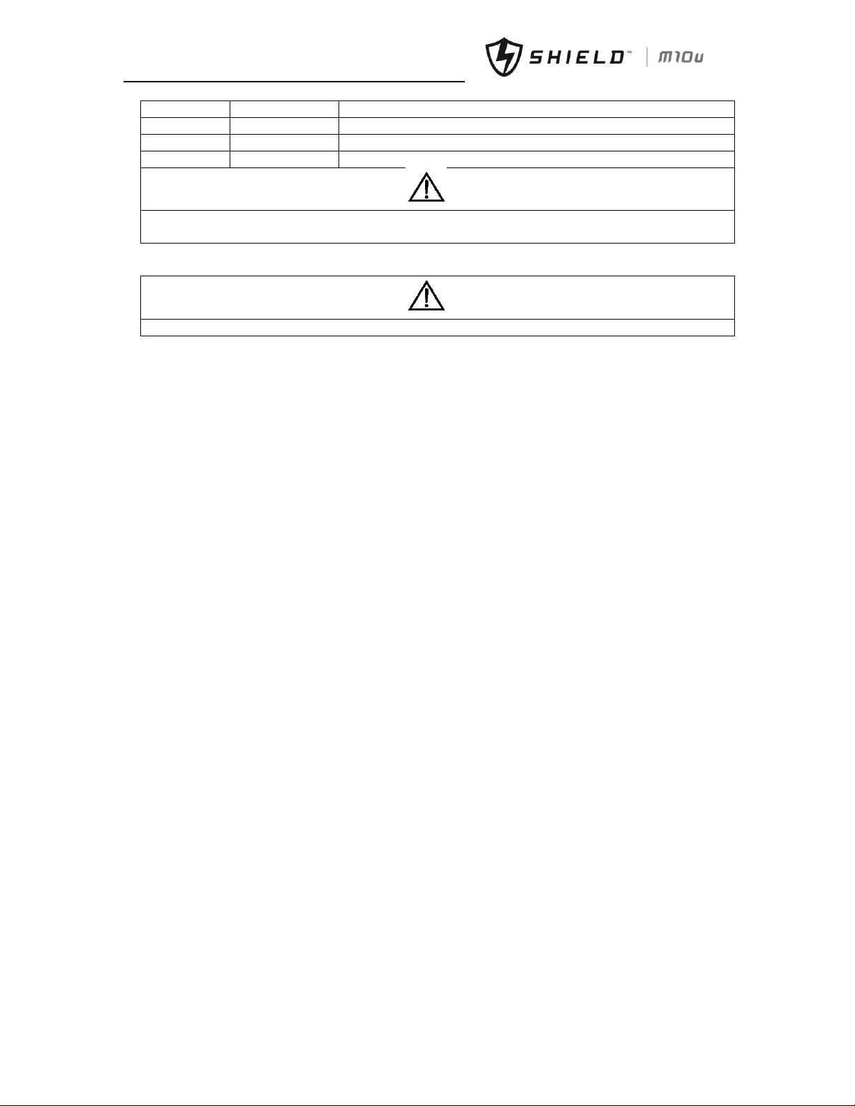
1.7.6 Battery Warning Output Dry Contactor Interface
J8 is the output dry contactor interface, which outputs the battery warnings of low or excessive voltage, when the
battery voltage is lower than set value, an auxiliary dry contactor signal will be provided via the isolation of a relay. The
interface diagram is shown in fig.1-9, and description is shown in table.1-7.
J8
BAT_LOW_NC
BAT_LOW_NO
GND
Fig.1- 11: Battery Low Warning Dry Contactor
Table.1- 7: Battery warning dry contactor interface description
Position
Name
description
J8.1
BAT_LOW_NC
Battery warning relay (normally closed) will be open during warning
警告
危险
警告
危险
Page 24
Chapter 1 Installation
Shield M10U user manual 15
Position
Name
description
J8.2
BAT_LOW_NO
Battery warning relay (normally open) will be closed during warning
J8.3
GND
Commom connection
1.7.7 Integrated Warning Output Dry Contactor Interface
J9 is the integrated warning output dry contactor interface, when one or more than one present warning is triggered,
the system will send an integrated warning information, and provide an auxiliary dry contactor signal via the isolation of
a relay. The interface diagram is shown in fig.1-10, and description is shown in table.1-8.
J9
ALARM_NC
ALARM_NO
GND
Fig.1- 12: Integrated warning dry contactor
Table.1- 8: Integrated warning dry contactor interface description
Position
Name
Purpose
J9.1
ALARM_NC
Integrated warning relay (normally closed) will be open during warning
J9.2
ALARM_NO
Integrated warning relay (normally open) will be closed during warning
J9.3
GND
Common connection
Note
All auxiliary cables must be double insulated twisted cables with cross sectional area of 0.5mm2 ~ 1.5mm2 for maximum
connection length between 25m and 50m.
1.7.8 Mains Failure Warning Output Dry Contactor Interface
J10 is the output dry contactor interface for utility failure warning, when the utility fails, the system will send a utility
failure warning information, and provide an auxiliary dry contactor signal via the isolation of a relay. The interface
diagram is shown in fig.1-11, and description is shown in table.1-9.
J10
UTI_FAIL_NC
UTI_FAIL_NO
GND
Fig.1- 13: Utility Failure Warning Dry Contactor
Table.1- 9: Description of Mains failure warning dry contactor
警告
危险
Page 25
Chapter 1 Installation
16 Shield M10U user manual
Position
Name
Purpose
J10.1
UTI_FAIL_NC
Mains failure warning relay(normally closed) will be open during warning
J10.2
UTI_FAIL_NO
Mains failure warning relay (normally open) will be closed during warning
J10.3
GND
Common connection
Note
All auxiliary cables must be double insulated twisted cables with cross sectional area of 0.5mm2 ~ 1.5mm2 for
maximum connection length between 25m and 50m.
Note
Connect dry contactoror cables as Fig.4-12
警告
危险
警告
危险
Page 26
Chapter 2 Battery Installation
Shield M10U user manual 17
Chapter 2 Battery Installation and Maintenance
2.1 General Recommendations
Take special care when operating the batteries of the Modular UPS system. When all the battery cells are
connected, the battery voltage can exceed 400Vdc, which is potentially lethal.
Note
The precautions for battery installation, use and maintenance are to be provided by the batteries manufacturers.
The precautions in this section include the key issues that must be considered during the installation design, which
may be adjusted according to the specific local situations. Battery Room Design
The battery shall be installed and stored in a clean, cool and dry environment.
Do not install the battery in a sealed battery chamber or sealed room. The battery room ventilation shall at
least meet the requirement of EN50272-2001. Otherwise, battery bulging, fire and even human injury may be
caused.
The battery shall be installed far away from the heating source (e.g. transformer). Do not use or store the
battery in the place near the heating source or burn the battery or place it into fire. Otherwise, battery
leakage, bulging, fire or explosion may be caused.
Batteries shall be placed in such a manner that two bare live parts with the potential difference of more than
150V shall not be contactored at the same time. If it is unavoidable, insulated terminal cover and insulated
cables shall be used for connection.
If external batteries are to be used, the battery circuit breakers (or fuses) must be mounted as close as possible
to the batteries, and the connecting cables should be as short as possible.
Battery Handling
When connecting the battery, follow the precautions for high-voltage operation
Before accepting and using the battery, check the appearance the battery. If the package is damaged, or the
battery terminal is dirty, corroded or rusted or the shell is broken, deformed or has leakage, replace it with
new product. Otherwise, battery capacity reduction, electric leakage or fire may be caused.
Before operating the battery, remove the finger ring, watch, necklace, bracelet and any other metal
jewelry
Wear rubber gloves.
Eye protection should be worn to prevent injury from accidental electrical arcs.
Only use tools (e.g. wrench) with insulated handles.
The batteries are very heavy. Please handle and lift the battery with proper method to prevent any human
injury or damage to the battery terminal.
Do not decompose, modify or damage the battery. Otherwise, battery short circuit, leakage or even human
injury may be caused.
The battery contains sulfuric acid. In normal operation, all the sulfuric acid is attached to the separation board
and plate in the battery. However, when the battery case is broken, the acid will leak from the battery.
Therefore, be sure to wear a pair of protective glasses, rubber gloves and skirt when operating the battery.
Otherwise, you may become blind if acid enters your eyes and your skin may be damaged by the acid.
At the end of battery life, the battery may have internal short circuit, drain of electrolytic and erosion of
positive/negative plates. If this condition continues, the battery may have temperature out of control, swell or
leak. Be sure to replace the battery before these phenomena happen.
If a battery leaks electrolyte, or is otherwise physically damaged, it must be replaced, stored in a container
警告
危险
警告
危险
警告
危险
Page 27
Chapter 2 Battery Installation
18 Shield M10U user manual
resistant to sulfuric acid and disposed of in accordance with local regulations.
If electrolyte comes into contactor with the skin, the affected area should be washed immediately with water.
2.2 Battery Typologies
According to the requested configuration UPS may need batteries consisting of one or more strings of battery blocks
installed on shelves in a locked cabinet or dedicated battery room
Note
The Traditional external battery cabinet can make use of each even number of battery per string between 36 and
44.
The default factory setting, if the unit is ordered w/o internal battery is 40.
The cabinet is only for valve regulated maintenance-free lead-acid battery.
CAUTION: The lead acid battery may cause chemistry hazard
2.2.1 Traditional Battery Installation
Only the qualified engineers are allowed to install and maintain mounted in a traditional battery cabinet or shelf. To
ensure safety, install the external battery in a locked cabinet or dedicated battery room accessible just to service
qualified personnel.
Please note that number of cells set via software must be consistent with the actual number of cells.
A minimum space of 10mm must be reserved on all vertical sides of the battery block to permit free air movement around
the cells.
A certain clearance should be reserved between the top of the cells and the underside of the shelf above as this is
necessary for monitoring and servicing the cells.
When installing the batteries always work from the bottom shelf upwards to prevent raising the center of gravity.
Install the batteries reliably and avoid vibration and mechanical bumping.
The bending radius of cable should be more than 10D, where "D" is the outer diameter of cable.
When connecting the cable, do not cross the battery cables and do not bind the battery cables together. The battery
connection must be firm and reliable. After the connection, all the connections between the wiring terminals and the
batteries must be corrected to meet the torque requirement provided in the specifications and user manuals of the
battery manufacturers.
Each battery terminal should be insulated after its connection has been made.
Check if the battery is unexpectedly grounded. If the battery is unexpectedly grounded, remove the earth power supply.
Contactoring any part of the grounded earth may be subject to electric shock.
Measure the battery voltage and carry out battery voltage calibration after the UPS is started.
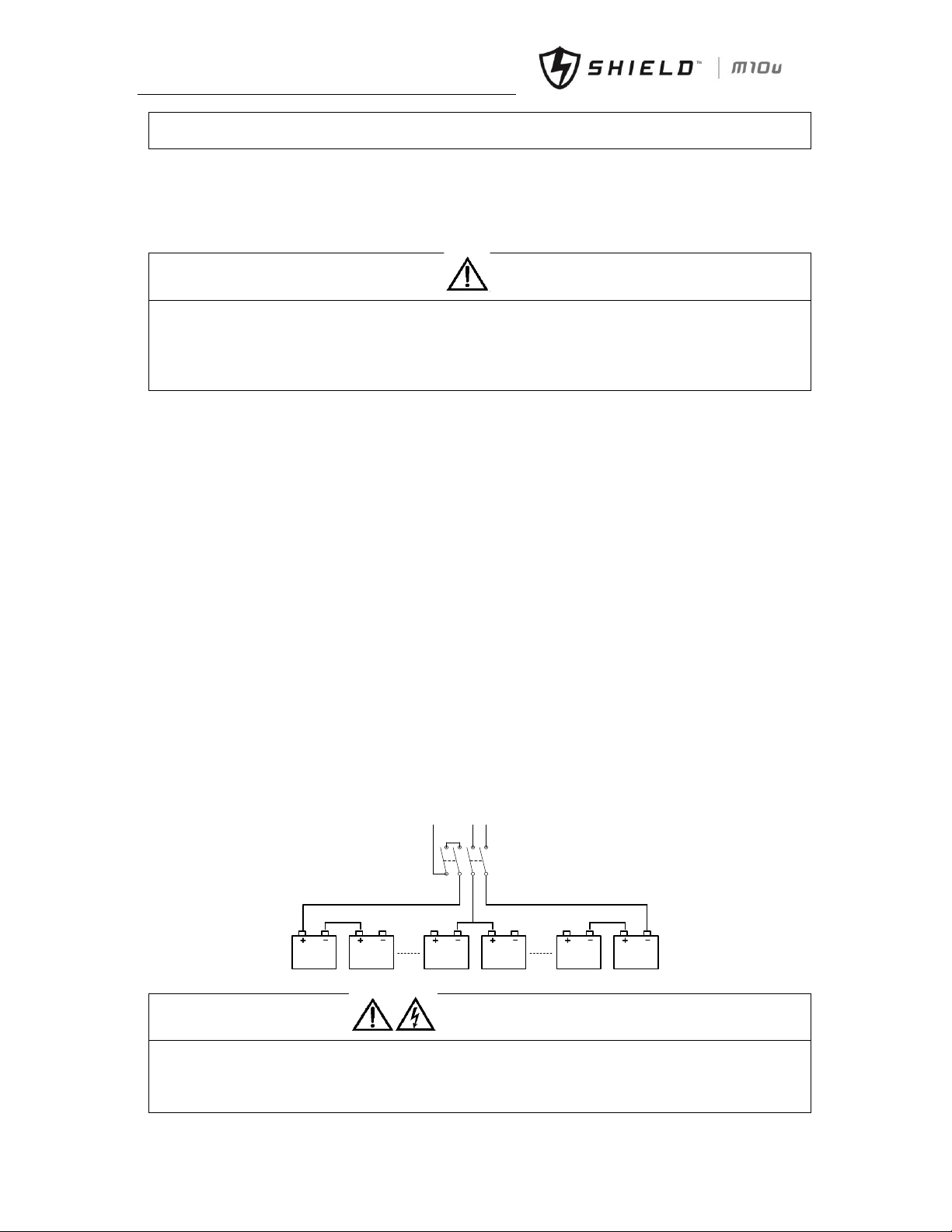
Diagram of batteries connection is shown as below:
1 2 20 21 39 40
Bat+
N Bat-
Fig.2- 1: Diagram of Batteries Connection
Warning: Battery connections
When using a traditional battery solution, always comply with the following precautions:
Disconnect the charging power before connecting or disconnecting the cable of the battery terminals.
Do not connect the cables between the UPS battery terminals and the batteries before getting the approval
from the commissioning engineer.
警告
危险
警告
危险
Page 28

Chapter 2 Battery Installation
Shield M10U user manual 19
When connecting the cables between the battery terminals and the circuit breaker, always connect the circuit
breaker end of the cable first.
Be sure to connect the positive/negative terminals of the batteries to those of the circuit breakers and those
of the circuit breakers to those of the UPS respectively with reference to the markings of positive/negative
terminals. Reverse connection of battery polarities will result in explosion, fire accident, the damage of
batteries and UPS, and human injury.
The battery connecting terminal shall not subject to any external force, such as the pulling force or twisting
force of the cable. Otherwise, the internal connection of the battery may be damaged, and in severe case, the
battery may catch fire.
Do not connect power until the total voltage of the battery string is verified correct through measurement.
Do not connect any conductor between the positive and negative terminals of the battery.
Do not close the battery circuit breakers before getting the approval from the commissioning engineer.
2.3 Battery Maintenance
For the battery maintenance and precautions, please refer to IEEE-Std-1188-2005 and the relevant manuals provided by
the battery manufacturers.
Battery Maintenance Note
Check to ensure that all the safety devices are in place and function normally. Check if the battery
management parameter setting is normal particularly.
Measure and record the air temperature in the battery room.
Check if the battery terminals are damaged or have the symptom of heating, and if the shell or cover is
damaged.
Please fasten every bolt on the terminal according to the fastening torque specified in the table below.
After 1-2 months of service, recheck to make sure that each screw has been fastened according to the specified
torque. Otherwise there is risk of fire.
CAUTION: Use the battery with the same capacity and type, if battery is replaced by an incorrect type, it can
cause explosion.
CAUTION: Dispose of used battery according to the local instructions
警告
危险
Page 29
Chapter 3 Installation of UPS Rack System and System
20 Shield M10U user manual
Chapter 3 Installation of UPS Rack System
3.1 Overview
The single system should be installed according to the installation procedures of the UPS rack module system and the
requirements in this Chapter.
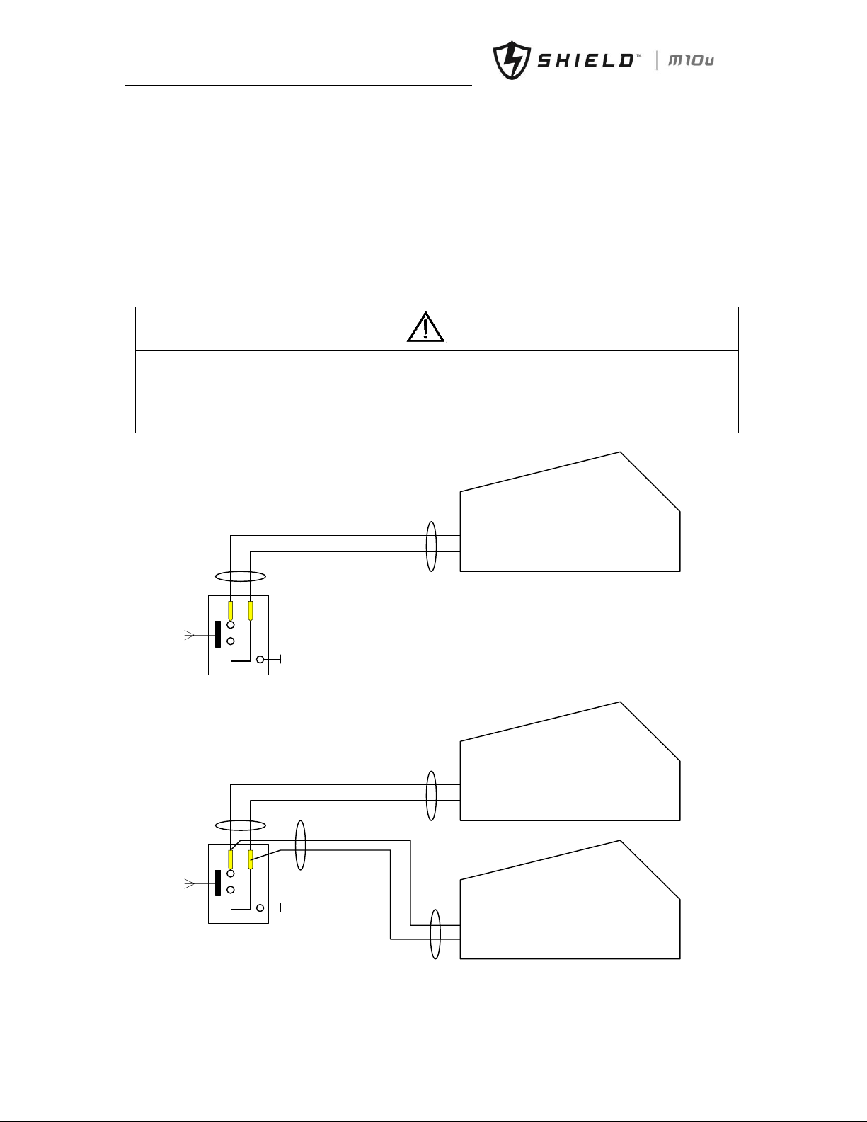
For single UPS rack module installation the EPO button on the front panel of the UPS rack controls the emergency stop
of UPS modules and bypass static switch and also supports remote emergency power off function that can be used to
shut down the UPS rack module remotely.
Note
1. The remote EPO switch must provide normally open or normally closed dry contactor signals.
2. The open circuit voltage is 24Vdc, and the current is less than 20mA.
3. Normally closed EPO-J4 terminals: Pin 1 and pin 2 have been connected in factory and located on the dry contactor
board.
4. Set EPO function as available with monitoring software on PC before using remote EPO function.
UPS1
Dry contact board
J4-3
J4-4
(a) Single unit
UPS1
Dry contact board
J4-3
J4-4
UPS2
Dry contact board
J4-3
J4-4
(b) Parallel system
Fig.3- 1: Circuit diagram of EPO
警告
危险
Page 30
Chapter 3 Installation of UPS Rack System and Parallel Syste
m
Shield M10U user manual 21
3.2 UPS Rack Modules in Parallel System
The basic installation procedures of parallel system are the same with those of the UPS rack module system. In this
section, only the installation procedures related to the parallel system are introduced.
3.2.1 Installation of Cabinet
To make the maintenance and system test easier, an external maintenance bypass is recommended in the installation.
3.2.2 External Protective Devices
Refer to Chapter 1 Installation
3.2.3 Power Cables
The power cable connection of the parallel rack module system is similar to that of the single UPS rack module system.
If the bypass input and rectifier input share the same neutral terminal and if an RCD protective device is installed at the
input, then the RCD device must be installed before the input cables are connected to the neutral terminal. Refer to
Chapter 1 Installation
Note: The length and specification of the power cables of each UPS module should be the same, including the bypass
input cables and UPS output cables, so that the load sharing effect can be achieved in bypass mode.
3.2.4 Parallel Signal Board
Installation of parallel signal board
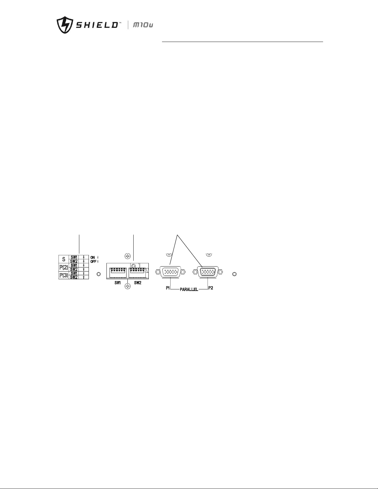
The parallel signal board is installed at the rear of the cabinet. Shown as below:
CAN bus set Communication ports
CAN bus
setting indicator
Fig.3- 2: Parallel Board
3-slots cabinet and 6-slots cabinet:
The switches SW1 and SW2 on the UPS should be set as below:
Single- all switches ON
2 paralleled- switch SW1 ON, switch SW2 OFF
3 paralleled- all switches OFF
2-slots cabinet and 4-slots cabinet:
No need to modify CAN bus setting.
3.2.5 Control Cables
Parallel control cable
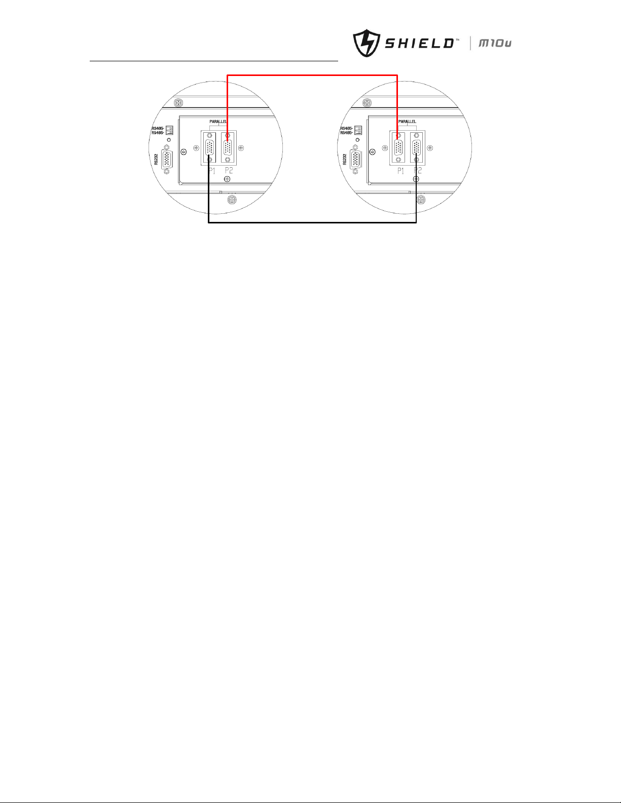
The parallel control cables are designed to be shielded and double insulated, DB15 terminals, and are connected between
the UPS rack modules to form a loop as shown below. The parallel signal board is installed at the rear of the cabinet. This
close loop connection ensures the reliability of the parallel system control. Refer to fig. 3-3
Page 31
Chapter 3 Installation of UPS Rack System and System
22 Shield M10U user manual
UPS1
UPS2
Fig.3- 3: Connection of Parallel Cables of "1+N" System
Page 32
Chapter 4 Installation Drawing
Shield M10U user manual 23
Chapter 4 Installation Drawing
Rack Modular
UPS system
To User Safety
Ground
Input
Output
Connect to
Critical Load
Main Supply
Bypass
Bypass
Supply
Power Cables
External Batt.
+ N -
To External Battery
Connection
Dry Contact Board
SNMP
SNMP Card
RS232
RS485
J2
J3
J4
J5
J6
J7
J8
J9
J10
Batt.
Temperature
ENV.
Temperature
EPO
GEN
BCB
Batt. Low
Alarm
General
Alarm
Utility
Fail
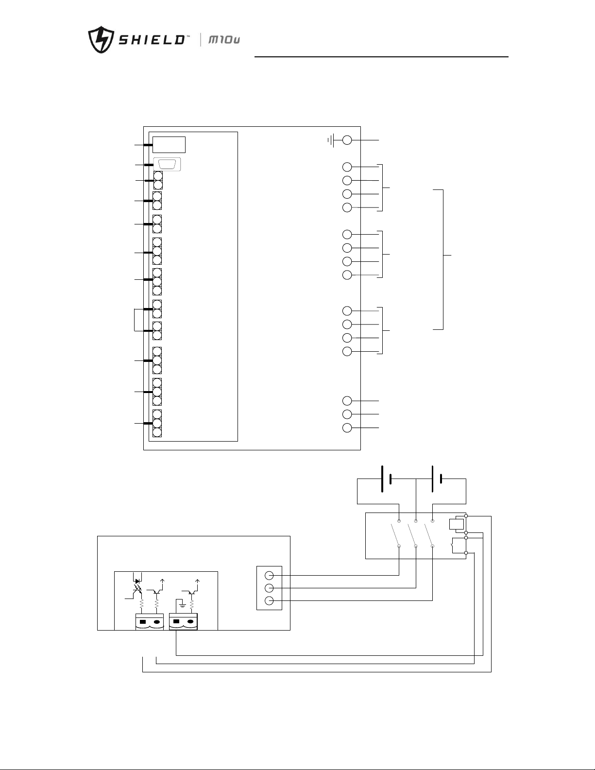
Fig.4- 1: Wiring Diagram
BCB
UV
Batt. +
Batt. N
Batt. -
Rack Modular UPS
BCB_DRV
BCB_CONT
J6
J7
BCB_ONL
+24V
+24V
+24V
24VDC
Auxiliary
Contactor
BCB DRV
BCB STATUS
GND
Fig.4- 2: External Battery Connection
Page 33
Chapter 4 Installation Drawing
24 Shield M10U user manual
External BCB interface:
BCB DRV: J6-1 BCB drive signal
BCB STATUS: J6-2 BCB contactoror status, normally opened. Shorted to GND when activated
GND: J7-1 ground
panel
Power
module
Side
decorative
strip*2
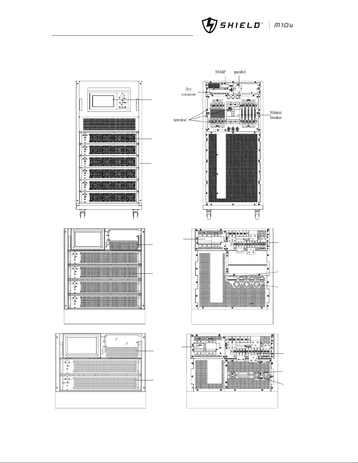
Fig.4- 3: 6 modules UPS System, Front View and Rear View without Door
Bypass
module
Power
module
connector
breakers
Ellipse
cable entry
circular
cable entry
Fig.4- 4: 4 Modules UPS System, Front View and Rear View without Door
Bypass
module
Power
module
breakers
connector
Ellipse
cable
entry
circula
r cable
entry
Fig.4- 5: 2 Modules UPS System, Front View and Rear View without Door
Page 34
Chapter 4 Installation Drawing
Shield M10U user manual 25
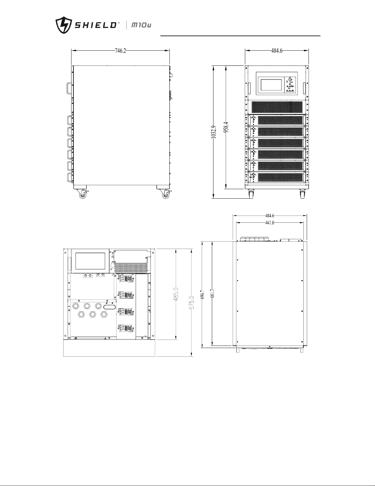
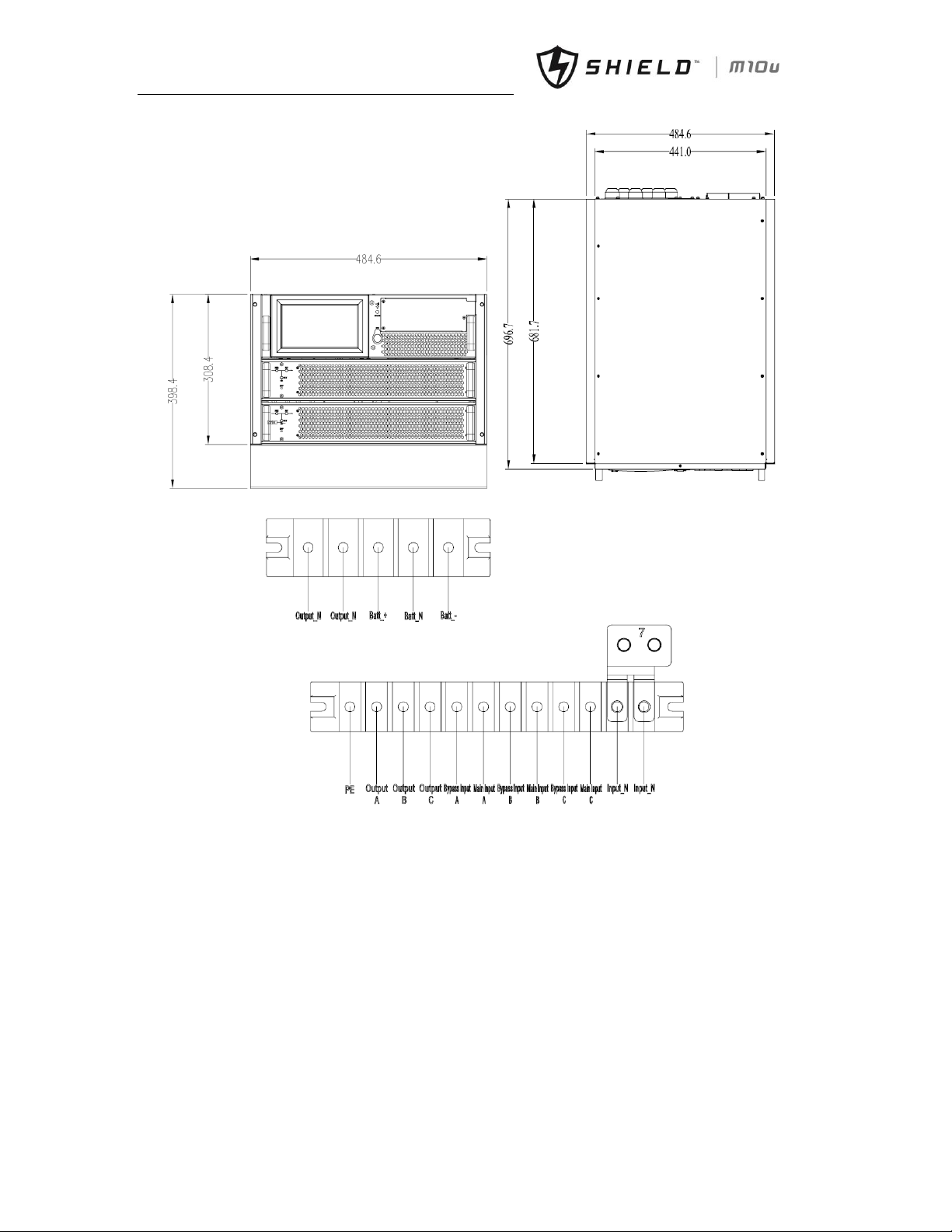
Fig.4- 6: 6 Modules UPS External Dimensions
Fig.4- 7: 4 Modules UPS External Dimensions
Page 35
Chapter 4 Installation Drawing
26 Shield M10U user manual
Fig.4- 8: 2 Modules UPS External Dimensions
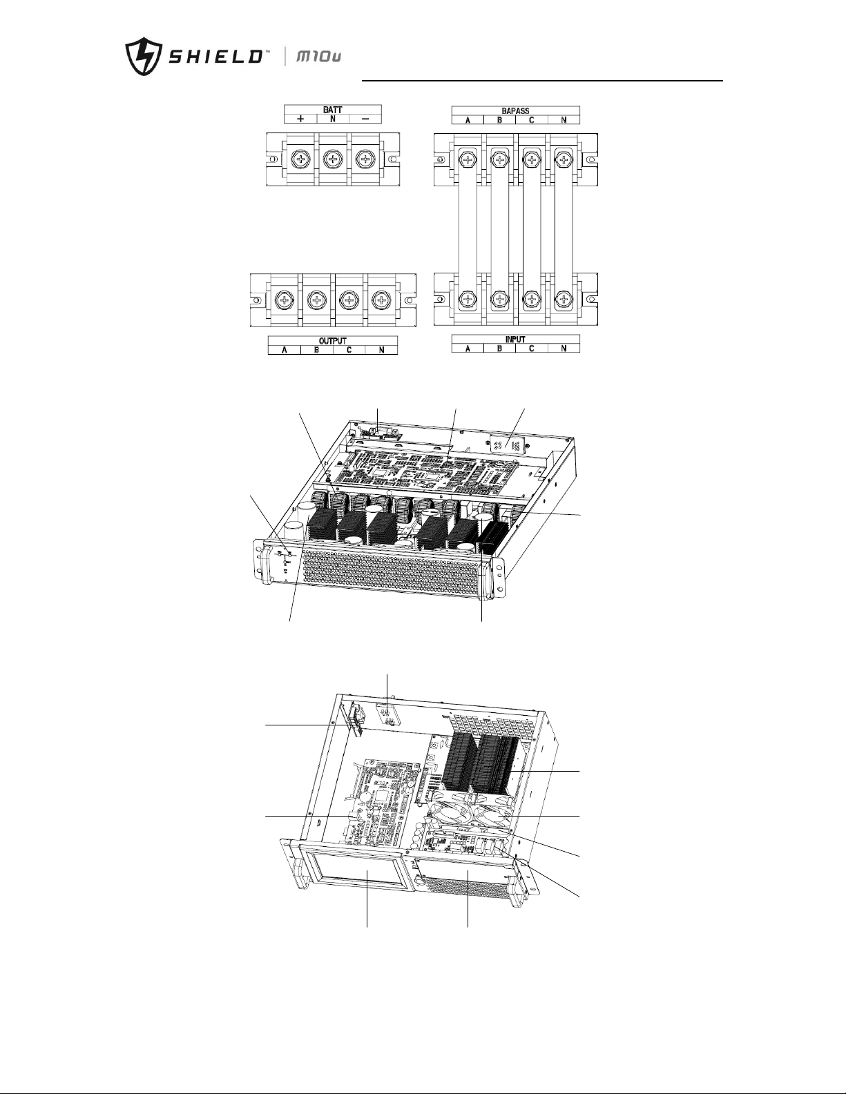
(a) 20KVA/40KVA power connection
Page 36
Chapter 4 Installation Drawing
Shield M10U user manual 27
(b) 60KVA power connection
Fig.4- 9: Power Connection of Module System UPS
Input power board DSP burn-in board DSP board
Output power
board
PFC power
board
INV power board
Fan control
board
connector
Fig.4- 10: Power Module
connector
Bypass
power
board
Bypass fans
Power
supply
Dry
contactor
Burn-in
board
Monitoring
board
LCD
Cover
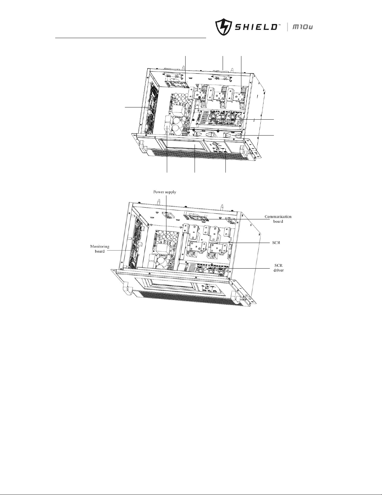
(a) 20KVA/40KVA Bypass Module
Page 37
Chapter 4 Installation Drawing
28 Shield M10U user manual
Communication borad connector
Bypass
SCR
Monitoring
board
Power supply board
LCD
keyboard
fans
Driver
board
(b) 30kVAKVA bypass module
(c) 60KVAKVA Bypass Module
Fig.4- 11: Monitoring and Bypass Module
Notes for installing modules:
1. When installing the modules, install the modules from bottom to top. When removing the modules, remove the
modules from top to bottom. The purpose is to maintain the stable center of gravity.
2. After inserting the module, tighten all the screws.
3. When removing the modules, turn off modules first, remove the screws and then remove the modules.
4. Wait for 5 minutes before inserting the removed modules.
Page 38
Chapter 4 Installation Drawing
Shield M10U user manual 29
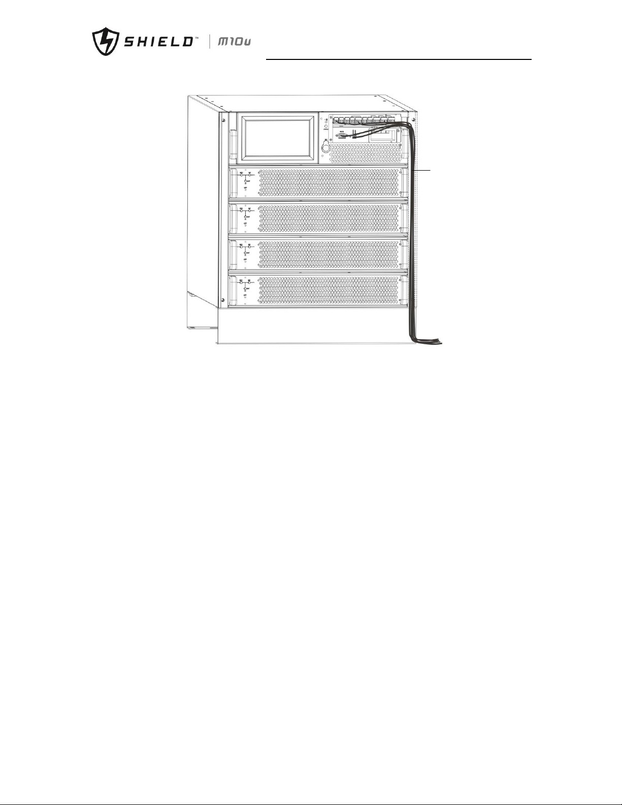
Cables
routing in
decorative
metal strip
Fig.4- 12: cables routing (dry contactoror, RS485, SNMP)
Notes for signal cables routing:
1. Remove cover on front panel and remove right metal strip
2. Connect cables and route as Fig.4-12
3. Cover right metal strip back to UPS to cover the cables
Page 39
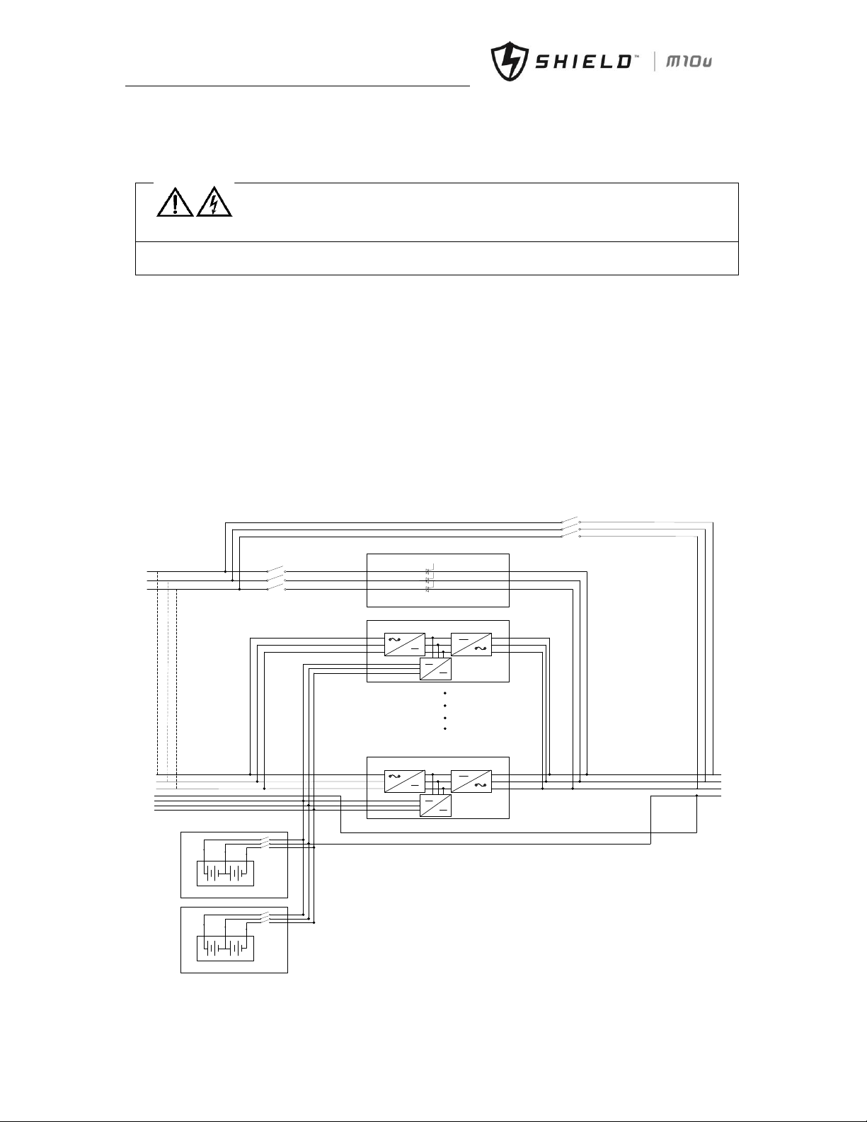
Chapter 5 Operations
30 Shield M10U user manual
Chapter 5 Operations
Warning: Hazardous mains voltage and/or battery voltage present(s) behind the protective
cover
The components that can only be accessed by opening the protective cover with tools cannot be operated by user.
Only qualified service personnel are authorized to remove such covers.
5.1 Introduction
The Modular UPS rack system provides the critical load (such as communication and data processing equipment) with
high quality uninterruptible AC power. The power from the UPS is free from voltage and frequency variations and
disturbances (interruption and spike) experienced at the Mains AC input supply.
This is achieved through high frequency double conversion power pulse width modulation (PWM) associated with fully
digital signal processing control (DSP), which features high reliability and convenience for use.
As shown in fig.5-1, the AC input mains source is supplied at UPS input and converted into a DC source. This DC source
feeds the Inverter that converts the DC source into a clean and input independent AC source. The battery powers the
load through the inverter in case of an AC input mains power failure. The utility source can also power the load through
the static bypass.
When the UPS needs maintenance or repair, the load can be transferred to maintenance bypass without interruption and
the power module and bypass module can be removed for maintenance.
REC INV
BAT
CHARGER
REC INV
BAT
CHARGER
BCB
Battery Module
BCB
bA
bB
bC
mA
mB
mC
mN
Batt+
BattN
Batt-
oA
oB
oC
oN
Power Module 1#
Power Module 10#
Bypass Module
manual Bypass(Q2)
Bypass(Q1)(not in
90kVA)
Fig.5- 1: Single Unit Block Diagram
警告
危险
Page 40
Chapter 5 Operations
Shield M10U user manual 31
5.1.1 Split-Bypass Input
Fig. 5-1 illustrates the Modular UPS in what is known as the split-bypass configuration (that is, the bypass uses a separated
AC power). In this configuration, the static bypass and maintenance bypass share the same independent bypass power
supply and connect to the power supply through a separate switch. Where a separated power source is not available, the
bypass and rectifier input supply connections are linked.
5.1.2 Static Transfer Switch
The circuit blocks labeled Static Switch in fig.5-1 contain electronically controlled switching circuits that enable the critical
load to be connected to either the inverter output or to a bypass power source via the static bypass line. During normal
system operation the load is connected to the inverter; but in the event of a UPS overload or inverter failure, the load is
automatically transferred to the static bypass line. To provide a clean (no-break) load transfer between the inverter
output and static bypass line, the inverter output and bypass supply must be fully synchronized during normal operating
conditions. This is achieved through the inverter control electronics, which makes the inverter frequency track that of
the static bypass supply, provided that the bypass remains within an acceptable frequency window.
A manually controlled maintenance bypass supply is incorporated into the UPS design. It enables the critical load to be
powered from the utility (bypass) supply while the UPS is shut down for routine maintenance.
Note
When the UPS is operating in bypass mode or on maintenance bypass, the connected equipment is not protected
from power failures or surges and sags.
5.2 1+1 Parallel System
Several “single unit” UPS modules may constitute a “1+1” system, where up to two single units operate together for the
purpose of providing additional power or reliability or both. The load is equally shared between any paralleled UPSs.
5.2.1 Features of Parallel System
1. The hardware and firmware of single module UPS units are completely compatible with the requirements of a parallel
system. Parallel configuration can be achieved merely through settings in configuration software. The parameters
settings for the modules in parallel system shall be consistent.
2. Parallel control cables are connected in a ring, providing both performance and redundancy. Dual-bus control cables
are connected between any two UPS modules of each bus. The intelligent paralleling logic provides the user with
maximum flexibility. For example, shutting down or starting up UPS modules in a parallel system can be done in any
sequence. Transfers between Normal and Bypass modes of operation are synchronized and self–recovering e.g. following
overloads and their clearance.
3. The total load of the parallel system can be queried from each unit’s LCD.
5.2.2 Parallel Requirements of UPS Modules
A group of paralleled modules behave as if it were one large UPS with the advantage of presenting higher reliability. In
order to assure that all modules are equally utilized and to comply with relevant wiring rules, the following requirements
apply:
1. All UPS modules shall be of the same rating and must be connected to the same bypass source.
2. The bypass and the main input sources must be referenced to the same neutral potential.
3. Any RCD (Residual Current detecting device), if installed, must be of an appropriate setting and located upstream of
the common neutral bonding point. Alternatively, the device must monitor the protective earth currents of the system.
Refer to the High Leakage Current Warning in the first part of this manual.
4. The outputs of all UPS modules must be connected to a common output bus.
5. It is strongly recommended that each paralleled UPS install at least a redundant power module
Note
警告
危险
警告
危险
Page 41

Chapter 5 Operations
32 Shield M10U user manual
1. Optional isolation transformers are available for applications where sources do not share the same neutral
reference or where the neutral is not available.
2. Parallel system is available only for 6 power modules cabinet.
5.3 Operating Mode
The Modular UPS is an on-line, double-conversion, reverse-transfer UPS that permits operation in these modes:
Normal mode
Battery Mode
Auto-restart mode
Bypass mode
Maintenance mode (manual bypass)
Parallel redundancy mode(6 modules cabinet)
ECO Mode
5.3.1 Normal Mode
The UPS inverter power modules continuously supplies the critical AC load. The rectifier/charger derives power from the
AC mains input source and supplies DC power to the inverter while simultaneously FLOAT or BOOST charging its
associated backup battery.
5.3.2 Battery Mode
Upon failure of the AC mains input power; the inverter power modules, which obtains power from the battery, supplies
the critical AC load. There is no interruption in power to the critical load upon failure. After restoration of the AC mains
input power, the “Normal Mode” operation will continue automatically without the necessity of user intervention.
5.3.3 Auto-Restart Mode
The battery may become exhausted following an extended AC mains failure. The inverter shuts down when the battery
reaches the End of Discharge voltage (EOD). The UPS may be programmed to “Auto Recovery after EOD” after a delay
time if the AC mains recovers. This mode and any delay time are programmed by the commissioning engineer.
5.3.4 Bypass Mode
If the inverter overload capacity is exceeded under normal mode, or if the inverter becomes unavailable for any reason,
the static transfer switch will perform a transfer of the load from the inverter to the bypass source, with no interruption
in power to the critical AC load. Should the inverter be asynchronous with the bypass, the static switch will perform a
transfer of the load from the inverter to the bypass with power interruption to the load. This is to avoid large cross
currents due to the paralleling of unsynchronized AC sources. This interruption is programmable but typically set to be
less than 3/4 of an electrical cycle, e.g., less than 15ms (50Hz) or less than 12.5ms (60Hz).
5.3.5 Maintenance Mode (Manual Bypass)
A manual bypass switch is available to ensure continuity of supply to the critical load when the UPS becomes unavailable
e.g. during a maintenance procedure.
5.3.6 Parallel Redundancy Mode (System Expansion)
For higher capacity or higher reliability or both, the outputs of several UPS modules can be programmed for direct
parallel while a built-in parallel controller in each UPS ensures automatic load sharing.
5.3.7 Eco Mode
To improve system efficiency, UPS rack system works in bypass mode at normal time, and inverter is standby. When utility
fails, UPS transfer to battery mode, and inverter power the loads. The efficiency of ECO system can be up to 98%.
NOTE: There is a short interruption time (lower than 10ms) when transfer from ECO mode to battery mode, it must be
sure that the time has no effect on loads.
Page 42

Chapter 5 Operations
Shield M10U user manual 33
5.4 Battery Management—Set During Commissioning
5.4.1 Normal Function
1. Constant Current Boost Charging
Current can be set up as 0%~20%, default setting is 10%.
2. Constant Voltage Boost Charging
Voltage of boost charging can be set as required by the type of battery.
For Valve Regulated Lead Acid (VRLA) batteries, maximum boost charge voltage should not exceed 2.4V / cell.
3. Float Charge
Voltage of float charging can be set as required by the type of battery.
For VRLA, float charge voltage should be between 2.2V to 2.3V, default setting is 2.25V.
4. Float Charge Temperature Compensation (optional)
A coefficient of temperature compensation can be set as required by the type of battery.
5. End of Discharge (EOD) Protection
If the battery voltage is lower than the EOD, the battery converter will shut down and the battery is isolated to avoid
further battery discharge. EOD is adjustable from 1.6V to 1.75V per cell (VRLA).
5.4.2 Advanced Functions (Software Settings Performed by the Commissioning Engineer)
Battery self-test and self-service
At periodic intervals, 25% of the rated capacity of the battery will be discharged automatically, and the actual load must
exceed 25% of the rated UPS (kVA) capacity. If the load is less than 25%, auto-discharge cannot be executed. The periodic
interval can be set from 720 to 3000 hours.
Conditions: Battery at float charge for at least 5 hours, load equal to 25~100% of rated UPS capacity Trigger—Manually
through the command of Battery Maintenance Test in LCD panel or automatically Battery self-test interval.
5.5 Battery Protection (Settings by Commissioning Engineer)
Battery Low Pre-warning
The battery undervoltage pre-warning occurs before the end of discharge. After this pre-warning, the battery should
have the capacity for 3 remaining minutes discharging with full load. And the
End of discharge (EOD) protection
If the battery voltage is lower than the EOD, the battery converter will be shut down. EOD is adjustable from 1.6V to
1.75V per cell (VRLA).
Battery Disconnect Devices Alarm
The alarm occurs when the battery disconnect device disconnects. The external battery connects to the UPS through the
external battery circuit breaker. The circuit breaker is manually closed and tripped by the UPS control circuit.
Page 43
Chapter 6 Operating Instructions
34 Shield M10U user manual
Chapter 6 Operating Instructions
Warning-Hazardous mains voltage and/or battery voltage present(s) behind the protective
cover
The components that can only be accessed by opening the protective cover with tools cannot be operated by user.
Only qualified service personnel are authorized to remove such covers.
6.1 Introduction
The Modular UPS operates in the following 3 modes listed in table.6-1. This section describes various kinds of operating
procedures under each operating mode, including transfer between operating modes, UPS setting and procedures for
turning on/off inverter.
Tab.6-1: UPS Operating mode
Operating mode
Descriptions
Normal mode
UPS powers the load
Bypass mode
The load power supply is provided by the static bypass. This mode can be regarded as a
temporary transition mode between the normal mode and maintenance bypass mode, or a
temporary abnormal operating status
Maintenance mode
UPS Shuts down, the load is connected to the mains via Maintenance bypass. NOTE: in this
mode the load is not protected against abnormal mains
Note:
1. Refer to Chapter 7 Operator Control and Display Panel, for all the user operating keys and LED displays.
2. The audible alarm may annunciate at various points in these procedures.
3. The UPS function can be set via maintenance software. However, the setting and commissioning must be done by
maintenance engineers trained.
6.1.1 Power Switches
The UPS rack system has a manual bypass breaker, a bypass input breaker, and all the other transfers are processed
automatically by internal control logics.
Customer must install an external mains input breaker, an external maintenance bypass breaker and an external output
breaker. An external bypass breaker is needed if split-bypass is applied for.
Note
It’s recommended that 4-poles breakers are used, and the rated current is higher than rated current of bypass breaker
in UPS. For 40KVA, 125A breakers are needed. For 20KVA, 63A breakers are needed.
6.2 UPS Startup
Do not start the UPS until the installation is completed, the system has been commissioned by authorized personnel and
the external power isolators are closed.
6.2.1 Start-Up Procedure
This procedure must be followed when turning on the UPS from a fully powered down condition.
The operating procedures are as follows:
1. Open the external power switch. Open the internal power switch. Open the UPS door, connect the power supply
cables and ensure the correct phase rotation.
警告
危险
警告
危险
Page 44
Chapter 6 Operating Instructions
Shield M10U user manual 35
Warning
During this procedure the UPS output terminals are live. If any load equipment are connected to the UPS output
terminals please check with the load user that it is safe to apply power: If the load is not ready to receive power then
ensure that it is safely isolated from the UPS output terminals.
2. Close external output circuit breaker. Close external mains input circuit breaker and connect the mains power.
The LCD starts up at this time. The Rectifier indicator flashes during the startup of rectifier. The rectifier enters
normal operation state, and after about 20s, the rectifier indicator goes steady green. After initialization, the bypass
static switch closes. The UPS Mimic LEDs will indicate as following:
LED
Status
Rectifier indicator
Green
Battery indicator
Red
Bypass indicator
Green
Inverter Indicator
Off
Load indicator
Green
Status indicator
Red
3. The inverter starts up automatically. The inverter indicator flashes during the startup of inverter. After about
1minute, the inverter is ready, the UPS transfers from bypass to inverter, the bypass indicator turns off, and the
inverter and load indicators turn on. The UPS is in normal mode. The UPS Mimic LEDs will indicate as following:
LED
Status
Rectifier indicator
Green
Battery indicator
Red
Bypass indicator
Off
Inverter Indicator
Green
Load indicator
Green
Status indicator
Red
4. Close external battery switch, battery indicator turns off, a few minutes later, the battery will be charged by UPS.
The UPS Mimic LEDs will indicates as following:
LED
Status
Rectifier indicator
Green
Battery indicator
Green
Bypass indicator
Off
Inverter Indicator
Green
Load indicator
Green
Status indicator
Green
Note
The panel on 6-power modules cabinet has 6 mimic indicators: rectifier, inverter, bypass, battery, load, status.
The panel on 2/4-power modules cabinet has only status LED.
6.2.2 Procedures for Switching Between Operation Modes
Switch from normal mode to bypass mode
Press “ ” menu in menu “operate” to switch to bypass mode.
Note
In bypass mode, the load is directly fed by the mains power instead of the pure AC power from the inverter.
Switch from bypass mode to normal mode
Press “ ” menu in bypass mode. After the inverter enters in normal operation, the UPS transfers to normal mode.
警告
危险
警告
危险
警告
危险
Page 45
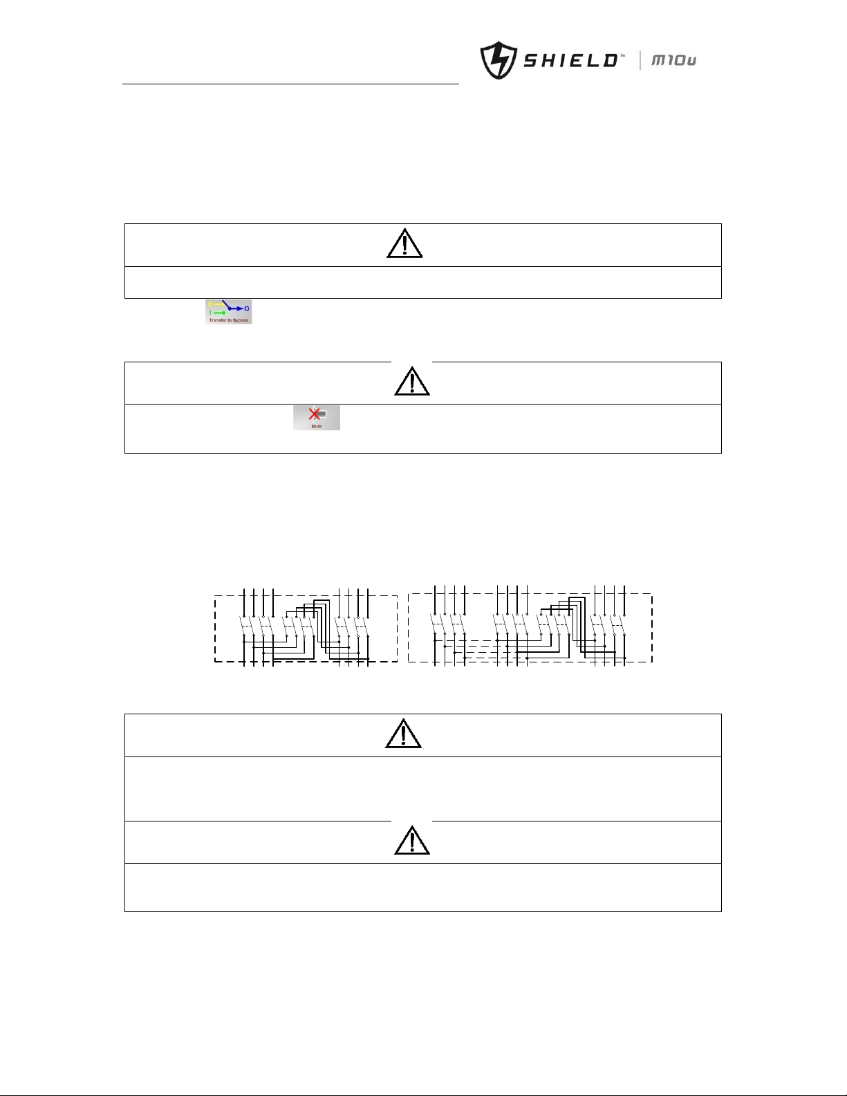
Chapter 6 Operating Instructions
36 Shield M10U user manual
6.3 Procedure for Switching the UPS between Maintenance Bypass and
Normal Mode
6.3.1 Procedure for Switching from Normal Mode to Maintenance Bypass Mode
This procedure can transfer the load from the UPS inverter output to the maintenance bypass supply, but the
precondition is that the UPS is in normal mode before the transfer.
Caution
Before making this operation, read messages on display to be sure that bypass supply is regular and the inverter is
synchronous with it, so as not to risk a short interruption in powering the load.
1. Press the “ ” menu in “operate” on the right side of the LCD.
The UPS Mimic indicator Inverter will green flash and also the Status Indicator will turn red and will be accompanied
by an audible alarm. The load transfers to static bypass, and the inverter standby.
Note
Pressing the mute off button in “operate” menu to cancel the audible alarm but leaves the warning
message displayed until the alarm condition is rectified.
2. Close the manual bypass breaker from OFF to ON position. The load power supply is provided by the manual bypass.
3. Press EPO to make sure the charge current is 0. Open the external battery breaker and internal battery breaker (if
built-in battery cabinet). Then power modules can be maintained.
4. If cabinet maintenance is needed, external maintenance bypass breaker is required. If external maintenance bypass
breaker is available, close external maintenance bypass breaker, open the external input breaker and external
output breaker, then UPS cabinet can be maintained. It’s recommended that external maintenance breaker are
installed as fig.6-1:
input
maintenance
output
AC utility To Load
UPS input
UPS output
input
maintenance
output
AC input2
To Load
UPS bypass
input
UPS output
UPS mains
input
bypass
AC input1
(a) Single input (b) split-bypass input
Fig.6- 1: External Maintenance Bypass
Warning
If you need to maintain the module, wait for 10 minutes to let the DC bus capacitor fully discharge before removing
corresponding module.
When the manual bypass switch is on position of ON, some part of the UPS circuit still has hazardous voltage.
Therefore, only qualified person can maintain the UPS.
Note
When the UPS is in maintenance bypass or manual bypass mode, the load is not protected against abnormal mains
supply.
There is no bypass breaker in 6 power modules cabinet.
6.3.2 Procedure for Switching from Maintenance Mode to Normal Mode
1. Close bypass breaker if available. Close manual bypass breaker. Close external output breaker. Close external mains
input breaker. The LCD starts up at this time. The rectifier indicator flashes during the startup of rectifier. The
警告
危险
警告
危险
警告
危险
警告
危险
Page 46
Chapter 6 Operating Instructions
Shield M10U user manual 37
rectifier enters normal operation state, and after about 20s, the rectifier indicator goes steady green. After
initialization, the bypass static switch closes and bypass indicator goes steady green.
2. Open the external maintenance breaker. Open manual bypass breaker.
Warning
Before opening the maintenance breaker, make sure that static bypass switch is working according power flow
displayed on LCD.
3. After about 60s, UPS transfers to inverter. Close external battery breaker and internal battery breaker (for battery
built-in cabinet).
6.3.3 Procedure for Switching from normal mode to manual bypass mode
1. Press the “ ” menu on the LCD. The UPS Mimic indicator Inverter will green flash and also the Status
Indicator will turn red and will be accompanied by an audible alarm. The load transfers to static bypass, and the inverter
standby.
2. Close manual bypass breaker to ON position. Open bypass breaker.
3. Press EPO button to ensure the battery current is 0. Open the battery circuit breaker or disconnect battery
terminals.
Warning
Make sure not to open external input breaker, otherwise, UPS output will be interrupted.
6.3.4 Procedures for Switching from manual bypass mode to normal mode
1. Press “ ” in function menu to clear EPO alarm.
2. Close bypass breaker and bypass indicator goes steady green.
3. Open manual bypass breaker.
4. Press the “ ” menu in bypass mode, UPS transfer to inverter after about 60s.
5. Close external battery circuit breaker or internal battery circuit breaker.
Warning
Before opening the manual breaker, make sure that static bypass switch is working according power flow displayed on
LCD.
6.4 Procedure for Completely Powering Down a UPS
If you need to power down the UPS completely, follow the procedures as:
Press EPO button on the front panel
Open external battery breaker and internal battery breaker
Open bypass breaker, external input breaker, external output breaker
If the rectifier and bypass use different power supply, you need to open these two input breakers respectively.
6.5 EPO Procedure
The EPO button is designed to switch off the UPS in emergency conditions (e.g., fire, flood, etc.).To achieve this, just press
the EPO button, and the system will turn off the rectifier, inverter and stop powering the load immediately (including the
inverter and bypass), and the battery stops charging or discharging.
If the input utility is present, the UPS control circuit will remain active; however, the output will be turned off. To
completely isolate the UPS, you need to open the mains input breaker and battery breaker.
警告
危险
警告
危险
警告
危险
Page 47
Chapter 6 Operating Instructions
38 Shield M10U user manual
6.6 Auto Start
Commonly, the UPS rack is start up on static bypass. When the mains power fails, the UPS draws power from the battery
system to supply the load until the battery voltage reaches the end of discharge (EOD) voltage, and the UPS will shut
down.
The UPS will automatically restart and enable output power:
After the mains power is restored
If the Auto Recovery after EOD Enabling feature is enabled
6.7 UPS Reset Procedure
After using EPO to shut down the UPS, operates as following to restore UPS:
Shutdown UPS completely
Start UPS as section 6.2.1
After the UPS is shut down due to inverter over temperature, or overload, or too many switching times, UPS will reset
the fault automatically when fault is cleared.
Note
The rectifier will be turned on automatically when the over temperature fault disappears after the disappearance of
over temperature signals.
After pressing the EPO button, if the UPS mains input has been disconnected, the UPS is completely powered down.
When the mains input is restored, the EPO condition will be cleared and the UPS system will enable static bypass mode
to restore the output.
Warning
If the maintenance bypass breaker is put to ON and the UPS has mains input, then the UPS output is energized.
6.8 Operation Instruction for Power Module Maintenance
Only a trained operator can perform the following procedures
Maintenance guidance for power modules
If the system is normal mode and the bypass is normal, the redundant number of power module is at least 1:
1. Enter in function menu and press “ ” to release shutdown power module function.
2. Press “off” button on the front panel of power module to manually power off power module.
3. Remove decorative metal strip on two sides and loose the screws of the power module, then remove the module
after 5 minutes.
If there are no redundant power modules:
1. Enter in function menu and press “ ” to transfer to bypass mode.
2. Remove decorative metal strip on both sides and loose the screws of the power module, then remove the module
after 5 minutes.
Note
To ensure the safety, be sure to use a multi-meter to measure the DC bus capacitor voltage and ensure the voltage is
below 60V before operation.
3. After finishing the maintenance of the power module, insert the main power module (the inserting interval for each
module is longer than 10s), the power module will automatically join the system operation, and then tighten the
screws at two sides of the power module.
4. Fix the decorative metal strip to cover screws on both sides of front panel.
Maintenance guidance for bypass power module
警告
危险
警告
危险
警告
危险
Page 48
Chapter 6 Operating Instructions
Shield M10U user manual 39
Note
The bypass power module cannot be maintained in battery mode.
If the system is in normal mode and the bypass is normal:
1. Manually shut down the inverter, and the UPS transfers to bypass. Close the manual bypass breaker and the UPS
transfer to manual bypass. Open the bypass breaker to shutdown bypass.
2. Press EPO button to ensure the battery current is 0. Open the battery circuit breaker or disconnect battery terminals.
3. Remove the bypass power modules that need maintenance or repair, wait for 5 minutes and then maintain the
bypass power modules. After finishing the maintenance of the bypass power modules, insert the modules.
4. Transfer to normal mode as section 6.3.2.
Note
The terminal of bypass power module is big, and it need more power when inserting bypass module to make sure
tighten connection.
6.9 Language Selection
The LCD menus and data display are available in 7 languages: Simple Chinese, English, Traditional Chinese, Turkish,
Russian, Polish, Portuguese.
Perform the following procedure to select a language needed:
1. In main menu, press “ ” to enter in setting menu on the LCD screen.
2. Select LANGUAGE menu.
3. Select the language. At this time, all the words in the LCD will be displayed in the selected language.
6.10 Changing the Current Date and Time
To change system date and time:
1. In main menu, press “ ” to enter in function setting menu in the LCD screen.
2. Select DATE&TIME.
3. Enter new date and time, then enter to confirm it.
6.11 Control Password 1
The system is password protected to limit the operator’s operating and control authorities. You can only operate and
test the UPS and battery after entering correct password 1. The default password 1 is 1203.
警告
危险
警告
危险
Page 49
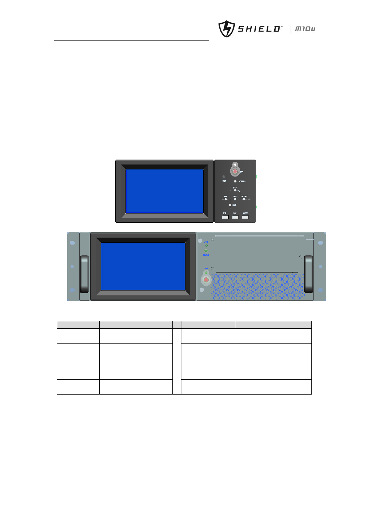
Chapter 7 Operator Control and Display Panel
40 Shield M10U user manual
Chapter 7 Operator Control and Display Panel
This chapter introduces the functions and operation instructions of the UPS operator control and display panel in
detail, and provides LCD display information, including LCD display types, detailed menu information, prompt
window information and UPS alarm list.
7.1 Introduction
The operator control and display panel is located on the front panel of the UPS. Through the LCD panel, the operator
can operate and control the UPS, and check all measured parameters, UPS and battery status, event and history logs.
The operator control panel is divided into three functional areas as shown in fig.7-1: mimic current path, LCD display
& Menu, control and operation button. The detailed description of control and display panel is shown in table.7-1.
(a) 3-modules and 6-modules cabinet
(b) 2-modules and 4-modules cabinet
Fig.7- 1: UPS operator control and display panel
Table.7- 1: Description of UPS Operator Control and Display Panel
Indicator
Function
Button
Function
REC
Rectifier indicator(60kVA)
EPO
EPO (emergency power off)
BAT
Battery indicator(60kVA)
HOME
Back to main menu(90kVA)
BYP
Bypass indicator(60kVA)
Left arrow
Right arrow
Select main menu items;
switch between submenu;
increase or reduce for number
input(90kVA)
INV
Inverter indicator(60kVA)
ENTER
Confirm(90kVA)
OUTPUT
Load indicator(60kVA)
STATUS
Status indicator
Page 50

Chapt
er 7 Operator Control and Display Panel
Shield M10U user manual 41
7.1.1 Mimic Current Path
The LEDs shown on the mimic current path represent the various UPS power paths and show the current UPS operating
status. The status description of indicators is shown in table.7-2.
Table.7- 2: Status Description of Indicator
Indicator
State
Description
Rectifier
indicator
Steady green
Rectifier of all modules is normal
Flashing green
At least one of module rectifier is starting
Steady red
At least one Rectifier of module fault
Flashing red
Main input of at least one module is abnormal
Off
Rectifier is not working
Battery
indicator
Steady green
Battery is charging
Flashing green
Battery is discharging
Steady red
Battery is abnormal (battery failure, no battery or battery reverse) or battery
converter is abnormal (failure, over current or over temperature) , EOD
Flashing red
Battery voltage is low
Off
Battery and battery converter is normal, battery is not charging
Bypass
indicator
Steady green
UPS is working in bypass mode
Steady red
Bypass is failure
Flashing red
Bypass voltage is abnormal
Off
Bypass is normal and is not working
Inverter
indicator
Steady green
Inverter is feeding the load
Flashing green
Inverter is starting, or UPS is working in ECO mode
Steady red
At least one module’s inverter is failure, and inverter is not feeding the load
Flashing red
Inverter is feeding load, and at least one module’s inverter is failure
Off
Inverter is not working in all modules
Load
indicator
Steady green
UPS output is on and is normal
Steady red
UPS output is overload and time is over, or output is shorten, or output has no
power supply
Flashing red
UPS is overload
Off
No output voltage
Status
indicator
Steady green
Normal operation
Steady red
Fault
7.1.2 Audible Alarm (buzzer)
There are two different types of audible alarm during UPS operation as shown in table.7-3.
Table.7- 3: Description of Audible Alarm
Alarm
Purpose
Two short, one long
when system has general alarm (for example: main input abnormal), this audible
alarm can be heard
Continuous alarm
When system has serious faults (for example: fuse or hardware fault), this audible
alarm can be heard
7.1.3 Functional Keys
There are 4 functional buttons on operator control and display panel, which are used together with LCD. The functions
description is shown in table.7-4.
Table.7- 4: Functions of Functional Keys
Functional key
Functions
EPO
To cut off the load power to shut down the rectifier, inverter, static bypass and
battery
HOME
To return the main menu
Left arrow and righ arrow
Select options in the mian menu, switch over secondary meun pages, upward
and downward roll the histrical log, add and subtract the intered number
Page 51
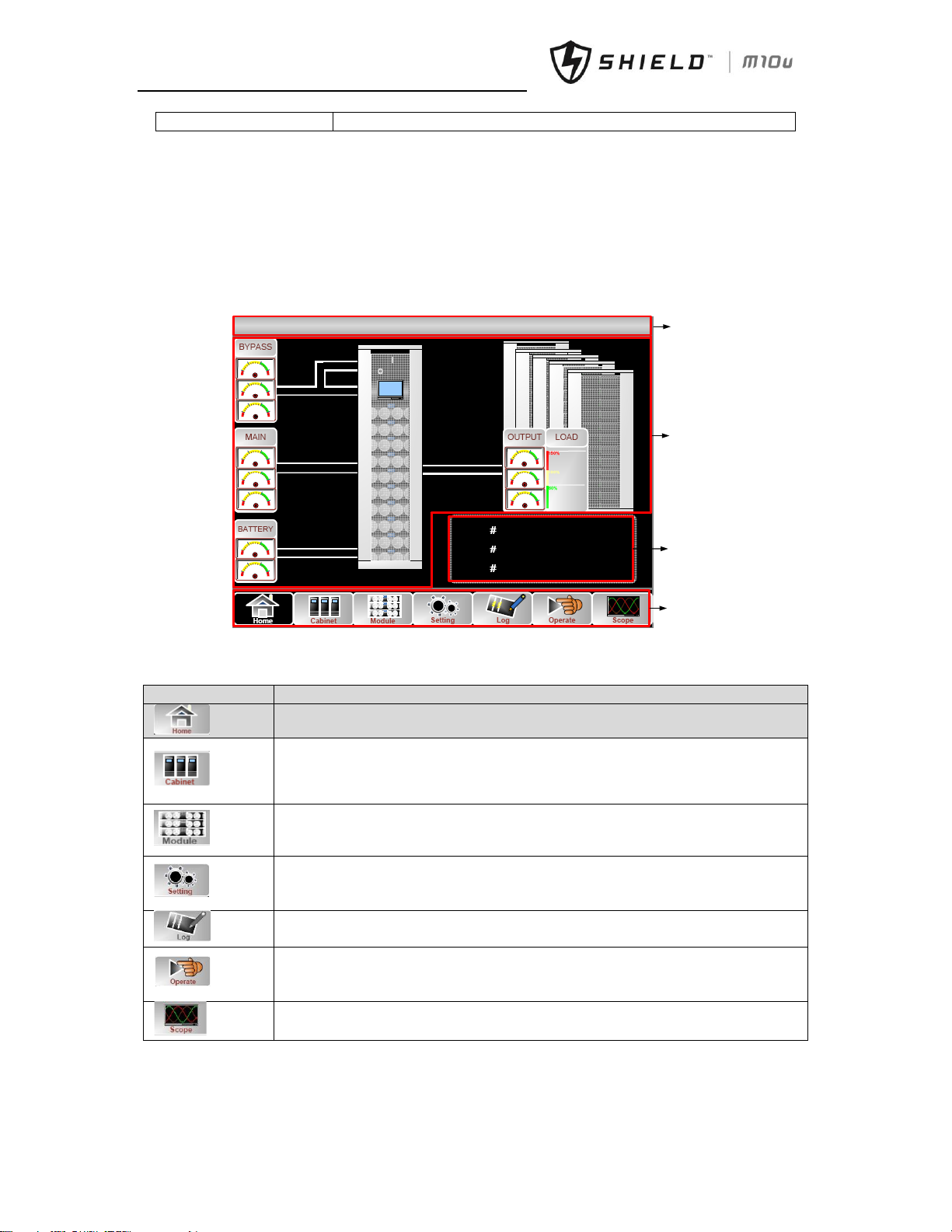
Chapter 7 Operator Control and Display Panel
42 Shield M10U user manual
Enter
confirm
7.1.4 Battery Pack Indicator
The LED on the front panel of battery pack indicates battery pack status. If battery fuse in battery pack is broken, LED
changes to be red. Customer must contactor with our local distributer to maintain it.
7.2 LCD Display Type
Following the self-check of UPS LCD display, the main LCD display is shown as fig.7-2, which can be divided into 4 display
windows: system information, power path, current record and main menu.
300/30 N=01 (S) 11:03
Battery Not Connected-Set
…………………………
1 0
2 0
3 0
System
information
……………………
……………………
……………………
…………………………
Power path
Current
warning
Main menu
Fig.7- 2: Main LCD Display
The description of LCD icon is shown in table.7-5:
Table.7- 5: Description of LCD Icons
Icon
Description
Return to main menu page
Bypass, main, output (voltage, current, PF, frequency), battery information(capacity,
remained time, worked days, battery temperature, ambient temperature), load
information(percent, active load, reactive load, apparent load)
Information of power module(main, output, load, S-code, module information)
DATE&TIME, LAGNUAGE, COMMUNICATION, USER(use user password 1), BATTERY set,
SERVICE set, RATE set, CONFIGURE
History LOG
Mute ON/OFF, Fault clear, transfer to bypass, transfer to inverter, enable module “off”, reset
battery history data, reset dust filter using time, battery test, battery maintenance, battery
boost, battery float, stop test
Scope of output voltage, output current, bypass voltage
The LCD menu tree is shown as below. Please refer to table. 7-7: Item Description of UPS Menu
Page 52
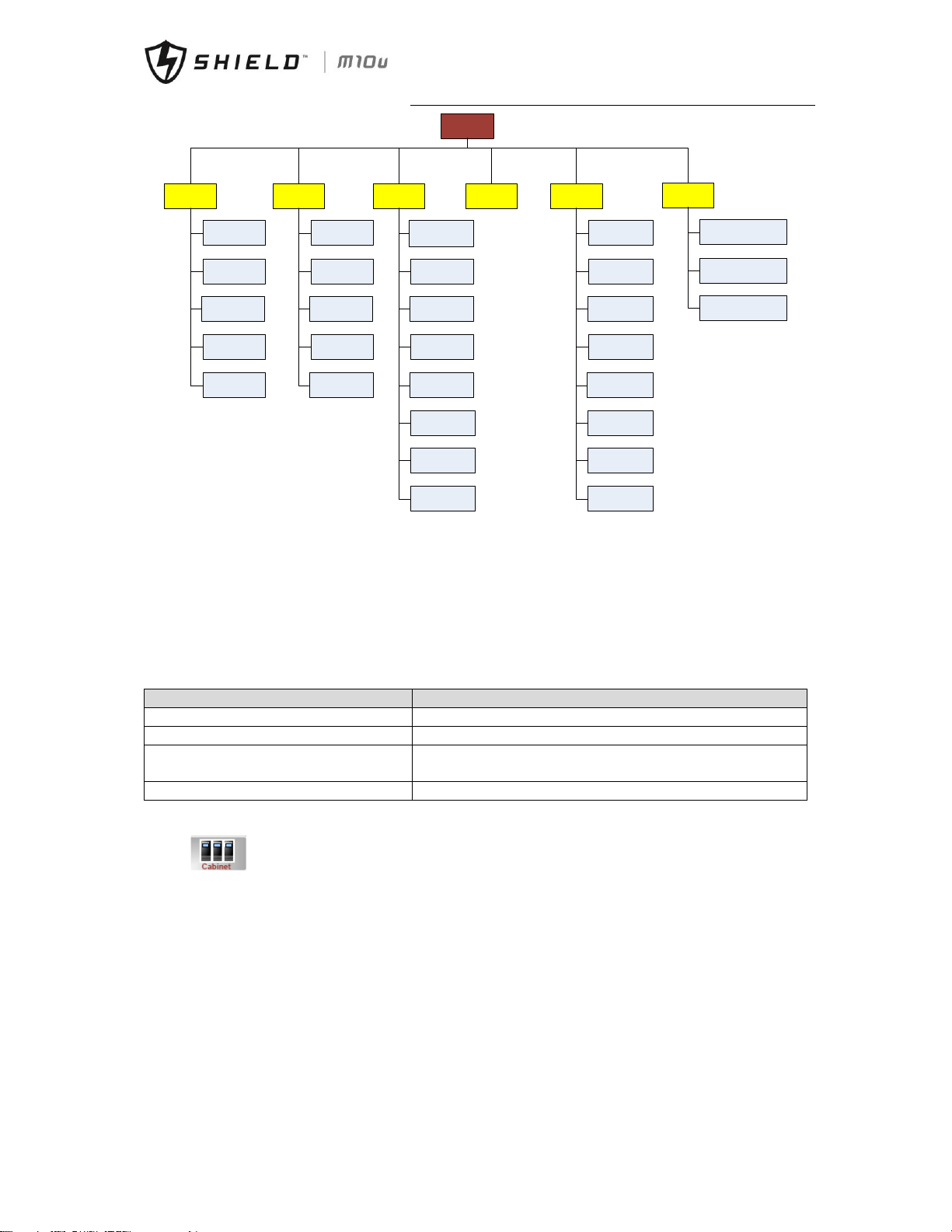
Chapt
er 7 Operator Control and Display Panel
Shield M10U user manual 43
Home
Cabinet Module Setting Log Operate
Scope
Bypass
Main
Output
Load
Battery
Input
Output
Load
Info.
S-code
Date &Time
Language
Comm.
User
Battery
Service
Rate
Configure
Mute
Fault clear
Transfer to
Bypass
Transfer to
Inverter
Battery
Test
Battery
Maintenance
Battery
Boost
Battery
Float
Output Voltage
Output Current
Bypass Voltage
Fig.7- 3: Menu Structure
7.3 Detailed Description of Menu Items
The LCD main display shown in fig.7-2 is described in details below.
UPS system information window
UPS information window: unit model, module numbers, unit mode, current date and time are displayed. The information
of the window is not necessary for the user to operate. The information of this window is given in table.7-6.
Table.7- 6: Description of Items in UPS System Information Window
Display contents
Meaning
300/30
Unit model: 300—unit capacity, 30—power modules capacity
N=01
1 Power module in system
(s)
Unit mode: S--single unit, P-0/1--parallel mode, E--ECO mode, L--LBS
mode, PE-0/1--parallel ECO mode, PL-0/1--parallel LBS mode
11:03
Date and time
Main menu window
Details of UPS menu is shown in Table.7-5.
Enter in to get cabinet information.
Page 53
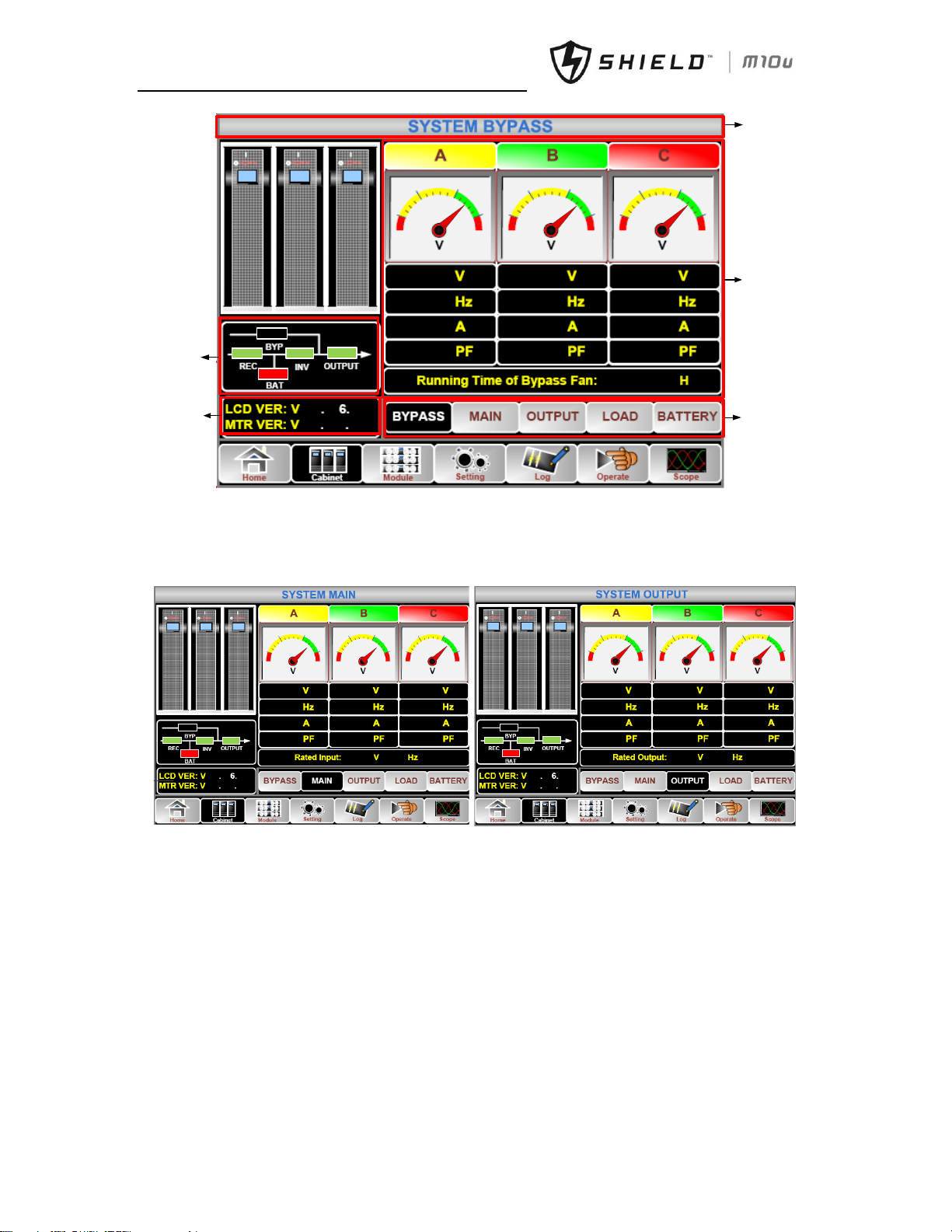
Chapter 7 Operator Control and Display Panel
44 Shield M10U user manual
0
50
100
180
260
300
0
50
100
180
300
220.5
221.6
49.99
49.99
0.0
0.0
0.00
0.00
57
55
0
513
0
Submenu
Version
information
Information
display
Title
Running
status
221.3
49.99
0.0
0.00
0
100
180
300
50
120
Fig.7- 4: cabinet menu
Submenu BYPASS, MAIN, OUTPUT
Bypass information, main input and output information (voltage, current, frequency, PF) are displayed in cabinet menu,
voltage is also shown in meter type. Current mimic status indicators, LCD and monitoring version are displayed. Shown
as below:
0
50
100
180
260
300
0
50
100
180
260
300
0
50
100
180
300
223.5
224.6
225.3
49.99 49.99 49.99
0.0
0.0
0.0
0.00
0.00 0.00
50
57
55
0
513
0
220
0
50
260
300
0
50
260
300
0
50
300
220.0 220.2
220.3
49.99
49.99 49.99
0.0 0.0
0.0
0.00 0.00 0.00
50
57
55
0 513
0
220
(a) Main input information (b) output information
Fig.7- 5: main input and output information
Submenu LOAD, BATTERY
Load information includes load percent, active load, reactive load, apparent load. Battery information includes battery
number, battery voltage, battery current, remained capacity, remained discharge time, discharge times, working days,
discharge hours, battery temperature (optional), ambient temperature (optional). Shown as below:
Page 54
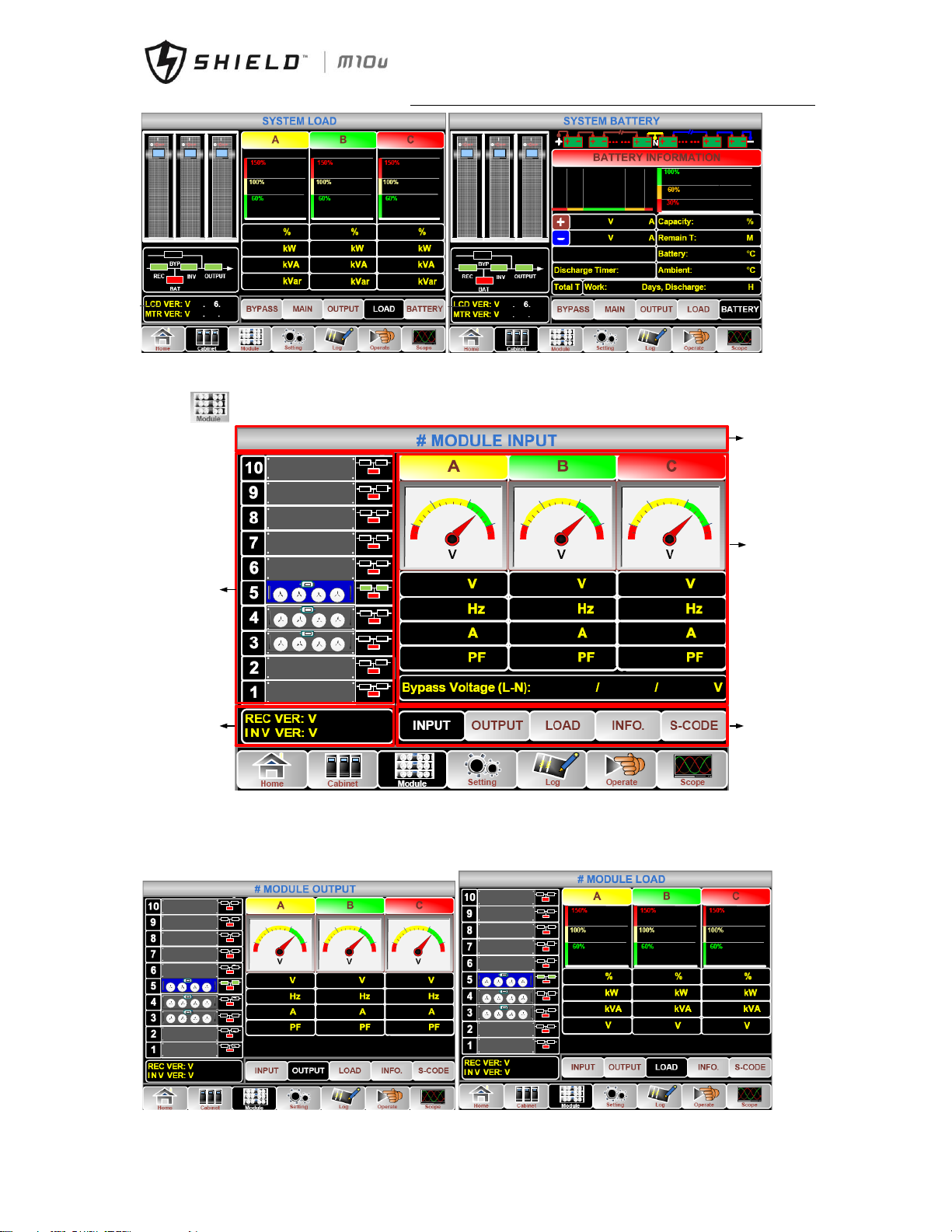
Chapt
er 7 Operator Control and Display Panel
Shield M10U user manual 45
5.0 6.0 2.5
0.0 0.0 0.0
0.5 0.6 0.2
57
550513
0
0.6
0.4 0.2
57
55 0 513
0
0.0
0.0
0.0
0.0
22
0.0 0.0
0.0
0.0
25.0
25.0
(a) system load information (b) system battery information
Fig.7- 6: load and battery information
Enter in to get power module information
5
220.6 220.3
50.00 50.01
1.5 2.1
0.42
0.32
220.4
Power module
information
Version
information
33.0.051
33.0.053
Title
Submenu
0
50
100
180
260
300
0
50
100
180
260
300
Information
display
220.5
50.01
2.1
0.31
0
50
100
180
220.6 220.6
Fig.7- 7: power module information
Module information menu includes: input, output, load, internal information, S-code, software version.
Submenu INPUT, OUTPUT, LOAD
Input and output information include voltage, current, frequency, PF. Load information includes load percent, active load,
reactive load, apparent load. Shown as below:
5
220.6 220.3
220.9
50.00 50.01 50.00
1.5 2.1
2.0
0.42
0.32 0.46
33.0.051
33.0.053
0
50
100
180
260
300
0
50
100
180
260
300
0
50
100
180
300
260
5
0.0
0.0 0.0
0.0
0.0 0.0
0.0 0.0
0.0
221.0
222.5 222.5
33.0.051
33.0.053
Page 55
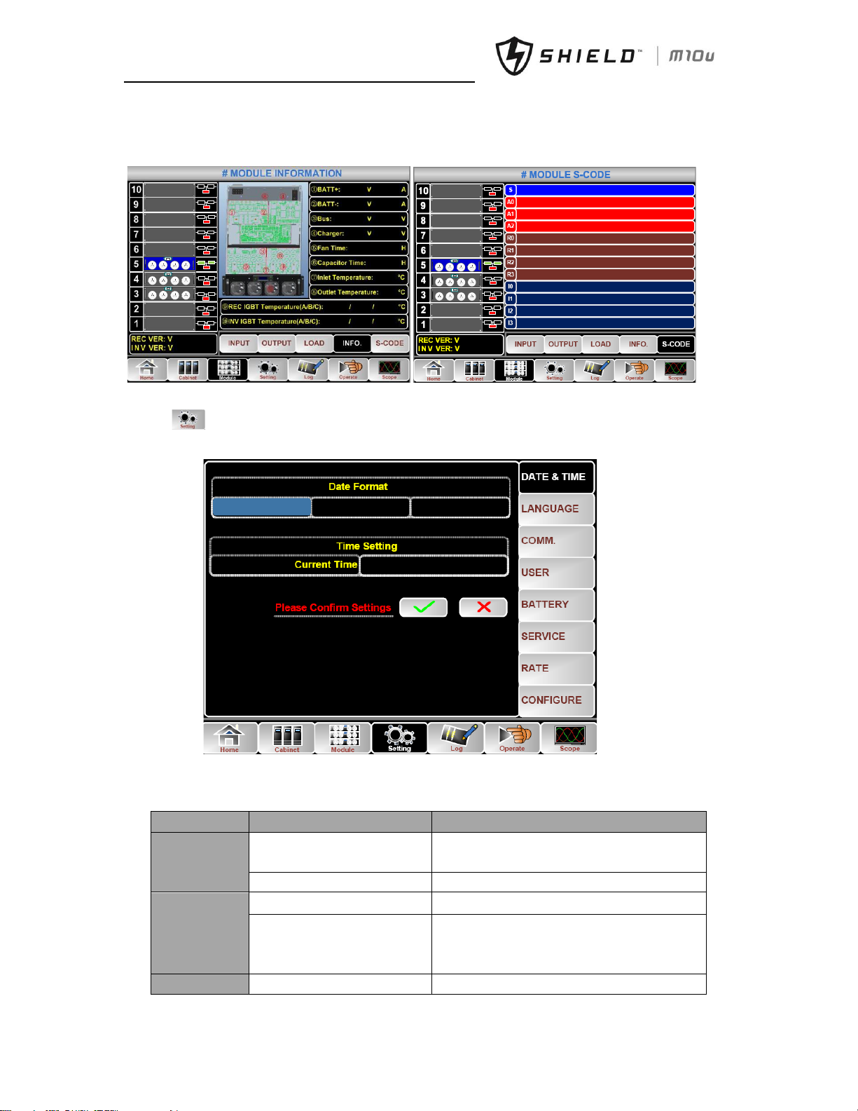
Chapter 7 Operator Control and Display Panel
46 Shield M10U user manual
(a) module output information (b) module load information
Fig.7- 8: module output and load information
Submenu INFO., S-Code
INFO menu includes modules battery information, inlet temperature, outlet temperature, IGBT temperature. And S-code
menu displays S-code of power module to indicate what has happened to power module.
33.0.051
33.0.053
0.0 0.0
0.0
0.0
400.4 398.9
0.0 0.0
0
0
21.0
23.3
22.5 20.0 20.0
25.0 20.0 25.0
5
33.0.051
33.0.053
5
1221 -0001 -0000 -0120 0000 -0000 -1102 -1000
0000 -0000 -0000 -0000 0000 -0000 -0000 -0000
0000 -0000 -0000 -0000 0000 -0000 -0000 -0000
0000 -0000 -0000 -0000 0000 -0000 -0000 -0000
1221 -0001 -0000 -0120 1000 -1101 -1111 -1111
0000 -0000 -0000 -0000 0000 -0000 -0000 -0000
0000 -0000 -0000 -0000 0000 -0000 -0000 -0000
0000 -0000 -0000 -0000 0000 -0000 -0000 -0000
1111 -1111 -1111 -1111 1111 -1011 -1111 -1111
0000 -0000 -0000 -0000 0000 -0000 -0000 -0000
0000 -0000 -0000 -0000 0000 -0000 -0000 -1000
0000 -0000 -0000 -1000 0000 -0011 -1100 -0100
(a) module information (b) S-code of the power module
Fig.7- 9: module information and S-code
Enter in to set UPS system.
It includes DATE&TIME, LANGUAGE, COMM., USER, BATTERY, SERVICE, RATE, CONFIGURE. And submenu BATTERY,
SERVICE, RATE, CONFIGURE is only available for service engineer or manufacturer.
MM-DD-YY DD-MM-YY
YY-MM-DD
2014-02-14 11:28:42
Fig.7- 10: Setting Menu
Table.7- 7: description of details of submenu in setting
Submenu Name
Contents
Meaning
Date&Time
Date format setting
Three format: (a) year/month/day,(b)
moth/date/year,(c) date/month/year
Time setting
Setting time
Language
Current language
Language in use
Language selection
Simplified Chinese and English selectable(The
setting taking action immediately after touching
the language icon)
COMM.
Device Address
Setting the communication address
Page 56
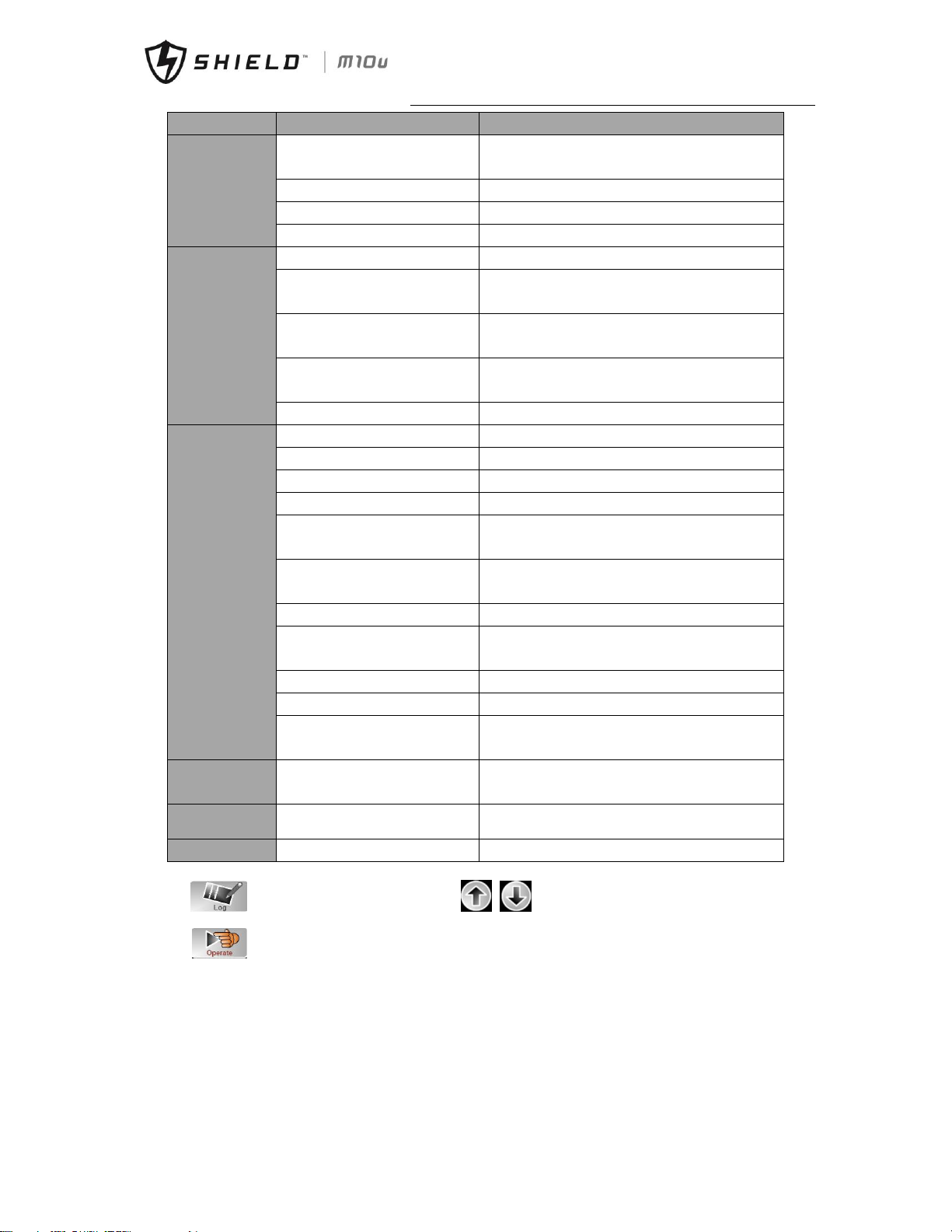
Chapt
er 7 Operator Control and Display Panel
Shield M10U user manual 47
Submenu Name
Contents
Meaning
RS232 Protocol Selection
SNT Protocol, ModBus Protocol, YD/T Protocol and
Dwin(For factory use)
Baudrate
Setting the baudrate of SNT, ModBus and YD/T
Modbus Mode
Setting mode for Modbus:ASCII and RTU selectable
Modbus parity
Setting the parity for Modbus
USER
Output voltage Adjustment
Setting the Output Voltage
Bypass Voltage Up Limited
Up limited working Voltage for Bypass
,
settable:+10%,+15%,+20%,+25%
Bypass Voltage Down Limited
Down limited working Voltage for Bypass,
settable:-10%,-15%,-20%,-30%,-40%
Bypass Frequency Limited
Permitted working Frequency for Bypass
Settable:+-1Hz,+-3Hz,+-5Hz
Dust Filter Maintenance Period
Setting Dust Filter Maintenance Period
BATTERY
Battery Number
Setting the number of the battery(12V)
Battery Capacity
Setting of the AH of the battery
Float Charge Voltage/Cell
Setting the floating Voltage for battery cell(2V)
Boost Charge Voltage/Cell
Setting the boost Voltage for battery cell(2V)
EOD(End of charge)
Voltage/Cell,@0.6C Current
EOD voltage for cell battery,@0.6C
EOD(End of charge)
Voltage/Cell,@0.15C Current
EOD voltage for cell battery,@0.15C
Charge Current Percent Limit
Charge current (percentage of the rated current)
Battery Temperature
Compensate
Coefficient for battery temperature compensation
Boost Charge Time Limit
Setting boost charging time
Auto Boost Period
Setting the auto boost period
Auto Maintenance Discharge
Period
Setting the period for auto maintenance discharge
SERVICE
System Mode
Setting the system mode: Single ,parallel, Single
ECO, parallel ECO,LBS, parallel LBS
RATE
Configure the rated Parameter
For the factory use
CONFIGURE
Configure the system
For the factory use
Enter in to get history log of UPS system. Use to scroll the list.
Enter in to control UPS system. The function and test command are shown as below:
Page 57
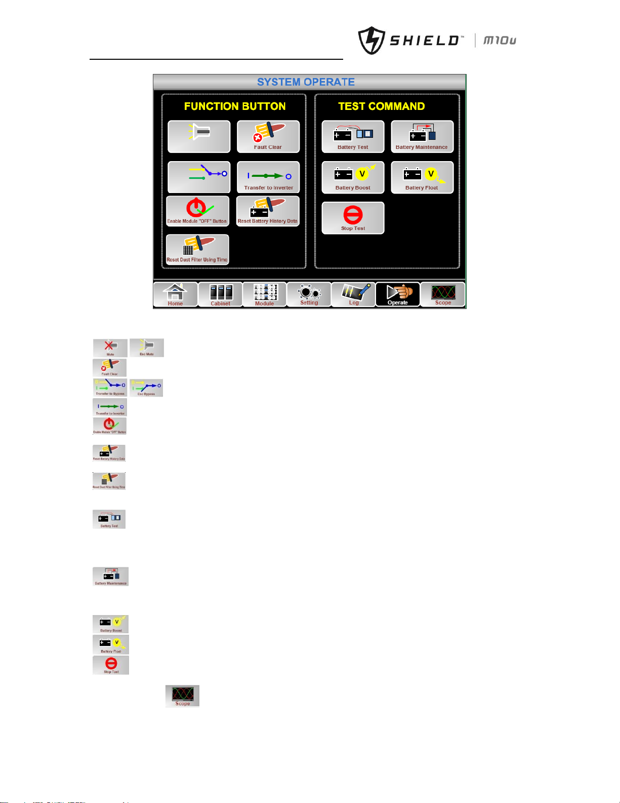
Chapter 7 Operator Control and Display Panel
48 Shield M10U user manual
ESC Mute
Transfer to Bypass
B
I
Fig.7- 11: System Operate
Menu of Operate includes:
Functional operation
Mute off or mute on.
Fault clear manually
Manually transfer to bypass or escape from bypass mode
Transfer to inverter mode manually. The output could be interrupted.
Enable the “OFF” button on the front panel of power module. Then the “OFF” button is available, user can
press the button to shutdown the power module.
Reset battery history data including discharge dates and hours, discharge times. Normally reset battery
history data after replacing new batteries.
Reset dust filter data including days and maintenance period. Normally reset filter data after replacing new
filter or washing.
Command
Battery test command. UPS transfer to battery mode, main LED indicator is dark and battery LED indicator
green flashes. If battery is sick or battery is failure, UPS will alarm and transfer back to normal mode or transfer to bypass
mode. Make sure there is not any warns or alarm, make sure that battery voltage is higher than 90% of float voltage. If
battery is normal, UPS will transfer back to normal mode after 20 seconds. If battery test is failure, UPS alarms in the
history log.
Battery maintenance command. UPS transfer to battery mode, main LED indicator is dark and battery LED
indicator green flashes. Make sure that there is not any warns or alarm, make sure that battery voltage is higher than 90%
of float voltage. If battery is normal, UPS will transfer back to normal mode until battery voltage is down to 105% of EOD
voltage and then transfer back to normal mode.
Manually enable charger enter in boost charge mode to charge the batteries more quickly.
Manually enable charger enter in float charge mode.
Stop battery test or battery maintenance.
Enter in main menu to see the waveform of output voltage, current and bypass voltage.
Page 58
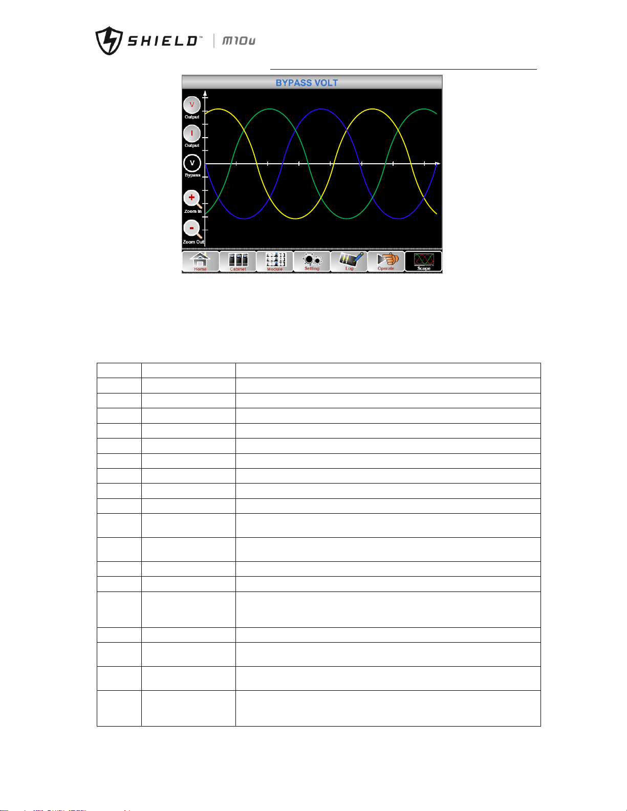
Chapt
er 7 Operator Control and Display Panel
Shield M10U user manual 49
220.2 220.0 220.1
Fig.7- 12: output and bypass waveform
7.4 UPS Event Log
The follow table.7-8 gives the complete list of all the UPS events displayed by history record window and current record
window.
Table.7- 8: UPS Event List
NO.
UPS events
Description
1
Fault Clear
Manually clear fault
2
Log Clear
Manually clear History log
3
Load On UPS
Inverter feeds load
4
Load On Bypass
Bypass feeds load
5
No Load
No load
6
Battery Boost
Charger is working in boost charging mode
7
Battery Float
Charger is working in float charging mode
8
Battery Discharge
Battery is discharging
9
Battery Connected
Battery is connected already
10
Battery Not
Connected
Battery is not yet connected.
11
Maintenance CB
Closed
Manual maintenance breaker is closed
12
Maintenance CB Open
Manual maintenance breaker is opened
13
EPO
Emergency Power Off
14
Module On Less
Available power module capacity is less then the load capacity. Please reduce
the load capacity or add extra power module to make sure that the UPS capacity
is big enough.
15
Generator Input
Generator is connected and a signal is sent to the UPS.
16
Utility Abnormal
Utility (Grid) is abnormal. Mains voltage or frequency exceeds the upper or lower
limit and results in rectifier shutdown. Check the input phase voltage of rectifier.
17
Bypass Sequence
Error
Bypass voltage Sequence is reverse. Check if input power cables are connected
correctly.
18
Bypass Volt Abnormal
This alarm is triggered by an inverter software routine when the amplitude or
frequency of bypass voltage exceeds the limit. The alarm will automatically reset
if the bypass voltage becomes normal.
Page 59

Chapter 7 Operator Control and Display Panel
50 Shield M10U user manual
First check if relevant alarm exists, such as “bypass circuit breaker open”, “Byp
Sequence Err” and “Ip Neutral Lost”. If there is any relevant alarm, first clear this
alarm.
1. Then check and confirm if the bypass voltage and frequency displayed on the
LCD are within the setting range. Note that the rated voltage and frequency are
respectively specified by “Output Voltage” and “Output Frequency”.
2. If the displayed voltage is abnormal, measure the actual bypass voltage and
frequency. If the measurement is abnormal, check the external bypass power
supply. If the alarm occurs frequently, use the configuration software to
increase the bypass high limit set point according to the user’s suggestions
19
Bypass Module Fail
Bypass Module Fails. This fault is locked until power off. Or bypass fans fail.
20
Bypass Module Over
Load
Bypass current is over the limitation. If bypass current is under 135% of the rated
current. The UPS alarms but has no action.
21
Bypass Over Load Tout
The bypass overload status continues and the overload times out.
22
Byp Freq Over Track
This alarm is triggered by an inverter software routine when the frequency of
bypass voltage exceeds the limit. The alarm will automatically reset if the bypass
voltage becomes normal.
First check if relevant alarm exists, such as “bypass circuit breaker open”, “Byp
Sequence Err” and “Ip Neutral Lost”. If there is any relevant alarm, first clear this
alarm.
1. Then check and confirm if the bypass frequency displayed on the LCD are
within the setting range. Note that the rated frequency are respectively
specified by “Output Frequency”.
2. If the displayed voltage is abnormal, measure the actual bypass frequency. If
the measurement is abnormal, check the external bypass power supply. If the
alarm occurs frequently, use the configuration software to increase the bypass
high limit set point according to the user’s suggestions
23
Exceed Tx Times Lmt
The load is on bypass because the output overload transfer and re-transfer is
fixed to the set times during the current hour. The system can recover
automatically and will transfer back to the inverter with 1 hour
24
Output Short Circuit
Output shorted Circuit.
Fist check and confirm if loads have something wrong.
Then check and confirm if there is something wrong with terminals, sockets or
some other power distribution unit.
If the fault is solved, press “Fault Clear” to restart UPS.
25
Battery EOD
Inverter turned off due to low battery voltage. Check the mains power failure
status and recover the mains power in time
26
Battery Test
System transfer to battery mode for 20 seconds to check if batteries are normal
27
Battery Test OK
Battery Test OK
28
Battery Maintenance
System transfer to battery mode until to be 1.1*EOD voltage to maintenance
battery string
29
Battery Maintenance
OK
Battery maintenance succeed
30
Module inserted
Power Module is inserted in system.
31
Module Exit
Power Module is pulled out from system.
32
Rectifier Fail
The N# Power Module Rectifier Fail, The rectifier is fault and results in rectifier
shutdown and battery discharging.
33
Inverter Fail
The N# Power Module Inverter Fail. The inverter output voltage is abnormal and
the load transfers to bypass.
34
Rectifier Over Temp.
The N# Power Module Rectifier Over Temperature. The temperature of the
rectifier IGBTs is too high to keep rectifier running. This alarm is triggered by the
signal from the temperature monitoring device mounted in the rectifier IGBTs.
The UPS recovers automatically after the over temperature signal disappears.
If over temperature exists, check:
Page 60

Chapt
er 7 Operator Control and Display Panel
Shield M10U user manual 51
1. Whether the ambient temperature is too high.
2. Whether the ventilation channel is blocked.
3. Whether fan fault happens.
4. Whether the input voltage is too low.
35
Fan Fail
At least one fan fails in the N# power module.
36
Output Over load
The N# Power Module Output Over Load. This alarm appears when the load rises
above 100% of nominal rating. The alarm automatically resets once the overload
condition is removed.
1. Check which phase has overload through the load (%) displayed in LCD so as
to confirm if this alarm is true.
2. If this alarm is true, measure the actual output current to confirm if the
displayed value is correct.
Disconnect non-critical load. In parallel system, this alarm will be triggered if the
load is severely imbalanced.
37
Inverter Overload
Tout
N# Power Module Inverter Over Load Timeout. The UPS overload status
continues and the overload times out.
Note:
The highest loaded phase will indicate overload timing-out first.
When the timer is active, then the alarm “unit over load” should also be active as
the load is above nominal.
When the time has expired, the inverter Switch is opened and the load
transferred to bypass.
If the load decreases to lower than 95%, after 2 minutes, the system will transfer
back to inverter mode. Check the load (%) displayed in LCD so as to confirm if
this alarm is true. If LCD displays that overload happens, then check the actual
load and confirm if the UPS has over load before alarm happens.
38
Inverter Over Temp.
The N# Power Module Inverter Over Temperature.
The temperature of the inverter heat sink is too high to keep inverter running.
This alarm is triggered by the signal from the temperature monitoring device
mounted in the inverter IGBTs. The UPS recovers automatically after the over
temperature signal disappears.
If over temperature exists, check:
Whether the ambient temperature is too high.
Whether the ventilation channel is blocked.
Whether fan fault happens.
Whether inverter overload time is out.
39
On UPS Inhibited
Inhibit system transfer from bypass to UPS (inverter). Check:
Whether the power module’s capacity is big enough for load.
Whether the rectifier is ready.
Whether the bypass voltage is normal.
40
Manual Transfer Byp
Transfer to bypass manually
41
Esc Manual Bypass
Escape from “transfer to bypass manually” command. If UPS has been
transferred to bypass manually, this command enable UPS to transfer to
inverter.
42
Battery Volt Low
Battery Voltage is Low. Before the end of discharging, battery voltage is low
warning should occur. After this pre-warning, battery should have the capacity
for 3 minutes discharging with full load.
43
Battery Reverse
Battery cables are connected not correctly.
44
Inverter Protect
The N# Power Module Inverter Protect. Check:
Whether inverter voltage is abnormal
Whether inverter voltage is much different from other modules, if yes, please
adjust inverter voltage of the power module separately.
45
Input Neutral Lost
The mains neutral wire is lost or not detected. For 3 phases UPS, it’s
recommended that user use a 3-poles breaker or switch between input power
and UPS.
Page 61

Chapter 7 Operator Control and Display Panel
52 Shield M10U user manual
46
Bypass Fan Fail
At least one of bypass module Fans Fails
47
Manual Shutdown
The N# Power Module is manually shutdown. The power module shuts down
rectifier and inverter, and there’s on inverter output.
48
Manual Boost Charge
Manually force the Charger work in boost charge mode.
49
Manual Float Charge
Manually force the charger work in float charge mode.
50
UPS Locked
Forbidden to shutdown UPS power module manually.
51
Parallel Cable Error
Parallel cables error. Check:
If one or more parallel cables are disconnected or not connected correctly
If parallel cable round is disconnected
If parallel cable is OK
52
Lost N+X Redundant
Lost N+X Redundant. There is no X redundant powers module in system.
53
EOD Sys Inhibited
System is inhibited to supply after the battery is EOD (end of discharging)
54
Battery Test Fail
Battery Test Fail. Check if UPS is normal and battery voltage is over 90% of float
voltage.
55
Battery Maintenance
Fail
Check
If UPS is normal and not any alarms
If the battery voltage is over 90% of float voltage
If load is over 25%
56
Ambient Over Temp
Ambient temperature is over the limit of UPS. Air conditioners are required to
regulate ambient temperature.
57
REC CAN Fail
Rectifier CAN bus communication is abnormal. Please check if communication
cables are not connected correctly.
58
INV IO CAN Fail
IO signal communication of inverter CAN bus is abnormal. Please check if
communication cables are not connected correctly.
59
INV DATA CAN Fail
DATA communication of inverter CAN bus is abnormal. Please check if
communication cables are not connected correctly.
60
Power Share Fail
The difference of two or more power modules’ output current in system is over
limitation. Please adjust output voltage of power modules and restart UPS.
61
Sync Pulse Fail
Synchronization signal between modules is abnormal. Please check if
communication cables are not connected correctly.
62
Input Volt Detect Fail
Input voltage of N# power module is abnormal.
Please check if the input cables are connected correctly.
Please check if input fuses are broken.
Please check if utility is normal.
63
Battery Volt Detect
Fail
Battery voltage is abnormal.
Please check if batteries are normal.
Please check if battery fuses are broken on input power board.
64
Output Volt Fail
Output voltage is abnormal.
65
Bypass Volt Detect Fail
Bypass voltage is abnormal.
Please check if bypass breaker is closed and is good.
Please check if bypass cables are connected correctly.
66
INV Bridge Fail
Inverter IGBTs are broken and opened.
67
Outlet Temp Error
Outlet temperature of power module is over the limitation.
Please check if fans are abnormal.
Please check if PFC or inverter inductors are abnormal.
Please check if air passage is blocked.
Please check if ambient temperature is too high.
68
Input Curr Unbalance
The difference of input current between every two phases is over 40% of rated
current.
Please check if rectifier’s fuses, diode, IGBT or PFC diodes are broken.
Please check if input voltage is abnormal.
69
DC Bus Over Volt
Voltage of DC bus capacitors is over limitation. UPS shutdown rectifier and
inverter.
Page 62

Chapt
er 7 Operator Control and Display Panel
Shield M10U user manual 53
70
REC Soft Start Fail
While soft start procedures are finished, DC bus voltage is lower than the
limitation of calculation according utility voltage. Please check
1. Whether rectifier diodes are broken
2. Whether PFC IGBTs are broken
3. Whether PFC diodes are broken
4. Whether drivers of SCR or IGBT are abnormal
5. Whether soft start resistors or relay are abnormal
71
Relay Connect Fail
Inverter relays are opened and cannot work or fuses are broken.
72
Relay Short Circuit
Inverter relays are shorted and cannot be released.
73
PWM Sync Fail
PWM synchronizing signal is abnormal
74
Intelligent Sleep
UPS works in intelligent sleep mode. In this mode, the power modules will be
standby in turn. It will be more reliability and higher efficiency. It must be
confirmed that remained power modules’ capacity is big enough to feed load. It
must be conformed that working modules’ capacity is big enough if user add
more load to UPS. It’s recommended that sleeping power modules are waken up
if the capacity of new added loads is not sure.
75
Manual Transfer to
INV
Manually transfer UPS to inverter. It’s used to transfer UPS to inverter when
bypass is over track. The interrupt time could be over 20ms.
76
Input Over Curr Tout
Input over current timeout and UPS transfer to battery mode.
Please check if input voltage is too low and output load is big. Please regulate
input voltage to be higher if it’s possible or disconnect some loads.
77
No Inlet Temp. Sensor
Inlet temperature sensor is not connected correctly.
78
No Outlet Temp.
Sensor
Outlet temperature sensor is not connected correctly.
79
Inlet Over Temp.
Inlet air is over temperature. Make sure that the operation temperature of UPS
is between 0-40°C.
80
Capacitor Time Reset
Reset timing of DC bus capacitors.
81
Fan Time Reset
Reset timing of fans.
82
Battery History Reset
Reset battery history data.
83
Byp Fan Time Reset
Reset timing of bypass fans.
84
Battery Over Temp.
Battery is over temperature. It’s optional.
85
Bypass Fan Expired
Working life of bypass fans is expired, and it’s recommended that the fans are
replaced with new fans. It must be activated via software.
86
Capacitor Expired
Working life of capacitors is expired, and it’s recommended that the capacitors
are replaced with new capacitors. It must be activated via software.
87
Fan Expired
Working life of power modules’ fans is expired, and it’s recommended that the
fans are replaced with new fans. It must be activated via software.
88
INV IGBT Driver Block
Inverter IGBTs are shutdown.
Please check if power modules are inserted in cabinet correctly.
Please check if fuses between rectifier and inverter are broken.
89
Battery Expired
Working life of batteries is expired, and it’s recommended that the batteries are
replaced with new batteries. It must be activated via software.
90
Bypass CAN Fail
The CAN bus between bypass module and cabinet is abnormal.
91
Dust Filter Expired
Dust filter need to be clear or replaced with a new one
92
Battery Test Fail
Battery test function is forbidden.
Please check if battery voltage is higher than
Please check if load is higher than 25%
Please check if battery connection is OK
93
Stop Test
Manually stop battery test or battery maintenance, UPS transfer back to normal
mode.
94
Wave Trigger
Waveform has been saved while UPS fail
95
Bypass CAN Fail
Bypass and cabinet communicate with each other via CAN bus. Check
Page 63

Chapter 7 Operator Control and Display Panel
54 Shield M10U user manual
If connector or signal cable is abnormal.
If monitoring board is abnormal.
96
Firmware Error
Manufacturer used only.
97
System Setting Error
Manufacturer used only.
98
Bypass Over Temp.
Bypass module is over temperature. Please check
If bypass load is overload
If ambient temperature is over 40°C
If bypass SCRs are assembled correctly
If bypass fans are normal
99
Module ID Duplicate
At least two modules are set as same ID on the power connector board, please
set the ID as correct sequence
Page 64
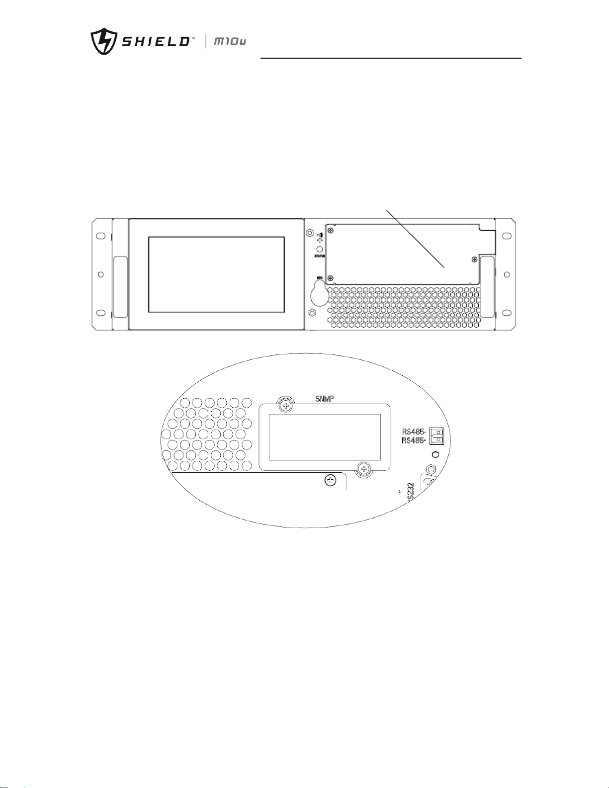
Chapter 8 Optional Parts
Shield M10U user manual 55
Chapter 8 Optional Parts
8.1 Install SNMP card
SNMP card is installed on the front panel of bypass module. To install SNMP card:
1. Remove the cover of intelligent slot (see Fig. 8-1).
2. Install SNMP card in the slot and tighten it with screws.
SNMP
a) 2 slots and 4 slots cabinet
b) 3/6 slots cabinet
Fig.8- 1: SNMP card
Page 65

Chapter 9 Product Specification
56 Shield M10U user manual
Chapter 9 Product Specification
This chapter provides UPS product specification.
9.1 Applicable Standards
The UPS has been designed to conform to the following European and international standards:
Table.9- 1: Compliance with European and International Standards
Item
Normative reference
General safety requirements for UPS used
in operator access areas
EN50091-1-1/IEC62040-1-1/AS 62040-1-1
Electromagnetic compatibility (EMC)
requirements for UPS
EN50091-2/IEC62040-2/AS 62040-2(C3)
Method of specifying the performance and
test requirements of UPS
EN50091-3/IEC62040-3/AS 62040-3(VFI SS 111)
Note: The above mentioned product standards incorporate relevant compliance clauses with generic IEC and EN
standards for safety (IEC/EN/AS60950), electromagnetic emission and immunity (IEC/EN/ AS61000 series) and
construction (IEC/EN/AS60146 series and 60950).
9.2 Environmental Characteristics
Table.9- 2: Environmental Properties
Items
Unit
Requirements
Acoustic noise level at 1 meter
dB
56.0(power module)
Altitude of Operation
m
≤1000m above sea level, derate power by 1% per 100m between
1000m and 2000m
Relative Humidity
%RH
0 to 95%, non condensing
Operating Temperature
°C
0 to 40 deg , Battery life is halved for every 10°C increase above
20°C
UPS Storage-Transport
Temperature
°C
-20~70
Recommended Battery Storage
Temperature
°C
0~25 (20°C for optimum battery storage)
9.3 Mechanical Characteristics
Table.9- 3: Mechanical Properties
Cabinet Specification
Unit
20/10
40/10
60/10
Mechanical
Dimension, W×D×H
mm
446×697×398(7U)
446×697×575(11U)
485*751*1033
Weight
kg
42
51
70
Color
N/A
Black
Protection Level,
IEC(60529)
N/A
IP20
Module type
Unit
10
Mechanical Dimension,
W×D×H
mm
436×590×85
Weight
kg
15.3
Color
N/A
Black(front)
Page 66
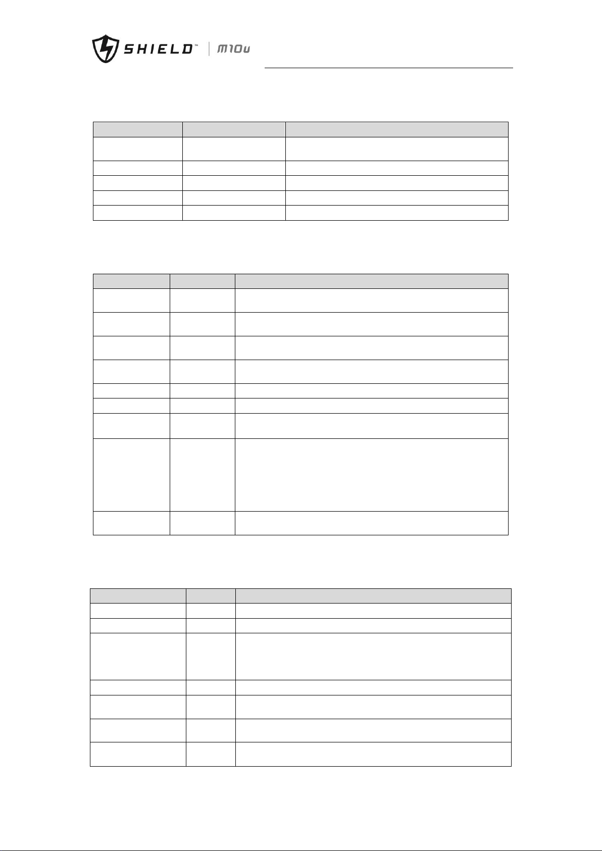
Chapter 9 Product Specification
Shield M10U user manual 57
9.4 Electrical Characteristics (Input Rectifier)
Table.9- 4: Rectifier AC Input (mains)
Items
Unit
Parameter
Rated AC Input Voltage
Vac
380/400/415(three-phase and sharing neutral with the
bypass input)
Input voltage range
Vac
-40%~+25%
Frequency
1
Hz
50/60(range: 40Hz~70Hz)
Power factor
kW/kVA, full load
0.99
THD
THDI%
4
9.5 Electrical Characteristics (Intermediate DC Link)
Table.9- 5: Battery Information
Items
Unit
Parameters
Battery bus
voltage
Vdc
Nominal: ±240V, one-side range: 198V~288V
Quantity of leadacid cells
Nominal
480V=40*6cell(12V)
Float charge
voltage
V/cell (VRLA)
2.25V/cell(selectable from 2.2V/cell~2.35V/cell)
Constant current and constant voltage charge mode
Temperature
compensation
mV/°C /cl
-3.0(selectable from : 0~-5.0, 25°C or 30°C, or inhibit)
Ripple voltage
%V float
≤1
Ripple current
%C10
≤5
Boost charge
voltage
V/cell (VRLA)
2.4V/cell(selectable from : 2.30V/cell~2.45V/cell)
Constant current and constant voltage charge mode
End of
discharging
voltage
V/cell (VRLA)
1.65V/cell(selectable from : 1.60V/cell ~1.750V/cell) @0.6C discharge
current
1.75V/cell (selectable from : 1.65V/cell~1.8V/cell) @0.15C discharge
current
(EOD voltage changes linearly within the set range according to
discharge current)
Battery Charging
Power
kW
10%* UPS capacity (selectable from : 1~20%* UPS capacity)
9.6 Electrical Characteristics (Inverter Output)
Table.9- 6: Inverter Output (to Critical Load)
Rated capacity (kVA)
Unit
10~90
Rated AC voltage
1
Vac
380/400/415(three-phase four-wire and sharing neutral with the bypass)
Freqency
2
Hz
50/60
overload
%
110% load, 1 hour
125% load, 10min
150% load, 1min
>150% load, 200ms
Fault current
%
300% short current limitation for 200ms
Non linear load
Capability
3
%
100%
Neutral current
capability
%
170%
Steady state voltage
stability
%
±1(balanced load)
±1.5(100% unbalance load)
Page 67
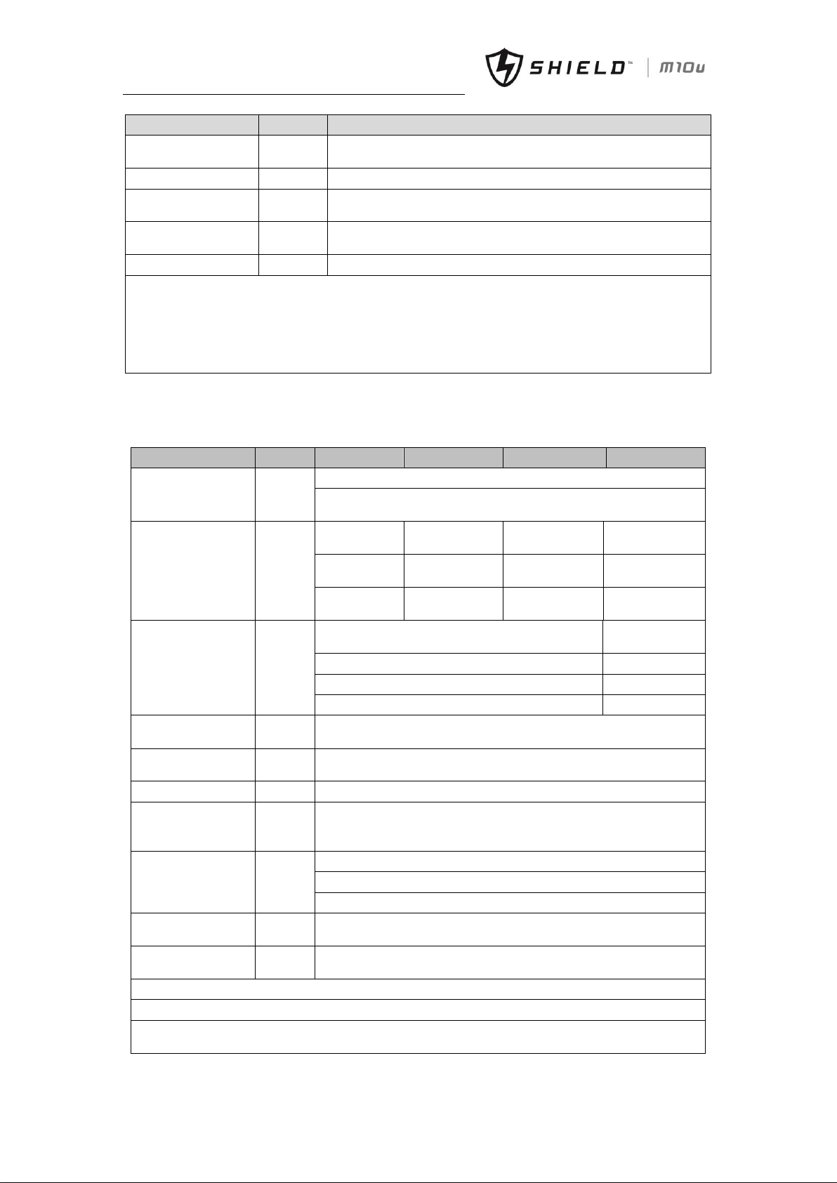
Chapter 9 Product Specification
58 Shield M10U user manual
Rated capacity (kVA)
Unit
10~90
Transient voltage
response
4
%
±5
THD % <1(linear load) , <5.5(non linear load3)
Synchronization
Window
-
Rated frequency ±2Hz(selectable: ±1~±5Hz)
Max change rate of
synch frequency
Hz/s
1: selectable: 0.1~5
Inverter voltage range
%V(ac)
±5
Note:
1. Factory setting is 380V. Commissioning engineers can set to 400V or 415V.
2. Factory setting is 50Hz. Commissioning engineers can set to 60Hz.
3. EN50091-3(1.4.58) crest ratio is 3: 1.
4. IEC62040-3/EN50091-3 including 0%~100%~0% load transient, the recovery time is half circle to within 5%
of stable output voltage.
9.7 Electrical Characteristics (Bypass Input)
Table.9- 7: Bypass Input
Rated capacity(kVA)
Unit
20
40
60
30/45/90
Rated AC Voltage
Vac
380/400/415
three-phase four-wire, sharing neutral with the rectifier input and
providing neutral reference for the output
Rated current
A
30@ 380V
60.6@380V
90@380V
45/68/135@380
V
29@400V
58@400V
87@400V
43/65/130@400
V
28@415V
55.5@415V
84@415V
42/63/126@415
V
Overload
%
<125%, long term
<110%, long
term
<130%, 10mins
<130%, 5 mins
<150%, 1min
<150%, 1min
>150%, 300ms
>150%, 300ms
Superior protection
bypass line
N/A
Thermal-magnetic breaker, the capacity is 125% of rated current output.
IEC60947-2 curve C
Current rating of
neutral cable
A
1.7×In
Frequency
Hz
50/60
Switch time
(between bypass and
inverter)
ms
Synchronized switch: ≤1ms
Bypass voltage
tolerance
% Vac
Upper limit: +10,+15,+20, +25, default: +15
Lower limit: -10, -20, -30 or -40, default:-20
(acceptable stable bypass voltage delay: 10s)
Bypass frequency
tolerance
%
±2.5, ±5, ±10 or ±20, default: ±10
SynchronizationWindow
Hz
Rated frequency±2Hz (selectable from ±0.5Hz~±5Hz)
Note:
1. Factory setting is 400V. Commissioning engineers can set to 380V or 415V.
2. Commissioning engineers can set to 50Hz or 60Hz. For example, UPS is set to frequency inverter mode,
and then bypass status will be neglected.
Page 68

Chapter 9 Product Specification
Shield M10U user manual 59
9.8 Efficiency
Table.9- 8: Efficiency, Air Exchange
Rated Efficiency (kVA)
Unit
10~90kVA
Efficiency
Normal mode(dual conversion)
%
95max
ECO mode
%
99
Battery discharging efficiency (DC/AC) (battery at nominal voltage 480Vdc and full-rated linear load)
Battery mode
%
94.5
Maximum air exchange
m3 /min
4.5/power module, 3.02/bypass module
Page 69
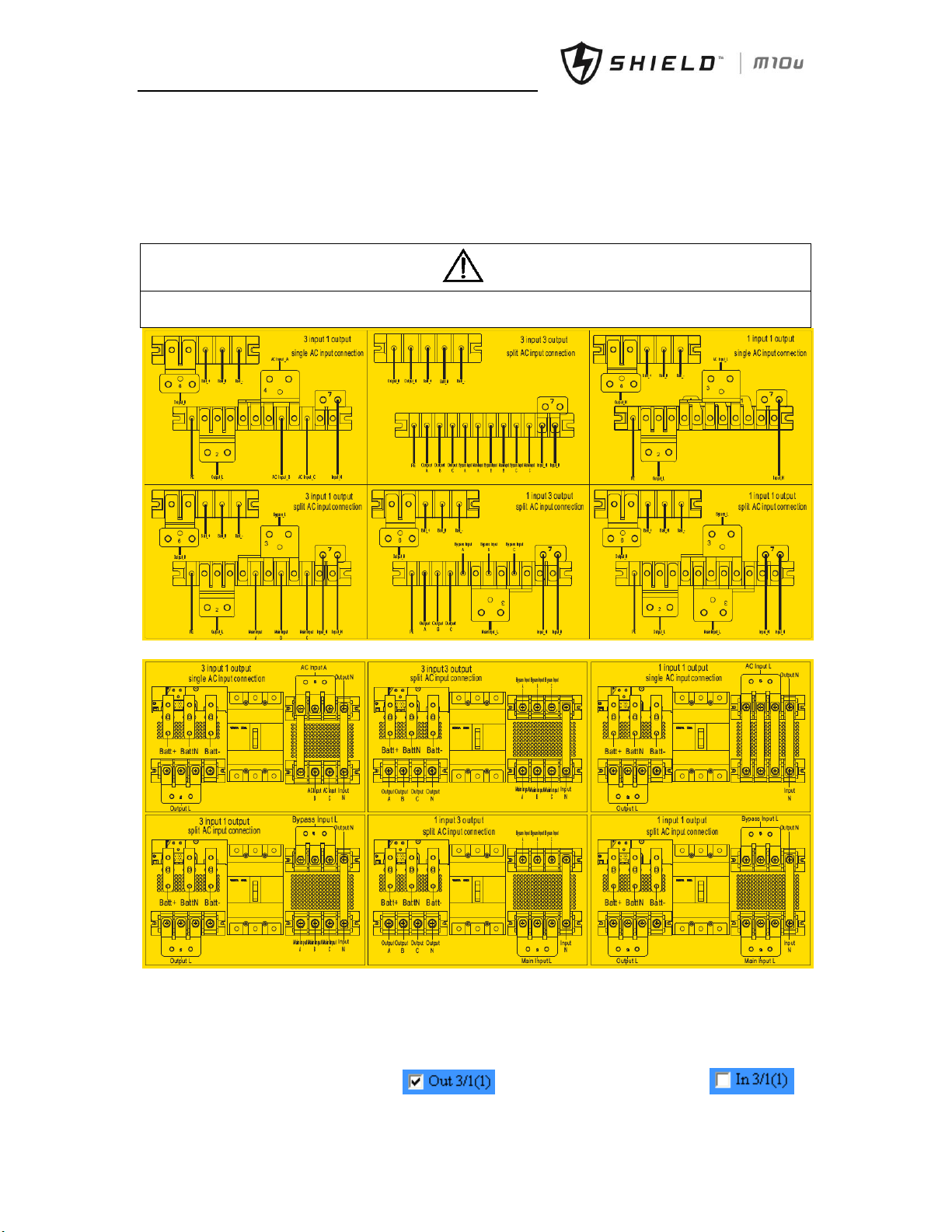
Appendix B Power Connection of Modular System
60 Shield M10U user manual
Appendix A. Power Connection of Modular System
Fig.B-1 and Fig.B-2 illustrate the power connection of modular UPS in what are known as the 3/3, 3/1, 1/3 and 1/1
configuration.
Note
If split-bypass input is needed, please disconnect the linked copper bars (phase A, B,C)
If 3/1, 1/1, 1/3 power connection are needed, optional copper kits are required. Set UPS as 3/1, 1/3 or 1/1 with software.
Fig.B- 1: Power Connection of 2 slots and 4 slots
Fig.B- 2: Power Cables Connection of 6 slots cabinet
➢ 3 phases in, 3 phases out (common input) is default setting. If need 3 phases in, 3 phases out (split bypass input),
remove connecting copper bars between bypass and main input as Fig.B-1 and Fig.B-2.
➢ If need to set UPS as 3 phases in, 1 phase out, connect cables as Fig.B-1 and Fig.B-2 as needed. Then set UPS with
software as below:
Enter in “RateSetting”, set output as in Syscode Setting1, set input as in
Syscode Setting 2, then confirm the set.
警告
危险
Page 70
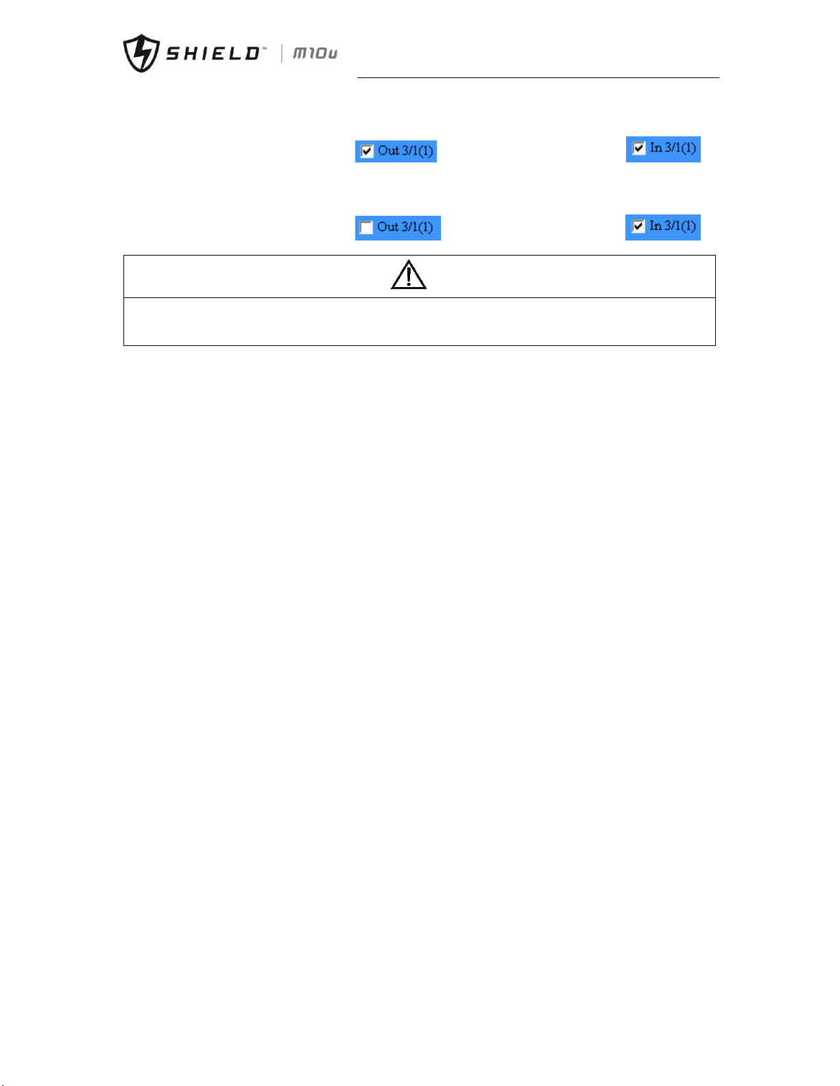
Appendix A Power Connection of Modular System
Shield M10U user manual 61
➢ If need to set UPS as 1 phase in, 1 phase out, connect cables as Fig.B-1 and Fig.B-2 as needed. Then set UPS with
software as below:
Enter in “RateSetting”, set output as in Syscode Setting1, set input as in
Syscode Setting2, then confirm the set.
➢ If need to set UPS as 1 phase in, 3 phases out (split bypass input), connect cables as Fig.B-1 and Fig.B-2 as needed.
Then set UPS with software as below:
Enter in “RateSetting”, set output as in Syscode Setting1, set input as in
Syscode Setting 2, then confirm the set.
Note
If want to set 6 slots cabinet as 1/1, 3/1, please make sure that connect output neutral cable to the input or bypass
neutral connector.
If want to set UPS as 1 phase in, 3 phases out but single input, must forbid bypass function via software.
警告
危险
Page 71

Appendix B Power Connection of Modular System
62 Shield M10U user manual
Page 72

Appendix A Power Connection of Modular System
Shield M10U user manual 63
© 2017 Shield. Shield logo is a trademarked property of their respective owners. All Rights Reserved Publication No. UM3PB01.
Specifications are subject to change without notice. While every precaution has been taken to ensure accuracy and
completeness herein, Shield assumes no responsibility, and disclaims all liability, for damages resulting from use of this
information or for any errors or omissions.
 Loading...