

Page 1

1
Page 2

2
BEFORE USING THE SHERMAN FILTERBANK, READ THE FOLLOWING
SAFETY INSTRUCTIONS
USE ONLY THE ORIGINAL ADAPTOR (OUTPUT 15V AC, 500mA) SUPPLIED WITH THIS MACHINE.
ALWAYS GRASP ONLY THE ADAPTOR WHEN PLUGGING INTO, OR UNPLUGGING FROM, AN OUTLET OR THIS UNIT.
TRY TO PREVENT CORDS AND CABLES FROM BECOMING ENTANGLED.
ALSO, ALL CORDS AND CABLES SHOULD BE PLACED SO THAT THEY ARE OUT OF THE REACH OF CHILDREN AND ANIMALS.
NEVER CLIMB ON TOP OF, NOR PLACE HEAVY OBJECTS ON THE UNIT.
NEVER HANDLE THE ADAPTOR OR ITS PLUGS WITH WET HANDS WHEN PLUGGING INTO, OR UNPLUGGING FROM, AN OUTLET OR THIS UNIT.
BEFORE MOVING THE UNIT, DISCONNECT THE ADAPTOR FROM THE OUTLET, AND PULL OUT ALL CORDS FROM EXTERNAL DEVICES.
BEFORE CLEANING THE UNIT, TURN OFF THE POWER AND UNPLUG THE ADAPTOR FROM THE OUTLET.
WHENEVER YOU SUSPECT THE POSSIBILITY OF LIGHTNING IN YOUR AREA, PULL THE PLUG ON THE ADAPTOR OUT OF THE OUTLET.
BEFORE USING THIS UNIT, MAKE SURE TO READ THE INSTRUCTIONS, AND THE USER’S MANUAL.
DO NOT OPEN OR PERFORM ANY INTERNAL MODIFICATIONS ON THE UNIT. (THE ONLY EXCEPTION WOULD BE WHERE THIS MANUAL
PROVIDES SPECIFIC INSTRUCTIONS WHICH SHOULD BE FOLLOWED IN ORDER TO MAKE INTERNAL ADJUSTMENTS.)
WHEN USING THE UNIT WITH A RACK OR STAND, THE RACK OR STAND MUST BE CAREFULLY PLACED SO IT IS LEVEL AND SURE TO REMAIN
STABLE. IF NOT USING A RACK OR STAND, YOU STILL NEED TO MAKE SURE THAT ANY LOCATION YOU CHOOSE FOR PLACING THE UNIT
PROVIDES A LEVEL SURFACE THAT WILL PROPERLY SUPPORT THE UNIT, AND KEEP IT FROM WOBBLING.
AVOID DAMAGING THE ADAPTOR CORD. DO NOT BEND IT EXCESSIVELY, STEP ON IT, PLACE HEAVY OBJECTS ON IT, ECT. A DAMAGED CORD
CAN EASILY BECOME A SHOCK OR FIRE HAZARD. NEVER USE AN ADAPTOR AFTER IT HAS BEEN DAMAGED, REPLACE IT.
WITH SMALL CHILDREN : AN ADULT SHOULD PROVIDE SUPERVISION UNTIL THE CHILD IS CAPABLE OF FOLLOWING ALL THE RULES
ESSENTIAL FOR THE SAFE OPERATION OF THE UNIT.
PROTECT THE UNIT FROM STRONG IMPACT. (DO NOT DROP IT!)
DO NOT FORCE THE UNIT’S ADAPTOR TO SHARE AN OUTLET WITH AN UNREASONABLE NUMBER OF OTHER DEVICES. BE ESPECIALLY
CAREFUL WHEN USING EXTENSION CORDS - THE TOTAL POWER USED BY ALL DEVICES YOU HAVE CONNECTED TO THE EXTENSION CORD’S
OUTLET MUST NEVER EXCEED THE POWER RATING (WATTS / AMPERES) FOR THE EXTENSION CORD. EXCESSIVE LOADS CAN CAUSE THE
INSULATION ON THE CORD TO HEAT UP AND EVENTUALLY MELT THROUGH.
BEFORE USING THE UNIT IN A FOREIGN COUNTRY, CONSULT WITH YOUR DEALER, OR QUALIFIED SHERMAN PERSONNEL.
Page 3

3
BEFORE YOU START
- MAKE SURE THE ADAPTER VOLTAGE COMPLIES WITH THE VOLTAGE OF YOUR AC POWER SUPPLY.
- AVOID EXCESSIVE FORCE ON THE JACK CONNECTIONS OR KNOBS.
- BE CAREFUL WITH YOUR SPEAKERS AT HIGH VOLUMES;
THE FILTERBANK CAN PRODUCE EXTREMELY LOW FREQUENCIES.
- READ THE SAFETY INSTRUCTIONS.
FCC WARNING
This equipment generates, uses and can radiate radio frequency energy, and if not installed and used in accordance with the instructions
manual, may cause interference to radio communications. It has been tested and found to comply with the limits for Class A computing device
persuant to Subpart J of Part 15 FCC Rules, (according to EN 55103-1 standard ) which are designed to provide reasonable protection against
such interference when operated in a commercial environment. Operation of this equipment in a residential area is likely to cause interference,
in which case the user at his own expence will be required to take whatever measures may be required to correct the interference.
Page 4

4
INTRODUCTION
This is a crash course for all you musicians who hate wasting time reading manuals. However, it's a good idea to understand the actual function
of a certain knob in order to produce a sound that you have total control over. It is easier than it looks, don't worry. The sherman filterbank (FB
from now on) is a musical instrument you need to practice with if you want to release its full potential. Soon you will find the FB an excellent
and reliable live instrument.
The 11 lessons in this booklet must be performed one by one, only skipping to the next one if you feel fully familiarized with it. But in fact,
lesson 1 to 8 is all you need to start working.
As a beginner it's better to skip the b parts. Note there is no power-on switch. The FB consumes less power than an average answering
machine, and most music set-ups & studios have a general power switch.
WHAT IS THE FILTERBANK
AND WHAT CAN YOU USE IT FOR?
It is a versitale filter effect box with tube sound overdrive, 12 parameters of it are MIDI controllable.
Any sound source, live or in studio can be used, but it’s obvious that you won’t get far without an external sound source.
It's a smart decision to buy this thing, because it is not based on processor calculation speed, it will keep it's value for many years.
APPLICATIONS INCLUDE :
- Live performance of music & dj's.
- Expansion module for modular synthesizer systems.
- Mix effect or specialised equalisation in studio.
- Enhancement of dull sounding digital gear.
- Guitar overdrive effect box...
ALL SOUND SOURCES ARE USABLE ON THE INPUT, E.G.:
Synth / Sampler / Guitar / Bass Guitar / Microphone / CD Player / Any headphone output
Drummachine / Effect Send / Rhodes Piano / Hammond Organ / Saxophone.....
Page 5

5
0 START ........................................................ 6
1 BASICS - EXPLORING FILTER 1 .............. 8
2 SYNC MODE - FILTER 2 .......................... 12
3 OUT 1 - COMBINING THE TWO FILTERS 14
4 LFO - LOW FREQUENCY OSCILLATOR ...... 20
5 AR - VOLUME MODULATION GENERATOR 22
6 ADSR - ENVELOPE FOLLOWER ................ 24
TABLE OF CONTENTS
7 FM - FREQUENCY MODULATION 36
8 AM - AMPLITUDE MODULATION 38
9 EXTERNAL INPUTS ................... 40
10 MIDI ........................................ 42
11 LINKING MORE FILTERBANKS 50
- HISTORY & PHILOSOPHY .......... 52
- MEMORY NOTATION SHEET ...... 55
TipFB Caution
Repeat
Idea Trick
Important
Page 6
6
START
ABOUT THE KNOB COLOURS...
COLOUR RELATES TO
blue Filter frequency
yellow ADSR generator
green Volume
orange Resonance/Power
white Balance
red Anti-phase correction
ABOUT THESE LESSONS...
Make yourself comfortable with this manual in front of you, your
setup and the FB powered on. Set all knobs as indicated on the
front panel drawings whenever it is required in a lesson. Feed a
signal source to the input, e.g. a synth or a sampler. Connect the
main output to your sound system. Notice the knob in the right top
corner called BYP <> EFF, it sets the balance between the
incoming signal and the processed signal. Using this knob you can
always compare the original signal with the processed signal. Turn
it completely clockwise during the lessons.
If no sound appears, check your input signal source, jack
cables, make sure the trigger indicating lights are working, set the
attack on the AR generator to zero and adjust the frequencies.
Didn't you send a MIDI volume message ? It can mute the outputs.
0
Page 7
7
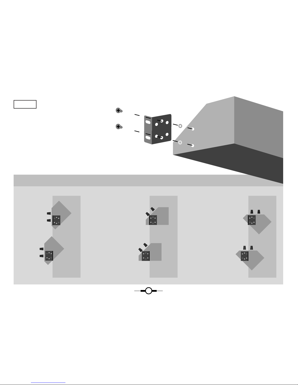
RACK MOUNTING
The 2 rack mount hooks can be screwed
on the sides of the unit as shown in fig.1.
Leave some space above the unit
in order to reach the connections on the back.
Fit the plastic nuts as shown above.
Vertical front
[ 19 Inch Rack ] [ 19 Inch Rack ] [ 19 Inch Rack ]
45¡ front
Horizontal front
figure 1
THE 6 DIFFERENT WAYS TO MOUNT YOUR FB
Page 8
8
LESSON #1
BASICS EXPLORING FILTER 1
Send a continuous signal from the signal source (e.g. a sawtooth
wave or a similar sound containing enough high harmonics) to the
input jack. Connect only the main output to your sound system.
Don't turn your sound system up to its maximum volume yet.
Turn up the input level just high enough to make both trigger
indicating lights react to the signal source. When a continuous tone
enters the FB, these lights must light up continuously too (fig.2).
Now look at fig. 3 and set the marked knobs to the indicated
positions. Start getting familiar with the following knobs :
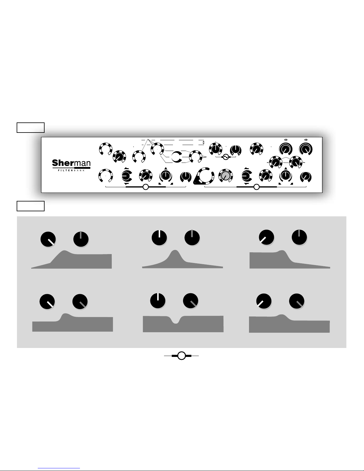
1) Frequency
2) Resonance
3) Low pass / Band pass / High pass (fig.4)
4) The correction knob :
- Band pass / 0 / - Band pass +Low pass & High pass (fig.4)
The idea behind this knob was to overcome the limitations of the
Lp/Bp/Hp balance knob. You may ask yourself : why not three
knobs, one for Lp, one for Bp and one for Hp? Simple: suppose you
turn the Lp/Bp/Hp balance knob quickly from left to right and
back. Now imagine trying to achieve the same effect with three
separate knobs...
Beginners can leave this correction knob in the 0 (mid) position.
now set Lp/Bp/Hp on Bp (mid) position. Try to minimize the filter 1
output by turning the correction knob to the left. This way you can
turn down the filter output to almost zero, because a simple
calculation learns that Bp - Bp = 0 !
When you turn the knob to -Bp+HpLp, the same as above happens
with the Bp; it is turned to zero, but now Lp+Hp are present,
making a so called NOTCH filter. Changing the frequency provides
a kind of phasing effect. This notch filter can be used for
suppressing a very small part of the frequency range, e.g. an ugly
harmonic in a snare drum, or even hum.
1
Page 9
9
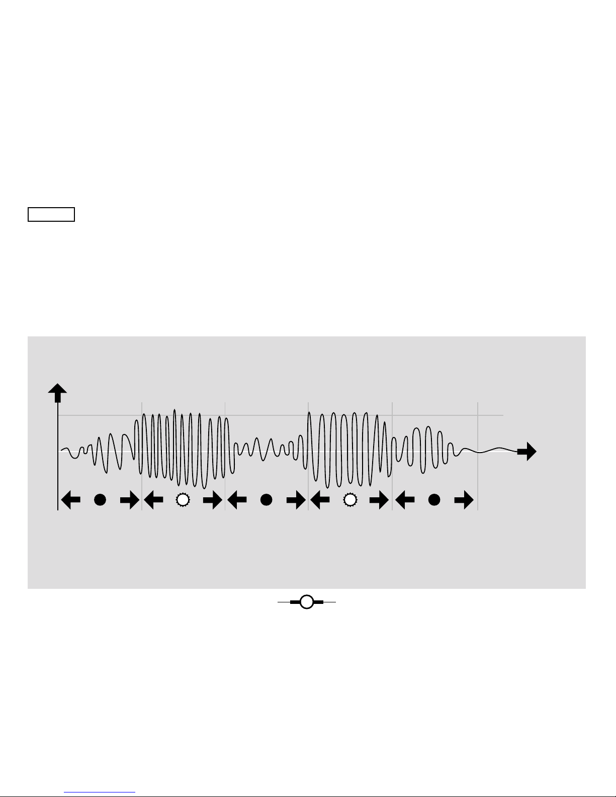
Trigger level
Amplitude of trigger (*) input signal
(*) When no jack is plugged in the trigger input, the input signal is used as trigger signal. See figure 24.
Time
Trigger Indicator light
On OnOff OffOff
figure 2
HOW
AUDIO
TRIGGERING
WORKS
Page 10

10
Suppose you want all frequencies to pass (Lp + Bp + Hp): set the
Lp Bp Hp balance on Bp and the correction knob halfway
-Bp+LpHp. This gives following calculation :
Bp + 0.5(-Bp+Lp+Hp)
= Bp - 0.5Bp + 0.5Lp + 0.5Hp
= 0.5Bp + 0.5Lp + 0.5 Hp
= 0.5(Bp + Lp + Hp)
You can make up for the weaker output with more input.
Fiddle around with these knobs
until you know what to expect from them !
By turning the input level up, the sound will start to distort, with
more harmonics being added at the input stage. Always remember
that too much input can push away the resonance peaks, giving you
the impression that the resonance knobs don't work properly. Try it
out, it's one of the features you should be very familiar with; on the
thin line between producing an over-the-top distorted racket and a
noisy sound with low dynamics, the FB works best. It's up to you to
find the right equilibrium.
Keep in mind that you always can adjust the balance between the
processed signal and the original signal, or compare them with the
Bypass-Effect knob.
In some frequency settings, a weak high “eee” sound can occur.
This is perfectly normal and typical for the Filterbank.
Don’t worry, it’s not broken. It’s mainly audible as as crossing over
between both filters. When the harmonics switch is not in the
“free” position, the “eee” sound in filter “1”, caused by freq of
filter “2” can be avoided by increasing the frequency of filter “2” a
bit, as this filter “2” setting is not significant anyway.
If you want to work in this sub bass range, the "eeee" can be easily
suppressed by turning down the hi eq on you mixing console.
LOWEST FREQUENCY RANGE
Our motto “Dangerous frequency range” is not a joke. Speaker
coils can actually burn when they move too slow, and have lack of
ventilation. This can happen at high volume and unhearable low
frequency. The FB can easily produce frequencies below 1 Hz. The
bottom frequency can change in different environment
temperatures. This is a disadvantage of this analog system, the
price to be payed for an extreme range. By inside adjustment, this
bottom frequency can be changed. To do this, you must open the
Filterbank and look for the trim holes marked “F1” an “F2”. With
a tiny screwdriver, you can re-adjust the bottom frequency of each
filter to your needs. Please don’t touch any other trim holes !
Page 11
11
1
3
5
7
9
8
6
4
2
10
1
1
1
1
4
2
6
8
9
7
5
3
SYNC
FREE
16
1
1
3
5
7
9
8
6
4
2
10
1
3
5
7
9
8
6
4
2
10
1
3
5
7
9
8
6
4
2
10
1
3
5
7
9
8
6
4
2
10
1
3
5
7
9
8
6
4
2
10
1
3
5
7
9
8
6
4
2
10
1
3
5
7
9
8
6
4
2
10
1
3
5
7
9
8
6
4
2
10
1
3
5
7
9
8
6
4
2
10
1
3
5
7
9
8
6
4
2
10
1
3
5
7
9
8
6
4
2
10
INPUT
OFF OVER
NORMAL
FREQUENCYFREQUENCY
RESO
RESO
HARMONICS
FREE
+
-
+
-
-B -B+LH
L
H
0
S R
SENS. RA
R
FM A
A
SPEED DEPTH AM PAR
SERTRIG
TRIG D
BYP EFF
2
1
+
-
B
-B -B+LH
L
H
B
1
3
5
7
9
8
6
4
2
10
HP
HIGH PASS CURVE
BAND PASS CURVE
LOW PASS CURVE
HP -B+LH
BP -B+LH
LP -B+LH
BP
LP
HP -B+LH
-B+LH
BP
LP
-B+LH
figure 3
figure 4
Page 12
12
LESSON #2
SYNC MODE - FILTER 2
Turn down the output of filter 1 (bp-bp). Set the PAR <>
SER knob to par. Set the harmonics rotary switch to
"free". Try out the settings of filter 2 ; it behaves in a
similar way as filter 1. Now set the harmonics rotary
switch to "1". The blue light will light up, indicating that
filter 2 is in sync with filter 1. This means that the full
frequency control of filter 2 is taken over by filter 1. In
“sync” mode the frequency and ADSR amount knob of
filter 2 have no function at all, and it's best to set them at
minimum. (fig.5)
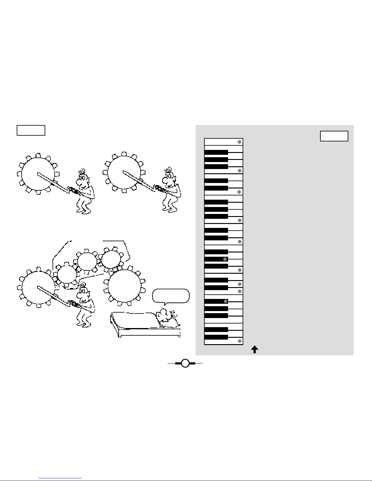
LEARNING HARMONICS:
Set reso filter 2 to maximum, select Bp and tune filter 2
(via the filter 1 frequency knob) so that a high tone
resonance can be heard. Now check the lower harmonics
by turning the rotary switch to the right. In order to get a
better idea of these harmonics, mix filter 1 on too
(correction knob at middle position, bp) with its resonance
setting to maximum as well.
Check the harmonics once again and get familiar with the
typical sound of the different harmonic intervals while
sweeping with the freq 1 knob.
HARMONIC: FREQ 2= MUSICAL: DESCRIPTION:
free freq 2 free independent freq control
1 freq 1 c equal tuning
1.5 f1 / 1.5 f - 1 1 quint down
2 f1 / 2 c - 1 1 octave down
3 f1 / 3 f- 2 2 quints down
4 f1 / 4 c - 2 2 octaves down
5 f1 / 5 g# - 3 minor
6 f1 / 6 f - 3 3 quints down
7 f1 / 7 d - 3 2 semitones above 3 octaves down
8 f1 / 8 c - 3 3 octaves down
9 f1 / 9 a# - 4 2 semitones under 3 octaves down
16 f1 / 16 c - 4 4 octaves down
see fig.6 for comparison with keyboard keys.
2
Page 13
13
1 = equal tune
1.5 = 1 quint down
2 = 1 octave down
3 = 2 quints down
4 = 2 octaves down
5 = minor
6 = 3 quints down
7 = 2 semitones above 3 octaves down
8 = 3 octaves down
9 = 2 semitones under 3 octaves down
16 = 4 octaves down
Freq filter 1 =
th
harmonic of freq filter 2
FREQ 1
FREQ 2
FREQ 1
FREQ 2
GEAR BOX
When the harmonic switch is in the “free” position,
the two filters work independently.
WHAT IS SYNC...
When the harmonic switch is in “SYNC”, filter 1 controls filter 2 via
the gear box, where you can choose 11 gears.
figure 5
figure 6
ZZZZZE BLUE ZZZLED
ZZZLIGHTS ON...
Page 14

14
LESSON #3
OUT 1 COMBINING
THE TWO FILTERS
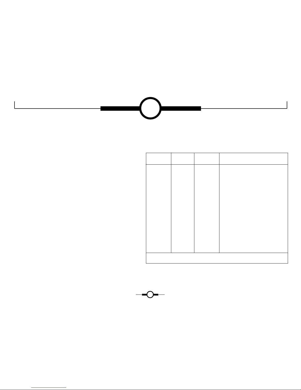
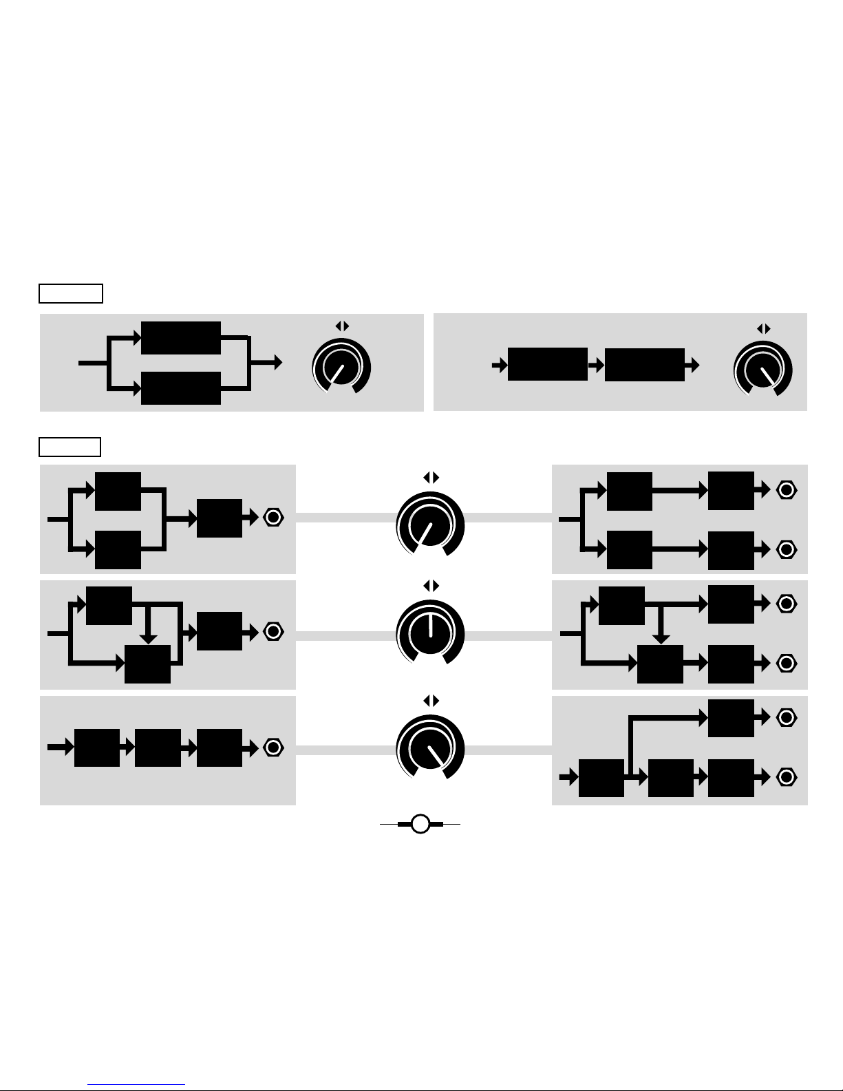
The difference between serial and parallel:
There are two fundamental ways to route the signal through the
filters (fig.7):
PARALLEL:
Turn the PAR <> SER knob completely anti-clockwise. The input
signal is fed directly to filter 1 and filter 2. The output of the two
filters is mixed and fed through the main out vca. If you connect a
jack to the out 1 however, the output of filter 1 will disappear from
the main output. In this case, the main out vca only has filter 2 as
input. The output of filter 1 always goes to out 1. This means that
you can separate the output of the two filters completely. Check this
out by connecting out 1 to your sound system as well and by
panning OUT 1 and MAIN OUT vca in stereo.(fig.8) Now set the
harmonics switch to "free" and toy around with the two filter
frequencies. Try different resonance amounts as well as different
harmonic switch settings.
SERIAL:
Turn the PAR <> SER knob completely clockwise. Disconnect the
jack from out 1. The input signal goes to filter 1 only. The output
signal of filter 1 goes to filter 2. Filter 2 goes to the MAIN OUT
vca. Obviously, if one of the filters doesn't pass the signal on,
nothing will appear at the main out. If filter 1 and filter 2 are tuned
equally (this is very easily done by setting filter 2 to sync mode "1")
the filter effect is stronger. Two 12 db filters in series provide a 24
db filter (fig.9). Get familiar with the combination of the outputs of
both filters in serial mode. Start by using identical settings, e.g.
Lp 1 + Lp 2
Bp 1 + Bp 2
Lp 1 + Bp 1 + Lp 2 + Bp 2
Hp 1 + Hp 2
and so on... (fig.9)
Check these settings also with different reso positions. Now repeat
these combinations with sync mode 1.5 (quint down). Try different
reso settings and check the difference with parallel mode. No doubt
you will find combinations giving poor results in serial mode, like
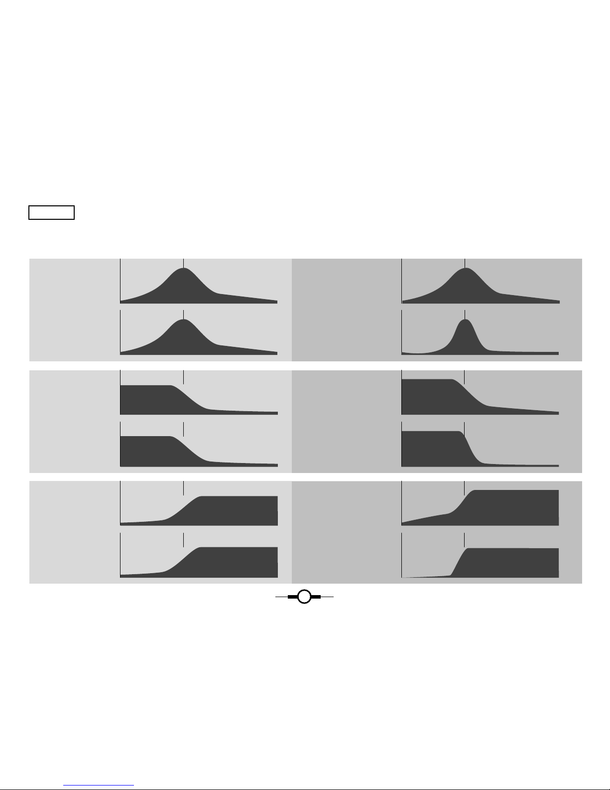
Lp1 + Hp2. see figs 10, 11 and 12. There are so many filter curve
possibilities that it's impossible to list them all, but what you should
understand is why e.g. Hp 1 + Lp 2 in sync and in serial mode
theoretically let no sound through: Because in sync freq 1 >= freq
2. This lesson never finishes, you can only get more experienced.
3
Page 15
15
OUT 1
MAIN
OUT
VCA
VCA
OUT 1
MAIN
OUT
VCA
VCA
MAIN
OUT
MAIN
OUT
MAIN
OUT
PAR SER
SERIAL
OUT
PARALLEL
WHEN A JACK IS PLUGGED IN OUT 1WHEN USING ONLY MAIN JACK
PAR SER
PAR SER
PAR SER
PAR SER
IN
OUT
IN
FILTER 1
FILTER 1
FILTER 2
FILTER 2
F 1
F 2
VCA
OUT 1
MAIN
OUT
F 1
F 2
VCA
VCA
F 1
F 2
VCA
F 1
F 2
F 1
F 2
VCA
F 1
F 2
figure 7
figure 8
Page 16
16
FILTER 1 BP
FILTER 2 BP
PARALLEL = 12db
SERIAL = 24db
FILTER CURVE, WHEN FREQ 1 = FREQ 2 MAIN OUT CURVE
FILTER 1 HP
FILTER 2 HP
PARALLEL = 12db
SERIAL = 24db
FILTER 2 HP
SERIAL = 24db
FILTER 1 HP PARALLEL = 12db
figure 9
Page 17
17
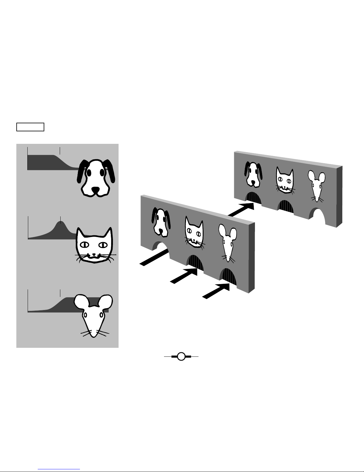
FILTER 1
LOW PASS
LOW PASS:
Only lets tones
below the
center frequency pass
BAND PASS:
Only lets tones
around the band of
center frequency pass
HIGH PASS:
Only lets tones
above the center
frequency pass
FILTER 2
HIGH PASS
figure 10
IT'S IMPORTANT TO UNDERSTAND THIS!
This is an example of a situation where no signal will come out:
in SERIAL, when the PAR<>SER knob is turned completely to SER (see figure 7),
and when freq 2 is equal or higher than freq 1.
Page 18

18
FILTER 1 LOW PASS
FILTER 2 HIGH PASS
RESULT
figure 11
In PARALLEL, the signal of both filters is simply added. In the situation shown
below, you create a small drop in the frequency range. It will become deeper and
wider the more you make freq. 2
higher than freq. 1.
Modulating such a drop, e.g.
with the LFO amount knob to the
right, will give a PHASING-like
effect.
Page 19

19
FILTER 1 LOW PASS
FILTER 2 HIGH PASS
FILTER 1 LOW PASS
FILTER 2 HIGH PASS
HIGHER
LOWER
figure 12
THIS COMES NEARER TO REALITY!
Due to overlap of the 2 filters, if freq. 1 equals
freq. 2, in fact you create a weak band-pass filter.
It grows stronger and wider the more you shift
freq. 2 lower and/or freq. 1 higher.
Page 20

20
LESSON #4
LFO LOW FREQUENCY
OSCILLATOR
Feed a stable signal to the FB, e.g. organ, strings... Keep in mind
that the trigger lights indicate when the FB is active. Connect out
1 and main out to your sound system, pan them in stereo and set
the PAR <> SER knob to parallel. Set the harmonics switch to
"free" and filter 1 and filter 2 to high reso, around the same
frequency. Now turn the LFO amount knob from zero to the right.
Both filters should react equally to the LFO.
Notice the two colour indications of the LFO. This helps to locate
the progression of very slow frequency waves. Check different LFO
frequencies with the speed knob. From the left to the middle (click)
position you get a normal LFO frequency range. From the middle
(click) position to the right, the LFO becomes an audio range
oscillator.
Leave the LFO at a nice slow cycle frequency. Turn the LFO amount
to the left - it will produce the opposite modulation for filter 1!
(fig.13) try this with different LFO speed settings.
The LFO can be retriggered (restarted) over MIDI.
This is a new feature in models starting from serial Number 1041:
toggling from unblock audio trigger to block audio trigger restarts
the LFO.
It works a bit random, wich is an advantage, and occasionally can
retrigger with very loud input; nothing to worry about.
You do this by sending MIDI note C#4 preceeded by C4, the notes
that are also used for blocking and unblocking audio trigger of
ADSR.
4
Page 21

21
1
3
5
7
9
8
6
4
2
10
SPEED DEPTH
FREQUENCY 1
FREQUENCY 2
1
3
5
7
9
8
6
4
2
10
SPEED DEPTH
1
3
5
7
9
8
6
4
2
10
SPEED DEPTH
FREQUENCY 1
FREQUENCY 2
FREQUENCY 1
FREQUENCY 2
GREEN
RED RED
GREEN
RED RED
GREEN
RED RED
LED COLOUR
EFFECT OF THE POSITION OF THE LFO DEPTH KNOB
figure 13
HOW THE LFO DEPTH KNOB WORKS
Page 22

22
TB303 TIP
Here a way to achieve the sequencer behaviour of a Roland
tb303, with MIDI. Make your source glide as you like to hear it on
a track. Make a ghost copy track of that in your sequencer. Give a
negative delay and another MIDI channel to that ghost track. Make
e.g. a program on the main MIDI channel with the desired sound
(square, sawtooth, polyphonic, whatever). Put this in the FB's
ADSR or AR trigger input. Make a copy of that program on the
ghost's MIDI channel. Put this in the FB's main audio input.
RESULT: The notes will start gliding to the next notes before the
gate fully opens the VCA (also adjustable with pre delay, in smaller
amount than the ghost track) and thus before the quantize of the
song. A real bassplayer does similar things.
LESSON #5
AR
VOLUME
MODULATION
GENERATOR
This generator equally controls the OUT 1 and MAIN OUT VCA's.
Play a sound with a slow attack, e.g. a string sound. Make sure that
the ar trigger light goes on and off. Get familiar with the
attack/release settings (starting from minimum) and with their
influence on the output volume. You can also experiment with drum
loops.
Setting attack and release to minimum produces a rhythmic
gating effect. By doing so you might experience a slight loss of
attack (punch). This is because of the limited speed of the attack.
You can speed up the attack by sending MIDI controller 5 value 0
to the FB. The default power-up value of controller 5 is 63 (=
halfway 127). if this is not fast enough, record the AR triggers via
MIDI and play them back with a slight amount of pre-delay.
5
Page 23

23
AR Trigger
Amplitude
Time
On OnOffOff
On OnOff OffOff
1
3
5
7
9
8
6
4
2
10
1
3
5
7
9
8
6
4
2
10
RA
1
3
5
7
9
8
6
4
2
10
1
3
5
7
9
8
6
4
2
10
RA
1
3
5
7
9
8
6
4
2
10
1
3
5
7
9
8
6
4
2
10
RA
1
3
5
7
9
8
6
4
2
10
1
3
5
7
9
8
6
4
2
10
RA
figure AR
OUTPUT AMPLITUDE
IN FUNCTION OF AR KNOB POSITIONS
Page 24

24
LESSON #6
ADSR
ADSR = ATTACK DECAY SUSTAIN RELEASE
Set the toggle switch to ADSR (upward). Set harmonics to sync 1,
filter 1 and filter 2 to max reso, serial mode, as shown in fig.14.
Set the AR generator to zero attack and maximum release. Turn
the envelope modulation knob of filter 1 slightly clockwise from the
middle position. This way you have a high resonant filter that
provides a clearly audible indication of the ADSR generator output.
The bi-colour (yellow+ red-) light right next to the release knob
always gives a visual indication of the ADSR generator's activity.
Now slowly play the keyboard, or use a sequencer to have your
hands free to explore the ADSR generator. Make sure the ADSR
trigger light flashes in a slow and regular manner. Now, try out the
following exercises : figs 15 to 21
Now repeat these exercises with different (+ and - ) positions of
the modulation amount knob of filter 1 (filter 2 is still in sync).
Repeat these exercises with filter 2 "free" running in parallel mode;
experiment also with the envelope modulation amount knob of filter
2. At this point you should be familiar with the ADSR knobs.
ANOTHER EXERCISE:
Run a sixteenth note repetitive sequencer or arpeggio pattern with a
short or percussive sound. Adjust the input level to make the ADSR
trigger follow the sixteenth notes. Set the ADSR as in the last
example in fig 21. Now try adjusting the attack time so that the
ADSR indication light turns red with each sixteenth note. Slowly
increase the attack time so that the ADSR generator misses every
other trigger pulse. The ADSR now makes an eight note cycle.
Continue increasing the attack time slightly, so that it misses two
out of three trigger pulses. This produces triplets. Repeat this
exercise with e.g. a drum loop.
You can turn the ADSR generator into a second LFO by making
a jack connection from link out to the adsr trig in. Set freq 1 to
zero, the ADSR amount of filter 1 to negative and the sustain to
maximum. Using attack and release you can change the waveshape
and speed. This "weird" LFO can be modulated with the normal
LFO, MIDI pitch wheel, Unknown Control 5, and so on. The
disadvantage is that filter 1 will go too low to be usable, unless you
insert an attenuator between link out and ADSR trig.
6
Page 25

25
1
3
5
7
9
8
6
4
2
10
1
1
1
1
4
2
6
8
9
7
5
3
SYNC
FREE
16
1
1
3
5
7
9
8
6
4
2
10
1
3
5
7
9
8
6
4
2
10
1
3
5
7
9
8
6
4
2
10
1
3
5
7
9
8
6
4
2
10
1
3
5
7
9
8
6
4
2
10
1
3
5
7
9
8
6
4
2
10
1
3
5
7
9
8
6
4
2
10
1
3
5
7
9
8
6
4
2
10
1
3
5
7
9
8
6
4
2
10
1
3
5
7
9
8
6
4
2
10
1
3
5
7
9
8
6
4
2
10
INPUT
OFF OVER
NORMAL
FREQUENCYFREQUENCY
RESO
RESO
HARMONICS
FREE
+
-
+
-
-B -B+LH
L
H
0
S R
SENS. RA
R
FM A
A
SPEED DEPTH AM PAR
SERTRIG
TRIG D
BYP EFF
2
1
+
-
B
-B -B+LH
L
H
B
1
3
5
7
9
8
6
4
2
10
IS
TRANSITION
LEVEL
REACHED?
IS
TRIGGER ON?
NO
YES
NO
GO TO
ZERO
WITH
RELEASE
SPEED
This flow-chart diagram illustrates what the ADSR voltage is obliged to do.
GO TO
TRANSITION
LEVEL
WITH
ATTACK
SPEED
GO TO
SUSTAIN
LEVEL
WITH
DECAY
SPEED
IS
TRIGGER ON?
YES
NO
NO
YES YES
IS
TRIGGER ON?
figure 14
IF YOU UNDERSTAND THIS, YOU KNOW PERFECTLY WHAT TO EXPECT FROM THE ADSR!
Page 26

1
3
5
7
9
8
6
4
2
10
1
3
5
7
9
8
6
4
2
10
1
3
5
7
9
8
6
4
2
10
0
S R
SENS. RA
A
D
+
-
1
3
5
7
9
8
6
4
2
10
1
3
5
7
9
8
6
4
2
10
1
3
5
7
9
8
6
4
2
10
0
S R
SENS. RA
A
D
+
-
1
3
5
7
9
8
6
4
2
10
1
3
5
7
9
8
6
4
2
10
1
3
5
7
9
8
6
4
2
10
0
S R
SENS. RA
A
D
+
-
1
3
5
7
9
8
6
4
2
10
1
3
5
7
9
8
6
4
2
10
1
3
5
7
9
8
6
4
2
10
0
S R
SENS. RA
A
D
+
-
TRIGGER OFFENVELOPE VOLTAGE
= RED
= YELLOW
ADSR
ENVELOPE
CURVE
EXAMPLES
TIME
MAX. SUSTAIN LEVEL
TRANSITION LEVEL
26
figure 15
Play the ADSR
really very slow
and see how it works.
Page 27

1
3
5
7
9
8
6
4
2
10
1
3
5
7
9
8
6
4
2
10
1
3
5
7
9
8
6
4
2
10
0
S R
SENS. RA
A
D
+
-
1
3
5
7
9
8
6
4
2
10
1
3
5
7
9
8
6
4
2
10
1
3
5
7
9
8
6
4
2
10
0
S R
SENS. RA
A
D
+
-
1
3
5
7
9
8
6
4
2
10
1
3
5
7
9
8
6
4
2
10
1
3
5
7
9
8
6
4
2
10
0
S R
SENS. RA
A
D
+
-
1
3
5
7
9
8
6
4
2
10
1
3
5
7
9
8
6
4
2
10
1
3
5
7
9
8
6
4
2
10
0
S R
SENS. RA
A
D
+
-
TRIGGER OFFENVELOPE VOLTAGE
TIME
MAX. SUSTAIN LEVEL
TRANSITION LEVEL
27
figure 16
Page 28

1
3
5
7
9
8
6
4
2
10
1
3
5
7
9
8
6
4
2
10
1
3
5
7
9
8
6
4
2
10
0
S R
SENS. RA
A
D
+
-
1
3
5
7
9
8
6
4
2
10
1
3
5
7
9
8
6
4
2
10
1
3
5
7
9
8
6
4
2
10
0
S R
SENS. RA
A
D
+
-
1
3
5
7
9
8
6
4
2
10
1
3
5
7
9
8
6
4
2
10
1
3
5
7
9
8
6
4
2
10
0
S R
SENS. RA
A
D
+
-
1
3
5
7
9
8
6
4
2
10
1
3
5
7
9
8
6
4
2
10
1
3
5
7
9
8
6
4
2
10
0
S R
SENS. RA
A
D
+
-
TRIGGER OFFENVELOPE VOLTAGE
TIME
MAX. SUSTAIN LEVEL
TRANSITION LEVEL
28
figure 17
Page 29

1
3
5
7
9
8
6
4
2
10
1
3
5
7
9
8
6
4
2
10
1
3
5
7
9
8
6
4
2
10
0
S R
SENS. RA
A
D
+
-
1
3
5
7
9
8
6
4
2
10
1
3
5
7
9
8
6
4
2
10
1
3
5
7
9
8
6
4
2
10
0
S R
SENS. RA
A
D
+
-
1
3
5
7
9
8
6
4
2
10
1
3
5
7
9
8
6
4
2
10
1
3
5
7
9
8
6
4
2
10
0
S R
SENS. RA
A
D
+
-
1
3
5
7
9
8
6
4
2
10
1
3
5
7
9
8
6
4
2
10
1
3
5
7
9
8
6
4
2
10
0
S R
SENS. RA
A
D
+
-
TRIGGER OFFENVELOPE VOLTAGE
TIME
MAX. SUSTAIN LEVEL
TRANSITION LEVEL
29
figure 18
Page 30

1
3
5
7
9
8
6
4
2
10
1
3
5
7
9
8
6
4
2
10
1
3
5
7
9
8
6
4
2
10
0
S R
SENS. RA
A
D
+
-
1
3
5
7
9
8
6
4
2
10
1
3
5
7
9
8
6
4
2
10
1
3
5
7
9
8
6
4
2
10
0
S R
SENS. RA
A
D
+
-
1
3
5
7
9
8
6
4
2
10
1
3
5
7
9
8
6
4
2
10
1
3
5
7
9
8
6
4
2
10
0
S R
SENS. RA
A
D
+
-
1
3
5
7
9
8
6
4
2
10
1
3
5
7
9
8
6
4
2
10
1
3
5
7
9
8
6
4
2
10
0
S R
SENS. RA
A
D
+
-
TRIGGER OFFENVELOPE VOLTAGE
TIME
MAX. SUSTAIN LEVEL
TRANSITION LEVEL
Decay and sustain are changed, but won't play any role before the transition level is reached.
30
figure 19
Page 31

1
3
5
7
9
8
6
4
2
10
1
3
5
7
9
8
6
4
2
10
1
3
5
7
9
8
6
4
2
10
0
S R
SENS. RA
A
D
+
-
1
3
5
7
9
8
6
4
2
10
1
3
5
7
9
8
6
4
2
10
1
3
5
7
9
8
6
4
2
10
0
S R
SENS. RA
A
D
+
-
1
3
5
7
9
8
6
4
2
10
1
3
5
7
9
8
6
4
2
10
1
3
5
7
9
8
6
4
2
10
0
S R
SENS. RA
A
D
+
-
1
3
5
7
9
8
6
4
2
10
1
3
5
7
9
8
6
4
2
10
1
3
5
7
9
8
6
4
2
10
0
S R
SENS. RA
A
D
+
-
TRIGGER OFFENVELOPE VOLTAGE
TIME
MAX. SUSTAIN LEVEL
TRANSITION LEVEL
31
figure 20
Page 32

1
3
5
7
9
8
6
4
2
10
1
3
5
7
9
8
6
4
2
10
1
3
5
7
9
8
6
4
2
10
0
S R
SENS. RA
A
D
+
-
1
3
5
7
9
8
6
4
2
10
1
3
5
7
9
8
6
4
2
10
1
3
5
7
9
8
6
4
2
10
0
S R
SENS. RA
A
D
+
-
1
3
5
7
9
8
6
4
2
10
1
3
5
7
9
8
6
4
2
10
1
3
5
7
9
8
6
4
2
10
0
S R
SENS. RA
A
D
+
-
TRIGGER OFF
TRIGGER OFF
ENVELOPE VOLTAGE
TIME
MAX. SUSTAIN LEVEL
TRANSITION LEVEL
TRIGGER OFF
ATTACK TIME
1
3
5
7
9
8
6
4
2
10
1
3
5
7
9
8
6
4
2
10
1
3
5
7
9
8
6
4
2
10
0
S R
SENS. RA
A
D
+
-
32
figure 21
Page 33

33
ATTACK KNOB POSITION
30 SECONDS
0 SECONDS
0 10987654321
5 SECONDS
10 SECONDS
15 SECONDS
20 SECONDS
25 SECONDS
figure 22
ABOUT
THE SPEED
OF THE ADSR
I had some discussion with a Filterbank user about the average low speed
of the ADSR, which makes it difficult to adjust fast ADSR curves.
This is true for fast percussive effects, and I must admit that in the
design period, slow ambient flows were fashionable.
However there is an instant solution : the ADSR speed can get up to 4
times faster. How ? Transmit MIDI control messages to the Filterbank
that affect the Attack, Decay and Release speed. When the Filterbank is
powered up, the ADSR speeds are initialised 1/4 of their maximal speed
= control value 63. This is half of an exponential scale ( see Fig. 27). So
if this is your problem, just change that initial value to 0.
Attack time in function of knob position, when midi controller 5
(porta time) value is 63 (=default value). Not valid for envelope
follower.
Page 34

34
ENVELOPE
FOLLOWER
A SENS. R = ATTACK SENSITIVITY RELEASE
An envelope follower basically creates an output voltage that
follows the level of its input signal. (fig.23) Set the toggle switch to
its downwards position. Now the ADSR generator becomes an
envelope follower. Set attack and release to zero. Plug in a dynamic
sound source, like a (bass) guitar, piano, organ with swell pedal,
drum loop or any other device providing volume variations. Adjust
sens in combination with the envelope modulation amount knobs of
the filters, for good response. Watch the ADSR indication light, it
should flash yellow when the envelope follower is active, weak red
when there's no input signal. Try the envelope follower with
different modulation amounts of filter 1 (filter 2 in sync). Repeat
these exercises with filter 2 free running in parallel mode;
experiment also with the envelope modulation amount knob of filter 2.
NOTE : The trigger input of the ADSR here becomes the envelope
follower input. You can plug in another signal source in this input,
and use its volume variations for filter modulation. Try it !
NOTE : Decay has no function in the envelope follower, and attack
and release of the ADSR generator are not MIDI-controllable in
envelope follower mode.
No MIDI control of envelope modulation amount possible ?
Simply connect ADSR out to FM in and MIDI foot control will do
the job. Even negative : send MIDI foot control half way (value 63)
and anticipate that with the envelope amount knob(s) until no
modulation is heard. Sending MIDI foot control above and under
63 will result in positive and negative modulation.
Page 35

35
Input signal
A Sens. R output voltage
Envelope follower output with SHORT ATTACK time and SHORT RELEASE time
Envelope follower output with LONG ATTACK time and SHORT RELEASE time
Envelope follower output with SHORT ATTACK time and LONG RELEASE time
Time
1
3
5
7
9
8
6
4
2
10
1
3
5
7
9
8
6
4
2
10
1
3
5
7
9
8
6
4
2
10
0
S R
SENS. RA
A
D
+
-
1
3
5
7
9
8
6
4
2
10
1
3
5
7
9
8
6
4
2
10
1
3
5
7
9
8
6
4
2
10
0
S R
SENS. RA
A
D
+
-
1
3
5
7
9
8
6
4
2
10
1
3
5
7
9
8
6
4
2
10
1
3
5
7
9
8
6
4
2
10
0
S R
SENS. RA
A
D
+
-
figure 23
HOW THE ENVELOPE FOLLOWER WORKS
Page 36

36
LESSON #7
FM
FREQUENCY
MODULATION
FM equally modulates the frequencies of both filters. Set the knobs
as shown in fig.14 but without ADSR modulation. Send a low
monophonic tone to the FB. Increase the FM amount firmly and
then turn it down slightly. Work with different sound sources like
bass, organ, sawtooth and square wave. Check FM with different
freq 1 settings and input levels. The reso settings also play an
important role here. Now insert a jack cable in the FM input. You
will notice that FM doesn't work internally anymore. Now you can
try a different sound source with this input,
e.g. take another synth or sampler output and experiment with
this source playing the same melody as the processed melody, but
now try different tuning intervals between input and FM source.
NOTE: The FM input also accepts DC voltages from e.g. a cv/gate
output, a modular system's lfo or ADSR, the voltage output of any
analog sequencer, any pedal or device that provides a variable
voltage or signal output.
You can use the FM amount knob as a common ADSR amount
knob for both filters by connecting ADSR out to FM in.
You can produce subharmonic FM as follows: Connect MAIN
OUT to FM in. Route only OUT 1 to your sound system. Set both
RESO controls to maximum. First try parallel mode, afterwards
serial. Now try out different harmonics (also "free") with different
FM amounts.
7
Page 37

Original resonating filter wave
Time
Resulting resonating filter wave
Time
Frequency modulation signal or control voltage at FM input
Time
37
figure FM
THE PRINCIPLE OF FREQUENCY MODULATION
Page 38

38
LESSON #8
AM
AMPLITUDE MODULATION
AM equally modulates both OUT 1 and MAIN OUT VCA's. AM
modulation is the key to warm, fat and extremely aggressive
sounds. Set the knobs as shown in fig.14 but without ADSR
modulation. Send a monophonic sound to the input. Increase the
AM amount firmly and then turn it down slightly. Work now with
different pitches, sounds and input levels.
Because this modulation is working on the VCA's, the AM signal
is multiplied with the processed signal. Just as in maths,
multiplication can make big numbers out of small ones, so mind
your speakers.
NOTE: when there is no jack plugged in the am input, the output of
filter 2 is used as an am source, so reso 2 will have more influence
than reso 1.
Now insert a jack cable in the AM input. You will notice that AM
doesn't work internally anymore. Now you can try a different sound
source with this input, e.g. take another synth or sampler
output and experiment with this source playing the same melody as
the processed melody, but now try different tuning intervals
between the input and AM source.
You can use the ADSR envelope generator in addition to the AR
generator for controlling output dynamics; simply connect the
ADSR output to the am input. Also this way, in envelope follower
mode, you create an expander. An expander is the opposite of a
compressor.
IMPORTANT : internal am needs enough input signal & high reso
setting of filter 2 to have significant effect. once familiar with the
kind of effect, you can use it in a more subtle way.
8
Page 39

Original resonating filter wave
Time
Resulting resonating filter wave
Time
Amplitude modulation signal or control voltage at AM input
Time
39
figure AM
THE PRINCIPLE OF AMPLITUDE MODULATION
Page 40

40
LESSON #9
EXTERNAL
INPUTS
Take a look at fig.24 for an overview of the internal routings.
repeat lesson 5, 6, 7 and 8 with a second signal source connected to
the relevant input. make sure this signal is strong enough to make
the triggers work (lesson 5 & 6), or to hear sufficient modulation
(lesson 7 & 8). For the triggers (lesson 5 & 6) a drum machine
should do the job. For AM and FM, any line level signal e.g. a
synth, sampler or headphone output is ok, a microphone to weak.
If you want the triggers to work very fast, use very short input
pulses or sound bursts. Note that the trigger inputs also work with
gate signals from e.g. a cv/gate output.
You can make a jack connection from the ADSR out to the AR
trigger in. When the ADSR has a slow attack , the AR trigger will
be delayed. The amount of this delay depends on the attack time.
For the FM & AM inputs an organ or bass signal is excellent.
Note that these inputs also work with dc signals, e.g. an external
LFO, ADSR, CV...
Don't be afraid to try different external connections, the inputs can
cope with a lot. You may also short cirquit two outputs of 1 or more
filterbanks, if you want e.g. mix two filterbanks, or ADSR out with
the audio OUT 1 to AM in...
However, this doesn't mean that YOU can, so don't even think
about making any kind of direct connection with dangerous voltage
sources like tube amps, tv sets, ac mains, power plants, toasters,
lightning rods or ufo's...
9
Page 41

PLUGGING A JACK
AUTOMATICALLY
DISCONNECTS
THE NORMAL
INTERNAL ROUTING
TRIGGER AR
OUTPUT FILTER 2
TRIGGER ADSR
AMFM
INPUT
41
figure 24
INTERNAL ROUTING OF THE JACKS
Page 42

42
(*) The modulation wheel is also used for a special function : in
sync mode, when set to 127, it pitches the whole machine exactly
one octave up! Try this out with high reso settings, this octave
switching can be musically very interesting. It makes the FB
operate in ultra high frequency ranges, so mind your tweeters.
Leave the modulation wheel on 0, if you don't use it, values between
0 and 127 can cause strange things in sync mode.
(**) Unknown control 5 = porta speed.
See also figs. 27, 28 and 29 for the influence of MIDI on the attack
speed of ADSR. A similar effect applies to decay and release
timings.
LESSON #10
MIDI
The basic power-on channel is always 16. You can change the
receive channel by sending a program change (any number) on the
actual channel (16 on power-up). The channel on which the first
following MIDI message (any type) is sent becomes the new receive
channel. The MIDI out channel always remains 16. If you have two
or more FB's in the same MIDI chain and you want to assign
different receive channels to them, proceed as follows : power on
the first FB in the MIDI chain. Change its receive channel. Power
on the next FB in the chain. Change its receive channel, and so
on...
MIDI IN
First, get familiar with the controllers :
MIDI MESSAGE FILTER BANK FUNCTION POWER-UP
VALUES
Pitch wheel (fig.25) Cutoff freq filter 1 (fine resolution) 4096 (zero)
Channel pressure
(fig.26) Resonance filter 1 0
Modulation wheel(*) Cutoff freq filter 2 0
Breath control Resonance filter 2 0
Foot control FM depth 0
Main volume VCA bias 127
Expression AM/ring depth 0
Unknown Control 5(**) Attack time ADSR 63
U.C. 16 Decay time ADSR 63
U.C. 17 Release time ADSR 63
U.C. 18 Attack time AR 63
U.C. 19 Release time AR 63
10
Page 43

43
WHAT HAPPENS
WHEN MIDI CONTROLS
COME IN
FREQ 1 KNOB MOVED BY HAND FROM 1 TO 10
TIME
INCOMING MIDI PITCH WHEEL
ACTUAL FREQUENCY FILTER 1,
ASSUMING NO LFO, ADSR NOR FM MODULATION
E.G. Filter 1 Frequency:
Freq. 1 knob position
MIDI Pitch wheel
ADSR modulation
LFO modulation
FM input
actual
cutoff
frequency
filter 1
+ =
figure 25
Page 44

44
RESO 1 KNOB MOVED BY HAND FROM 1 TO 10
TIME
INCOMING MIDI CHANNEL PRESSURE
ACTUAL RESONANCE FILTER 1
E.G. Resonance filter 1 :
Reso 1 knob position
MIDI channel pressure
As you can see on the graphics, resonance can go to
maximum using MIDI, while the reso 1 knob stays on minimum
Attack time in function of
MIDI controller 5 (porta time) value
when attack knob in position 3.
actual
resonance
filter 1
+ =
MIDI CONTROLLER VALUE
12 SECONDS
0 SECONDS
1279563310
2 SECONDS
4 SECONDS
6 SECONDS
8 SECONDS
10 SECONDS
figure 26 figure 27
Page 45

45
ADSR output curve,
attack zone
MIDI controller 5, constantly on 63 (default)
ADSR output curve
MIDI controller 5
figure 28
This is an example
of how the attack time
of the ADSR
can be speeded up
and slowed down
while it’s running.
You can do similar on-the-fly
time changes with the decay,
release and attack release
of the AR generator too.
In these examples MIDI
controller 5 is drawn in a
sequence program.
Page 46

46
3D VIEW OF THE RELATION
TIME - KNOB SETTING - MIDI CONTROL
Knob positionMidi controller
Actual time
figure 29
Page 47

47
Try now to make a melody with pitch wheel. Set the knobs as in the figure shown below. Set freq 1 to an acceptable
start note for the desired melody. Now draw or give in (e.g. in cubase grid edit) zero (middle) pitch wheel
modulation on the start time. Now draw the second note, on a later time, and let one bar loop to hear the pitch
variation. Now adjust pitch of the second "note" e.g. in grid edit, changing value 1 and 2. A MIDI pitch wheel
message consists of two 7 bit bytes, one for coarse and one for fine tune. Only when the second note is in tune, you
may build further your melody. Leave the freq 1 knob in its original position, it changes the tuning intervals.
Tip for producers: once you have “tuned” the filters this way, bring down the resonances and filter instruments
in your mix to make them resonate along with the music in a subtle way! It gets even more interesting in parallel,
with different harmonic switch settings.
1
3
5
7
9
8
6
4
2
10
1
1
1
1
4
2
6
8
9
7
5
3
SYNC
FREE
16
1
1
3
5
7
9
8
6
4
2
10
1
3
5
7
9
8
6
4
2
10
1
3
5
7
9
8
6
4
2
10
1
3
5
7
9
8
6
4
2
10
1
3
5
7
9
8
6
4
2
10
1
3
5
7
9
8
6
4
2
10
1
3
5
7
9
8
6
4
2
10
1
3
5
7
9
8
6
4
2
10
1
3
5
7
9
8
6
4
2
10
1
3
5
7
9
8
6
4
2
10
1
3
5
7
9
8
6
4
2
10
INPUT
OFF OVER
NORMAL
FREQUENCYFREQUENCY
RESO
RESO
HARMONICS
FREE
+
-
+
-
-B -B+LH
L
H
0
S R
SENS. RA
R
FM A
A
SPEED DEPTH AM PAR
SERTRIG
TRIG D
BYP EFF
2
1
+
-
B
-B -B+LH
L
H
B
1
3
5
7
9
8
6
4
2
10
Page 48

48
MIDI TRIGGER NOTES
Plug in the MIDI out of a keyboard to the MIDI in
of the FB, set the transmit channel of the keyboard
to 16, and play the triggers from the keyboard.
figure 30
Forced gate off AR, speeded up release
Normal trigger AR
Trigger AR, speeded up attack
Normal trigger both
Forced gate off ADSR, speeded up release
Normal trigger ADSR
Trigger ADSR, speeded up attack
Block audio trigger AR
Unblock audio trigger AR
Block audio trigger ADSR
Unblock audio trigger ADSR
C4
TRIGGERING
If you want triggering to happen exclusively via MIDI, you can
block the audio triggering. There are two soft toggle switches in the
FB. Their function is to block the AR and ADSR audio trigger
sensitivity (so that MIDI triggering does not interfere with
triggering by the audio signal). You can toggle these switches by
sending the following MIDI note messages:
C4 : unblock audio trigger ADSR
C#4 : block audio trigger ADSR
D4 : unblock audio trigger AR
D#4: block audio trigger AR
Power-up unblocks the audio triggers.
The actual MIDI triggering is done by sending following MIDI
notes:
F#4: normal trigger ADSR
A#4: normal trigger AR
G#4: normal trigger both
F4: trigger ADSR with speeded-up (*) attack
(MIDI attack time = zero)
G4: forced gate-off ADSR with speeded-up (*) release
A4: trigger AR with speeded-up (*) attack
B4: forced gate-off AR with speeded-up (*) release
Page 49

49
(*) The actual time is calculated by multiplying the setting of the
knob with its MIDI controller value (3d fig.29). When it says
“speeded-up”, the actual MIDI control value (=63 when powered
up) is temporarily set to zero.
E.g. if you set the attack time knob of the AR to almost zero and
send a high value via MIDI, you can program the following in your
sequencer: send note A#4 a few seconds before the start of the
beat, so that the volume of the FB reaches its maximum just on the
start, and use note A4 for quick attacks and speedy percussions in
the song. Then use note A#4 again in a break, etc.
NOTE : For very fast triggering: same story as for audio triggering:
use very short notes because, once triggered, a trigger light will
remain on for a short while.
MIDI OUT
Trigger light action is always sent to the midi out port as normal
trigger notes on channel 16, whatever the source (audio or MIDI).
This is useful for recording with a sequencer. Only F#4 and A#4
are sent out.
E.g. the audio triggering of a drum loop can be recorded via
MIDI out, and these patterns can then be used with another audio
signal by feeding back the recorded notes in the FB's MIDI in. Don't
forget to block the audio sensitivity.
Note : This is the only thing that is sent out.
MIDI THRU
The FB is equipped with 3 MIDI thru ports. They act like a normal
MIDI thru box with the MIDI in.
Note: If you experience MIDI problems, do not panic right
away. Test the unit by connecting the MIDI out of a synth directly to
the MIDI in of the FB. Check the pitch wheel response of the cutoff
frequency filter 1 and find the MIDI trigger notes. Avoid MIDI
loops and too many devices in one MIDI chain. Some may give bad
MIDI thru! Avoid too long MIDI cables.
Page 50

50
LESSON #11
LINKING
MORE
FILTERBANKS
You can chain the FB's endlessly (fig.31) with the link jacks
specially designed for this purpose. The first (master FB) in the
chain's filter 1 will act as master over the filter 1 of all the slaves.
Filter 2 of each FB will act as always : free or in sync with freq 1
(of the master in this case). Try out different harmonic switch
settings on the FB’s in the chain to form chord intervals.
Avoid using too long jack-jack cables for this.
MASTER
SHERMAN FILTERBANK
SLAVE
SHERMAN FILTERBANK
LINK out
LINK in
LINK in
LINK in
And so on...
LINK out
LINK out
SLAVE
SHERMAN FILTERBANK
SLAVE
SHERMAN FILTERBANK
figure 31
11
Page 51

51
1
3
5
7
9
8
6
4
2
10
1
1
1
1
4
2
6
8
9
7
5
3
SYNC
FREE
16
1
1
3
5
7
9
8
6
4
2
10
1
3
5
7
9
8
6
4
2
10
1
3
5
7
9
8
6
4
2
10
1
3
5
7
9
8
6
4
2
10
1
3
5
7
9
8
6
4
2
10
1
3
5
7
9
8
6
4
2
10
1
3
5
7
9
8
6
4
2
10
1
3
5
7
9
8
6
4
2
10
1
3
5
7
9
8
6
4
2
10
1
3
5
7
9
8
6
4
2
10
1
3
5
7
9
8
6
4
2
10
INPUT
OFF OVER
NORMAL
FREQUENCYFREQUENCY
RESO
RESO
HARMONICS
FREE
+
-
+
-
-B -B+LH
L
H
0
S R
SENS. RA
R
FM A
A
SPEED DEPTH AM PAR
SERTRIG
TRIG D
BYP EFF
2
1
+
-
B
-B -B+LH
L
H
B
1
3
5
7
9
8
6
4
2
10
MAKE A VERY NEAT
48db
FILTER :
Set up two FB's. Connect the MAIN OUT of the first to the input of
the second. Make a link connection and set the knobs of both FB's
as shown in fig.32. Set up a third FB, linked in serial mode and
with the same settings, and your 72 db filter is ready. You can even
make a similar stereo, triple or quadrophonic setup etc.
MASTER
SHERMAN FILTERBANK
SLAVE
SHERMAN FILTERBANK
Audio in
Audio out
Audio out
Audio in
Link out Link in
figure 32
Page 52

52
I made over a hundred dance records in the late eighties, pioneered
with the use of drumloops. All the time I built gear for myself like
a short MIDI delay to bypass the delay of my prophet 3000, tube
preamps to overdrive synth sounds, compressors & noise gates to
use on a spring reverb, a programamble bunch of guitar pedals, an
air scratcher ... at that time you couldn't buy those things at
reasonable prices. Once I made a sampler of an apple II by
swapping it's memory with an Ibanez delay. 4 years ago I decided to
use all my experience and started to design a commercial
manufacturable modular synth with mouse drawed envelope curves,
Moog filters, a complex modulation matrix and a real time mouse
drawable arpeggiator sequencer. That monster is still not ready, but
because many people asked me for, I started to make a filter box,
which i equipped with all the functions I would like as a musician,
not just another Curtis chip based box with one lowpass filter and a
reso knob. No, I wanted something much more powerful than
anything on the market, but for a reasonable price. The first model
of the Sherman was hand built, but after 40 pcs I realised that it
was too difficult to keep building that by hand. So I developed the
Filterbank like it is now : smaller with SMD (surface mount device)
components, easy to assemble by a machine, cheaper because of
less printboard space use, but more functions, MIDI controllable,
but still analog.
HISTORY & PHILOSOPY
I'm not an engineer. I play guitar for 20 years now, but fiddle with
electronics for 25 years. 18 years ago I built a modular system for
use on guitar, but I was not satisfied with the overdrive behaviour of
most transistor-based gear. I looked at Marshall amps and studied
how they achieved that warm sound, measured their curves and
frequence responses.
Page 53

53
Allthough it is small, it contains more parts than a Minimoog,
thanks to this SMD technology. Electronically seen is a discrete
resistor the same as an SMD resistor, the SMD is 10 times smaller.
Most manufacturers use DSP (digital signal processing) now,
because it's so cheap to develop. To make a filter, they just have to
write a formula in the DSP. A DSP based machine sounds too
perfect and has too low dynamics to equal analog gear in power &
liveness. It makes me sick when I see people spending their money
on DSP based gear, that keep their value until the next "software
update version", even worse : very often there come out new DSP's,
faster, cheaper, more powerful. Musicians are tired of scrolling thru
menu's, so they use factory patches, recycle the same samples
endlessly and make uninspired records. It was getting even more
ridiculous when those "vintage" sample playback modules came out,
with the sounds of famous analog synths. In fact you can make
several million sounds out of e.g. an arp 2500. If a modular system
is a world, such a vintage module is small bunch of (digitized)
photo's, taken in that world. With DSP overdrive simulation, you
can just reach the limit of your 20 bit number. So, overdrive must
be programmed, but still sounds dead.
Why ? A car crash is always different, in the same circumstances,
on the contrary, a computer simulated car crash is always the same.
Thats why real analog sounds more "live" than a bunch of routines
trying to simulate analog cirquits.
Thanks to noise, crossover distortion and influence on power
fluctuations, temperature, aging pot's, all those thing that we tried
to avoid, an analog gear has character. A 909 bassdrum is never
the same, because there is a small analog synth in the 909,
generating the bassdrum. A sampled 909 bassdrum has never the
punch of the real. Why ? D/A converters are limited in frequency
response and dynamics. Fortunately, some manufacturers, such as
Studio Electronics, Tube Tech ... go back to analog, which unfortunately- costs a lot more, because every circuit has to be
tested and adjusted. The Sherman is such gear, but I think it has a
fair price for it’s features.
Herman Gillis, designer
Special thanks to the following people for supporting me all the
way; my wonderful wife Mieke Frère, Joel Cordier, Daan Stuyven,
Luk Page, The staff & artists of R&S records, and last but not least
: all abusers.
Page 54

54
INDEX
Adapter..................................................................... 2
ADSR....................................................................... 24
AM........................................................................... 38
AR...................................................................... 22
Audio trigger.................................................................... 9
Block-unblock audio trigger..................................... 48
BYPASS<>EFFECT................................................. 6
Correction knob........................................................ 11
Envelope follower...................................................... 34
External inputs.......................................................... 40
FM............................................................................ 36
Harmonic switch...................................................... 12
History & philosphy............................................... 52
Index ......................................................... Are you serious ?
Introduction............................................................. 4
Lp-Bp-Hp .................................................................. 11
LFO........................................................................... 20
Link system.................................................. 50
Main out.................................................................. 15
MIDI.......................................................................... 42
MIDI out.................................................................... 49
MIDI resonance.......................................................... 44
MIDI panic................................................... 49
MIDI pitch wheel................................................. 43
MIDI time control..................................................... 44
MIDI trigger ..................................................... 48
No output? ................................................... 17
Notch filter .................................................................. 8
Octave switching via MIDI ............................................ 42
OUT 1 .......................................................................... 15
Overview ................................................................... 45
PARALLEL<>SERIAL................................................ 15
Patch sheets............................................................... 55
Phasing ........................................................................ 18
Rack mounting................................................................ 7
Resonating melody................................................. 47
Sync ( ZZZZe blue ZZZled )............................................. 13
Tb 303 tip....................................................................... 22
© SHERMAN PRODUCTIONS
STATIONSWIJK 73, B-3272 TESTELT, BELGIUM. - WWW.PING.BE/SHERMAN - EMAIL: SHERMAN@PING.BE
DESIGNED & DEVELOPED BY HERMAN GILLIS
VISUALS BY DAAN STUYVEN / BROOD & SPELEN
Page 55

55
MULTIPLY / COPY THIS PAGE!!!
FOR UNLIMITED USE
1
3
5
7
9
8
6
4
2
10
1
1
1
1
4
2
6
8
9
7
5
3
SYNC
FREE
16
1
1
3
5
7
9
8
6
4
2
10
1
3
5
7
9
8
6
4
2
10
1
3
5
7
9
8
6
4
2
10
1
3
5
7
9
8
6
4
2
10
1
3
5
7
9
8
6
4
2
10
1
3
5
7
9
8
6
4
2
10
1
3
5
7
9
8
6
4
2
10
1
3
5
7
9
8
6
4
2
10
1
3
5
7
9
8
6
4
2
10
1
3
5
7
9
8
6
4
2
10
1
3
5
7
9
8
6
4
2
10
INPUT
OFF OVER
NORMAL
FREQUENCYFREQUENCY
RESO
RESO
HARMONICS
FREE
+
-
+
-
-B -B+LH
L
H
0
S R
SENS. RA
R
FM A
A
SPEED DEPTH AM PAR
SERTRIG
TRIG D
BYP
EFF
2
1
+
-
B
-B -B+LH
L
H
B
1
3
5
7
9
8
6
4
2
10
1
3
5
7
9
8
6
4
2
10
1
1
1
1
4
2
6
8
9
7
5
3
SYNC
FREE
16
1
1
3
5
7
9
8
6
4
2
10
1
3
5
7
9
8
6
4
2
10
1
3
5
7
9
8
6
4
2
10
1
3
5
7
9
8
6
4
2
10
1
3
5
7
9
8
6
4
2
10
1
3
5
7
9
8
6
4
2
10
1
3
5
7
9
8
6
4
2
10
1
3
5
7
9
8
6
4
2
10
1
3
5
7
9
8
6
4
2
10
1
3
5
7
9
8
6
4
2
10
1
3
5
7
9
8
6
4
2
10
INPUT
OFF OVER
NORMAL
FREQUENCYFREQUENCY
RESO
RESO
HARMONICS
FREE
+
-
+
-
-B -B+LH
L
H
0
S R
SENS. RA
R
FM A
A
SPEED DEPTH AM PAR
SERTRIG
TRIG D
BYP
EFF
2
1
+
-
B
-B -B+LH
L
H
B
1
3
5
7
9
8
6
4
2
10
MEMORY NOTATION SHEET
SOUND NAME:.....................
SOUND NAME:.....................
SOUND NAME:.....................
Page 56

56
MULTIPLY / COPY THIS PAGE!!!
FOR UNLIMITED USE
1
3
5
7
9
8
6
4
2
10
1
1
1
1
4
2
6
8
9
7
5
3
SYNC
FREE
16
1
1
3
5
7
9
8
6
4
2
10
1
3
5
7
9
8
6
4
2
10
1
3
5
7
9
8
6
4
2
10
1
3
5
7
9
8
6
4
2
10
1
3
5
7
9
8
6
4
2
10
1
3
5
7
9
8
6
4
2
10
1
3
5
7
9
8
6
4
2
10
1
3
5
7
9
8
6
4
2
10
1
3
5
7
9
8
6
4
2
10
1
3
5
7
9
8
6
4
2
10
1
3
5
7
9
8
6
4
2
10
INPUT
OFF OVER
NORMAL
FREQUENCYFREQUENCY
RESO
RESO
HARMONICS
FREE
+
-
+
-
-B -B+LH
L
H
0
S R
SENS. RA
R
FM A
A
SPEED DEPTH AM PAR
SERTRIG
TRIG D
BYP
EFF
2
1
+
-
B
-B -B+LH
L
H
B
1
3
5
7
9
8
6
4
2
10
1
3
5
7
9
8
6
4
2
10
1
1
1
1
4
2
6
8
9
7
5
3
SYNC
FREE
16
1
1
3
5
7
9
8
6
4
2
10
1
3
5
7
9
8
6
4
2
10
1
3
5
7
9
8
6
4
2
10
1
3
5
7
9
8
6
4
2
10
1
3
5
7
9
8
6
4
2
10
1
3
5
7
9
8
6
4
2
10
1
3
5
7
9
8
6
4
2
10
1
3
5
7
9
8
6
4
2
10
1
3
5
7
9
8
6
4
2
10
1
3
5
7
9
8
6
4
2
10
1
3
5
7
9
8
6
4
2
10
INPUT
OFF OVER
NORMAL
FREQUENCYFREQUENCY
RESO
RESO
HARMONICS
FREE
+
-
+
-
-B -B+LH
L
H
0
S R
SENS. RA
R
FM A
A
SPEED DEPTH AM PAR
SERTRIG
TRIG D
BYP
EFF
2
1
+
-
B
-B -B+LH
L
H
B
1
3
5
7
9
8
6
4
2
10
1
3
5
7
9
8
6
4
2
10
1
1
1
1
4
2
6
8
9
7
5
3
SYNC
FREE
16
1
1
3
5
7
9
8
6
4
2
10
1
3
5
7
9
8
6
4
2
10
1
3
5
7
9
8
6
4
2
10
1
3
5
7
9
8
6
4
2
10
1
3
5
7
9
8
6
4
2
10
1
3
5
7
9
8
6
4
2
10
1
3
5
7
9
8
6
4
2
10
1
3
5
7
9
8
6
4
2
10
1
3
5
7
9
8
6
4
2
10
1
3
5
7
9
8
6
4
2
10
1
3
5
7
9
8
6
4
2
10
INPUT
OFF OVER
NORMAL
FREQUENCYFREQUENCY
RESO
RESO
HARMONICS
FREE
+
-
+
-
-B -B+LH
L
H
0
S R
SENS. RA
R
FM A
A
SPEED DEPTH AM PAR
SERTRIG
TRIG D
BYP
EFF
2
1
+
-
B
-B -B+LH
L
H
B
1
3
5
7
9
8
6
4
2
10
MEMORY NOTATION SHEET
SOUND NAME:.....................
SOUND NAME:.....................
SOUND NAME:.....................
 Loading...