

SHERCO 250 SE/R, 300 SE/R Workshop Manual

WORKSHOP MANUAL
250 SE/R
300 SE/R

2
250-300 SE-R

ENGLISH
CONTENTS
FOREWORD ................................................................4
ENGINE TOOL LIST .....................................................5
250 SE-R and 300 SE-R ....................................................5
TECHNICAL SPECIFICATIONS .....................................6
Engine ...............................................................................6
Carburettor ........................................................................7
Cycle part ..........................................................................7
FACTORY SETTINGS ...................................................8
Fork ..................................................................................8
Shock absorber .................................................................9
OPERATIONS REQUIRING REMOVAL OF THE ENGINE OR
NOT ...........................................................................9
ENGINE REMOVAL/ASSEMBLY .................................10
Removing the engine .......................................................10
Reassembling the engine in the frame ..............................11
DISMANTLING THE ENGINE ......................................12
Draining the gearbox ........................................................12
Removing the pinion and selector .....................................12
Removing the cylinder head, cylinder and piston ................13
Removing the clutch housing ............................................14
Removing the pressure plate and discs .............................15
Removing the electric starter ............................................16
Removing the primary transmission ..................................16
Removing the locking mechanism .....................................17
Removing the ignition housing ..........................................18
Removing the torque limiter and the starter drive...............18
Removing the ignition .......................................................19
Intake pipe and valve box .................................................19
Separating the half crankcases .........................................20
Removing the gear selection.............................................20
Removing the connecting rod assembly ............................21
CHECKING ENGINE COMPONENTS ............................22
Connecting rod assembly .................................................22
Balance weights, checking the external dimensions ...........22
Radial play of the connecting rod head .............................22
Lateral play of the connecting rod head ............................23
Checking the crankshaft's run out ....................................23
Piston..............................................................................23
Gap spacing ....................................................................24
Piston pin check ..............................................................24
Checking the wear condition of the cylinder ......................24
Standard cylinder replacement .........................................24
Disassembling the exhaust valve system ...........................25
Functional check ..............................................................26
Valve stop learning after cylinder reassembly ....................30
Valve box, intake pipe sleeve ............................................30
Clutch .............................................................................31
Connecting rod assembly .................................................31
REASSEMBLING THE ENGINE ...................................32
Gearbox ..........................................................................32
Assembling the half crankcases........................................33
Gear selection mechanism ...............................................34
Primary transmission and clutch .......................................35
Clutch discs, pressure plate..............................................36
Clutch housing .................................................................37
Piston and cylinder ..........................................................38
Cylinder head ..................................................................39
Valve box and intake pipe .................................................40
Gearbox output pinion ......................................................40
Mounting the ignition and its cover ...................................41
Mounting the electric starter .............................................41
DIAGNOSTIC TOOL ...................................................42
Presentation of the ignition management system and exhaust
valve opening management system ..................................42
Description of Exxodiag diagnostic tool reference 4967 .....43
Composition of the diagnostic tool ....................................43
Installing the diagnostic tool .............................................43
Connection with Keyless system .......................................47
Software setup : setup menu ............................................48
Update and synchronisation menu ....................................49
Using the software ...........................................................51
TIGHTENING TORQUES TABLE ..................................61
CARBURETTOR ADJUSTMENT TABLE .......................62
SE-R 250 carburettor adjustment table .............................62
CARBURETTOR ADJUSTMENT TABLE .......................63
SE-R 300 carburettor adjustment table .............................63
CHECKING THE LOAD CIRCUIT..................................64
Static control values (engine off) 250 SE-R/300 SE-R ........64
Dynamic control values ....................................................64
T° SENSOR, ENGINE RPM SENSOR, HV COIL CHECK . 65
Main harness...................................................................66
Standard lights harness ....................................................67
Racing lights harness .......................................................68
Accessories harness ........................................................69
3

This manual is primarily intended for qualified mechanics working in a properly
equipped workshop.
A solid knowledge of mechanics and the specific SHERCO tools for the 250
SE-R and 300 SE-R engines are required to perform the various operations.
This workshop manual complements the SHERCO 250 SE-R and 300 SE-R user
manual.
FOREWORD
4
250-300 SE-R

ENGLISH
ENGINE TOOL LIST
250 SE-R and 300 SE-R
Tool reference Designation
5749 Clutch block
4753 Ignition block
2067 Swing-arm pin tool
R467 Right crankcase primary shaft bearing tool
R465 Secondary shaft bearing tool
5397 Gearbox output shaft bearing tool
R446 Gearbox output spi tool
5398 Barrel selection bearing tool
5399 Left crankcase crankshaft bearing tool
R469 Right crankcase crankshaft bearing tool
5400 Clutch side crankshaft spi tool
5401 Ignition side crankshaft spi tool
5402 HK0808 needle cage tool
(water pump, starter drive double pinion,
starter drive)
1968 Water pump spi seal tool
1821 Engine support
5206 Primary pinion block tool
2073 Spring block (pin selection)
R462 Magnetic flywheel puller
R464 Crankshaft ring extractor
R453 Selector axis bearing assembly tool
R444 Selector spi seal tool
6267 Diagnostic Key less tool
4967 Diagnostic briefcase
5

TECHNICAL SPECIFICATIONS
Type
Single cylinder 2 stroke liquid cooling
Capacity 249.32 CC
293.14 CC
Bore/Stroke 66.4/72 mm
72/72 mm
Petrol
Unleaded with an octane rating of at least 98
mixed with 2-stroke oil (2 %)
Cooling
Liquid with forced circulation
Ignition system
Synerject electronic ignition
Spark plug
NGK BR7ES/DENSO W22ESRU
Distance between spark plug
electrodes
0.7 mm
Piston Cast aluminium
Engine oil 750 ml SAE 10W40
Primary transmission 27 : 75
Gearbox :
1st
2nd
3rd
4th
5th
66 speeds
14 : 32
15 : 26
19 : 27
21 : 24
23 : 22
25 : 21
Final transmission 14 X 49
Clutch Oil bathed multi disks, hydraulic control
Starter Electric starter
Battery 12V 4Ah
Alternator 220W
ENGINE
6
250-300 SE-R

ENGLISH
250 300
Carburettor type
KEIHIN PWK 36S AG KEIHIN PWK 36S AG
Needle position 3rd position from the top
3rd position from the top
Jet needle
N1EG (N84K) N8RE (N84K)
Main jet KEA 165 (KEA 115) KEA 172 (KEA 115)
Idle jet KEP 42 (KEA38) KEP 42 (KEA 38)
Choke jet 85 (50) 85 (50)
Air regulating screw
opening
1T 1/4 1T 1/2
Valve spacing N°5.5 N°7
CARBURETTOR
Rahmen
Halbperimetrisch aus CrMo-Stahl mit hinterem
Bügel aus Aluminium
Fork
(Racing) WP suspension USD Ø48 mm
(Factory) WP suspension Xplor
Rear suspension
WP suspension with separate cylinder, aluminium
swing arm
Front/rear stroke 300/330 mm
Front brake Ø 260 mm disc
Rear brake Ø 220 mm disc
Disc brakes Wear limit : 2.7 mm front and 3.6 mm rear
Front tyre 90/90-21’’
Rear tyre 140/80-18’’
Off-road pressure front/rear 0.9 bar
Fuel tank capacity 10.4 l including 1 litre reserve
Steering column angle 27.3°
Wheelbase 1480 mm
Weight 105 kg
Gewicht 105 kg
CYCLE PART
7
FACTORY SETTINGS - WP FORK USD SUSPENSION Ø48 MM
Compression
Comfort 20 clicks back
Standard 13 clicks back
Sport
8 clicks back
Expansion
Comfort 18 clicks back
Standard 13 clicks back
Sport 10 clicks back
Pre-tension
Comfort 4 turns
Standard
6 turns
Sport 8 turns
Spring stiffness
Driver weight : 65-75 kg 4.0N/mm
Driver weight : 75-85 kg 4.2N/mm (factory)
Driver weight : 85-95 kg 4.4N/mm
Oil type SAE 4
Measured oil level
(compressed and spring-less
fork) from the top of the
upper tube
110 mm
FACTORY SETTINGS
FORK
FACTORY SETTINGS - WP FORK XPLOR SUSPENSION
Compression
Comfort 18 clicks back
Standard 15 clicks back
Sport
12 clicks back
Expansion
Comfort 18 clicks back
Standard 15 clicks back
Sport 12 clicks back
Pre-tension
Comfort + 0
Standard
+ 0
Sport + 6
Spring stiffness
Driver weight : 65-75 kg 4.2 N/mm
Driver weight : 75-85 kg 4.4 N/mm (factory)
Driver weight : 85-95 kg 4.6 N/mm
Oil type SAE 4
Quantity of oil 606 ml
Oil level height from the top
of the tube
100 mm (Min. 90 – Max. 120 mm)
Spring length with pretension spacer
474 mm
8
250-300 SE-R

ENGLISH
FACTORY SETTINGS - WP SUSPENSION SHOCK ABSORBER
Low speed compression
Comfort 20 clicks back
Standard 15 clicks back
Sport 12 clicks back
High speed compression
Comfort 2.5 turns back
Standard 2 turns back
Sport 1.5 turns back
Expansion
Comfort 15 clicks back
Standard 13 clicks back
Sport 11 clicks back
Spring stiffness
Driver weight : 65-75 kg 48N/mm
Driver weight : 75-85 kg 51N/mm (factory)
Driver weight : 85-95 kg
54N/mm
SHOCK ABSORBER
OPERATIONS REQUIRING REMOVAL
OF THE ENGINE OR NOT
Operation requiring removal
of the engine
Operation not requiring the
removal of the engine
Crankshaft (including
connecting rod kit)
•
Complete gearbox •
Crankshaft bearing •
Gearbox bearing •
Piston •
Cylinder •
Cylinder head •
Ignition •
Starter pinions •
Complete clutch •
Water pump •
Gear selection assembly •
9

ENGINE REMOVAL/ASSEMBLY
REMOVING THE ENGINE
• Drain (see user manual).
• Engine oil.
• Coolant.
• Remove the seat.
• Disconnect the battery.
• Remove the tank with its inlets.
• Disconnect the complete wiring harness connected to the engine (starter
terminal, interference suppressor, actuator).
• Remove the exhaust (see user manual).
• Remove the carburettor.
• Remove the secondary transmission chain (quick coupler).
• Remove the chain guard.
• Remove the clutch slave cylinder.
WARNING
To remove the engine, you must remove the swing arm's pivot bolt to detach the rear wheel/swing
arm assembly. Secure the chassis with a jack to prevent the motorcycle from overturning.
• Remove the water hoses connected to the engine.
• Remove the left radiator.
• Loosen all the engine screws.
• Loosen the swing-arm pin.
• Remove the cylinder head-frame lugs and its electric motor.
• Remove the engine pins.
• Remove the swing-arm pin.
• Disconnect the valve cables from the pulley.
• Remove the engine.
WARNING
When the clutch slave cylinder is removed, the piston is no longer held in place. Secure the piston
with a plastic collar.
10
250-300 SE-R

ENGLISH
REASSEMBLING THE ENGINE IN THE FRAME
To reassemble, follow the disassembly procedure in reverse while respecting the tightening torques of screws and nuts :
Engine screw : 60Nm.
Swivel-arm screw : 100 Nm.
Clutch slave cylinder screw : 10 Nm.
Head-frame screw : 23 Nm.
11
DISMANTLING THE ENGINE
Refer to the 250 SE-R/300 SE-R spare parts catalogue for exploded views.
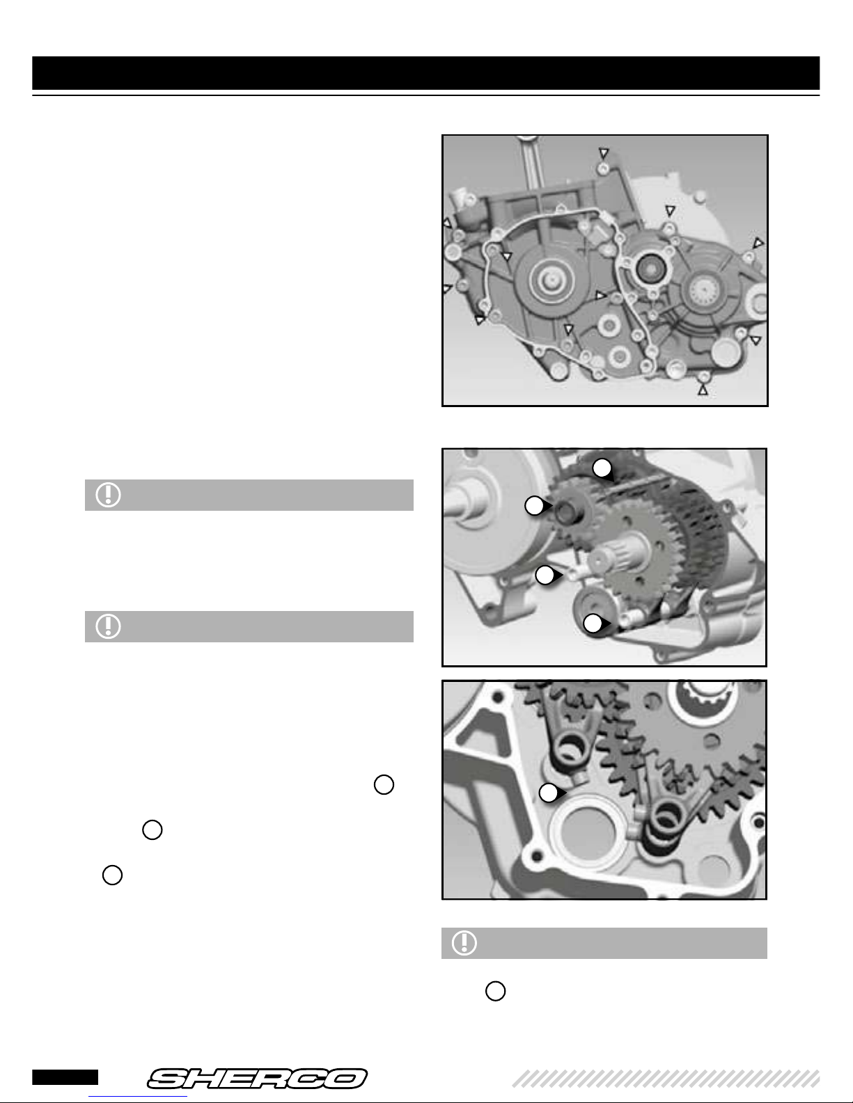
DRAINING THE GEARBOX
• Remove the drain plugs 1 and 2, let the
oil drain.
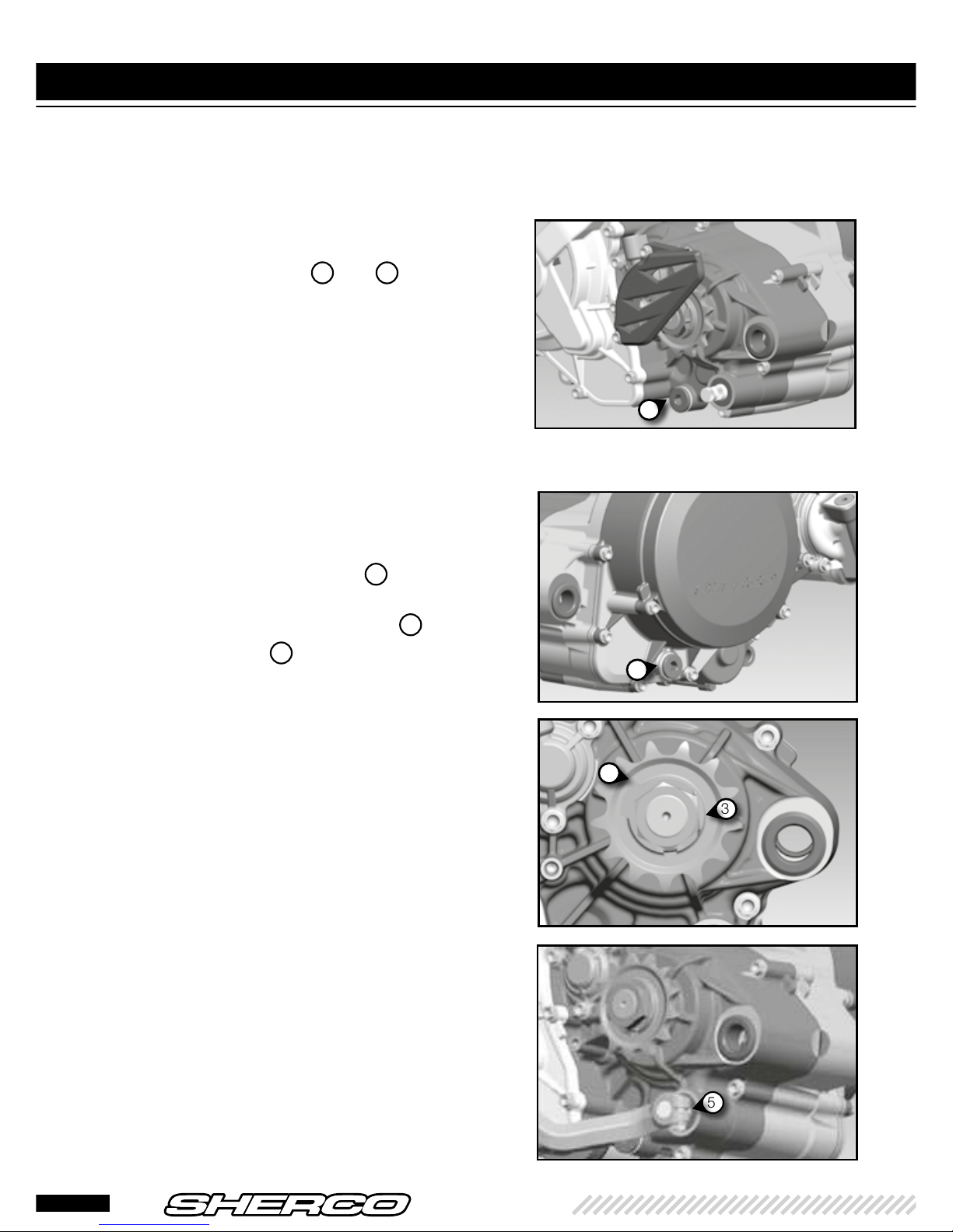
REMOVING THE PINION AND
SELECTOR
• Unfold the safety washer's tab 3 using a
punch.
• Remove the gearbox output pinion
4
.
• Remove the screw
5
and extract the
selector.
• Remove the clutch control rod.
1
2
4
3
5
12
250-300 SE-R
ENGLISH
• Remove the exhaust valve actuator 2.
• Remove the exhaust chamber cover
3
.
• Remove the 4 screws
4
on the base of
the cylinder and remove it.
• Mask the cover.
REMOVING THE CYLINDER
HEAD, CYLINDER, AND PISTON
• Remove the shoulder bolts 1, the copper
washers, remove the cylinder head and the two
o-rings.
1
2
3
4
13
DISMANTLING THE ENGINE (next)
• Remove the screws and extract the
clutch housing. Remove the gasket.
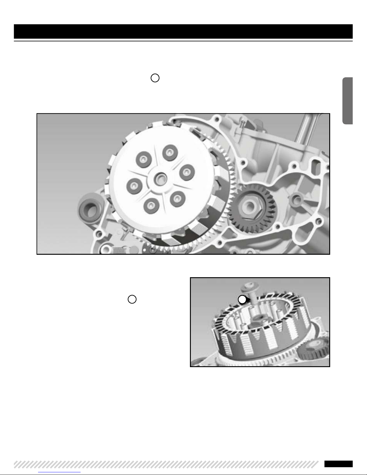
REMOVING THE CLUTCH
HOUSING
• Remove the screws and the water pump
cover. Remove the gasket.
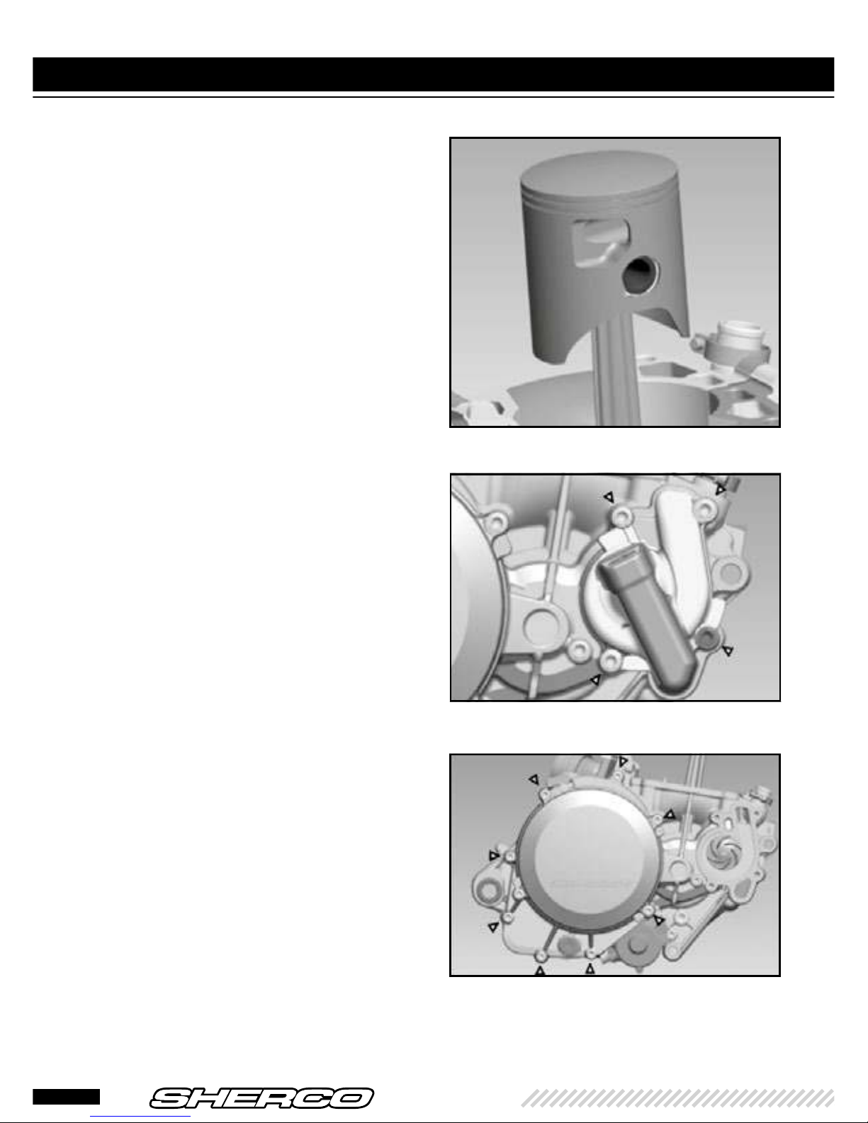
• Remove the piston pin clips.
• Remove the piston pin.
• Remove the piston and extract the needle
bearing from the connecting rod eye.
• Remove the header gasket.
14
250-300 SE-R
ENGLISH
REMOVING THE PRESSURE PLATE AND DISCS
• Loosen the pressure plate screws 1.
• Remove the screws, springs and spring cups.
• Remove the pressure plate and discs from
the housing.
• Remove the support piece
1
on the
primary shaft.
1
15
REMOVE THE ELECTRIC
STARTER
• Remove the 2 screws 2.
• Open the clutch boss lock washer
5
.
• Apply the 5749 tool
6
which is designed
to hold the boss, then loosen the nut.
• Remove the tool.
• Remove the boss, the crenellated washer,
the housing with the 2 needle cages.
REMOVING THE PRIMARY
TRANSMISSION
• Lock the pinion at the end of the
crankshaft with the 5206 tool 3.
• Unscrew the primary transmission nut
4
and then remove it with its conical washer.
2
3
4
6
5
DISMANTLING THE ENGINE (next)
16
250-300 SE-R
ENGLISH
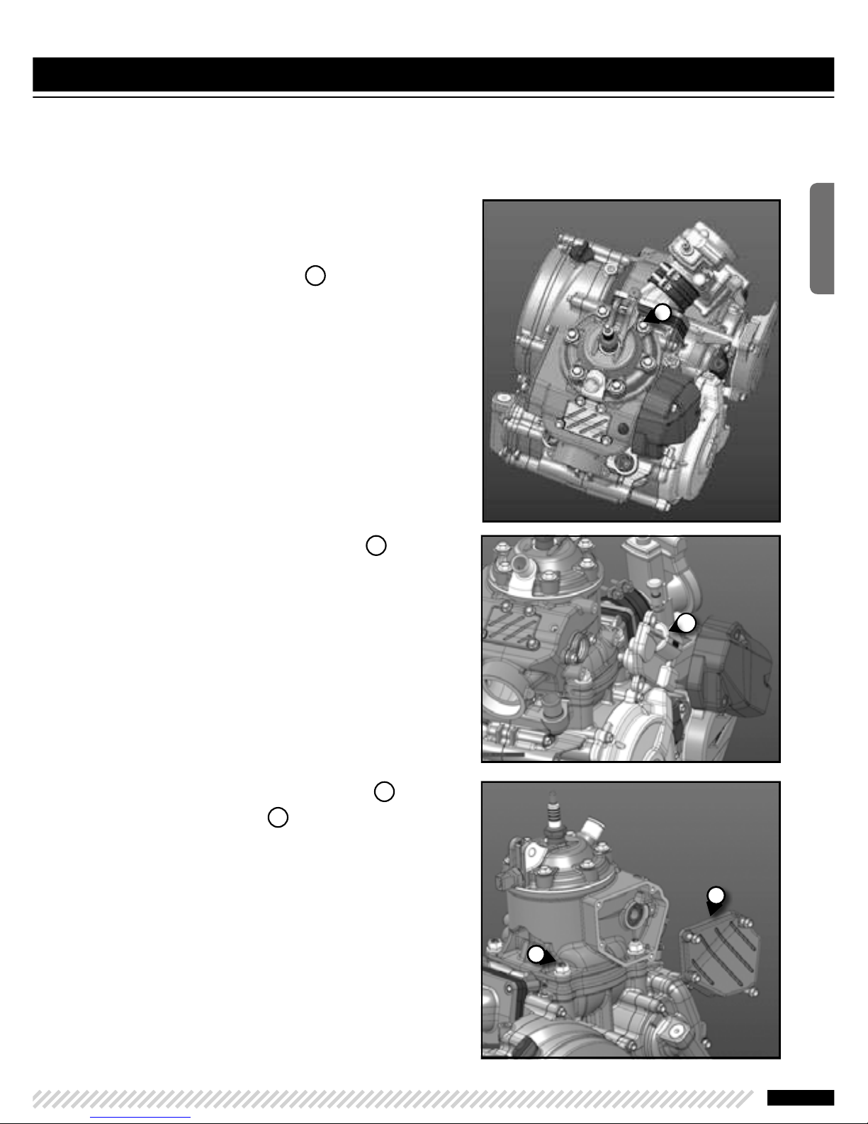
• Removing the primary transmission pinion
and the spacer 1 at the end of the
crankshaft.
PAY ATTENTION
To the pin and the o-ring.
The primary transmission pinion and the clutch
housing ring are paired, which is why they can not
be changed separately. Always replace them
together.
WARNING
Pay attention to the washer which remains at the
bottom of the housing.
PAY ATTENTION
To the star selector's indexing pin. the locking
lever should only be extracted if the housing is
changed.
• Loosen the Allen screw
2
and remove the
star selector 3.
REMOVING THE LOCKING
MECHANISM
• Push back the scorpion with a screwdriver
so that it is no longer in contact with the
star selector, then remove the selection
shaft.
• Then loosen the screw
4
and remove the
lever with its spring and spacer.
1
3
2
17
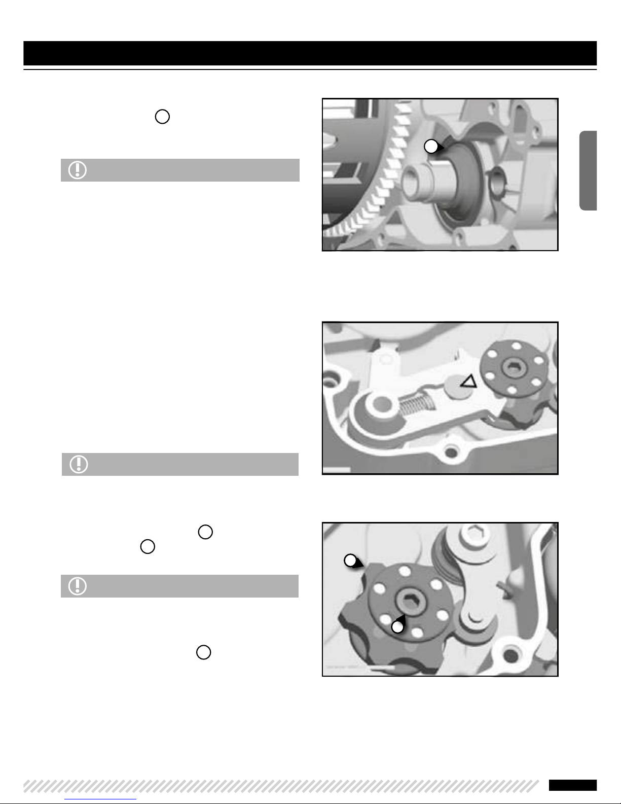
REMOVING THE IGNITION
HOUSING
• Remove the screws and extract the
ignition housing with its gasket.
REMOVING THE TORQUE
LIMITER AND THE STARTER
DRIVE
• Remove the 3 shoulder screws 1.
• Remove the torque limiter lug
2
.
• Remove the starter drive
3
.
• Remove the torque limiter
4
.
2
3
4
1
DISMANTLING THE ENGINE (next)
18
250-300 SE-R

ENGLISH
REMOVING THE IGNITION
• Hold the flywheel with the 4753 tool 1
and unscrew the shoulder nut.
• Position the R462 puller
2
and extract
the magnetic flywheel 3.
INTAKE PIPE AND VALVE BOX
• Remove the 4 THEP screws 4.
• Remove the pipe, the valve box, and their
respective gasket.
1
3
2
4
19
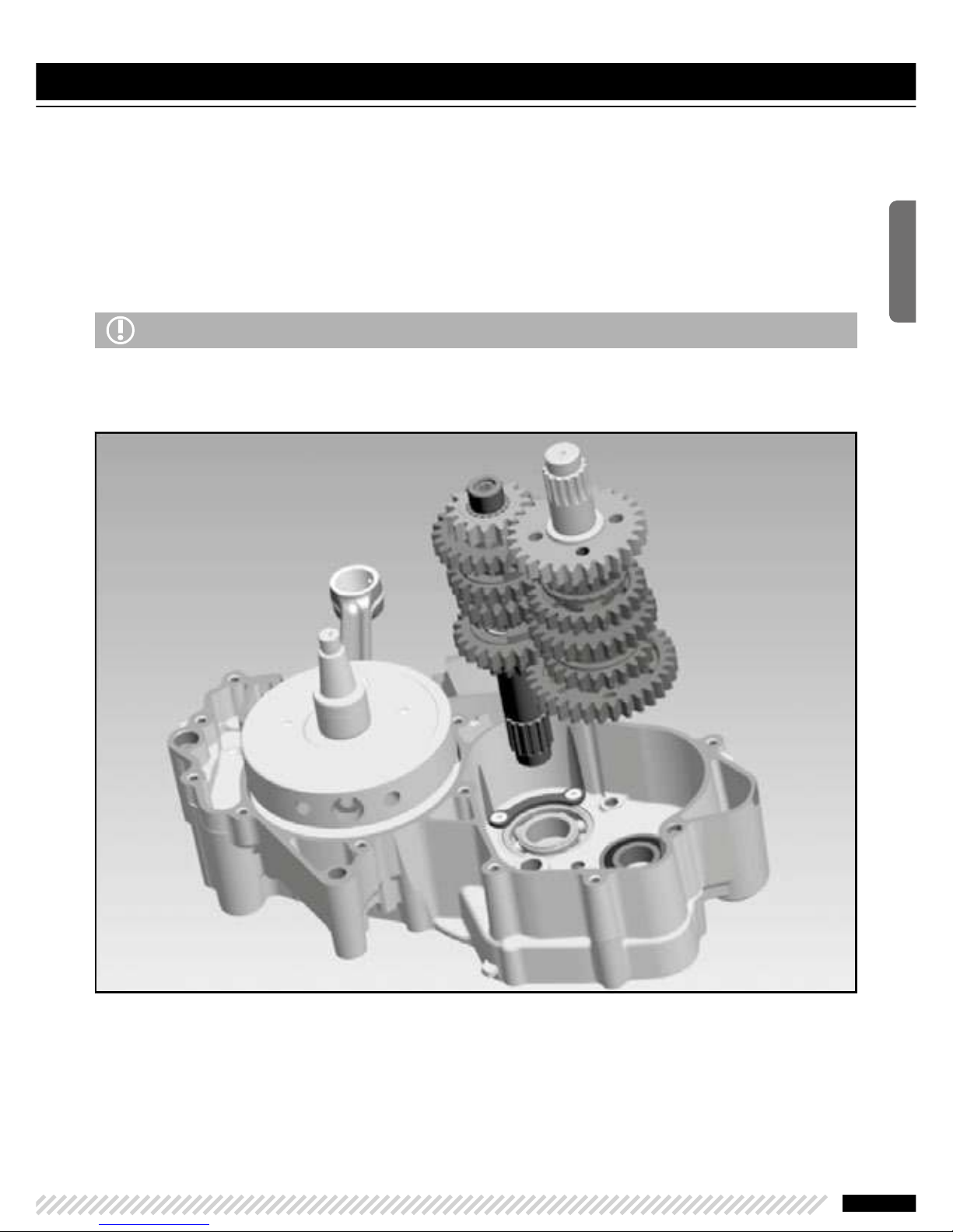
• Separate the half crankcases.
• Tilt the engine so that the ignition side is
facing you.
• Remove all the fixing screws.
• Remove the seal ring and its o-ring from
the gearbox output shaft.
• Lift the left half crankcase by lightly tapping
the gearbox output shaft with a plastic
mallet to separate it from the other half.
• Remove the half crankcase and the central
gasket.
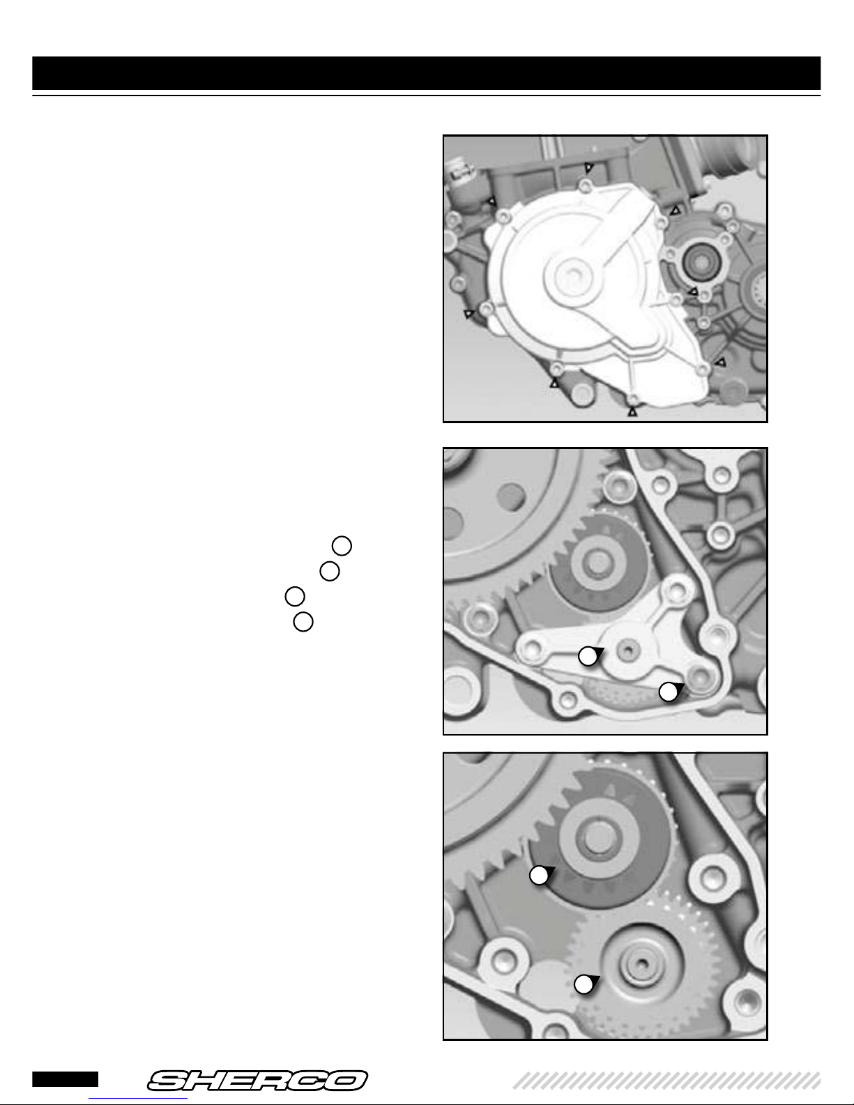
REMOVING THE GEAR
SELECTION
• Remove the gearbox lubrication tube 1.
• Remove the set ring from the primary
shaft
2
.
• Remove the two pins from the shift forks
3
and push the shift forks to the side to
release them from the cylinder.
• Remove the selection cylinder from its
bearing.
• Remove the shift forks.
• Remove the primary and secondary shaft
from their bearing together.
WARNING
Prising a screwdriver or other tool between the
half housings to separate them should be avoided
as much as possible. You may damage the gasket
surfaces.
WARNING
Pay attention to the gearbox shafts' set rings. They
can remain stuck inside the housing.
WARNING
When dismantling, take care not to lose the small
rollers 4 on the fork studs. identify which is the
corresponding fork for each roller to facilitate
reassembly.
1
2
3
3
4
DISMANTLING THE ENGINE (next)
20
250-300 SE-R
ENGLISH
REMOVING THE CONNECTING ROD ASSEMBLY
• Remove the connecting rod assembly from its bearing (if necessary by tapping lightly with a
plastic mallet on the end of the crankshaft).
• Clean all parts and check for wear. Replace them if necessary.
WARNING
When completely dismantling the engine, it is best to replace all gaskets, spi seals, o-rings and even
bearings.
21
 Loading...