

SHERCO 250 SEF-R,300 SEF-R Workshop Manual


1
CONTENTS
FORWARD ................................................................................................................................................. 3
MOTOR TOOLS 250 SEF-R and 300 SEF-R ...................................................................................................... 4
TECHNICAL SPECIFICATION ........................................................................................................................ 5
THE MOTOR ..................................................................................................................... 5
THE FRAME ................................................................ ...................................................... 6
STANDARD ADJUSTMENT .......................................................................................................................... 7
THE FORK ........................................................................................................................ 7
SHOCK ABSORBER .............................................................................................................. 8
OPERATIONS REQUIRING DEMOUNTING OR NOT ENGINE ............................................................................. 9
REMOVING / REINSTALLING THE MOTOR ................................................................................................... 10
REMOVING THE MOTOR ...................................................................................................... 10
REINSTALLING THE MOTOR ................................................................................................... 10
MOTOR .................................................................................................................................................. 11
REMOVING THE CYLINDER HEAD ............................................................................................. 11
MOTOR TOP END CONTROLS ................................................................................................. 13
Inspection of the cylinder for wear ..................................................................................................................... 13
Piston / cylinder clearance ................................................................................................................................. 13
Piston wear ........................................................................................................................................................ 14
Ring groove / piston ring .................................................................................................................................... 14
Ring end gap ...................................................................................................................................................... 14
Inspect the connecting rod, the piston pin and the piston for wear ................................................................... 14
Check the camshafts for wear ........................................................................................................................... 15
Checking the camshafts and camshaft journals for wear .................................................................................. 15
Eccentricity of the camshaft ............................................................................................................................... 15
Inspect the cylinder head for flatness ................................................................................................................ 16
Visually inspect the timing chain for damage ..................................................................................................... 16
Inspecter visuellement les patins de distributions .............................................................................................. 16
Valve – Guide clearance .................................................................................................................................... 16
REASSEMBLING THE TOP END OF THE MOTOR .............................................................................. 17
Reassemble the piston....................................................................................................................................... 17
Valve timing ........................................................................................................................................................ 19
Checking the valve clearance ............................................................................................................................ 21
Replacing the cam chain .................................................................................................................................... 21
DISASSEMBLING THE RIGHT SIDE ............................................................................................. 22
Clutch dismanting ............................................................................................................................................... 22
Inspect the clutch ............................................................................................................................................... 22
Check the clutch spring length ........................................................................................................................... 22
Reassembly of the clutch ................................................................................................................................... 22
Disassembling and inspecting the water pump ................................................................................................. 23
Changing the water pump shaft seal requires removing the clutch housing ..................................................... 23
Removing the clutch hub and the clutch basket ................................................................................................ 24
Reassembling the clutch hub components ........................................................................................................ 24
DISASSEMBLING THE LEFT SIDE .............................................................................................. 25
Disassembling the ignition case ......................................................................................................................... 25
Replacing the stator and sensor system ............................................................................................................ 25

2
Removing the rotor ............................................................................................................................................. 26
Inspect the freewheel and the needle bearings ................................................................................................. 26
Reassembling the ignition case ......................................................................................................................... 27
CRANKCASE / TRANSMISSION / CENTRAL CRANKCASES .................................................................... 28
Disassembling the transmission and the crankshaft .......................................................................................... 28
Checking the transmission components ............................................................................................................ 29
Checking the crankshaft..................................................................................................................................... 30
Checking the center crankcases ........................................................................................................................ 31
Reassembling the central crankcase assembly ................................................................................................. 32
TIGHTENING TORQUES ....................................................................................................... 35
CLEAN INJECTOR BODY ....................................................................................................... 37
Material............................................................................................................................................................... 37
Put down the injector body ................................................................................................................................. 37
Clean of injector body ........................................................................................................................................ 39
Replace the injector body................................................................................................................................... 39
SYNERJECT )
INJECTION SYSTEM INSTRUCTION MANUAL ..................................................................... 40
SYNERJECT ) INJECTION SYSTEM PRESENTATION ........................................................................... 40
SOFTWARE PRESENTATION .................................................................................................. 46
2.1- Connection with Keyless system ................................................................................................................ 46
2.2- Software setup : configuration menu .......................................................................................................... 48
2.3- Menu update and synchronization .............................................................................................................. 49
USING THE SOFTWARE ....................................................................................................... 51
ELECTRICAL INSTALLATION CHECKING .................................................................................................... 64
CONTROLS OF THE SENSORS ................................ ................................................................ .................. 66
CONTROL TPS SENSOR ....................................................................................................... 66
VALUES OF TEMPERATURE SENSOR ......................................................................................... 67
CABLE DIAGRAM ................................................................................................................................ ..... 68
Injection beam .................................................................................................................................................... 68
250 SEF light system cable diagram ................................................................................................................. 71
300 SEF light system cable diagram ................................................................................................................. 72
250 SEF-R Racing light system cable diagram ................................................................................................. 73
300 SEF-R Racing light system cable diagram ................................................................................................. 74
Flasher installation cable diagram ..................................................................................................................... 75
Fan cable diagram ............................................................................................................................................. 76

3
FORWARD
This manual is designed primarily for skilled mechanics working in a properly equipped
workshop. The execution of the operations in this manual requires a strong mechanical
knowledge and specific SHERCO tools designed for the 250 SEF-R and 300 SEF-R engine.
This workshop manual is a supplement to the SHERCO 250 SEF-R and 300 SEF-R owner’s
manual.
4
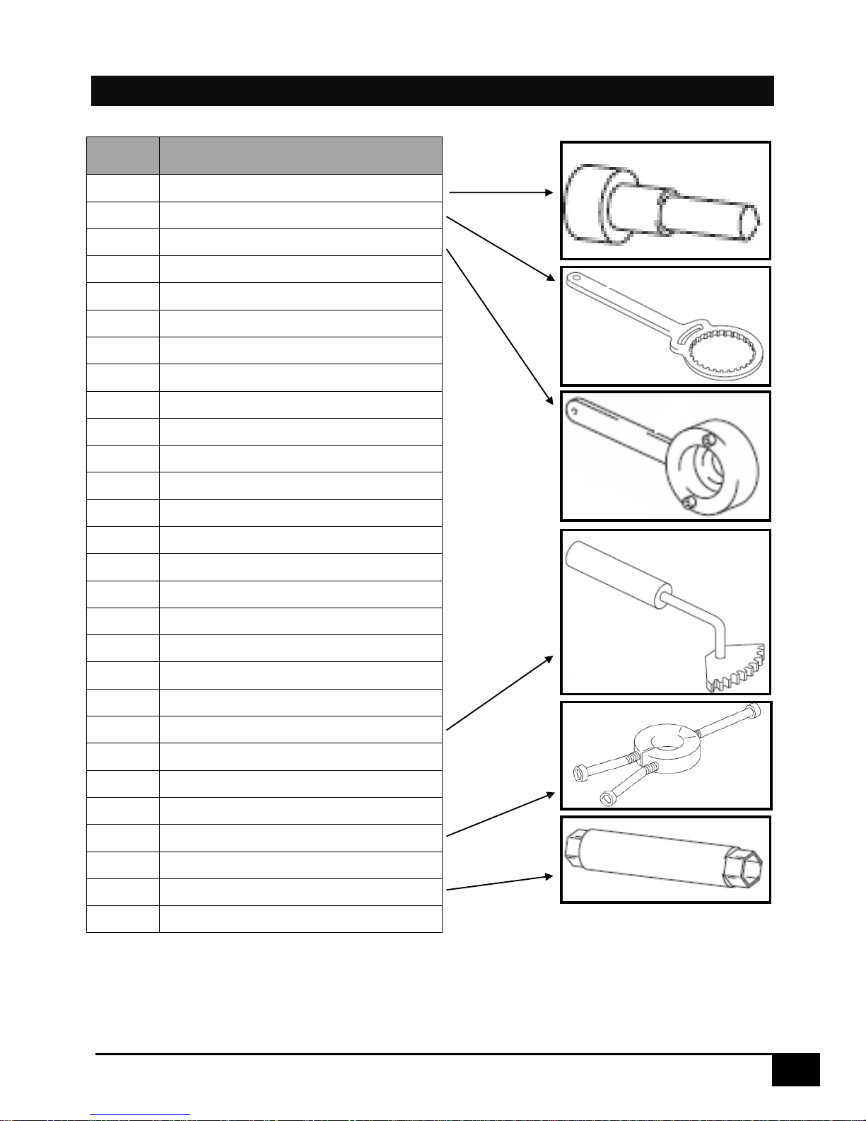
MOTOR TOOLS 250 SEF-R and 300 SEF-R
TOOL
REF
DESIGNATION
1819
Dead point
1814
Clutch holder tool
4753
Ignition tool
2067
Swingarm tool
2068
Freewheel tool
2069
Oil seal tool (Gear box exit)
2070
Oil level gauge tool
2071
Bearing tool 6905 (Gear selector drum)
2072
Bearing tool 6222 (Clutch shaft)
2079
Bearing tool 6203 left (Balancer)
2080
Oil seal tool 8x18x5
1822
Bearing tool (Water pump shaft)
2078
Oil seal 36x57x7,5 right (Crankshaft)
2077
Bearing tool 4905 right (Balancer)
2074
Bearing tool 6003 (Gear shaft)
1968
Oil seal tool (Water pump)
2075
Piston tool
2076
Bearing tool (Crankshaft)
1816
Ring tool
1821
Engine support tool 250
1817
Pinion tool
1818
Piston support
2073
Resort tool
R462
Flywheel puller
R464
Ring extractor
R450
Gear selector oil seal tool
3785
Spark key
6267
Shunt for keyless system
5
TECHNICAL SPECIFICATION
THE MOTOR
250 SEF-R
300 SEF-R
Type
Liquid cooled single cylinder 4 strokes engine
Displacement
248.6 CC
303.7 CC
Bore/Stroke
76/54.8mm
84/54.8mm
Compression ratio
13.2 :1
12.85:1
Fuel
Without lead 95 or 98
Valve timing
4 valves, DOHC driven by tooth type chain
Admission valve diameter
29mm
30mm
Exhaust admission valve
25mm
Thickness admission valve
0.15-0.2mm
Thickness exhaust valve
0.2-0.25mm
Crankshat bearing
2 roller bearing
Piston
Aluminium forge
Lubrification
Lubrication under pressure with 2 trochoidal pumps
Motor oil
1 litre SAE 10W40
Primary reduction ratio
21 :70
Gear box :
1st
2nd
3rd
4th
5th
6th
6 speed
14 : 33
17 : 30
19 : 28
21 : 26
23 : 24
25 : 22
Final transmission
13 X 49
13 X 48
Clutch
Multi-disk in oil bath. Hydraulic command
Ignition system / Batterie
Electric start/12V 4Ah
Electronic injection
Synerject

6
TECHNICAL SPECIFICATION
THE FRAME
Frame
Semi-perimeter CrMo steel with aluminum subframe
Fork
SACHS USD Gold Series 48mm dia. (standard) & WP USD
48mm dia. (racing)
Rear suspension
WP Suspension with separate cylinder
Travel Front/Rear
300/330mm
Front brake
disc Ø 270mm (standard), Ø 256mm (racing)
Rear brake
disc Ø 220mm
Brake disc
2.7mm front et 3.6mm rear
Front tire
90/90-21’’
Rear tire
140/80-18’’
Pressure TT
0.9 bar
Fuel tank capacity
9.7l with 1l of reserve
Angle of the steering column
27.3°
Wheel base
1480mm
Weight (without fuel)
102 kg
7
STANDARD ADJUSTMENT
THE FORK
Standard adjustment - Fork Sachs USD Gold Series Ø48MM
Compression
Turn clockwise to the stop, then
back of 12 clicks
Rebound
Turn clockwise to the stop, then
back off 12 clicks
Spring
4.5N/mm
Fork oil
SAE 5
Oil capacity
600cm3
Oil level
130mm
Standard adjustment - Fork WP USD Gold Series Ø48MM
Compression
Comfort
20 clicks back
Standard
13 clicks back
Sport
8 clicks back
Rebound
Comfort
18 clicks back
Standard
13 clicks back
Sport
10 clicks back
Preload
Comfort
2 turns
Standard
4 turns
Sport
6 turns
Spring stiffness
Rider weight : 143 -165 lbs
4.0N/mm
Rider weight : 165- 187 lbs
4.2 N/mm (original)
Rider weight : 187- 210 lbs
4.4N/mm
Type of oil
SAE 4
Oil level measurement (fork compressed and spring
removed) from the top of the fork tube
110mm
8
STANDARD ADJUSTMENT
SHOCK ABSORBER
Standard adjustment - WP Shock absorber
Low-speed compression
Comfort
20 clicks back
Standard
15 clicks back
Sport
12 clicks back
High-speed compression
Comfort
2.5 clicks back
Standard
2 clicks back
Sport
1.5 clicks back
Rebound
Comfort
15 clicks back
Standard
13 clics en arrière
Sport
11 clics en arrière
Spring stiffness
Rider weight : 143 -165 lbs
48N/mm
Rider weight : 165- 187 lbs
51N/mm (origine)
Rider weight : 187- 210 lbs
54N/mm
9
OPERATIONS REQUIRING DEMOUNTING OR NOT ENGINE
Removing engine
Not demounting engine
Crankshaft •
Gear box •
Crankshaft bearing
•
Gear Box bearing
•
Piston
•
Cylinder
•
Cylinder head •
Valve timing •
Ignition
•
Pinion of ignition system
•
Freewheel •
Clutch
•
Water pump •
Oil pump •
Gear selection •

10
REMOVING / REINSTALLING THE MOTOR
REMOVING THE MOTOR
ATTENTION
To remove the engine, you must remove the swing arm axle, the swing arm and the rear wheel.
To keep the bike from falling, remember to support the chassis with an appropriate jack.
Drain (refer to the owner’s manual)
- the engine oil
- the engine coolant
Remove the seat.
Disconnect the battery.
Remove the fuel tank and its covers.
Disconnect all the electrical wiring connectors from the engine. (Starter, TPS sensor,
water temperature sensor, coil, fuel injector).
Remove the exhaust.
Remove the ignition coil.
Remove the fuel injector body.
Remove the chain.
Remove the chain guard.
Remove the clutch actuating cylinder.
ATTENTION
When the clutch actuating cylinder is removed the piston is loose. Hold the piston it in place
using a plastic strap.
Remove all of the water hoses connected to the motor.
Remove the left radiator.
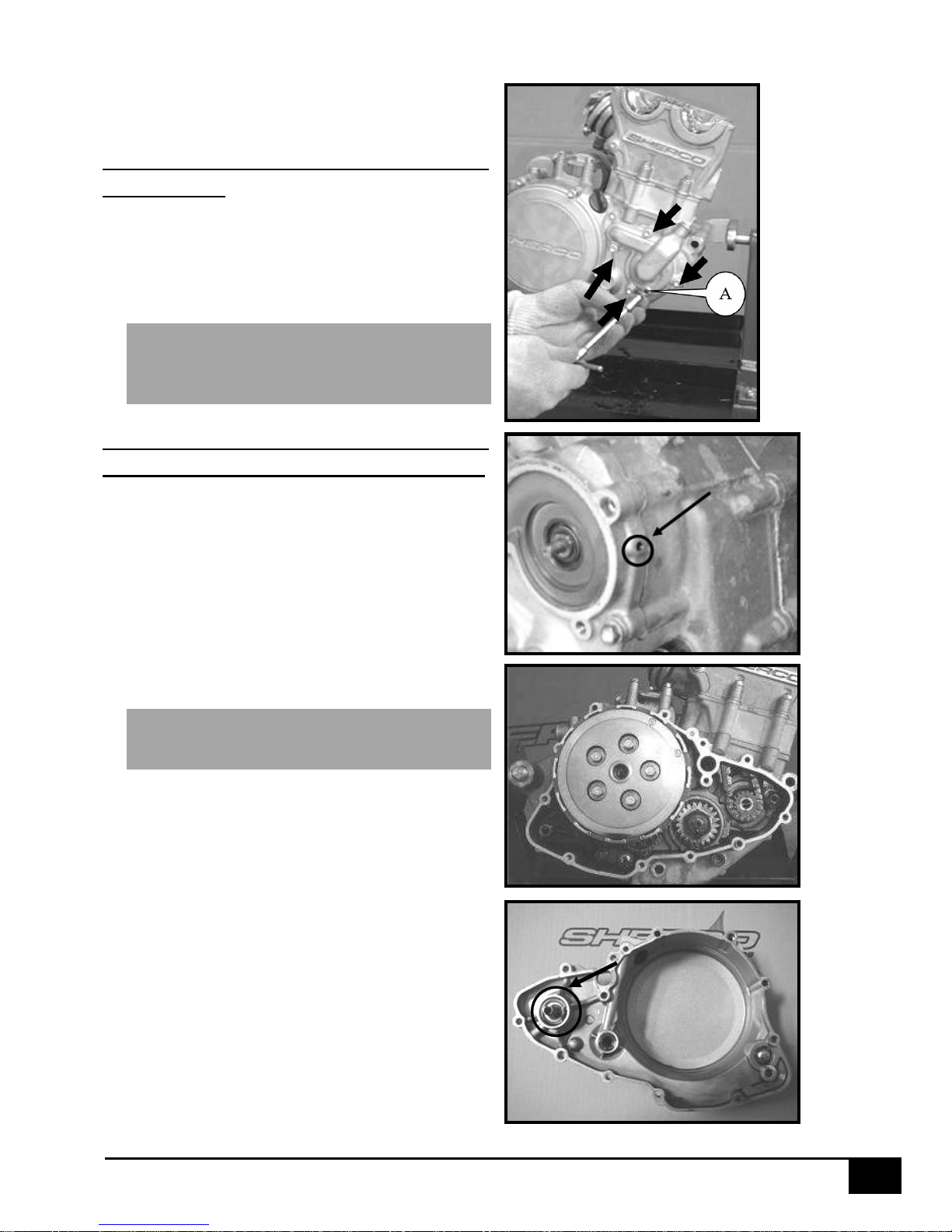
Loosen all of the engine bolts [A].
Loosen the swing arm bolt.
Remove the brackets that attach the cylinder head to the chassis.
Remove the motor mounting bolts.
Remove the swing arm bolt.
Remove the motor.
REINSTALLING THE MOTOR
The motor should be reinstalled in the frame in the reverse order of how it was removed. The
following torque values should be utilized.
Tightening torques:
Motor mounting bolts: 60Nm
Swing arm axle nut: 100 Nm
Clutch receiver screws: 10 Nm
Cylinder head bracket bolts: 23Nm
Exhaust mounting bolts: 10Nm
11
MOTOR
For additional details refer to the parts catalog 250 SEF-R _ 300 SEF-R
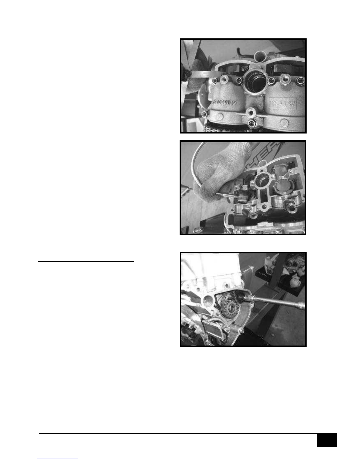
REMOVING THE CYLINDER HEAD
Remove the spark plug.
Remove the valve cover.
Remove the three valve cover screws.
ATTENTION : These three screws are equipped with o-rings ref: 0900.
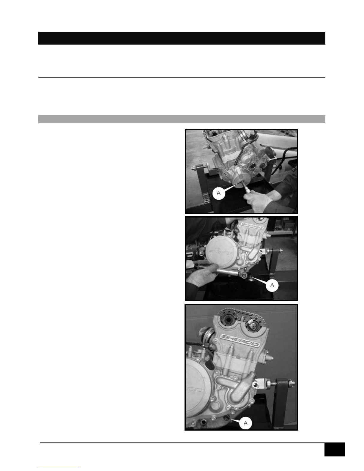
Remove the cap from the ignition
cover [A].
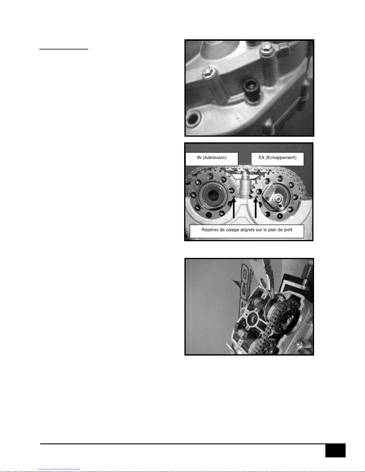
Remove the timing control plug [A]
Turn the engine counterclockwise in
order to align the timing marks on
the crankshaft with the marks on the
timing gear. Install the special tool
that locks the engine at Top Dead
Center [A] (ref 1819)
12
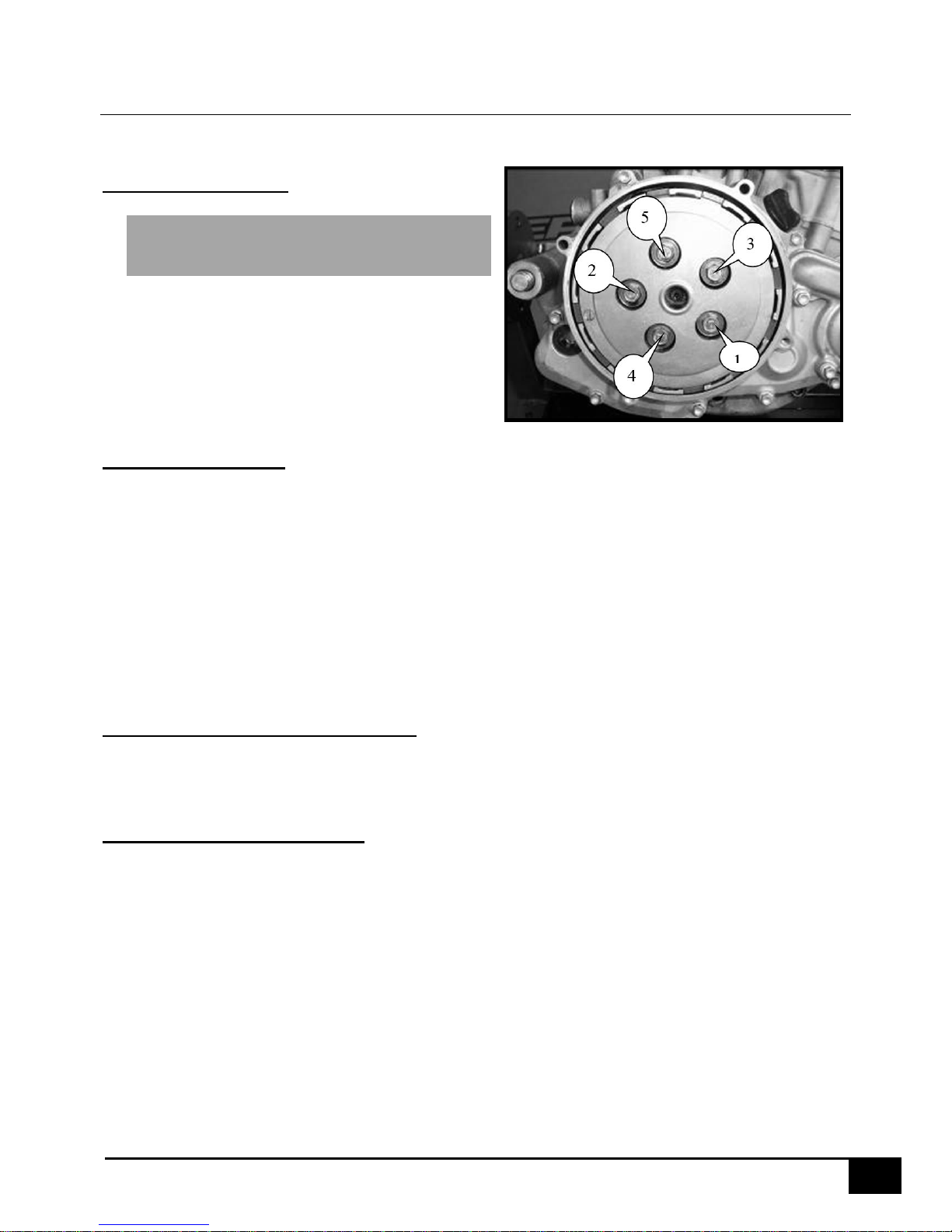
Remove the screws from the cam
chain tensioner as shown in the
photo.
Remove the cam chain tensioner.
Remove the spark plug well.
Remove the camshaft bearing
journal. Starting on the inside,
remove the screws
In a criss cross manner (see the
numbers on the photo).
Remove the exhaust camshaft
retaining clip.
Remove the exhaust camshaft.
Remove the intake camshaft
retaining clip.
Remove the intake camshaft.
Remove the two nuts M6 and the
washer.
13
Remove the cylinder head bolts (Be
sure to loosen them in the correct
direction).
ATTENTION : Black bolt N°1 on the
picture is longer, 3 bolts are identical.
Remove the cylinder head.
Remove the head gasket and the
cylinder.
MOTOR TOP END CONTROLS
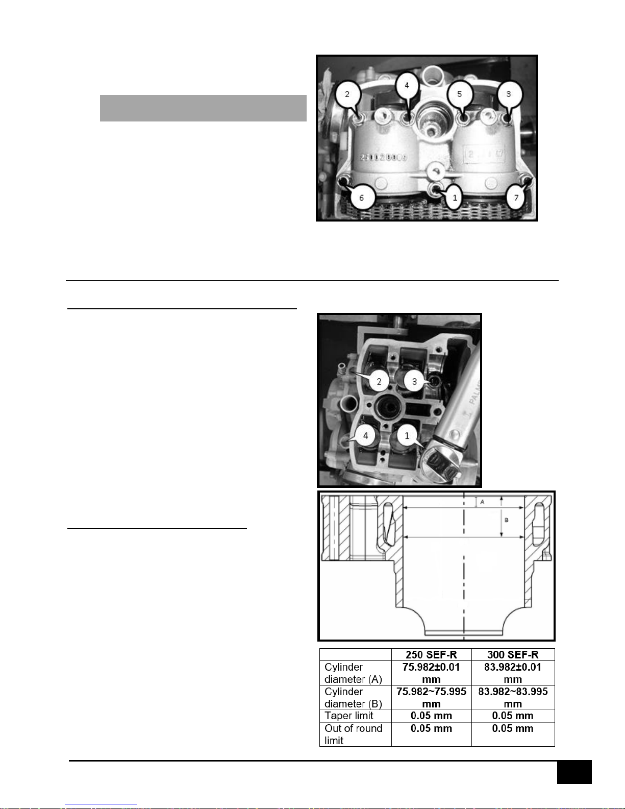
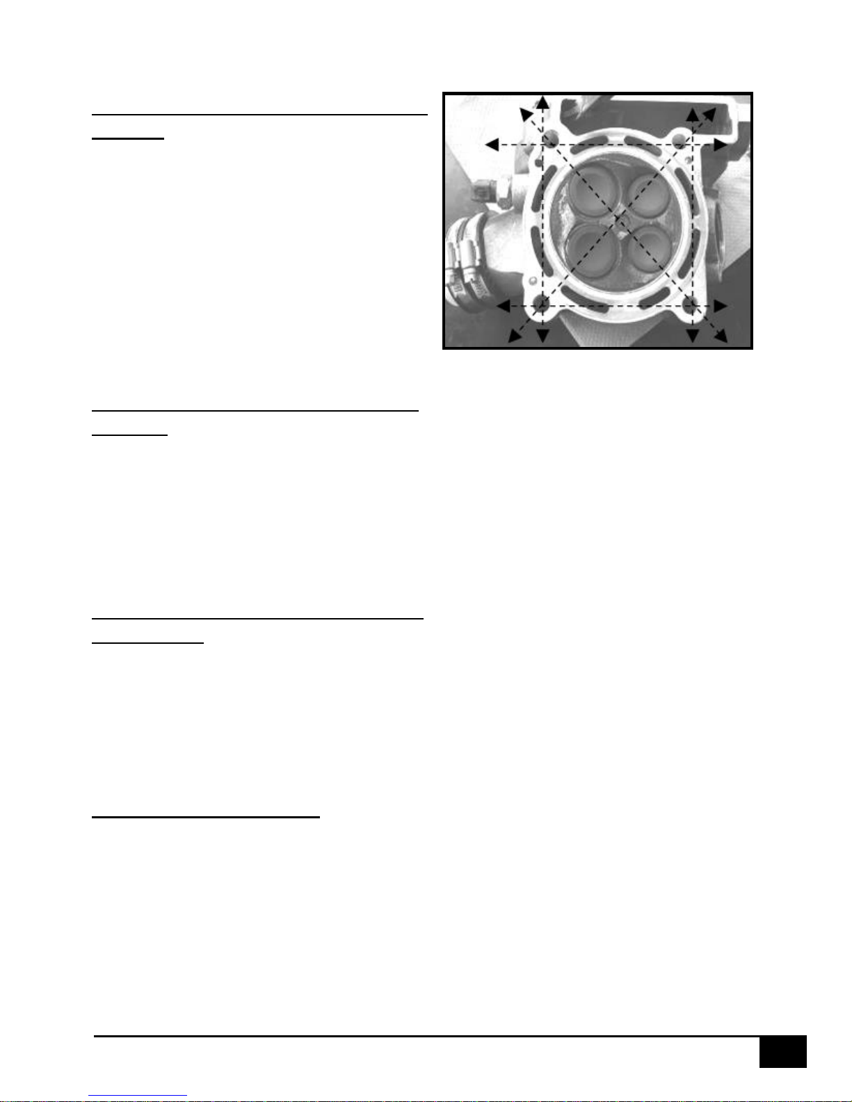
Inspection of the cylinder for wear
Measure the inside diameter of the cylinder
when it is cold.
Inspect the inside of the cylinder for any
scratches or other evidence of abnormal wear.
If the cylindecar is badly damaged or worn it
should be replaced.
Since the cylinder does not wear in a uniform
manner measure in from side to side and up
and down as shown.
If the inside measurement of the cylinder
exceeds the tolerance limit it must be
replaced.
(A)=10 mm
(B)=25 mm
Piston / cylinder clearance
To determine the piston / cylinder clearance as
accurately as possible it is sufficient to
measure the piston and the cylinder, and then
calculate the difference between the two
values. Measure the diameters as shown.
Piston / cylinder clearances
Standard 0.03 – 0.05 mm
Limit 0.10 mm
14
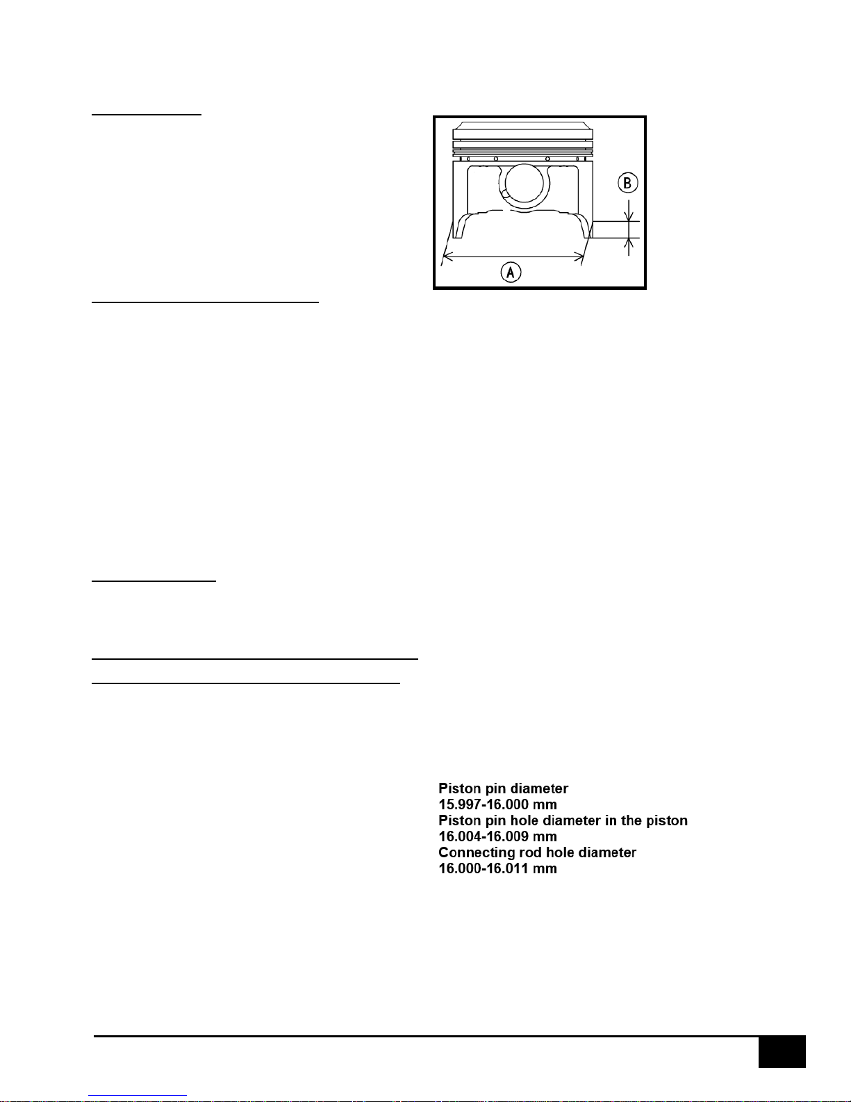
Piston wear
Using a micrometer measure the outside
diameter of the piston [A] 10mm [B] above
the bottom of the piston and at right angles
to the axis of the piston.
If the outer diameter of the piston is below
the tolerance it must be replaced.
Piston 250 SEF-R= 75.950±0.005 mm
Piston 300 SEF-R= 83.950±0.005 mm
Ring groove / piston ring
Using a feeler gauge measure the
clearance between the piston ring and the
ring groove.
Check in several places to determine the
actual clearance if the clearance is greater
than the maximum, replace the piston ring
and if necessary the piston.
Ring groove / piston ring
Standard
Compression ring: 0.030-0.065 mm
Limit 0.13 mm
Oil control ring: 0.020-0.055 mm
Limit 0.13 mm
Ring end gap
Compression ring : 0.3-0.4 Limit 0.7 mm
Oil control ring : 0.3-0.5 mm
Inspect the connecting rod, the
piston pin and the piston for wear
Visually inspect the circlips in place.
If they appear worn or distorted replace
them. If the hole for the circlips appears
worn replace the piston.
Measure the piston pin with a micrometer.
If at any place on the pin the diameter is
below the limit replace the piston pin.
Measure the diameter of the piston pin
holes in the piston and the hole in the
connecting rod. If the one or more holes in
the piston are incorrect replace the piston.
If the diameter of the hole in the connecting
rod is incorrect, replace the connecting rod.
15
Check the camshafts for wear
Remove the camshafts.
Measure the heights [A] of the camshaft
lobes with a micrometer.
If the cams are worn beyond the limits,
replace the cams.
Camshaft height limit 250
Exhaust: 31.245 mm
Intake: 32.145 mm
Camshaft height limit 300
Exhaust: 31.977 mm
Intake: 32.145 mm
Checking the camshafts and
camshaft journals for wear
Measure the clearance between the
camshaft and the camshaft journals using
plastigage [A].
Lubricate the fixing bolts with engine oil and
tighten to the proper torque.
Tightening torque
Camshaft journal mounting bolts: 10 Nm
If any of the measurements are over the
limit, then measure the diameter of each
journal.
Camshaft / journal clearance
Standard: 0.020 – 0.062 mm
Limit: 0.15 mm
If the diameter of the journal is below the
limit replace the camshaft and measure
again.
Camshaft journal diameter
Standard: 23.05 – 23.25 mm
Limit 23.02 mm
If the clearance is outside of the tolerance
limits, replace the entire cylinder head.
Eccentricity of the camshaft
Measure the camshasft runout.
If it is out of tolerance, replace the camshaft.
Runout : Less than 0.03 mm
16
Inspect the cylinder head for
flatness
Place the cylinder head on the workbench
Using a precision straight edge [A] and a
feeler gauge check the head for warpage;
check in several places as shown in the
photo.
If the warpage is above the limit, repair if
possible. If the damage is severe replace the
head.
Cylinder head warpage:
Limit = 0.05 mm
Visually inspect the timing chain for
damage
Inspect the timing chain by flexing it to
determine if there are any tight spots. If tight
spots are found it should be replaced.
Check the automatic chain adjuster and
make sure that it is not in the last ratchet
notch.
Inspecter visuellement les patins de
distributions
Visually inspect all of the cam chain
tensioner channel guides and pads
including the ones on the cylinder head
cover.
Change as necessary.
Valve – Guide clearance
Intake :
Mini clearance : 0.02 mm
Maxi clearance : 0.045 mm
Escape :
Mini clearance : 0.04 mm
Maxi clearance : 0.065 mm

17
REASSEMBLING THE TOP END OF THE MOTOR
Reassemble the piston
Install the piston rings on the piston with
the end gaps as shown in the photo, the
compression ring goes in the top groove
and the oil control ring goes in the bottom
groove.
A Lower expander end gap
B Lower piston ring end gap
C Upper expander end gap
D Upper piston ring gap
ATTENTION : The expander rings do not
have a top or bottom; however the oil
control ring and the compression ring must
be installed with the « N » mark facing up.
Apply engine oil to the wrist pin internal
bore in the piston.
Carefully note the piston orientation (the
small cut outs are on the exhaust side)
Install the locating pins [B].
Install the base gasket [C].
Use special tool number 1821 to maintain
the piston in the correct location [A].
ATTENTION : Use the same head gasket
(thickness 0.3 or 0.4mm depending on the
model).
Place one of the cir clips in the special tool
number 2075 as shown in the photo; install
the clip close to one end of the tool.
Use the tool to set up the clip for
installation on the wrist pin.
Install the circlip on the wrist pin.
Mettre le poussoir de l’outil pour mettre en
place le clip.
Mettre l’axe de piston.
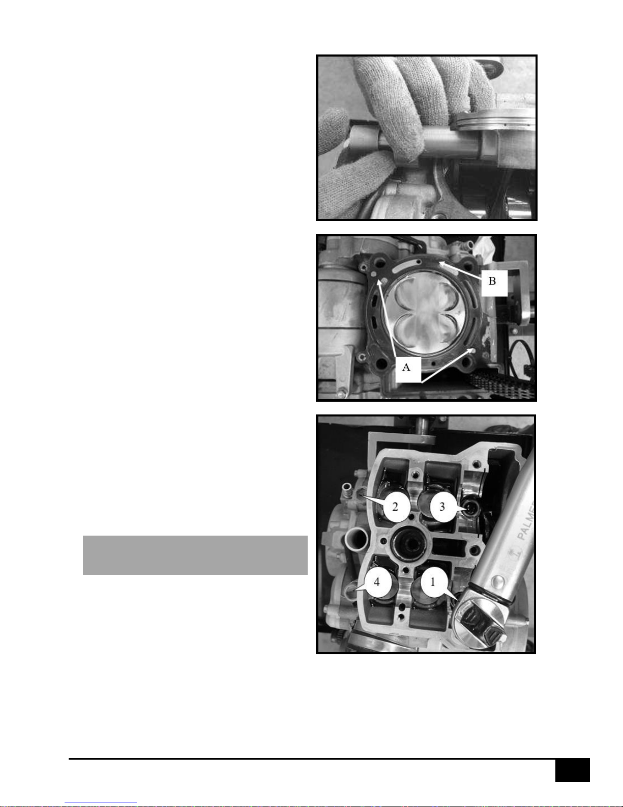
18
Install the wrist pin into the piston and
connecting rod using the tool and lightly
tapping with a hammer.
Install the opposite circlip, using the special
tool.
Install the cylinder over the piston using an
appropriate ring compressor.
Install the two cylinder head locating pins
[A].
Install the head gasket [B].
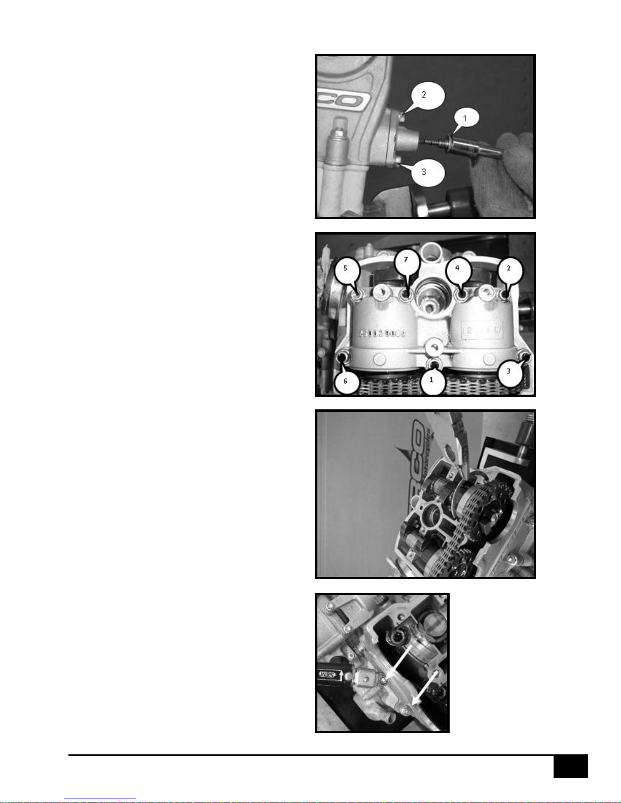
Install the cylinder head.
Install the head bolts noting the different
lengths; tighten them using two passes in
the order shown in the photo.
Install and tighten the two M6 nuts.
Cylinder head torque:
Studs 1st pass: 30 Nm
2nd pass: 45 Nm
Nuts M6: 10 Nm
ATTENTION : The two internal bolts are of
different length and are equipped with
washers.
19
Valve timing
Verify that tool number 1819 is still
properly installed.
Install the intake cam.
Install the exhaust cam.
(see the photo for how to set the timing
marks)
Install the camshaft retaining clips.
Apply moly disulfide grease to the
camshafts.

20
Install the camshaft retaining cover. (pay
careful attention to the tightening order).
Camshaft retaining cover torque
10Nm
ATTENTION : The screw n°1 is a M6 X 35
Install the camshaft chain tensioner using
a new gasket.
Torque the two fixing bolts to:
10Nm
Install the cam tensioner adjusting bolt
(pay attention to the o-ring).
Torque the tensioner adjusting screw
to: 10Nm
Remove the special tool number 1819.
Rotate the engine a few times to make
sure that the valve timing is correct.
Finally check the valve timing using the
timing marks.
Replace the cap that was removed to
install tool number 1819.
Torque the cap to:
8Nm
Replace the spark plug well.
ATTENTION : Make sure that the o-rings
are installed on the spark plug well.
Apply a thin coat of silicone to the
camshaft end cap bores.
Replace the valve cover.
Install the valve cover installation bolts.
Torque the bolts to:
8Nm
21
Checking the valve clearance
The valve clearance must be checked
when the engine is cold.
Remove the spark plug and the valve
cover.
Remove the timing plug from the
crankcase.
Install special tool number 1819.
With a feeler gauge measure the clearance
between the bucket and the cam.
Valve clearance
Intake 0.15 – 0.20 mm
Exhaust 0.20 – 0.25 mm
If the clearance is not correct then change
the discs in order to obtain the correct gap.
Remove the discs with a magnet.
Measure the thickness of the disc and
replace with one of the correct thickness.
Select the appropriate disc from the
existing parts catalog.
Replacing the cam chain
Remove the camshafts (see the chapter on
the motor top end).
Remove the clutch cover (see the chapter
on « Right side » removing the clutch).
Remove the chain tensioner adjuster.
Remove the cam chain.
Inspect the cam chain (see « visually
inspecting the cam chain »).
Install the cam chain in the opposite
manner in which it was removed.
Reinstall the cam tensioner bolt and
tighten to the correct torque.
Torque the cam tensioner bolt to:
10Nm.
22
DISASSEMBLING THE RIGHT SIDE
For additional details see the parts catalog 250 SEF-R and 300 SEF-R.
Clutch dismanting
Install special tool number 1819.
ATTENTION : Only use this tool for
disassembling the clutch, do not use it to
remove the hub fixing nut.
Remove the 4 screws that retain the clutch
cover.
Remove the 5 pressure plate screws (see the
photo).
Sort the discs and make sure they are
trimmed and smooth.
Make sure that the clutch hub rotates freely.
Inspect the clutch
Inspect the discs to make sure they are
trimmed and smooth.
Friction plate thickness
Standard: 2.95
Limit: 2.7
Deformation limit: 0.3mm
Steel disc thickness
Standard: 1.4
Limit: 1.3
Deformation limit: 0.3mm
Check the clutch spring length
Measure the free length of the clutch springs.
Standard : 37.29mm
Limit : 36.5mm
Reassembly of the clutch
Soak the friction discs in engine oil.
Replace the discs on the hub by starting with
a friction disc and then a steel disc ending
with a friction disc.
Replace the pressure plate.
Install the 5 springs.
Install the 5 screws and tighten in an
alternating order (see the disassembly photo).
Torque the screws to:
10Nm
23
Reinstall the clutch cover, inspect the o-ring
and replace if it is damaged.
Disassembling and inspecting the
water pump
Drain the coolant by removing screw [A].
Remove the screws from the water pump
housing.
Remove the water pump impeller using a 10
mm socket.
ATTENTION : If the seal is leaking, coolant
will come out of the weep hole (see photo). In
order to change the seal the clutch housing
must be removed.
Changing the water pump shaft seal
requires removing the clutch housing
Remove the clutch housing.
Remove the clip from the water pump shaft.
Remove the water pump shaft.
Remove the roll pin.
Heat the clutch case in an over to 70°.
Extract the bearing.
Put some grease like “molikote Dx” on the lips
of the oil seal.
Change the seal using special tool number
1968.
ATTENTION : make sure the seal is installed
properly, you should see the spring when you
look at the seal. (see photo).
Check the bearing, if it requires changing use
special tool number 1822.
Reinstall the parts in the reverse order of their
removal. Pay careful attention to the clutch
housing locating pins, always install a new
paper gasket and if necessary install a new oring seal on the water pump housing.
Tighten the water pump housing screws
to:
10Nm.
Tighten the coolant drain plug to:
6Nm.
 Loading...