


1


TECHNICAL SPECIFICATION
FOREWORD ........................................................ 2
TOOLS LIST 250-300 SE ........................................ 3
TECHNICAL SPECIFICATION ............................. 4
ENGINE ............................................................... 4
CARBURETOR .................................................. 4
CYCLE PART ....................................................... 5
STANDARD ADJUSTMENT ................................. 6
FORK .................................................................. 6
SHOCK ABSORBER ............................................. 7
OPERATIONS REQUIRING DISASSEMBLY OR NOT
ENGINE ............................................................... 8
REMOVING THE ENGINE ................................. 9
REASSEMBLING THE ENGINE IN THE FRAME
........................................................................ 9
DISMANTLING THE ENGINE .......................... 10
❱❘ Gear box drainage ................................................. 10
❱❘ Removing the pinion and selector .......................... 10
❱❘ Removing the cylinder head / the cylinder / the
piston ......................................................................... 11
❱❘ Removing the clutch housing ................................. 12
❱❘ Removing the pressure plate and discs ................. 13
❱❘ Remove the electric starter .................................... 13
❱❘ Removing the primary transmission ....................... 14
❱❘ Removing the primary transmission ....................... 15
❱❘ Removing the torque limiter and the starter drive .. 15
❱❘ Removing the ignition ............................................. 16
❱❘ Intake pipe and valve box ...................................... 16
❱❘ Remove the gear selection .................................... 17
❱❘ Removing the connecting rod assembly ................ 18
❱❘ Connecting rod assembly ....................................... 18
CHECKING ENGINE COMPONENTS ............. 19
❱❘ Balance weight, checking the external dimensions 19
❱❘ Radial play of the connecting rod head .................. 19
❱❘ Checking the crankshaft run out ............................ 19
❱❘ Piston ..................................................................... 20
❱❘ Gap spacing ........................................................... 20
❱❘ Piston pin check ..................................................... 20
❱❘ Checking the wear condition of the cylinder .......... 20
❱❘ Functional check .................................................... 21
❱❘ Valve stop learning after cylinder reassembly ....... 24
❱❘ Valve box intake pipe sleeve .................................. 24
❱❘ Clutch ..................................................................... 25
❱❘ Gearbox .................................................................. 25
❱❘ Valve box and intake pipe ...................................... 33
❱❘ Gearbox output pinion............................................ 33
❱❘ Starter drive assembly ........................................... 33
❱❘ Mounting the ignition and its cover ........................ 34
❱❘ Mounting the electric starter .................................. 34
SYNERJECT) INJECTION SYSTEM
INSTRUCTION MANUAL .................................... 35
INTRODUCTION SYNERJECT SYSTEM ......... 35
1.1- Synerject system .............................................. 35
1.2- Description Exxodiag diagnostic .................. 35
1.3- Diagnostic tool kit contents. ........................... 36
1.4- Installation of the diagnostic tool ................... 36
PRESENTATION OF THE SOFWARE ............. 40
2.1- Connection with Keyless system ................... 40
2.2-
Software settings: configuration menu
2.3- Update menu and synchronization ................ 43
3 - Using
3.1- Identification ..................................................... 45
3.2- Reading the default codes .............................. 46
3.3- Erasing default codes ...................................... 48
3.4- Test the actuators ............................................ 49
3.5- Updating the ECU ............................................. 51
3.6- Screen printing function.................................. 53
TORQUES TABLE ........................................... 54
CARBURETOR ADJUSTEMENT TABLE ........ 55
❱❘ SE 250-Carburetor adjustments table ................... 55
❱❘ SE 300-Carburetor adjustments table ................... 56
CHECKING THE LOAD CIRCUIT .................... 57
❱❘ Static control value ................................................. 57
❱❘ Dynamic control values .......................................... 57
the software
.............................................. 45
.................... 42
T° SENSOR, ENGINE RPM SENSOR, HIGH
VOLTAGE COIL ............................................... 58
WIRING DIAGRAM .......................................... 59
❱❘ Main harness .......................................................... 59
❱❘ Standard lights harness .......................................... 60
❱❘ Racing lights harness .............................................. 61
❱❘ Accessories harness ................................................ 62
REASSEMBLING THE ENGINE ...................... 27
❱❘ Assembling the half crankcases ............................. 27
REASSEMBLING THE ENGINE ...................... 28
❱❘ Gear selection mechanism ..................................... 28
❱❘ Primary transmission and clutch ............................ 29
❱❘ Clutch discs, pressure plate ................................... 30
❱❘ Clutch housing........................................................ 30
❱❘ Piston and cylinder ................................................. 31
❱❘ Squish table ............................................................ 32
❱❘ Cylinder head ......................................................... 32
1

FOREWORD
This manual is primarily intended for qualified mechanics working in a properly equipped
workshop.
A solid knowledge of mechanics and the specific SHERCO tools for the 250 SE-R and
300 SE-R engines are required to perform the various operations.
This workshop manual complements the SHERCO 250 SE-R and 300 SE-R user manual
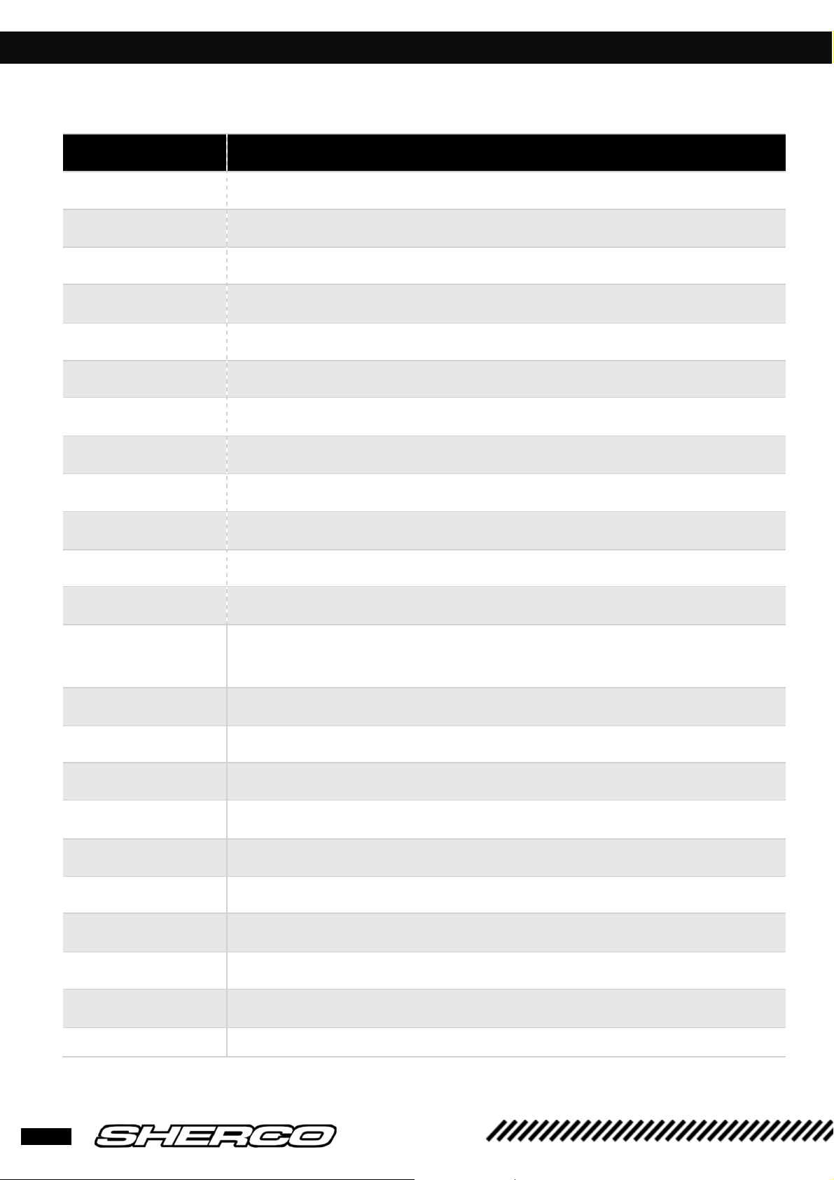
TOOLS LIST 250-300 SE
Tool reference Designation
5749 Clutch block
4753 Ignition block
2067 Swing-arm pin tool
R467 Right crankcase primary shaft bearing tool
R465 Secondary shaft bearing tool
5397 Gearbox output shaft bearing tool
R446 Gearbox output spi tool
5398 Barrel selection bearing tool
5399
R469 Right crankcase crankshaft bearing tool
Left crankcase crankshaft bearing tool
5400
5401
5402
1968
1821
5206
2073
R462
R464
R453
R444
Clutch side crankshaft spi tool
Ignition side crankshaft spi tool
HK0808 needle cage tool
(water pump, starter drive double pinion, starter drive)
Water pump spi seal tool
Engine support
Primary pinion block tool
Spring block (pin selection)
Magnetic flywheel puller
Crankshaft ring extractor
Selector axis bearing assembly tool
Selector spi seal tool
6267
4967
3
Diagnostic Key less tool
Diagnostic briefcase
250/300 SE
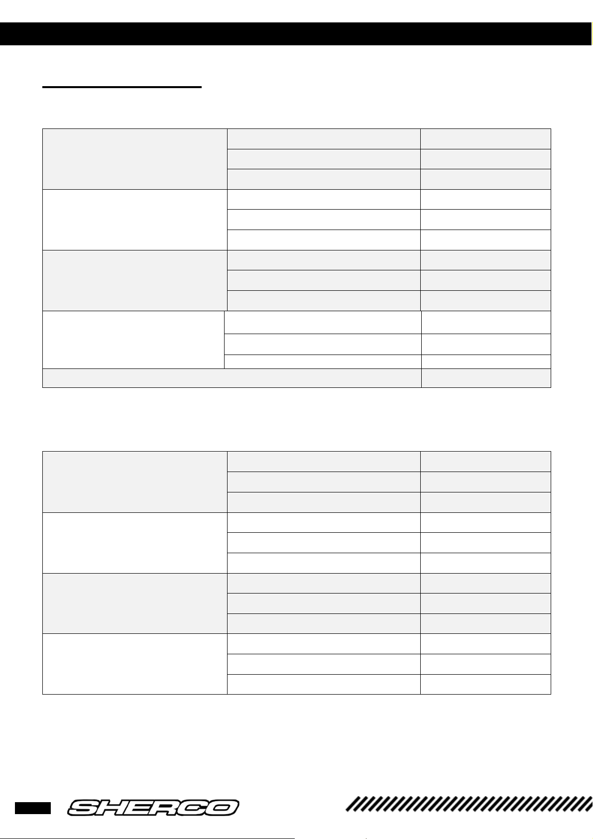
TECHNICAL SPECIFICATION
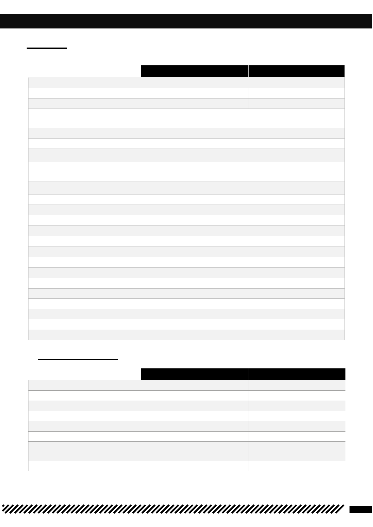
ENGINE
Type
Capacity
Bore/Stroke
Petrol
Cooling
Ignition system
Spark plug
Distance between spark
plug electrodes
Piston
Engine oil
Primary transmission
Gearbox : 6 speeds
1st 14 : 32
2nd 15 : 26
3rd 29 : 27
4th 21 : 24
5th 23 : 22
6th 25 : 21
Final transmission
Clutch
Starter
Battery
249.32 CC
66.4/72 mm
Cast aluminum
750 ml SAE 10W40
27 : 75
Oil bathed multi disks, hydraulic control
Electric starter
12V 4Ah
Unleaded with an octane rating of at least 98 mixed with 2-
250 300
Single cylinder 2 stroke liquid cooling
stroke oil (2 %)
Liquid with forced circulation
Synerject electronic ignition
NGK BR7ES/DENSO W22ESRU
0.7 mm
14 X 49
293.14 CC
72/72 mm
Alternator
220W
CARBURETOR
Carburetor type
Needle position
Jet needle
Main jet
Idle jet
Choke jet
Air regulating screw
opening
Valve spacing
KEA 162 (KEA 115) KEA 172 (KEA 115)
KEP 40 (KEA38) KEP 42 (KEA 38)
85 (50) 85 (50)
3rd position from the top
N°7 N°7
KEIHIN PWK 36S AG KEIHIN PWK 36S AG
250 300
3rd position from the top
N1EG (N84K) N8RE (N84K)
1T 1/4 1T 1/2
4
TECHNICAL SPECIFICATION
Frame
Semi
-
perimeter CrMo
steel with aluminum sub frame
Angle of the steering column
CYCLE PART
Fork
Rear suspension
Travel Front/Rear FACTORY 330/330mm
Front brake rotor Ø 260mm
Rear brake rotor Ø 220mm
Brake disc Limit : 2.7mm front et 3.6mm rear
Front tire 90/90-21’’
Rear tyre 140/80-18’’
Pressure front / Rear 0.9 bar
Fuel tank capacity 10.4Ll with1 liter of reserve
Wheel base 1480mm
KAYABA USD Ø48mm Closed cartridge(FACTORY)
WP XPLOR USD Ø48mm (RACING)
KAYABA suspension with separate cylinder (FACTORY)
WP suspension with separate cylinder (RACING)
Aluminum swing arm
RACING 300/330mm
27.3°
Weight (without fuel) 119 kg
5
250/300 SE
STANDARD ADJUSTMENT
Compression
Rebound
Spring
Fork oil
Compression
Rebound
Preload
Spring stiffness
Type of oil
Spring length with preload spacer
Quantity of oil
FORK
Factory settings
Racing settings
– Fork KAYABA USD Ø48 mm
Comfort 20 clicks back
Standard 13 clicks back
Sport 8 clicks back
Comfort 18 clicks back
Standard 13 clicks back
Sport 10 clicks back
Rider weight
Rider weight
Rider weight
01M 345 CC
– Fork WP XPLOR suspension USD Ø48mm
Comfort 18 clicks back
Standard 15 clicks back
Sport 12 clicks back
Comfort 18 clicks back
: 65-75 kg 4.0N/mm (Original)
: 75-85 kg 4.2N/m
: 85-95 4.4N/m
Standard 15 clicks back
Sport 12 clicks back
Comfort +0 tours
Standard +0 tours
Sport +6 tours
Rider weight
Rider weight
Rider weight
Oil level measurement (fork compressed and spring
removed) from the top of the fork tube
: 65 - 75 kg 4.2N/mm
: 75 - 85 kg 4.4N/mm (Original)
: 85 - 95 kg 4.6N/mm
SAE 4
474 mm
606ml
100mm (min30-max 120 mm)
6
Low
-
speed compression
High
-
speed compression
Rebound
Spring stiffness
Low
-
speed compression
High
-
speed compression
Rebound
Spring stiffness
STANDARD ADJUSTMENT
SHOCK ABSORBER
Factory Settings
– KAYABA shock absorber
Comfort 20 clicks back
Standard 14 clicks back
Sport 12 clicks back
Comfort 2,5 turns back
Standard 1.5 turns back
Sport 1 turn back
Comfort 15 clicks back
Standard 13 clicks back
Sport 11 clicks back
Type of oil
Racing Settings
Rider weight : 65-75 kg
Rider weight : 75-85 kg
Rider weight : 85-95 kg
K2C
– WP suspension shock absorber
Comfort 17 clicks back
Standard 12 clicks back
Sport 9 clicks back
Comfort 2 turns back
Standard 1.5 turns back
Sport 1 turn back
Comfort 16 clicks back
Standard 14 clicks back
50N/mm
46N/mm
48N/mm (original)
7
Sport 12 clicks back
Rider weight : 65-75 kg
Rider weight : 75-85 kg
Rider weight : 85-95 kg
250/300 SE
51N/mm
54N/mm (original)
57N/mm
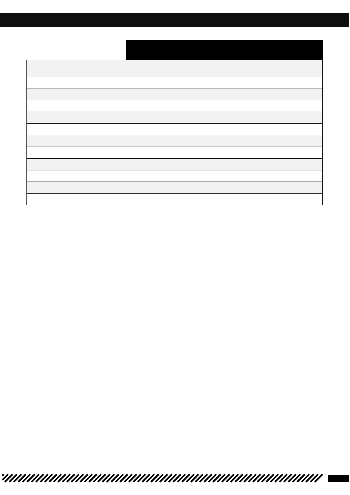
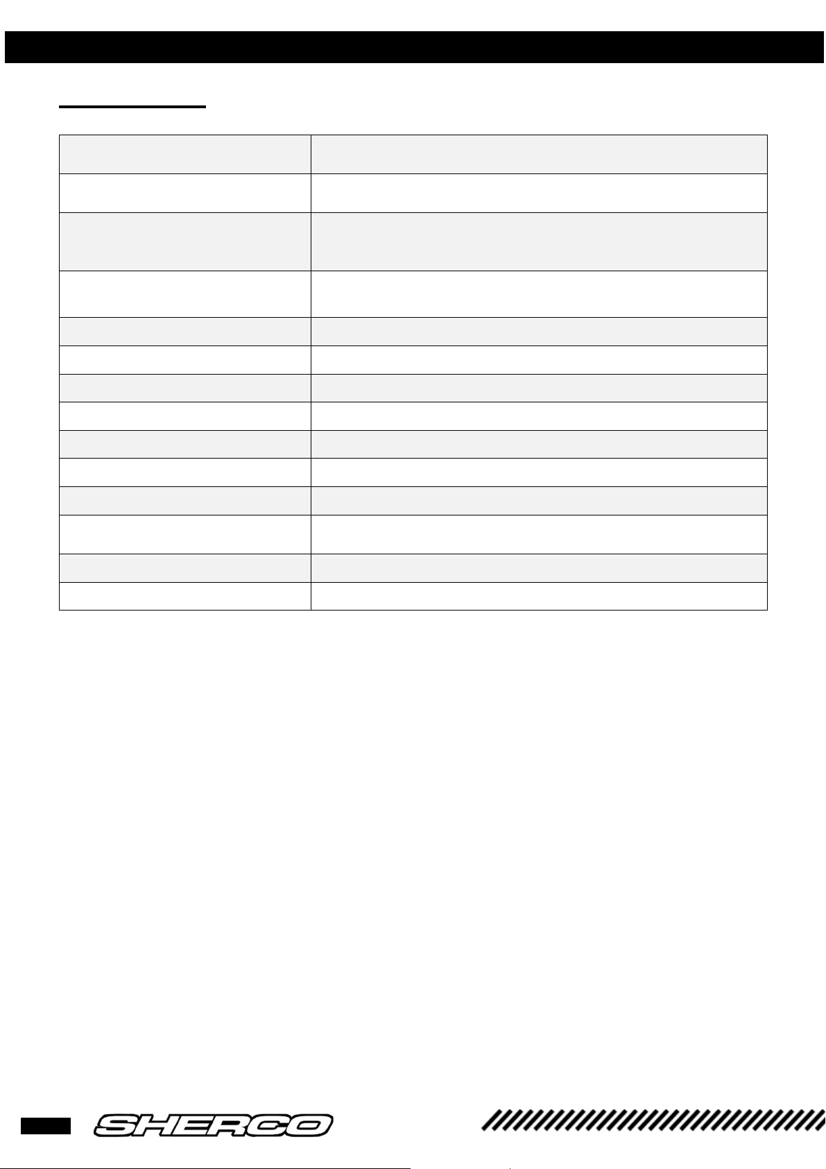
OPERATIONS REQUIRING DISASSEMBLY OR NOT ENGINE
Operation requiring engine
Operation not requiring engine
Crankshaft
(including
the crank
Complete gearbox
Crankshaft bearing
Gearbox bearing
Piston
Cylinder
Cylinder head
Ignition
Starter gear set
Complete clutch
Water pump
Speed selection assembly
kit)
removal
•
•
•
•
removal
•
•
•
•
•
•
•
•
8
REMOVING / REISTALLING THE ENGINE
WARNING
WARNING
REMOVING THE ENGINE
To remove the engine, you must remove the swing arm's pivot bolt to detach the rear
wheel/swing arm assembly. Secure the chassis with a jack to prevent the motorcycle
from overturning.
• Drain (refer to the owner’s manual)
- the engine oil
- the engine coolant
• Remove the seat.
• Disconnect the battery.
• Remove the fuel tank and its covers.
• Disconnect all the electrical wiring connectors from the engine.
(Starter, TPS sensor, water temperature sensor, coil, fuel injector)
• Remove the exhaust.
• Remove the ignition coil.
• Remove the carburetor.
• Remove the chain.
• Remove the chain guard.
• Remove the clutch slave cylinder.
When the clutch slave cylinder is removed, the piston is no longer held in place. Secure
the piston with a plastic collar.
• Remove all of the water hoses connected to the engine.
• Remove the left radiator.
• Loosen all of the engine bolts.
• Loosen the swing arm bolt.
• Remove the brackets that attach the cylinder head to the chassis.
• Remove the engine mounting bolts.
• Remove the swing arm bolt.
• Remove the motor.
REASSEMBLING THE ENGINE IN THE FRAME
The motor should be reinstalled in the frame in the reverse order of how it was removed. The following
torque values should be utilized.
Tightening torques:
Engine mounting bolts: 60Nm
Swing arm axle nut: 100 Nm
Clutch receiver screws: 10 Nm
Cylinder head bracket bolts: 23Nm
Exhaust mounting bolts: 10Nm
9
250/300 SE
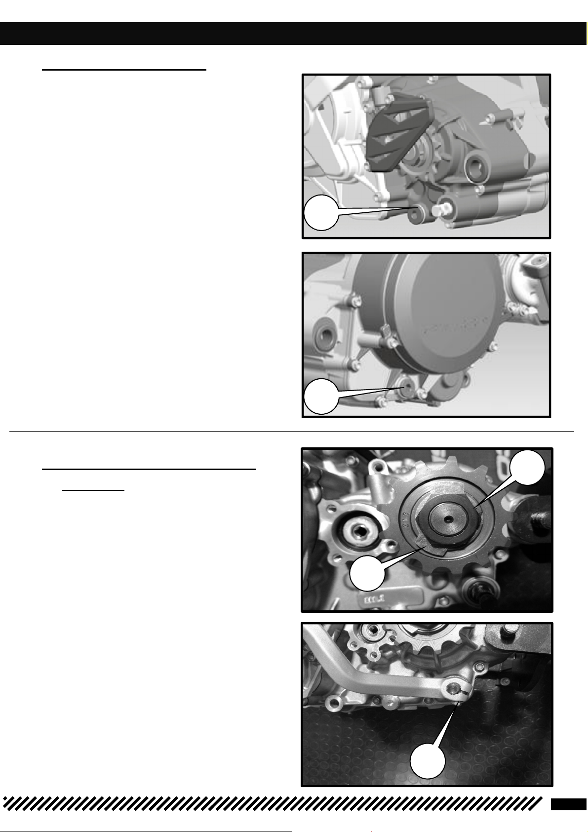
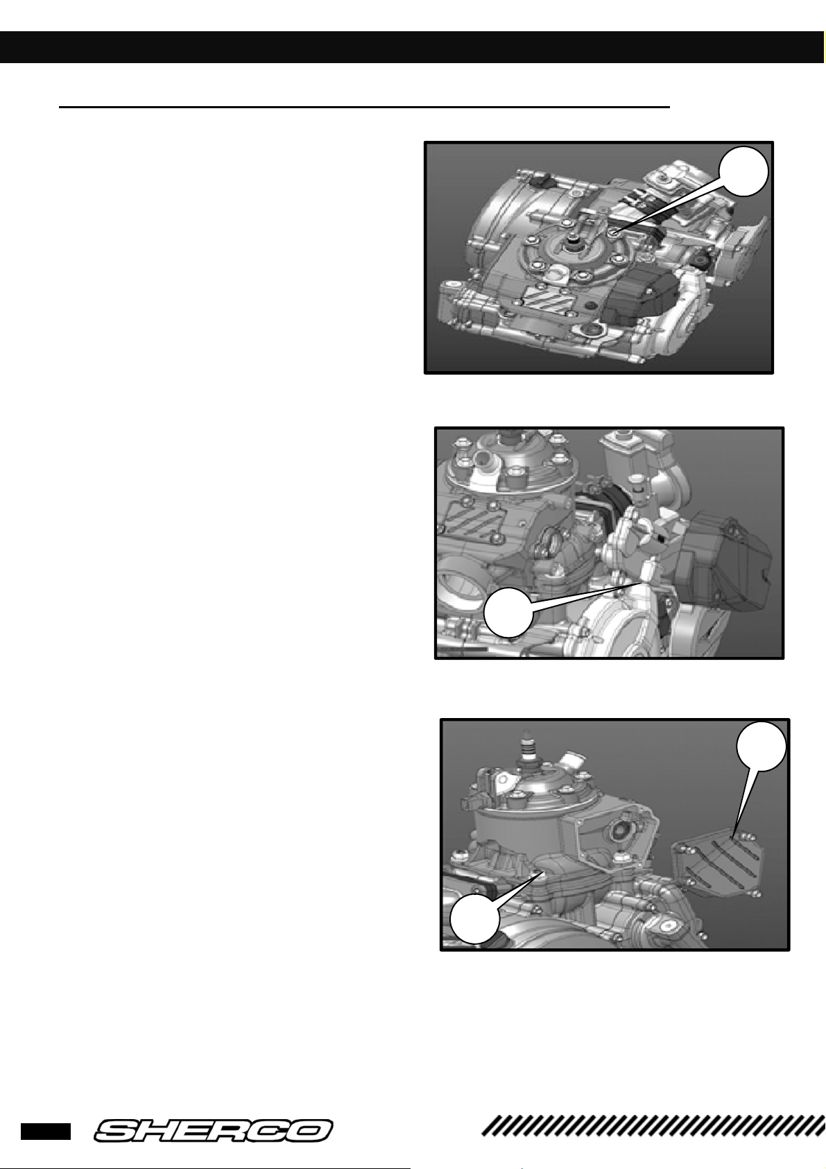
DISMANTLING THE ENGINE
1
2
3
4
5
1
❱❘ Gear box drainage
• Remove drainage plugs
oil
flow out.
[1]
and
[2],
let the
❱❘ Removing the pinion and
selector
•
Unfold the safety washer tab
device.
•
Remove the gearbox output pinion
•
Remove the screw first
the selector.
•
Release the clutch control rod.
[3]
using a punch
[5]
first and then
[4].
10
DISMANTLING THE ENGINE
1
2
3
4
❱❘ Removing the cylinder head / the cylinder / the piston
•
Remove the shoulder screws
cashers, remove
two O-rings
the cylinder head and the
[1]
the copper
•
Remove the exhaust valve actuator
• Remove the exhaust chamber cover.
• Remove the 4 screws
• The cylinder and remove it.
• Mask the cover.
[4]
on the base of
[2]
11
250/300 SE

DISMANTLING THE ENGINE
• Remove the piston pin clips.
• Remove the piston pin.
• Remove the piston and extract the needle
bearing from the connecting rod.
•
Remove the gasket
❱❘ Removing the clutch housing
•
Remove the screws and the water pump
cover.
•
Remove the gasket
• Remove the screws and extract the clutch
housing.
• Remove the gasket
.
12
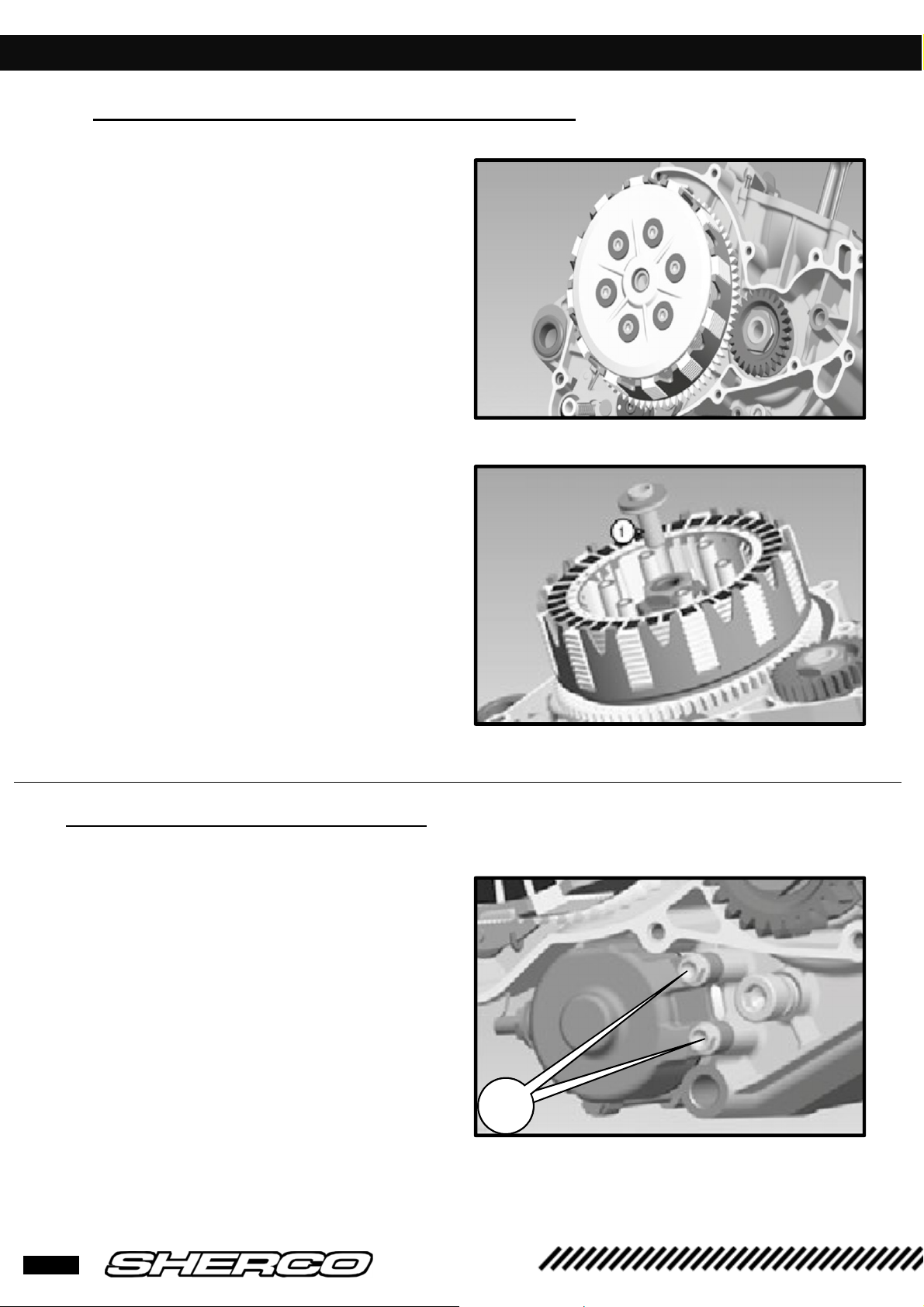
DISMANTLNG THE ENGINE
3 2
❱❘ Removing the pressure plate and discs
• Loosen the pressure plate screws
• Remove the screws, springs and springs
cups.
• Remove the pressure plate and discs from
housing.
• Remove the support part
shaft
[1]
on the primary
❱❘ Remove the electric starter
• Remove the 2 screws
[2]
13
250/300 SE
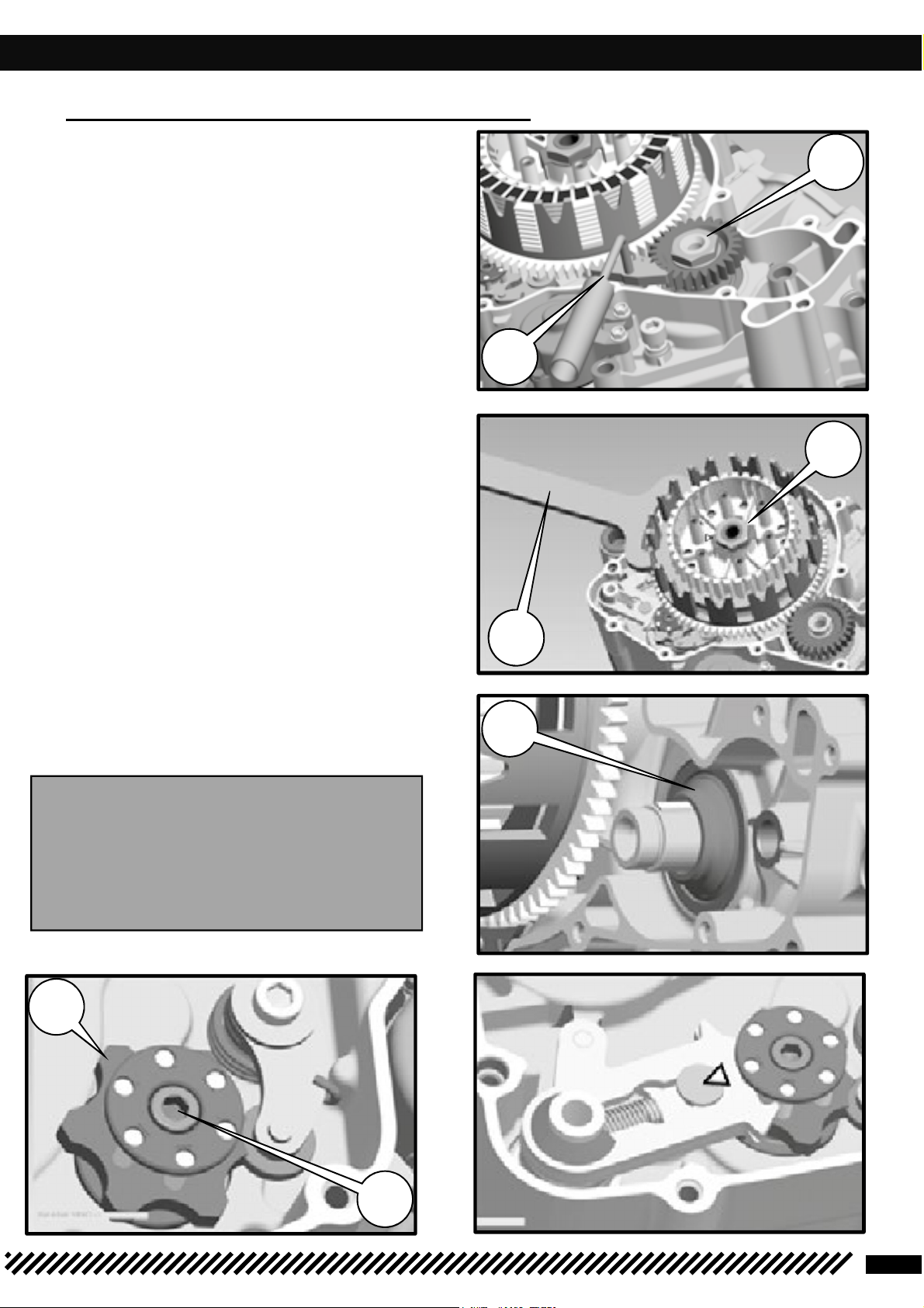
DISMANTLING THE ENGINE
WARNING
housing ring
4
3
6
6
1
3
2
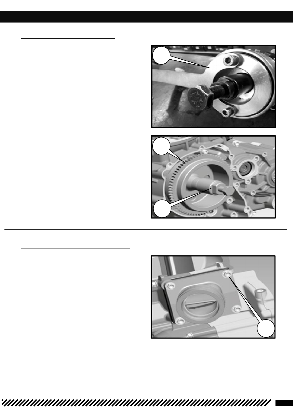
❱❘ Removing the primary transmission
• Lock the pinion at the end of the crankshaft
with the 5206 tool
[3]
• Unscrew the primary transmission nut
and then remove it with its conical washer
• Open the clutch boss lock washer
• Apply the 5749 tool
hold the boss, then loosen the nut.
• Remove the tool.
• Remove the boss the crenellated washer,
the housing with 2 needle cages
[6]
which is designed to
[5]
[4]
• Removing the primary transmission pinion
and the spacer
crankshaft
To the pin and the o-ring.The primary
transmission pinion and the clutch
are paired, which is why they can not be
changed separately. Always replace them
..
[1]
together.
at the end of the
14
DISMANTLING THE ENGINE
2
1
2
2
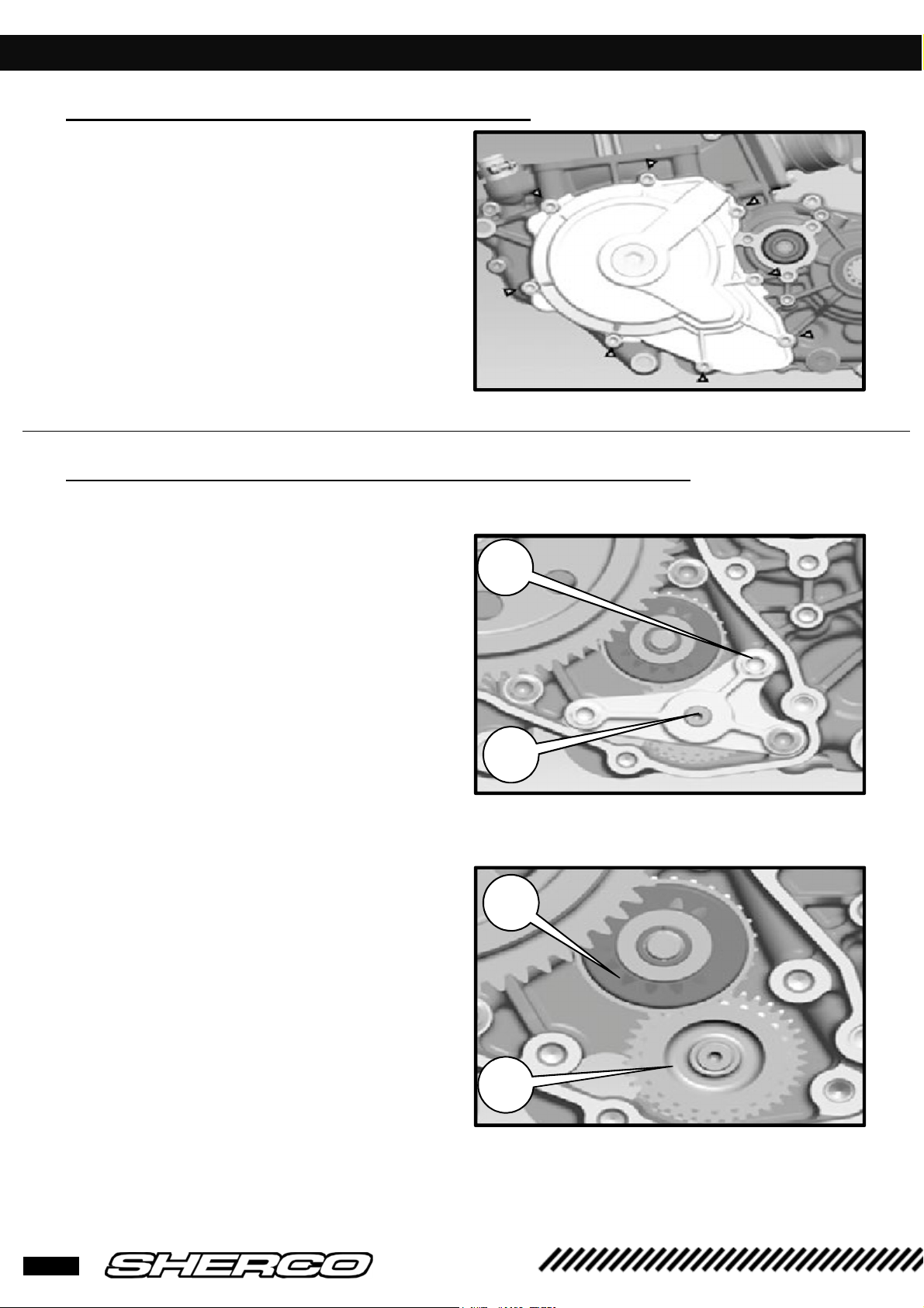
❱❘ Removing the primary transmission
• Remove the screws and extract the ignition
housing with its gasket
❱❘ Removing the torque limiter and the starter drive
• Remove the 3 shoulder screws [1]
• Remove the torque limiter lug [2]
• Remove the starter drive [3]
• Remove the torque limiter [4]
15
250/300 SE
DISMANTLING THE ENGINE
2 1
3
2
4
❱❘ Removing the ignition
•
Hold the flywheel with the 4753 tool
unscrew the shoulder nut.
•
Position the R462 puller
magnetic wheel
[3]
[2]
and extract the
[1]
and
❱❘ Intake pipe and valve box
• Remove the 4 THEP screws
• Remove the pipe, the valve box, and their
respective gasket.
[4]
16
DISMANTLING THE ENGINE
WARNING
WARNING
1 2
3
4
WARNING
•
Separate the half crankcases.
•
Tilt the engine so that the ignition side is
facing you.
•
Remove all the fixing screws.
•
Remove the seal ring and its o-ring from the
gearbox output shaft.
•
Lift the left half crankcase by lightly tapping
the gearbox output shaft with a plastic
mallet to separate it from the other half.
•
Remove the half crankcase and the central
gasket
between the half housings to separate
them should be avoided as much as
possible. You may damage the gasket
Prizing a screwdriver or other tool
surfaces.
Pay attention to the gearbox shafts' set
rings. They can remain stuck inside the
housing
❱❘ Remove the gear selection
• Remove the gearbox lubrication tube ,
• Remove the set ring from the primary shaft
[2]
• Remove the two pin from the shift forks [3]
and push the shift forks to the side to
release tem from the cylinder
• Remove the selection cylinder from its
bearing
• Remove the shift forks
• Remove the primary and secondary shaft
from their bearing together.
When dismantling, take care not to lose
the small rollers
identify which is the corresponding fork
for each roller to facilitate reassembly
[4]
on the fork studs
17
250/300 SE

DISMANTLING THE ENGINE
WARNING
❱❘ Removing the connecting rod assembly
• Remove the connecting rod assembly from its bearing (if necessary by tapping lightly with a plastic mallet
on the end of the crankshaft).
• Clean all parts and check for wear. Replace if necessary.
When completely dismantling the engine, it is best to replace all gaskets, spi seals, o-
rings and even bearings
❱❘ Connecting rod assembly
• If the roller bearing has been changed, the
inner ring which sits against the balance
weight must also be changed.
• Heat the R464 tool to approximately 150°C,
immediately thread it onto the inner ring.
Place the tool correctly on the ring to
encourage heat transfer, then extract the
ring.
• To mount the new ring, heat the tool to
approximately 150°C. Insert the new ring and
thread it immediately onto the connecting rod assembly.
18

CHECKING ENGINE COMPONENTS
A
❱❘ Balance weight, checking the external dimensions
• Use a caliper to measure the external
distance of the balance weights:
External value : 64.3mm +0 / -0.2
❱❘ Radial play of the connecting rod head
• Position the crankshaft on the V and place a
dial gauge [A] against the connecting rod
64.3
head.
• Push B the connecting rod head towards the
gauge, then in the opposite direction.
• The difference between these two
measurements corresponds to the radial
play.
Radial play of the connecting rod head :
Standard : 0.015 mm – 0.025 mm
Tolerable limit : 0.06 mm
If the radial play is greater than the tolerated limit, the crankshaft must be replaced
❱❘ Checking the crankshaft run out
• Measure the lateral play of the connecting
rod head
[A]
;
B
Lateral play of the connecting rod head :
Standard : 0.8 mm - 1 mm
Tolerable limit : 1.25 mm
If the play is greater than the tolerated limit, the
crankshaft must be replaced
19
250/300 SE

CHECKING ENGINE COMPONENTS
WARNING
❱❘ Piston
• If you want to install a used piston, check the following points :
• Skirt : look for any marks (tightening). Light marks can be removed with a soft stone.
• Segment grooves : Segments must not get stuck in their groove. These can be cleaned with an
old segment or emery cloth (400 grit).
• Segment retainers must be tightly held and must not be worn.
• Segments : Check the condition and gap spacing.
❱❘ Gap spacing
• Thread the segment into the cylinder and position it with the piston (about 10 mm from the
top edge of the cylinder).
• Using a spacer, the gap spacing is measured.
Gap spacing :
Standard 0.35-0.45mm ,
Max 0.65mm.
If the gap is greater than indicated, check the condition of the cylinder and the piston. If their
dimensions are within the tolerance range, replace the segment
❱❘ Piston pin check
Piston pin diameter
Standard 17,995-17,998 mm
Tolerable limit 17,962
piston pin hole diameter
Standard : 18.006-18.010mm
Tolerable limit : 18.08
❱❘ Checking the wear condition of the cylinder
• To detect cylinder wear, the bore is measured with a bore comparator at about 10 mm
from the top edge of the cylinder. Measure from both direction to identify any potential
ovality.
Cylinder Cylinder bore Piston
250 66.410-66.420
A
300 72.10-72.020
66.421-66.430
72.021-72.030
B
A
B
20

CHECKING ENGINE COMPONENTS
•
Remove the valve cover
•
Remove the actuator support
•
Remove the stop screw
copper sealing washer
•
Remove the bore circlip with circlip pliers
[29].
•
Remove the valve mechanism assembly
[6].
[10]
[9].
[12].
with the
❱❘ Functional check
•
Clean and descale all the dismantled parts.
•
Check with your fingernail that there are no notches on the exhaust barrels [32] and [35],
visually check their seating in the cylinder.
•
Inspect the axis of rotation of the exhaust valve [33], replace it if there are notches that you can
feel with your fingernail.
•
Test the play in the exhaust barrel bearings [31] and check that there is no hard point over
360°.
•
Systematically change all the gaskets on the top of the engine [28, 7, 26, 4, 5, 11, 15, 9]
before reassembling.
•
To reassemble, follow the disassembly procedure in reverse, paying attention to the following
points.
21
250/300 SE

CHECKING ENGINE COMPONENTS
WARNING
When reassembling the actuator support
[12]
, be careful that the 2 screws are not
the same lengt
•
After reassembly, check the lateral play of
the central valve minimum 0.1 mm
•
Check that the pin stops against the valve
(kidney-shaped contact) when it is 100 %
open
.
•
Check that the pin stops against the valve
(kidney-shaped contact) when it is 100 %
closed
22

CHECKING ENGINE COMPONENTS
WARNING
In the following cases the valve must not reach the stopper during opening and
closing
•
Check the lateral play of all the mechanics
minimum 0.1 mm
23
250/300 SE

CHECKING ENGINE COMPONENTS
WARNING
4X M5X16
4X M5X16
4Nm
M6X20
❱❘ Valve stop learning after cylinder reassembly
After any maintenance operation on the internal parts of the cylinder and/or
after changing the cylinder, the Sherco diagnostic tool's machine learning
application must be run (see p63 diagnostic tool chapter).
❱❘ Valve box intake pipe sleeve
•
Over time the carbon tabs gradually lose
their elasticity, which results in a loss of
power.
•
Replace the worn or damaged box.
•
Check the condition of the intake sleeve,
especially if it is not cracked
24

CHECKING ENGINE COMPONENTS
4
❱❘ Clutch
• Stopper
•
Rod [8] check for wear. Minimum length : 194.7 mm.
•
Springs
[3]
check wear.
[17]
Check their length. Minimum spring length 45 mm. Replace the 6 springs if
necessary.
•
8 clutch plates [14] Minimum thickness 2.68 mm.
•
The 7 smooth disks must be in good condition with a maximum deformation limit of 0.05 mm.
Refer to the 250 SE-R/300 SE-R spare parts catalogue for exploded views
❱❘ Gearbox
•
Apply grease to the shift fork studs and
thread the rings
•
Fix the securing washers
and secondary shaft.
•
Position both the primary and secondary
shafts and push them into their respective
bearings until they stop.
[1]
over them.
[2]
on the primary
•
Identify the direction and location of the
forks on the picture. Fork
[3]
corresponds
to the primary shaft.
25
250/300 SE

CHECKING ENGINE COMPONENTS
WARNING
1
WARNING
WARNING
gearbox shafts must now turn without any
1
A used fork must have its original pinion and its
rollers
•
Attach the forks in the grooves of the sliding
gears and push the barrel into its ball bearing.
•
Oil the fork shafts and thread them into the
forks. Push the forks into their housing in the
housing until they stop
When the forks are attached in the barrel, it is
important to be careful that the rollers do not
fall off the studs
.
The
hard points.
26

REASSEMBLING THE ENGINE
WARNING
Pay attention to the tube indexing, flat section
❱❘ Assembling the half crankcases
•
Assemble the gearbox lubrication tube on the right half crankcase
near oil cap rivet.
• Fit the o-ring onto the gearbox lubrication tube.
• Make sure that the centering rings are in place
on the right half crankcase and that the gearbox
shaft washers are also assembled.
• Lubricate the seals of the left half housing and
put in position.
• Fix the screws and tighten to 10 Nm.
•
Next, lightly tap the crankshaft with a plastic
mallet and check that the shafts turn without
hard points
any
27
250/300 SE

REASSEMBLING THE ENGINE
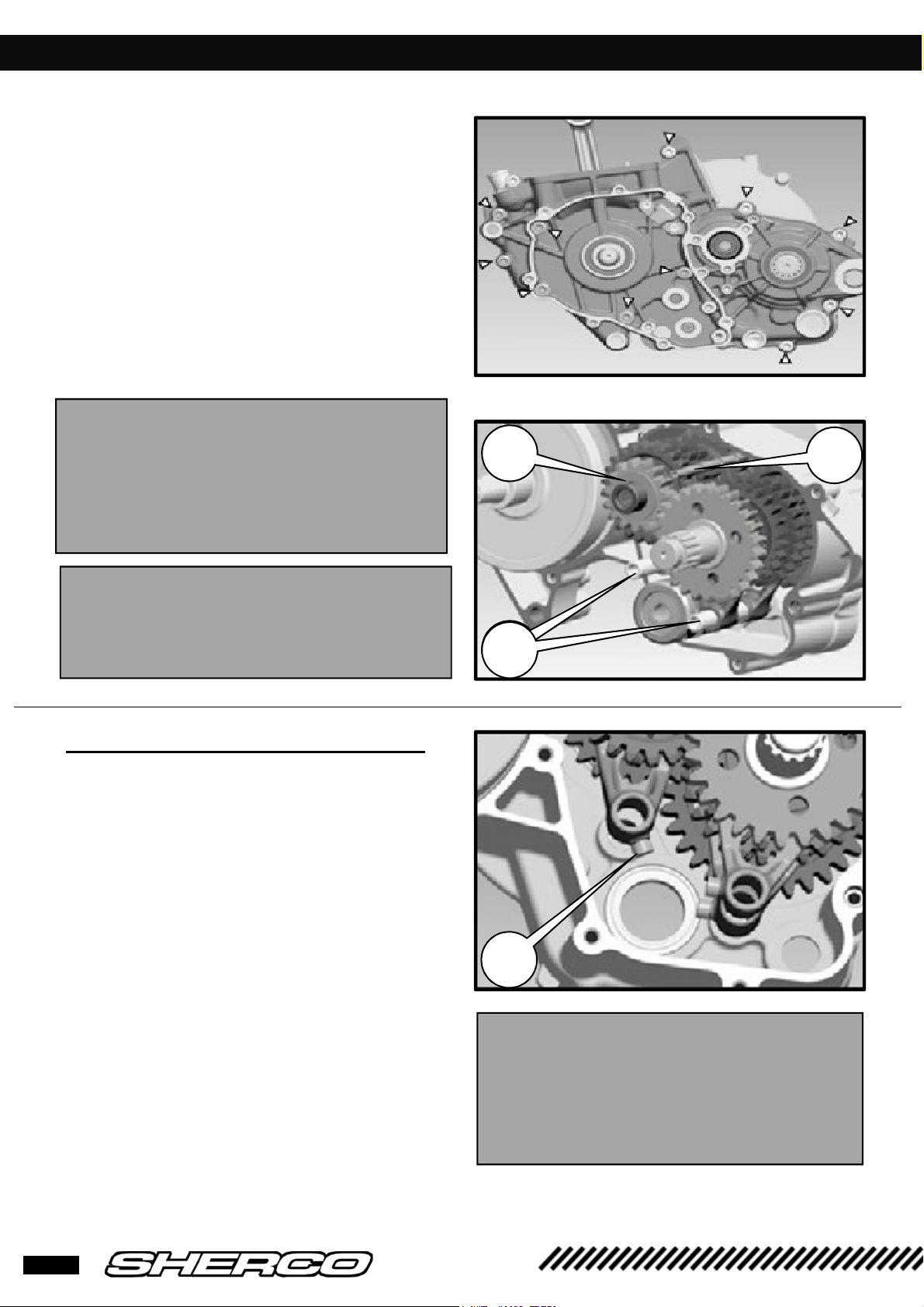
❱❘ Gear selection mechanism
•
Put the spring in the crankcase with the
strand bent upwards.
•
Thread the spacer, the locking pin the
washer, coat the CHC M6X20 screw with
blue threadlock and assemble all parts.
•
Attach the spring to the lever. The other end
of the spring must be pressed against the
housing.
•
Fit the star selector's indexing pin onto the
drum.
•
Pull the lock lever back to position the star
selector.
•
Coat the screw with blue threadlock and
assemble the star selector on the drum
•
Grease the already assembled selection pin
and thread it into the needle bearings
without forgetting the lock washer.
•
When the prong stops against the star
selector push it back so that the shaft can
be lowered completely
•
Check that the return spring strands are
against the pin on each side of the housing.
•
Position the selector and try changing all
the gears. You will have to turn the gearbox
output shaft to change the different gears.
Remove the selector again
28

REASSEMBLING THE ENGINE
2 1
3
❱❘ Primary transmission and clutch
•
Grease the connecting rod assembly seal.
•
Thread the previously oiled o-ring onto the
connecting rod assembly, then fit the steel
spacer with the groove on the same side as
the balance weight.
•
Install the half-moon pin in its housing.
•
Thread the pinion onto the rear of the
crankshaft with the shoulder facing down.
•
Thread the washer
needle cages
[1]
and the two oiled
[2]
onto the primary shaft
•
Fit the clutch housing and its crenellated
washer [3]
•
Coat the threads of the primary shaft with
blue threadlock.
•
Mount the clutch boss on the primary
shaft, coat its nut with red threadlock and a
new safety washer.
•
Employ the 5749 tool and tighten the nut to
100Nm.
•
Remove the tool and brake the nut by
folding the edge of the lock washer.
•
Put blue threadlock on the crankshaft
thread.
•
Assemble the conical washer and nut.
•
Lock the primary gear with the 5206 tool
and tighten the crankshaft pinion nut to
150 Nm using red threadlock.
•
Remove the 5206 tool and check there are
hard points in the primary transmission by
rotating the connecting rod
29
250/300 SE

WARNING
REASSEMBLING THE ENGINE
❱❘ Clutch discs, pressure plate
• Oil the push pin [1] and thread it onto the
primary shaft.
• Before assembly oil the clutch plates.
• Start with clutch plate. The 8 clutch discs
and the 7 smooth discs are alternated.
• Place the pressure plate, springs, cups and
CHC screws.
• Tighten the screws crosswise to 10 Nm
❱❘ Clutch housing
•
Check that the two centering bushing are in
place in the clutch housing.
•
Fit the housing gasket and hold it in place
with a Little grease.
•
Glue the water pump set ring [2] with a little
grease.
•
Position the clutch housing making sure that
the water pump assembly is in place. The
connecting rod assembly must be rotated so
that the water pump pinion can engage the
end of the crankshaft.
•
Fix the THEP M6 screws and tighten to
10Nm except for the M6X12 to 6Nm
Put a new seal on the M6x50 screw, cooling liquid drain screw, and the M6x12 screw.
•
Check that the shafts turn without any hard
points
30

WARNING
REASSEMBLING THE ENGINE
❱❘ Piston and cylinder
•
Oil the parts thoroughly before reassembling.
•
Thread the needle bearing into the small
end, position the piston (the arrow on the top
of the piston in the direction of the exhaust).
•
Position the shaft and the clips with the open
side down.
•
Place the 0.5 mm header gasket.
•
Correctly position the segments, reference
marks facing up.
•
Install the cylinder.
•
Tighten the flange nuts in 2 passes.
•
The 1st to 20 Nm and the 2nd to 35 Nm.
•
Check the squish by measuring the distance
between the piston surface at top dead
center and the cylinder head surface
firstly measure after having
placed a 0.5 mm header
gasket), depending on the
value obtained from the
following squish adjustment
table, adjust with one or more
header gaskets
31
250/300 SE

REASSEMBLING THE ENGINE
❱❘ Squish table
Squish, Standard = 1.7±0.1 mm (Set back of piston = -0.05mm)
Measurement of piston's overrun
or set back (-) (X mm)
Made with a 0.5 mm gasket
X ≤ - 0,25 1,9 mm 0,3 mm 4942
-0,25 < X ≤ - 0,15 1,8 mm 0,4 mm 7238
-0,15 < X ≤ - 0,05 1,7 mm 0,5 mm 3840
-0,05 < X ≤ 0,05 1,6 mm 0,6 mm 4932 + 4942
0,05 < X ≤ 0,15 1,5 mm 0,7 mm 7238 + 4942
0,15 < X ≤ 0,2 1,45 mm 0,75 mm 4943
Squish 1st
measurement
0.5 mm gasket
Thickness of
gasket to have
a 1.7 mm
Squish
Sherco
reference
gasket(s) to be
mounted for
1.7 mm Squish
❱❘ Cylinder head
•
Clean the cylinder gasket and cylinder head surfaces.
•
Put the 2 centering pins on the cylinder.
•
Position the cylinder head.
•
Fit the M8 shouldered screws with new copper washers.
•
Tighten three times crosswise to 25Nm
32

REASSEMBLING THE ENGINE
❱❘ Valve box and intake pipe
•
Place a new valve box gasket.
•
Put the complete valve box in the intake
duct.
•
Install a new intake pipe gasket.
•
Assemble the intake pipe with the 4M6
screws.
•
Install the intake sleeve with its metal collar
❱❘ Gearbox output pinion
•
Oil the o-ring and thread it onto the output
shaft.
•
Thread over the spacer so that the gasket
sits in place.
•
Place the gearbox output pinion, the safety
washer.
•
Put blue threadlock on the thread.
•
Thread the safety washer.
•
Fix the nut to tighten to 150Nm.
•
Unfold the safety washer's tab onto the nut.
❱❘ Starter drive assembly
•
Put the double pinion in the needle cage.
•
Put the starter drive in place.
•
Position the retaining triangle and fix the 3
THEP screws.
•
Lubricate the pinions with grease spray
33
250/300 SE

REASSEMBLING THE ENGINE
WARNING
❱❘ Mounting the ignition and its cover
•
Put the half moon pin in its housing on the crankshaft.
•
Thread the rotor onto the crankshaft.
•
Put blue threadlock on the thread.
•
Using the 5207 tool, put on the nut and tighten to 60Nm.
•
Put the 2 centering sleeves in position.
•
Fit a new gasket and secure the ignition cover
❱❘ Mounting the electric starter
•
Replace the starter's o-ring with a new gasket.
•
Lightly grease the o-ring.
•
Install the starter into the right crankcase.
•
Fix the starter with the 2 THEP screws.
•
Finish by oiling and threading the clutch control rod into the primary shaft.
•
Fit the speed selector with its screw and washer
•
Fit the two drain plugs with a new seal.
The gear box must be filled when the engine is back on its frame ; if not, a
certain amount of oil will escape out the primary shaft.
34

1
2
4
3
SYNERJECT) INJECTION SYSTEM INSTRUCTION MANUAL
INTRODUCTION SYNERJECT SYSTEM
1.1- Synerject system
[1]
Synerject M3C controller : 3459
[3]
High voltage coil : 8308
[2]
Engine actuator : 6933
[4]
Water temperature sensor : 0380
1.2- Description Exxodiag diagnostic Tools référence 4967
Your Sherco 250 SE-R and 300 SE-R is equipped with a Synerject electronic management
system consisting of an M3C controller, an ignition, an engine actuator, a high voltage coil, a
water temperature sensor and a specific electrical harness
35
250/300 SE

SYNERJECT
mail to courrierxxotest.com.
1.3- Diagnostic tool kit contents.
The case consists of a USB to MUX output cable, a MUX peripheral device, a MUX to
motorcycle diagnostic connector cable, an installation CD (or the link below), a user manual
1.4- Installation of the diagnostic tool
In case of problem during the installation please contact EXWOTEST at +33 (0)4 50 02 34 34 or by
A- Installing the software and drivers
• Open the installation CD on your computer
• Run “ sherco_setup”
•
Select the language.
)
INJECTION SYSTEM INSTRUCTION MANUAL
• Click on « Next ».
• Choose the installation folder.
36

SYNERJECT
)
INJECTION SYSTEM INSTRUCTION MANUAL
• Click on « Next ».
• Click on « Install ».
• Installation in progress.
37
250/300 SE

SYNERJECT
•
Check the box « Start the driver installation
• The following window will open. Read the
« I accept the terms of the license agreement »
)
INJECTION SYSTEM INSTRUCTION MANUAL
»
and click on « Finish ».
terms of the license agreement. Check the box
and click on « Install ».
• Installation in progress.
38

SYNERJECT
)
INJECTION SYSTEM INSTRUCTION MANUAL
• The following window will open. Click on
« Finish ».
The installation is complete
.
B- Connect the « MUXDIAG II » cable and its interface to a USB port on your computer
Connect the cable to the diagnostic connector of the motorcycle.
Make sure the « MUXDIAG II » unit is properly powered by checking the LED:
• Solid blue
• Flashing blue
• Blue off
• Solid green:
• Flashing green (slow):
• Flashing green (fast):
• Green off:
• Solid red
• All LEDs OFF:
: PC connection properly established.
: communication with PC in progress.
: no connection to the PC, or device in standby; it can also indicate a problem with the USB connector.
firmware issue.
no firmware.
: correct power supply to the card.
the outlet is not powered on, or is off or USB in on standby mode.
firmware correctly run.
communication with PC in progress.
39
250/300 SE

SYNERJECT
PRESENTATION OF THE SOFWARE
2.1- Connection with Keyless system
Sherco had a Keyless system on its motorcycles which allows the bike to switch on without
any key and switch off automatically after 30secondes of non-use.
This last point blocks the diagnostic, this is why it is necessary to follow the steps down
below before doing it.
1.
Remove the plug
part of the bike).
2
)
INJECTION SYSTEM INSTRUCTION MANUAL
(1)
from the connector
1
(2)
(located on the rear sub frame – on the right
2
1
2.
Take the shunt (3) (reference 6267) and connect the plug (1) into it.
3
3.
You can now do the diagnostic by following the next explanations.
40

SYNERJECT
Update and
)
INJECTION SYSTEM INSTRUCTION MANUAL
Information:
To set up the connection with the motorcycle, the motorcycle must be switched on (On). To
navigate through the different menus, the USB cable with the «MUXDIAG II» device only may be
connected to the computer.
Run the software using the icon
The following menu will come up
:
update, proxy
Diagnostics menu
(diagnostic, map
updates,etc.)
Setup menu
(language selection, units,
etc.)
41
250/300 SE

SYNERJECT) INJECTION SYSTEM INSTRUCTION MANUAL
2.2-
Software settings: configuration menu
In this menu, you can modify:
• The diagnostic plug. You can refresh the list by hitting the button.
The number must match the number of the « MUXDIAG II »
device.
• The languages available in the software: English, French, Spanish, Portuguese, German, Italian (the
installation CD provided may not include all languages). Update the software-> page 53).
• Set the unit system.
• Click to return to the home screen.
• Click to save the changes.
42

SYNERJECT
2.3- Update menu and synchronization
)
INJECTION SYSTEM INSTRUCTION MANUAL
A- In this menu, you can update the diagnostic software tool
• To determine whether an update is available,
check that you have an Internet connection,
and then click on the following icon
• If an update is available, the following
window will come up:
• If no update is available, the following
message will come up :
43
250/300 SE

SYNERJECT
•
Click on to start downloading the
update.
•
The following message will come up
•
Click on to start installation
•
Resume the installation process -> page 41. It is not necessary to restart the installation of the drivers
)
INJECTION SYSTEM INSTRUCTION MANUAL
B- Configuration of Internet access parameters
It may be necessary to set up a proxy server to access the Internet
• Click on
• Fill in the following settings if necessary.
• Click on to save your changes.
.
44

SYNERJECT
)
INJECTION SYSTEM INSTRUCTION MANUAL
3 Using
Diagnostic menu and injection mapping update
General
• Click on « Sherco ».
• Click on « M3C ».
the software
• You get the following menu
:
3.1 Identification
You can check the identification of the following (serial number, hours of operation,
calibration number)
45
250/300 SE

SYNERJECT
A. Parameter measurements
)
INJECTION SYSTEM INSTRUCTION MANUAL
General parameters
B. Engine information
Displayed below are the main system values
:
3.2 Reading the default codes
When you click on "read default codes” the system starts checking.
• If no default appears exit the menu by clicking on this icon:
46

SYNERJECT
•
If a default appears:
)
INJECTION SYSTEM INSTRUCTION MANUAL
• You can get the details of the default by clicking on the default display :
• Record the defaults and exit the menu by clicking on this icon
Note:
1-
Transient default/permanent default: a transient default becomes permanent after a
certain number of engine cycles of the following components (injector, fuel pump, etc). For a
permanent default to disappear it takes 40 cycles without the engine default reappearing.
2-
Fan Default : If there is no fan installed on the bike, there will always be a rise in the fan
default code (P0485)
47
250/300 SE

SYNERJECT
3.3 Erasing default codes
1-
If a default appears: go to the menu « Erasing default codes »
Click this icon in order to erase all of the default codes
)
INJECTION SYSTEM INSTRUCTION MANUAL
The following screen will appear:
Confirm by clicking on this icon
48

SYNERJECT
Return to the menu « reading default codes »
Check and make sure that the defaults are the same as before. Check/replace the
defective parts. Check all of the connections.
3.4 Test the actuators
)
INJECTION SYSTEM INSTRUCTION MANUAL
In addition to reading default codes you can also check some of the system components
1-
Ignition coil
When you launch the ignition coil test, the following message will appear
:
:
49
250/300 SE

SYNERJECT) INJECTION SYSTEM INSTRUCTION MANUAL
The system is not able to detect an ignition coil failure with the engine stopped. The test results will be
the same if the coil is faulty or not. Therefore, when testing the ignition coil make sure that the
engine makes the correct sound for a properly functioning ignition coil.
2-
Fan
For the fan perform a standard test. If there is a default it twill appear as a classic default
3-
Exhaust valve learning
.
50

SYNERJECT
3.5 Updating the ECU
By using the diagnostic tool it is possible to make updates to the injection mapping (calibration).
An example would be the fitting of a racing silencer or there is an update from the factory.
These files will be freely available on sherconetwork:
)
INJECTION SYSTEM INSTRUCTION MANUAL
You must pay attention to the model, the displacement, the type of silencer, etc
In case of doubt, contact technical support.
1. Download the desired update (file.mot)
ShercoNetworkInformationTechnical informationInjection Map
.
51
2-
Power up the motorcycle
3-
Click on the computer update
250/300 SE

SYNERJECT
Confirm by clicking on this icon
Select the calibration file (.mot) that was previously downloaded and click open.
4. The file is being downloaded
)
INJECTION SYSTEM INSTRUCTION MANUAL
WARNING
DO NOT TURN OFF THE MOTORCYCLE DURING THE DOWNLOAD OPERATION (FLASH)
DO NOT ABRUPTLY STOP THE FLASH DOWNLOAD PROCESS THERE IS A RISK
OF IRREPAIRABLE DAMAGE TO THE COMPUTER
5. At the end of the download the fuel pump will start and the following message will appear :
INFORMATION : Download was successful
Confirm by clicking on this icon
6. Check to make sure that the correct calibration file was allocated by clicking on
« Identification »
Check to make sure that the file name matches the file that was download
52

SYNERJECT) INJECTION SYSTEM INSTRUCTION MANUAL
Information:
update.
7.
8.
9.
10.
3.6 Screen printing function
If you are communicating with technical support and need help identifying potential
problems you can perform a screen print operation by pressing F10 on your keyboard.
This will allow you to attach these files to your inquiry.
The "identification" screen contains all of the important information about the motorcycle
(serial number of the bike, number of hours of operation, calibration, etc)
the information on serial number and operating hours are not reset during a calibration
Put back the “shunt” on the connector in the air filter box to switch back on “keyless”
mode.
-The ECU power latch will proceed during 20 s.
-Wait 30 s until the ECU stop before starting the bike.
Start the bike, stop it and wait 30 s before to restart the bike11-Switch on the bike and
verify that the parameters of the motor are normal
53
250/300 SE

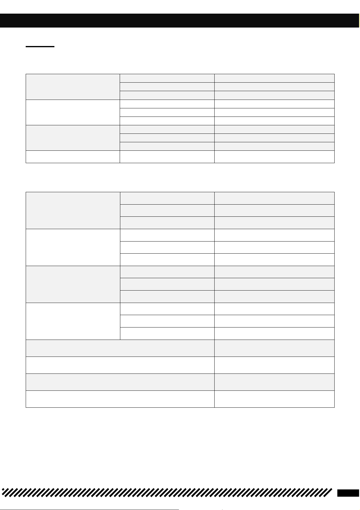
TORQUES TABLE
Standard tightening torque
Threadlock
M5 7 Nm
M6 10 Nm
M8 25 Nm
Chassis tightening torque
Threadlock
Rear wheel nut 100 Nm
Rear cradle fixing screw 24 Nm
Front wheel nut 40 Nm
Fork end pinch screw 15 Nm
Brake pad pin screw 8 Nm
Pinch screw for lower fork tees WP 12 Nm KYB15
Nm
Pinch screw for upper fork tees WP 17 Nm KYB 17
Nm
Engine screw 60 Nm
Swivel-arm screw 100 Nm
•
•
Head-frame screw 24 Nm
Engine torque
Threadlock
RPM sensor screw 8 Nm
Coolant drain screw 10 Nm
Oil level screw 6 Nm
Clutch slave cylinder screw 9 Nm
Cylinder head crosswise tightening torque
25 Nm
Crankshaft handhold plug 8 Nm
Clutch pressure screw 10 Nm
Water pump housing screw 10 Nm
Ignition flywheel nut 60 Nm
Clutch boss nut 100 Nm
Primary transmission pinion nut 150 Nm
Ignition housing screw 10 Nm
Central crankcase screws 10 Nm
Barrel screw 10 Nm
•
•
•
•
•
Starter triangle screw 10 Nm
Starter screw 10 Nm
Cylinder nut Pass No. 1 20 Nm
Pass No. 2 35 Nm
Gearbox output pinion nut 150 Nm
•
54

CARBURETOR ADJUSTEMENT TABLE
to
45 42 42 40 38 35
1 501 m
N1EG
N1EG
N1EG
N1EH
N1EH
N1EI
3 3 2 2 2 2
165 165 162 160 160 158
to
45 45 42 42 40 38
751 m
N1EF
N1EG
N1EG
N1EG
N1EH
N1EH
3 3 3 2 2 2
168 165 165 162 160 158
to
48 45 45 42 42 40
301 m
N1EF
N1EF
N1EG
N1EG
N1EG
N1EH
4 3 3 3 2 2
170 168 165 162 162 160
to
50 48 45 45 42 42
0 m
N1EE
N1EF
N1EF
N1EG
N1EG
N1EG
4 4 3 3 3 2
172 170 168 165 165 162
❱❘ SE 250-Carburetor adjustments table
Sea level Temperature -20°C
-7°C
3.000 m Air screw 1T1/4 1T3/4 1T3/4 2T1/4 2T1/4
to
2.301 m
2 300 m Air screw 1T1/4 1T1/4 1T3/4 1T3/4 2T1/4 2T1/4
1 500 m Air screw 1T 1T1/4 1T1/4 1T3/4 1T3/4 2T1/4
adjustment
Idle jet
Needle
Needle position
Main jet
adjustment
Idle jet
Needle
Needle position
Main jet
42 42 40 38 35
N1EG N1EG N1EH N1EH N1EI
3
165 162 160 160 158
-6°C
5°C
2
6°C
15°C
2
16°C
24°C
2
25°C
36°C
2
37°C
49°C
adjustment
Idle jet
750 m Air screw 1T 1T 1T1/4 1T1/4 1T3/4 1T3/4
300 m Air screw 1T 1T 1T 1T/4 1T1/4 1T3/4
Needle
Needle position
Main jet
adjustment
Idle jet
Needle
Needle position
Main jet
adjustment
Idle jet
Needle
55
Needle position
Main jet
250/300 SE

CABURETOR ADJUSTEMENT TABLE
❱❘ SE 300-Carburetor adjustments table
Sea level Temperature -20°C
…
-7°C
3.000 m Air screw
to
2.301 m
2 300 m Air screw
to
1 501 m
adjustment
Idle jet
Needle
Needle position
Main jet
adjustment
Idle jet
Needle
Needle position
Main jet
1T1/2 1T/1/2 2T 2T 2T1/2 3T
42
42 42 42 42 42
N8RE
3 2 2 1 1 1
172 172 170 168 165 165
1T 1T1/2 1T 1/2 2T 2T 2T1/2
42
N8RD
3 3 3 2 2 1
175 172 172 170 168 165
-6°C
… 5°C
N8RE
42 42 42 42 42
N8RE
6°C …
15°C
N8RF
N8RE
16°C
…
24°C
N8RF
N8RF
25°C
…
36°C
N8RG
N8RF
37°C
…
49°C
N8RH
N8RG
1 500 m Air screw
to
751 m
750 m Air screw
to
301 m
300 m Air screw
to
0 m
adjustment
Idle jet
Needle
Needle position
Main jet
adjustment
Idle jet
Needle
Needle position
Main jet
adjustment
Idle jet
Needle
Needle position
1T 1T 1T1/2 1T1/2 2T 2T
45 42 42 42 42 42
N8RC
N8RC
N8RB
N8RD
3 3 3 3 2 1
178 175 172 172 170 168
1T 1T 1T 1T1/2 1T/12 2T
48
45 42 42 42 42
N8RC
4 3 3 3 3 2
180 178 175 172 172 170
1/2T 1T 1T 1T 1T1/2 1T 1/2
48 45 45 42 42 42
N8RC
4 4 3 3 3 3
N8RE
N8RD
N8RC
N8RE
N8RE
N8RD
N8RF
N8RE
N8RE
N8RF
N8RF
N8RE
Main jet
182 180 178 175 172 172
56

CHECKING THE LOAD CIRCUIT
❱❘ Static control value
For this control please make sure the bike is off
•
Battery voltage > 12.5V.
•
Resistance values of stator windings : Measurement of the resistance between each winding.
Y1-Y2 0.44Ω±20
Y2-Y3
Y1-Y3
% (at
20°C)
❱❘ Dynamic control values
•
Voltage regulator :
AC (calibrated 200V AC) When idling
22V ±2V
At 6000 rpm min : 77V±3V DC
On regulator output (Calibrated 20V DC) At 4000 rpm
: 14.6V + Red/White, - Green
•
Alternator :
57
250/300 SE

T° SENSOR, ENGINE RPM SENSOR, HIGH VOLTAGE COIL
•
Water temperature sensor resistance (on cylinder head)
TEMP (°C) RESIST (K Ω)
-40
100.950
-30
53.100
-20
29.121
-10
16.599
0
9.750
+10 5.970
+20 3.747
+25 3.000
+30 2.547
+40 1.598
+50 1.150
+60 0.746
+70 0.565
+80 0.377
+90 0.275
+100 0.204
+110 0.153
+125 0.102
•
Pick UP sensor resistance (RPM sensor) : Red ~
Green 100 Ω±20 % (at 20°C).
•
High voltage coil
•
Primary coil 0.75 Ω±10 % (at 25 ± 2.5°C)
58

WIRING DIAGRAM
❱❘ Main harness
59
250/300 SE

WIRING DIAGRAM
❱❘ Standard lights harness
60

WIRING DIAGRAM
❱❘ Racing lights harness
61
250/300 SE

WIRING DIAGRAM
❱❘ Accessories harness
62

 Loading...