

SHERCO 2015 450 SEF-R Workshop Manual
MANUEL D’ATELIER I WORKSHOP MANUAL I MANUAL DE TALLER
450 SEf-R

FOREWORD .................................................................................................................................................................................................... 4
ENGINE TOOLS LIST 450 SEF-R.....................................................................................................................................................................5
TECHNICAL SPECIFICATIONS ........................................................................................................................................................................ 6
• ENGINE ......................................................................................................................................................................................................................... 6
• CHASSIS ....................................................................................................................................................................................................................... 7
FACTORY SETTINGS ......................................................................................................................................................................................8
• FORK ............................................................................................................................................................................................................................ 8
• SHOCK ABSORBER ........................................................................................................................................................................................................ 9
OPERATIONS REQUIRING THE REMOVAL, OR NOT, OF THE ENGINE ............................................................................................................ 10
REMOVING/INSTALLING THE ENGINE ..........................................................................................................................................................11
• REMOVING THE ENGINE .............................................................................................................................................................................................. 11
• INSTALLING THE ENGINE IN THE FRAME ..................................................................................................................................................................... 12
REMOVING THE ENGINE .............................................................................................................................................................................. 13
• PREPARATION ............................................................................................................................................................................................................. 13
• REMOVING THE CYLINDER HEAD COVER ..................................................................................................................................................................... 13
• POSITIONING THE ENGINE AT TOP DEAD CENTER ........................................................................................................................................................ 13
• REMOVING THE CAMSHAFT ........................................................................................................................................................................................14
• REMOVING THE DISTRIBUTION TENSIONER ................................................................................................................................................................ 14
• REMOVING THE DRIVE CHAIN ...................................................................................................................................................................................... 14
• REMOVING THE CYLINDER HEAD ................................................................................................................................................................................. 15
• REMOVING THE CYLINDER ..........................................................................................................................................................................................15
• REMOVING THE PISTON ..............................................................................................................................................................................................15
• REMOVING THE IGNITION COVER .................................................................................................................................................................................15
• REPLACING THE STATOR AND THE ENGINE SPEED SENSOR......................................................................................................................................... 16
• REMOVING THE ROTOR ............................................................................................................................................................................................... 16
• REMOVING THE DRIVE CHAIN ...................................................................................................................................................................................... 16
• REMOVING THE ELECTRIC STARTER ............................................................................................................................................................................ 16
• REMOVING THE CLUTCH .............................................................................................................................................................................................17
• REMOVING THE WATER PUMP HOUSING ...................................................................................................................................................................... 17
• REMOVING THE CLUTCH HOUSING .............................................................................................................................................................................. 17
• REMOVINGTHE WATER PUMP OILSEAL AND THE BEARING SEAL ..................................................................................................................................18
• REMOVING THE CLUTCH BELLHOUSING ......................................................................................................................................................................18
• REMOVNG THE FREEWHEEL SPROCKET ...................................................................................................................................................................... 19
• REMOVING THE OIL PUMP ........................................................................................................................................................................................... 19
• CHANGING THE OIL PUMP ........................................................................................................................................................................................... 19
• REMOVING THE INDEX SHIM .......................................................................................................................................................................................19
• SEPARATING THE CENTRAL CRANKCASES .................................................................................................................................................................. 20
• REMOVING THEGEARBOX ............................................................................................................................................................................................ 20
• REMOVING THE CRANKSHAFT ..................................................................................................................................................................................... 20
2
450 SEF-R

SUMMARY
CHECKING INDIVIDUAL PARTS ................................................................................................................................................................... 21
• CHECKING THE CENTRAL CRANKCASES ..................................................................................................................................................................... 21
• CHECKING THE LEFT CRANKCASE ............................................................................................................................................................................... 21
• CHECKING THE RIGHT CRANKCASE ............................................................................................................................................................................. 21
• CHECKING THE FREEWHEEL BEARING ......................................................................................................................................................................... 22
• CHANGING THE CRANKSHAFT BEARINGS .................................................................................................................................................................... 22
• CHECKING THE CRANKSHAFT .....................................................................................................................................................................................23
• CHECKING THE GEARBOX ............................................................................................................................................................................................ 24
• CHECKING THE CLUTCH .............................................................................................................................................................................................. 24
• CHECKING THE TOP ENGINE ........................................................................................................................................................................................ 25
• CHECKING THE CYLINDER HEAD .................................................................................................................................................................................28
• CHECKING THE DISTRIBUTION..................................................................................................................................................................................... 28
ENGINE ASSEMBLY ...................................................................................................................................................................................... 29
• INSTALLING THE CENTRAL CRANKCASES ...................................................................................................................................................................29
• INSTALLING THE CLUTCH HOUSING .............................................................................................................................................................................31
• INSTALLING THE WATER PUMP HOUSING .................................................................................................................................................................... 31
• INSTALLING THE CLUTCH ............................................................................................................................................................................................32
• INSTALLING THE ELECTRIC STARTER .......................................................................................................................................................................... 32
• SETTING THE PISTON RINGS ....................................................................................................................................................................................... 33
• INSTALLING THE PISTON .............................................................................................................................................................................................33
• INSTALLING THE CYLINDER .........................................................................................................................................................................................34
• INSTALLING THE CYLINDER HEAD ............................................................................................................................................................................... 34
• INSTALLING THE DRIVE CHAIN ....................................................................................................................................................................................35
• INSTALLING THE ROTOR ............................................................................................................................................................................................. 35
• INSTALLING THE CAMSHAFT AND SETTING THE VALVE TIMING .................................................................................................................................... 36
• CHECKING VALVE CLEARANCE ..................................................................................................................................................................................... 36
• COMPLETING THE ENGINE ASSEMBLY ......................................................................................................................................................................... 37
• INSTALLING THE IGNITION COVER ............................................................................................................................................................................... 37
ENGLISH
TIGHTENING TORQUE CHART ......................................................................................................................................................................38
CLEANING THE THROTTLE BODY ................................................................................................................................................................. 40
• EQUIPMENT ................................................................................................................................................................................................................ 40
• REMOVING THE THROTTLE BODY ................................................................................................................................................................................ 40
• CLEANING THE THROTTLE BODY ................................................................................................................................................................................. 42
• INSTALLING THE THROTTLE BODY...............................................................................................................................................................................42
CHANGING THE TPS (THROTTLE POSITION SENSOR) .................................................................................................................................43
INJECTION DIAGNOSTIC TOOL SYNERJECT ................................................................................................................................................ 44
• 1- PRESENTATION OF THE SYNERJECT INJECTION SYSTEM ........................................................................................................................................ 44
• 2- SOFTWARE OVERVIEW ............................................................................................................................................................................................50
• 3- USING THE SOFTWARE ........................................................................................................................................................................................... 54
CHECKING THE CHARGING CIRCUIT ............................................................................................................................................................ 67
WIRING DIAGRAM ....................................................................................................................................................................................... 69
3

This manual is intended for qualified mechanics working in a properly equipped workshop. Performing
the different operations requires sound knowledge of mechanics and SHERCO tools specific to 450 SEF-R
engines.
4
450 SEF-R
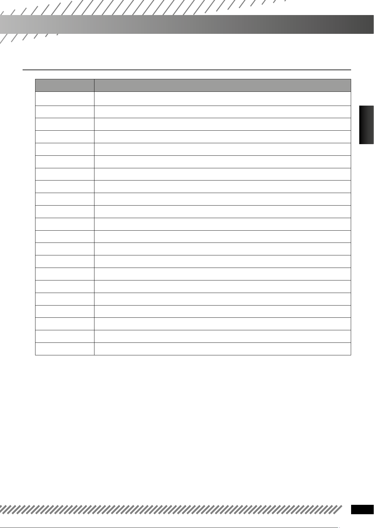
Tools List for 450 SEF-R Engine
❱❘ 450 SEF-R
Tool reference Description
1819 Top dead center timing screw
5749 Clutch removal tool ADLER
4753 Fret-type ignition unit
1822 Water pump bearing axis tool
1968 Water pump oil seal tool
R455 Engine support
5593 Primary drive locking tool
5774 Piston support
R462 Flywheel puller
R464 Crankshaft ring extractor
R450 Oil seal selector
R472 Applying tool for oil seal selector
5773 Special 450 spark plug wrench
5028 PUSH-IN TOOL WP Ø48
4967 Synerject injection diagnostic tool
FRANÇAIS
ENGLISH
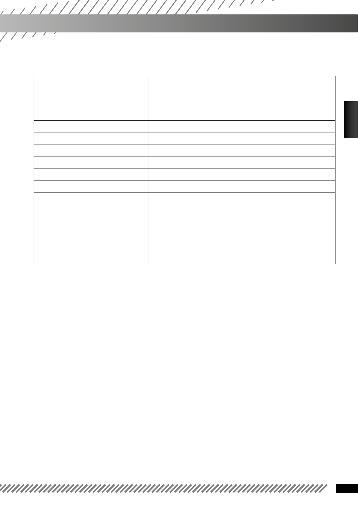
5132 Adjustable hook spanner wrench WP Ø48
5029 Joint guide tool WP Ø48
5030 Bottle-type leveling tool WP
5031 Pipe vise clamp WP 48/60
R453 Selector shaft bearing assembly tool
R444 Oil seal selector
5

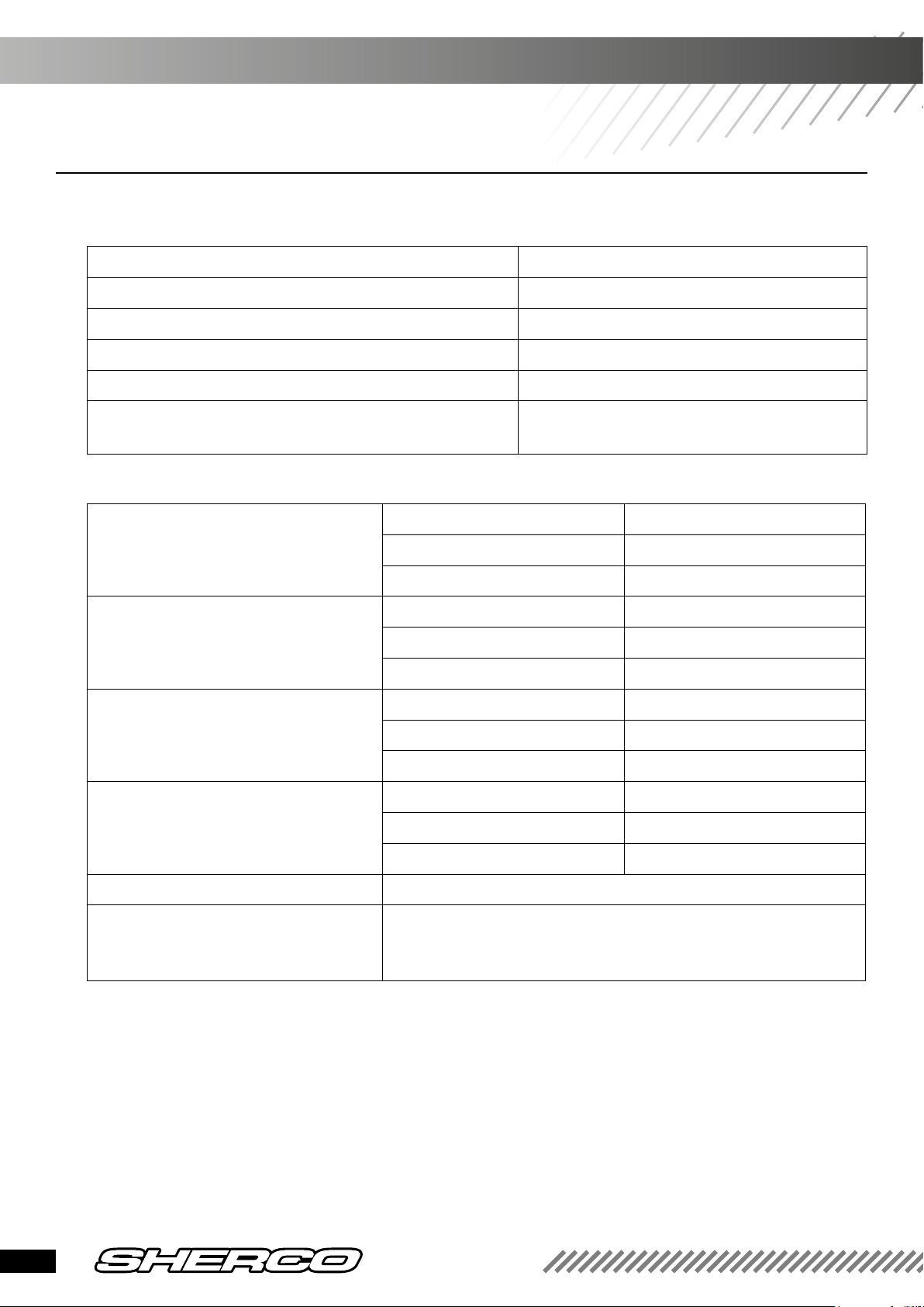
❱❘ ENGINE
Type Single cylinder 4 stroke liquid cooled
Displacement 449.4 cc
Bore / Stroke
Compression ratio 11.84: 1
Unleaded gasoline with an octane rating of at least 95
Distribution 4-valve, double overhead camshaft, chain drive
Intake valve diameter 38 mm
Exhaust valve diameter 30.5
Intake valve cold clearance 0.15-0.2 mm
Exhaust valve cold clearance 0.2-0.25 mm
Crankshaft bearings 2 roller bearings
Piston forged aluminum
Lubrication full pressure lubrication with 2 trochoid pumps
95/63.4 mm
Motor oil 1 liter SAE 10W40
Primary drive 25 : 75
Gearbox
First gear
Second gear
Third gear
Fourth gear
Fifth gear
Sixth gear
Final drive 14 X 49
Clutch multi disc clutch in oil bath, hydraulically operated
Start-up/battery Electric 12V 4Ah
Electronic injection Synerject
6 speed
13 : 32
16 : 29
19 : 27
21 : 24
23 : 22
25 : 21
6
450 SEF-R
TechnicalSpecications
❱❘ Chassis
Frame Semi-perimeter Cr Mo steel with aluminum subframe
Fork SACHS USD Gold Series Ø 48mm (standard) & WP USD Ø 48mm
Semi-perimeter Cr Mo steel with aluminum subframe
(racing)
Rear suspension WP Suspension with separate cylinder
Travel front/rear 300/300 mm
Front brake Disc Ø 270 mm (standard), Ø 256 mm (racing)
Rear brake Disc Ø 220 mm
Disc brakes Wear limit: 2.7 mm front and 3.6 mm rear
Front tire 90/90-21’’
Rear tire 140/80-18’’
Pressure off-road front/rear 0.9 bar
Fuel tank capacity 8.5 l with 1 l reserve
Steering angle 27.3°
Wheelbase 1480mm
Weight 120 kg
ENGLISH
7
❱❘ FoRK
Original settings - Fork SACHS USD Gold Series Ø48 mm
Compression 12 clicks back
Rebound 12 clicks back
Spring stiffness 4.5 N/mm
Type of oil SAE 5
Quantity of oil per fork leg 600 cm
3
Oil level measurement (fork compressed and spring removed) from the top of the fork tube
Original settings - Fork WP Suspension USD Ø48mm
Compression Comfort 21 clicks back
Standard 14 clicks back
Sport 9 clicks back
Rebound Comfort 19 clicks back
Standard 14 clicks back
Sport 11 clicks back
Preload Comfort 0 turn
Standard 2 turns
Sport 4 turns
Spring stiffness Rider weight: 65-75 kg 4.2N/mm
Rider weight: 75-85kg 4.4 N/mm (original)
Rider weight: 85-95kg 4.6N/mm
130mm
Type of oil SAE 4
Oil level measurement (fork compressed
and spring removed) from the top of the
fork tube
8
450 SEF-R
110mm
FACTORY SETTINGS
❱❘ Shock absorber
Factory Settings - WP suspension shock absorber
Low-speed compression Comfort 17 clicks back
Standard 12 clicks back
Sport 9 clicks back
High-speed compression Comfort 2 turns back
Standard 1.5 turns back
Sport 1 turn back
Rebound Comfort 16 clicks back
Standard 14 clicks back
Sport 12 clicks back
Spring stiffness Rider weight: 65-75 kg 51N/mm
Rider weight: 75-85 kg 54N/mm (original)
Rider weight: 85-95 kg 57N/mm
ENGLISH
9
Operations requiring
the removal of the engine
Operations not requiring
the removal of the engine
Crankshaft (including crankshaft
repair kit)
Complete transmission •
Crankshaft bearing •
Gearbox bearing •
Piston •
Cylinder •
Cylinder head •
Distribution •
Ignition •
Starter gears •
Freewheel •
Complete clutch •
Water pump •
Oil pump •
•
Gear selector set •
10
450 SEF-R

removing/installing the engine
❱❘ Removing the engine
WARNING
To remove the engine, remove the swing arm pivot axis, which allows you to remove the whole rear wheel / swing arm set. In
order to prevent the bike from tipping over, hold the frame using a jack.
• Empty (see the User Manual)
- The engine oil
- The coolant.
• Place the motorcycle on a stool.
• Remove the saddle.
• Disconnect the battery (see user manual).
• Remove the tank along with its vents (refer to the user manual).
• Disconnect the entire harness connected to the engine
(starter case, TPS, water temperature sensor, pencil coil and injector).
• Remove the springs of the exhaust pipe in order to remove it.
• Remove the pencil coil
• Remove the throttle body.
• Remove the chain guard.
• Remove the secondary transmission line (quick release).
• Remove the clutch receiver.
ENGLISH
WARNING
When the clutch receiver is removed, the piston is no longer supported. Hold the piston with a plastic clamp.
• Remove the water radiator hoses connected to the engine.
• Remove the left radiator.
• Remove the cylinder head frame mounting brackets.
• Remove the frame guards on both the right and left sides of the bike.
• Unscrew the swing arm pivot.
• Loosen the other two engine axes
• Unscrew the swing arm pivot and pull the swing arm slightly backward.
• Remove the engine axes.
• Remove the engine through the left side by pivoting it.
NOTE :
You should need some help to perform this operation, as the weight is considerable. Make sure you do not
damage the engine mounting brackets on the frame.
11

❱❘ INSTALLING THE ENGINE IN THE FRAME
• Position the motor within the frame.
• Position the swing arm.
• Set the engine axes.
• Tighten the motor axes to 40 Nm.
• Tighten the swing arm pivot to 100 Nm.
• Set the frame guards and secure them with clamps.
• Put the right and left cylinder head supports. Put red thread lock and tighten to 25 Nm.
• Fit the left radiator and tighten to 10 Nm.
• Place the cooling hoses
• Make sure the engine is clean and place back the clutch receiver. Tighten to 10 Nm.
• Place the secondary chain and adjust the tension (see procedure on the user manual).
• Put the chain guard.
• Put the throttle body.
• Put the pencil coil.
• Put the exhaust pipe and secure it to the cylinder with its two springs.
• Reconnect the entire harness connected to the engine
(starter case, TPS, water temperature sensor, pencil coil and injector).
• Reinstall the tank along with its vents (refer to the user manual).
• Reconnect the battery (refer to the user manual).
WARNING
Before reconnecting, check that the ignition key (SEF 450 standard) or the switch (450 SEF / R racing) is in the «OFF» position.
• Place back the saddle.
• Fill coolant and engine oil (refer to the user manual).
12
450 SEF-R
REMOVING THE ENGINE
❱❘ PrEparation
• Place the engine on the R455 engine support tool.
• Drain the engine oil (see user manual).
• Make sure to be in a clean environment before
starting the dismantling of the engine.
• Remove the output shaft pinion.
ENGLISH
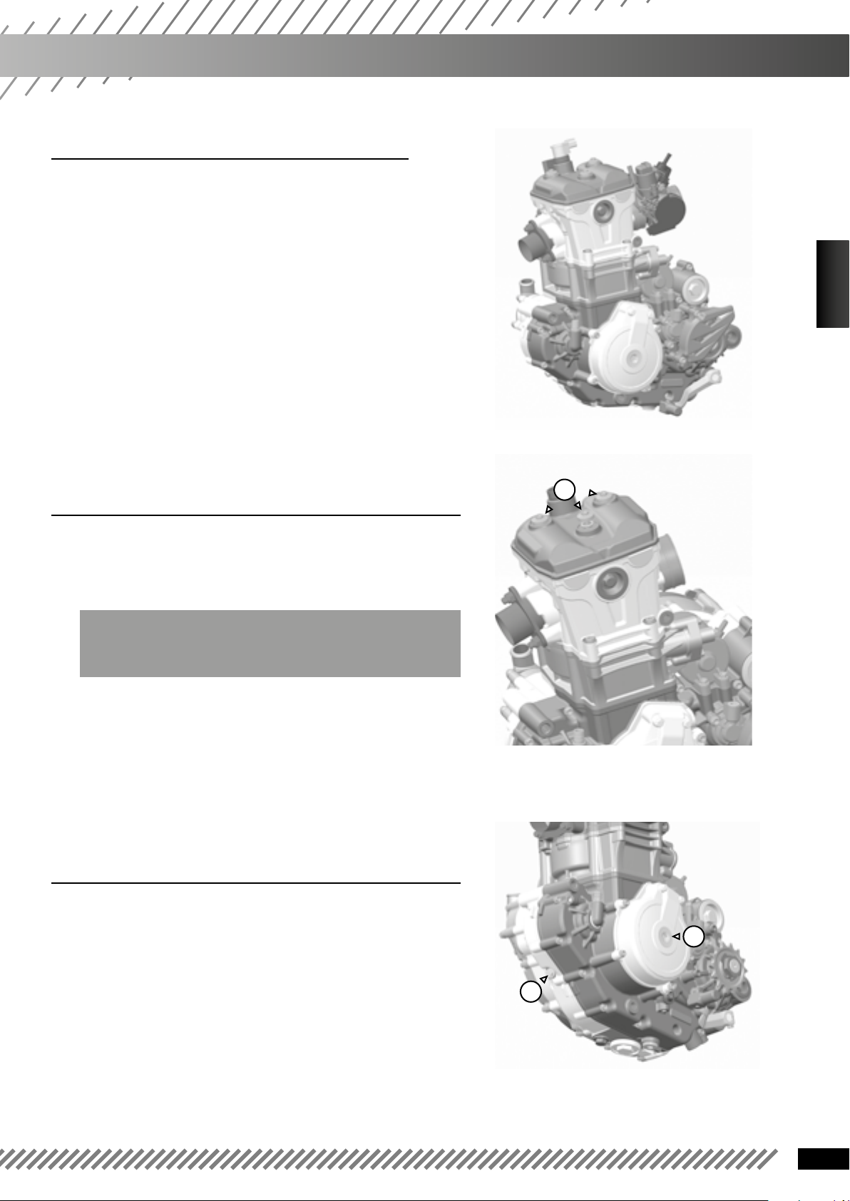
❱❘ Removing the cylinder head cover
• Remove the spark plug with the special spark plug tool 5773.
• Unscrew the 3 screws (1) and remove the cylinder head
cover.
WARNING
The screws have an O-ring.
• Remove the cylinder head cover gasket.
❱❘ Set the engine at top dead center
1
• Remove the ignition cover plug (1).
• Remove the timing control plug (2).
• Rotate the motor counterclockwise in order to align
the center of the hole of the crankshaft with that of the
crankshaft timing control, set the top dead center timing
tool on (2) (Ref. 1819).
1
2
13
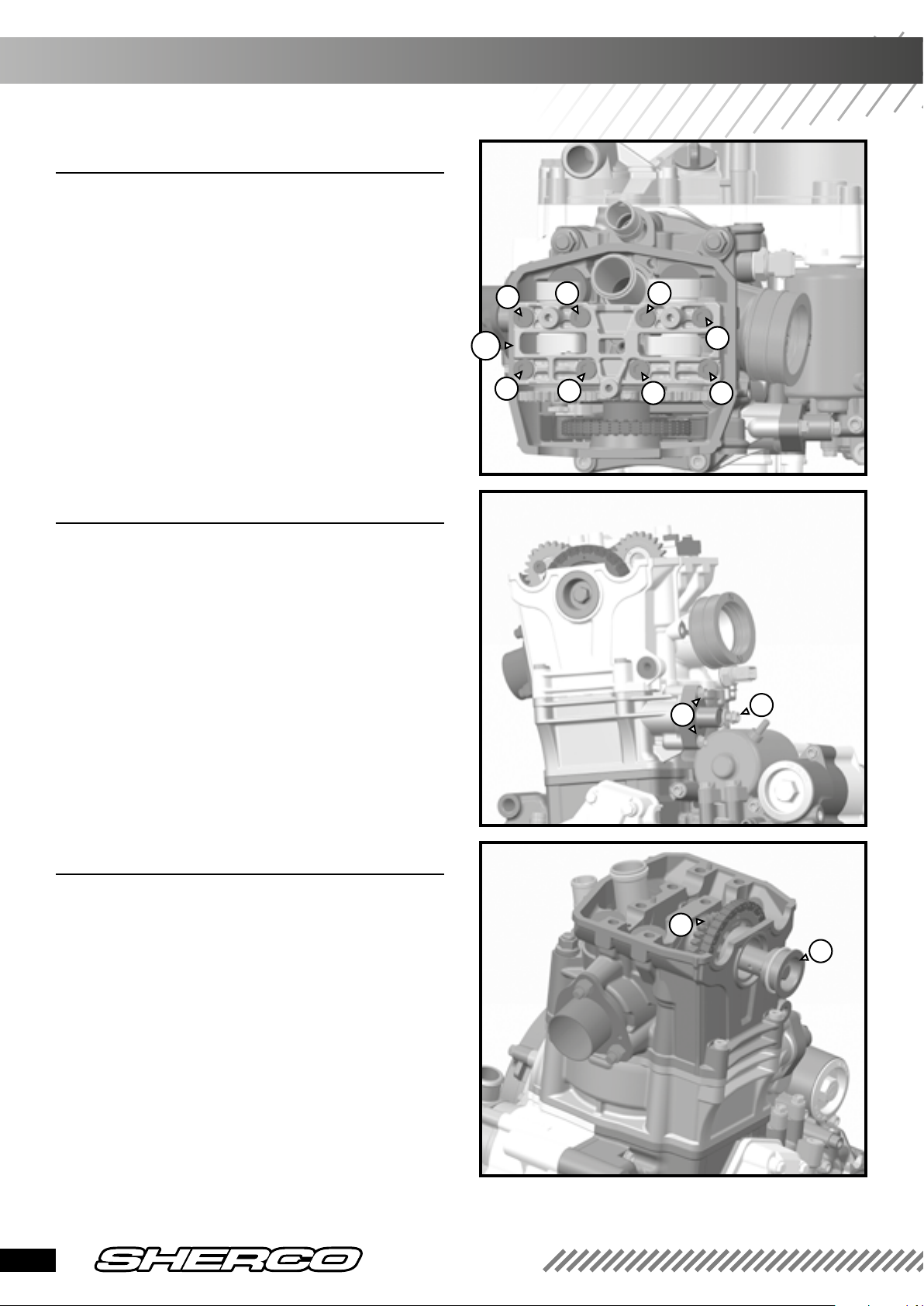
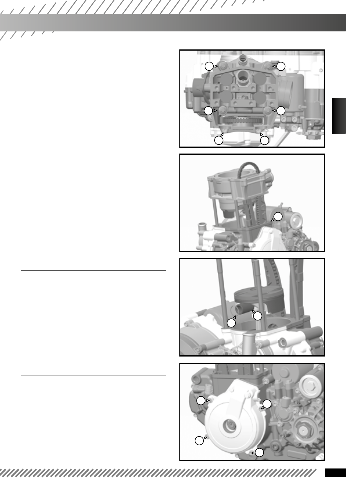
❱❘ Removing the camshafts
• Unscrew the eight screws from the shaft
bearing cap cam following the order shown in the
picture.
• Remove the bearing cap (A).
• Remove the camshafts.
4
68
❱❘ Removing the distribution tensioner
• Unscrew the screw (1) and remove the spring.
• Unscrew the two screws (2).
• Remove the tensioner along with its gasket.
A
3
7
5
2
1
2
1
❱❘ Removing the drive chain
• Remove the shaft (1).
• Hold the pinion (2) and disengage the chain.
• Remove the pinion (2).
• Remove the timing tool from the top dead cen-
ter position 1819.
14
2
1
450 SEF-R
REMOVING THE ENGINE
❱❘ Removing the cylinder head
• Unscrew the cylinder head bolts following the
orderindicated in the picture.
• Remove the cylinder head by pulling it vertically.
• Remove the cylinder head gasket with caution.
6
3
❱❘ Removing the cylinder
• Remove the cylinder by it pulling vertically.
• Remove the cylinder gasket (1) carefully.
❱❘ Removing the piston
4
5
ENGLISH
2
1
1
• Remove the securing clip (1) from the piston pin
and remove the piston pin (2).
• Remove the piston.
❱❘ Removing the ignition cover
• Remove the 4 screws (1) and remove
the ignition cover.
• Remove the ignition cover gasket with caution.
2
1
1
1
1
1
15
❱❘ Changing the stator and the engine
speed sensor
• Remove the 2 screws from the sensor (2) and
the two screws from the stator (1).
• Set up the new parts.
• Reinstall the screws with red thread lock
and tighten to 7 Nm,
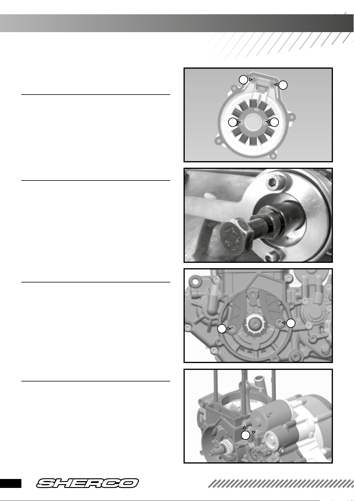
❱❘ Removing the rotor
• Use the rotor maintenance tool 4753.
• Unblock the central nut.
• Extract the flywheel with the flywheel
extractor R462.
2
2
1 1
❱❘ Removing the drive chain
• Unscrew the drive chain guide plates (1) and (2).
• Remove the drive chain.
❱❘ Removing the electric starter
• Unscrew the two screws (1) and pull
horizontally to the left.
Remove the oil filter, if not done yet.
1
2
1
16
450 SEF-R
REMOVING THE ENGINE
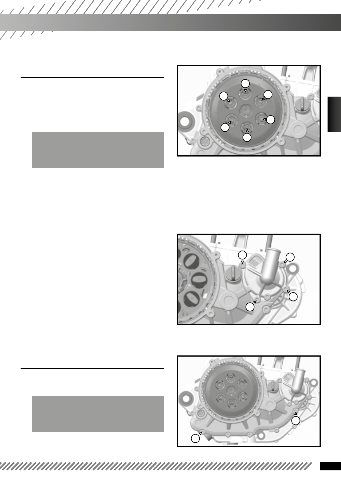
❱❘ Removing the clutch
• Remove the clutch housing cover by unscrewing
the 4 screws. Beware of the O-ring located on the
rim of the cover.
• Set the TDC 1819 tool.
WARNING
Do not use this tool for tightening or loosening
with a torque value higher than 10 Nm.
• Remove the 6 screws from the pressure plate.
• Remove the friction and metal plates.
• Make sure the inner clutch hub can freely
rotate.
❱❘ removing the water pump housing
4
2
5
3
6
1
ENGLISH
• Remove the screws (1) of the water pump
housing.
Beware of the O-ring located on the rim.
❱❘ Removing the clutch housing
• Dismount the 8 screws of the clutch housing.
WARNING
You need to identify the screws,
6 are 25 mm long, 2 are 30mm long (screw (1)).
1
1
1
1
1
• Remove the clutch housing and remove
the seal carefully.
1
17
❱❘ DRemoving the water pump oil seal
and the bearing
• Remove the water pump turbine with a 10 soc-
ket by unscrewing it while holding the drive pinion.
• Remove the water pump shaft. Both oil seals
have been made accessible.
WARNING
The 2 seals are not identical
nor are they interchangeable.
• Disconnect the shaft from the water pump
drive pinion.
• Remove the water pump bearing.
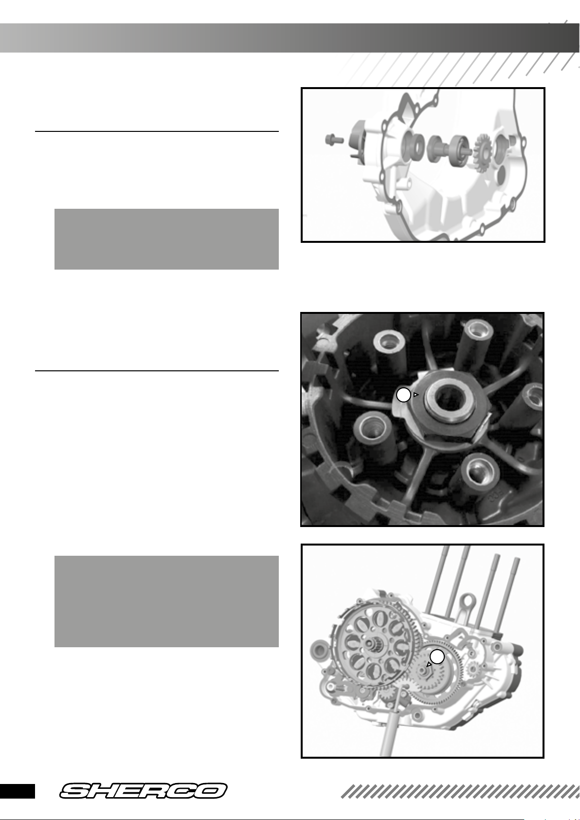
❱❘ Removing the clutch bellhousing
• Remove the finger follower from the clutch hub
• Flatten the safety tab.
• Block the clutch hub using the 5749 and uns-
crew the nut.
• Remove the hub, the notched washer and the
bellhousing.
• Remove the drive pinion of the oil pump if it
does has not remained stuck to the bellhousing.
• Check the needle bearings and change them if
necessary
• Visually check the clutch bellhousing.
WARNING
If you want to dismount the freewheel or the balancer
shaft further on, block the primary drive with the
tool 5593. Unlock the nut off the mass of the balancer
shaft (2).
1
2
18
450 SEF-R
REMOVING THE ENGINE
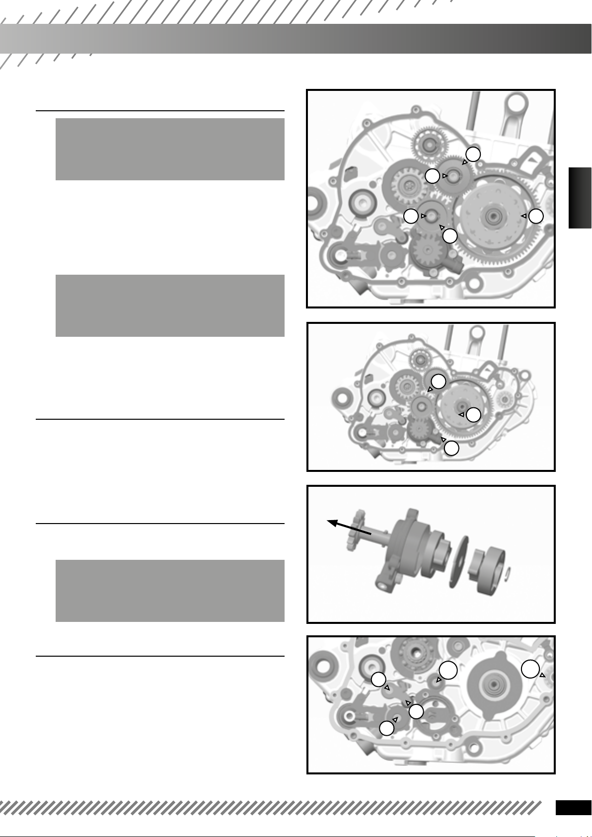
❱❘ Removing the freewheel sprocket
WARNING
See previous paragraph for the unlocking of the
balancer shaft nut.
• Remove the securing clip (1) and their washers.
• Remove the torque limiter (2).
• Remove the oil pump intermediate pinion (3).
• Unscrew the nut and remove the freewheel
bellhousing (4) with a 2-arm puller.
WARNING
Do not damage the end of the crankshaft: oil passage,
pin lubrication and lip sealing.
2
1
1
3
4
FRANÇAIS
ENGLISH
• Remove the freewheel sprocket.
❱❘ Removing the oil pump
• Remove the oil pump intermediate pinion.
• Remove the 3 screws (1).
❱❘ Changing the oil pump
• Remove the securing clip in pin end condition
and remove it.
WARNING
The pump to the left of the wall is 8 mm thick and the
one to the right is 12 mm thick.
❱❘ Removing the index shim
1
1
1
• Keep the selection locking latch blocked (1)
• Pull on the scorpion and remove the selector
shaft.
• Unblock the index shim and the locking latch
with an Allen key (2)
2
A
1
2
B
19
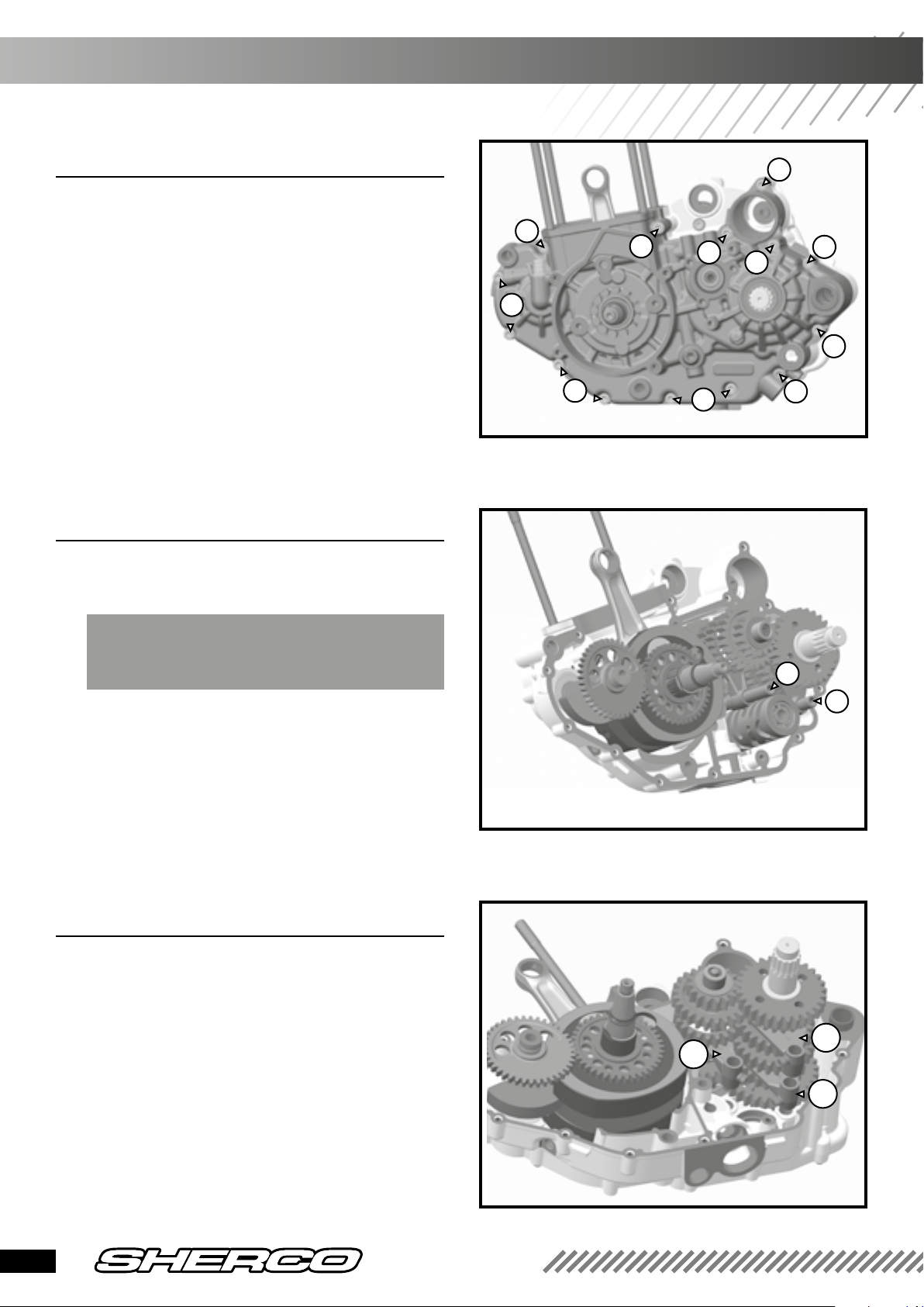
❱❘ Separating the central crankcases
• Remove the screw (A - p. 19) with an Allen key.
• Remove the water pump drive pinion (B - p.19)
by removing the securing clip. Beware of the needle
that may fall.
• Turn the housing over and remove the 14 screws
of the central crankcase: (1) length 45 mm x 10; (2)
length 55 mm x 1; (3) length 75 x 3.
• Separate the central crankcases.
1
1
1
3
3
3
1
1
❱❘ Removing the gearbox
• Remove the two fork spindles (1).
• Remove the selection drum.
BEWARE
of the small fork sockets.
• Remove the forks C, L and R.
• Remove the two gearbox shafts.
1
1
2
1
1
❱❘ Removing the crankshaft
• Remove the balancer shaft.
• Remove the crankshaft.
20
R
C
L
450 SEF-R
Checking individual parts
❱❘ Controlling the central crankcases
• Check the general condition of the central cran-
kcases for any possible damage or crack.
Change the defective or worn crankcase set if
necessary.
• Check the condition of the bearings. Change
them if necessary.
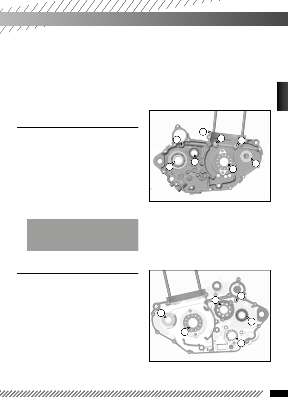
❱❘ Left crankcase
ENGLISH
• The crankshaft bearings (1), primary shaft (2)
and secondary shaft (3) of the gearbox are held by
some screws and/or plates.
• Balancer shaft bearing (4).
• Check the bearings, replace them if necessary.
• Remove the bearings.
• Check that their housing is clean and install the
new bearings, hot crankcase at about 70 °C.
• Apply blue thread lock on the bearings of the
retaining screws and tighten them to 5 Nm.
• Check that the top engine oil nozzle (5) and BV
(6) is not clogged or damaged.
WARNING
the piston nozzles (7) are indexed and cannot be
replaced. If damaged, replace the carters.
❱❘ Right crankcase
5
6
2
3
7
7
4
1
• The crankshaft bearings (1), primary shaft (2)
and secondary shaft (3) and selection drum (4) are
secured by screws and/or plates.
• Balancer shaft bearing (5).
• Check the bearings, replace them if necessary.
• Remove the bearings.
• Check that their housing is clean and reinstall
the new bearings, hot crankcase at about 70 °C.
• Apply blue thread lock on the bearings of the
retaining screws and tighten them to 5 Nm.
• Check that the oil nozzle (6) and (7) (external
side) is not clogged.
2
6
5
3
1
4
21
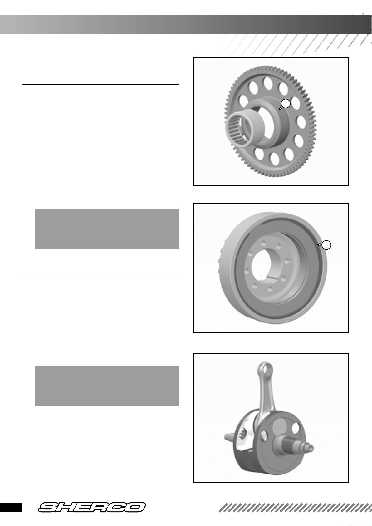
❱❘ Checking the freewheel sprocket
bearinge
• Visually check the needle bearing of the
freewheel sprocket.
• Change it if necessary.
• Check the visual aspect of the rolling raceway
of the freewheel sprocket (1).
• Change the pinion if necessary.
• Check the visual aspect of the freewheel, its
clearance with your hand, as well as its capacity to
freely rotate.
• Replace it if necessary; remove the outer
securing clip (2) and remove the freewheel.
WARNING
Replacing the freewheel systematically involves
replacing the freewheel sprocket and vice versa.
1
2
❱❘ Changing the crankshaft bearings
• Change the corresponding bearings (outer rings)
on the central crankcases.
• Pull out the distribution drive pinions with a
2-arm puller.
• Retrieve the inner rings of the crankshaft
bearings by heating the R464 tool and the ring.
WARNING
The radial clearance of the bearings must be
practically zero.
• To remove the drive pinion of the balancer shaft,
tighten 2 screws 8 x 125 in the holes provided for
this purpose.
22
450 SEF-R
Checking individual parts
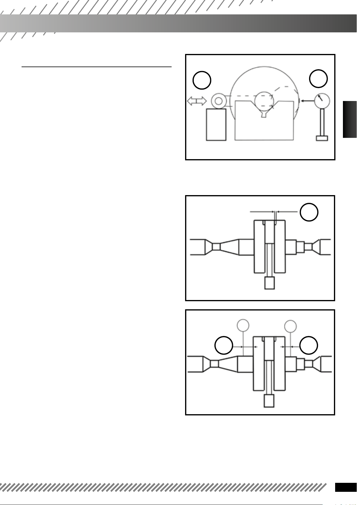
❱❘ Checking the crankshaft
Radial clearance of the connecting rod:
• Place the crankshaft on V-blocks and place a
dial gauge [A] against the connecting rod.
• Push [B] the connecting rod to the gauge and
then in the opposite direction. The difference
between those two measurements is the radial
clearance.
Radial clearance of the connecting rod:
Standard: 0.008 mm - 0.012 mm
Tolerated limit: 0.05 mm
If the radial clearance exceeds the limit, the crankshaft must be replaced.
Lateral clearance of the connecting rod:
• Measure lateral clearance of the connecting rod [A].
Lateral clearance of the connecting rod:
Standard: 0.6 mm - 0.85 mm
Tolerated limit: 1.1 mm
B
A
ENGLISH
A
If the radial clearance exceeds the tolerated limit,
replace the crankshaft.
Checking the runout:
• Place the crankshaft on alignment devices or V-
blocks, and place a gauge as shown in the image.
• Then slowly turn the crankshaft. The maximum
difference between the measurements corresponds
with the offset of the crankshaft.
Runout:
Standard: 0.02 mm maximum
Tolerated limit: 0.08 mm
If the offset is not correct, replace the crankshaft
and align it so to be within tolerated limits.
AA
23
 Loading...