

SHERCO 125 SE-R 2017 Workshop Manual
MANUEL D’ATELIER I WORKSHOP MANUAL I MANUAL DE
TALLER

125 SE-
2
CONTENTS
PREAMBLE ....................................................................................................................................................................................................................................................................................................................................................................................................... 4
LIST OF ENGINE TOOLS .......................................................................................................................................................................................................................................................................................................................................................................... 5
TECHNICAL CHARACTERISTICS ...................................................................................................................................................................................................................................................................................................................................................... 6
❱❘
Engine ...................................................................................................................................................................................................................................................................................................................................................................... 6
❱❘
Cycle part ................................................................................................................................................................................................................................................................................................................................................................. 7
ORIGINAL SETTINGS ................................................................................................................................................................................................................................................................................................................................................................................. 8
❱❘
Yoke .......................................................................................................................................................................................................................................................................................................................................................................... 8
❱❘
Shock absorber .................................................................................................................................................................................................................................................................................................................................................... 9
OPERATIONS REQUIRING ENGINE REMOVAL OR NOT I ............................................................................................................................................................................................................................................................................................. 10
ENGINE REMOVAL / ASSEMBLY ..................................................................................................................................................................................................................................................................................................................................................... 11
❱❘
Engine removal .................................................................................................................................................................................................................................................................................................................................................. 11
❱❘
Reassembly of the engine into its frame ................................................................................................................................................................................................................................................................................................... 12
ENGINE DISASSEMBLY ......................................................................................................................................................................................................................................................................................................................................................................... 14
❱❘
Gearbox drainage ............................................................................................................................................................................................................................................................................................................................................. 14
❱❘
Removal of the pinion and selector ............................................................................................................................................................................................................................................................................................................. 14
❱❘
Removal of the cylinder head, the cylinder and the piston ................................................................................................................................................................................................................................................................. 15
❱❘
Disassemble the clutch casing ..................................................................................................................................................................................................................................................................................................................... 16
❱❘
Removal of both the pressure tray and discs ......................................................................................................................................................................................................................................................................................... 16
❱❘
Removal of the electric starter ........................................................................................................................................................................................................................................................................................................................ 17
❱❘
Removal of the main transmission ............................................................................................................................................................................................................................................................................................................. 17
❱❘
Removal of the locking mechanism........................................................................................................................................................................................................................................................................................................... 18
❱❘
Removal of the ignition casing....................................................................................................................................................................................................................................................................................................................... 19
❱❘
Removal of the ignition ..................................................................................................................................................................................................................................................................................................................................... 19
❱❘
Removal of the starter ...................................................................................................................................................................................................................................................................................................................................... 20
❱❘
Intake pipe and clapper box ........................................................................................................................................................................................................................................................................................................................... 20
❱❘
Separate out the half-casings ........................................................................................................................................................................................................................................................................................................................ 21
❱❘
Removal of the speed selection ................................................................................................................................................................................................................................................................................................................... 21
❱❘
Removal of the rod assembly ....................................................................................................................................................................................................................................................................................................................... 22
ENGINE PART CONTROL ..................................................................................................................................................................................................................................................................................................................................................................... 23
❱❘
Connecting rod assembly .............................................................................................................................................................................................................................................................................................................................. 23
❱❘
Balance masses, verification of the exterior side .................................................................................................................................................................................................................................................................................... 23
❱❘
Radial clearance of the crank head ............................................................................................................................................................................................................................................................................................................ 23
❱❘
Crank head lateral clearance ........................................................................................................................................................................................................................................................................................................................ 24
❱❘
Control of the crankshaft radial runout ........................................................................................................................................................................................................................................................................................................ 24
❱❘
Piston ...................................................................................................................................................................................................................................................................................................................................................................... 24
❱❘
Cross-sectional clearance .............................................................................................................................................................................................................................................................................................................................. 24
❱❘
Standard exchange cylinder / Squish control ......................................................................................................................................................................................................................................................................................... 26
❱❘
Disassemble the exhaust valve system ................................................................................................................................................................................................................................................................................................... 27

3
❱❘
Control of valve operations ............................................................................................................................................................................................................................................................................................................................. 29
❱❘
Adjustment of the exhaust valve pulley clearance ................................................................................................................................................................................................................................................................................ 30
❱❘
Clapper box, pipe intake sleeve ................................................................................................................................................................................................................................................................................................................... 31
❱❘
Clutch ...................................................................................................................................................................................................................................................................................................................................................................... 31
ENGINE REASSEMBLY .......................................................................................................................................................................................................................................................................................................................................................................... 32
❱❘
Connecting rod assembly .............................................................................................................................................................................................................................................................................................................................. 32
❱❘
Transmission gearbox ..................................................................................................................................................................................................................................................................................................................................... 32
❱❘
Assembly of the half-casings ......................................................................................................................................................................................................................................................................................................................... 33
❱❘
Selection mechanism ...................................................................................................................................................................................................................................................................................................................................... 34
❱❘
Main transmission and clutch ........................................................................................................................................................................................................................................................................................................................ 35
❱❘
Clutch discs, pressure plate ............................................................................................................................................................................................................................................................................................................................ 36
❱❘
Clutch casing........................................................................................................................................................................................................................................................................................................................................................ 36
❱❘
Piston and cylinder ............................................................................................................................................................................................................................................................................................................................................. 37
❱❘
Cylinder head ...................................................................................................................................................................................................................................................................................................................................................... 37
❱❘
Clapper box and pipe intake .......................................................................................................................................................................................................................................................................................................................... 38
❱❘
Gearbox output pinion ...................................................................................................................................................................................................................................................................................................................................... 38
❱❘
Assembly of the ignition starter ...................................................................................................................................................................................................................................................................................................................... 38
❱❘
Ignition assembly and its lid ............................................................................................................................................................................................................................................................................................................................. 39
❱❘
Assembly of the electric starter ...................................................................................................................................................................................................................................................................................................................... 39
TABLE OF TIGHTENING TORQUES............................................................................................................................................................................................................................................................................................................................................... 40
TABLE OF CARBURETTOR SETTINGS ....................................................................................................................................................................................................................................................................................................................................... 42
❱❘
Table of settings for the SE-R 125 carburettor: ....................................................................................................................................................................................................................................................................................... 42
LOAD CIRCUIT CONTROL .................................................................................................................................................................................................................................................................................................................................................................... 43
❱❘
Static control values (engine turned off) 125 SE-R ............................................................................................................................................................................................................................................................................... 43
❱❘
Dynamic control values ................................................................................................................................................................................................................................................................................................................................... 43
WIRE MAP ........................................................................................................................................................................................................................................................................................................................................................................................................ 44
❱❘
Main bundle 6827 .............................................................................................................................................................................................................................................................................................................................................. 44
❱❘
Light beam 125 SE-R ...................................................................................................................................................................................................................................................................................................................................... 46
❱❘
Racing light beam 125 SE-R ........................................................................................................................................................................................................................................................................................................................ 47
❱❘
Accessory bundle .............................................................................................................................................................................................................................................................................................................................................. 48

125 SE-
4
PREAMBLE
The present manual is primarily intended for certified mechanics working in an
appropriately equipped workshop.
Performing the various operations requires both a solid knowledge in mechanics and the set
of SHERCO tools specific to the 125 SE-R engines.
This workshop manual serves as a complement to the SHERCO 125 SE-R user’s manual.

5
LIST OF ENGINE TOOLS
❱❘ 125 SE-R
Tooling reference
Designation
1814
Clutch drum block
1815
Ignition block
2067
Oscillating arm shaft tool
2072
Right-hand casing primary shaft bearing tool
2074
Secondary shaft bearing tool
R467
Out-of-gearbox shaft bearing tool
2069
Out-of-gearbox gasket tool
2071
Right-hand drum bearing selection tool
5398
Left-hand drum bearing selection tool
5399
Crankshaft bearing tool
2069
Crankshaft gasket tool
5402
HK0808 needle bearing cage tool
(water pump, starter)
1968
Water pump gasket tool
1821
Engine support
1817
Primary pinion block tool
2073
Spring block (finger pointing device)
R462
Magnetic wheel wrench
R464
Crankshaft ring extractor
R453
Selected shaft bearing assembly tool
R444
Gasket selector tool
125 SE-
6
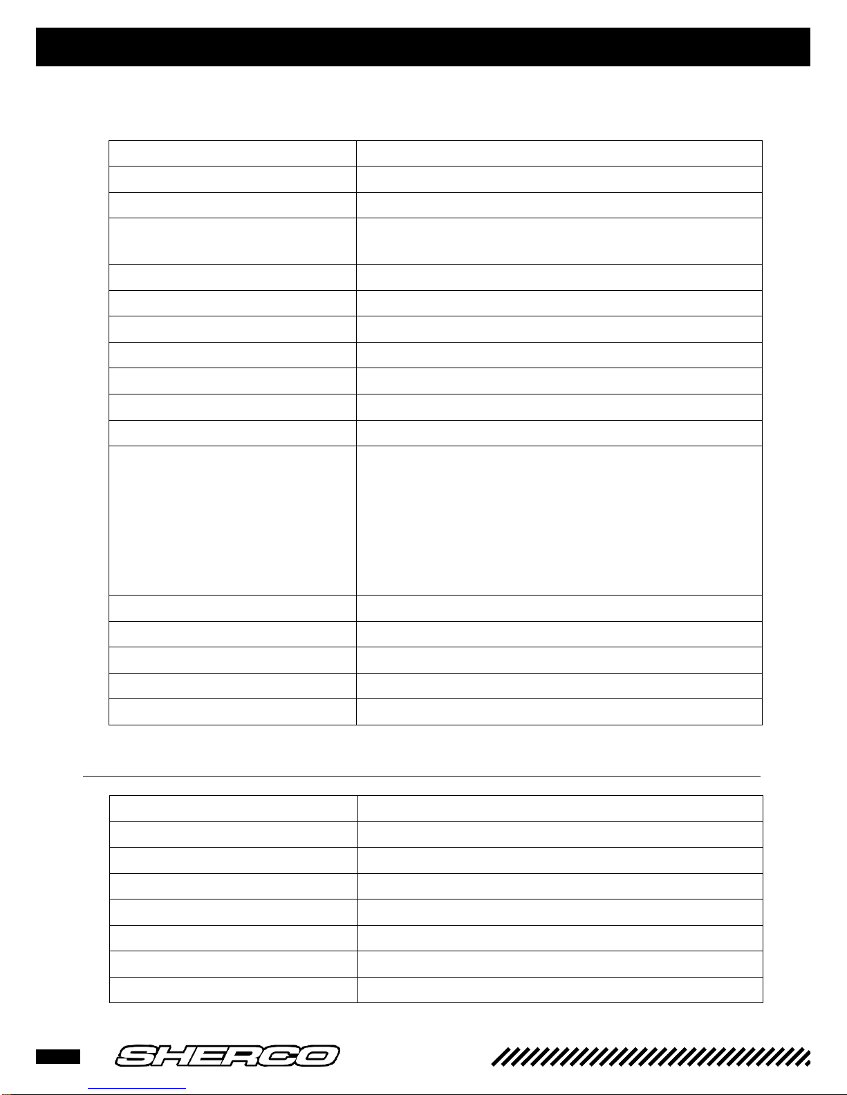
TECHNICAL CHARACTERISTICS
❱❘ Engine
Type
Liquid cooled, 2-stroke single cylinder
Displacement
124.81 CC
Bore diameter / Stroke
54 / 54.5 mm
Gasoline
Unleaded with an octane index of at least 95 mixed with two-stroke oil (2%)
Coolant
with forced circulation
Ignition system
A DC-CDI without a contact breaker, digital advance
Spark plug
NGK BR9ECMIX
Distance between spark plug electrodes
0.7 mm
Piston
Forged aluminium
Motor oil
500 ml SAE 10W40
Main transmission
20 x 72
Gearbox:
1
st
2nd
3rd 4th
5th 6th
6 speeds
15: 33
17: 30
19: 28
21: 26
23: 24
25: 22
Final transmission
13 x 51
Clutch
Multi-disc in an oil bath, hydraulic controls
Ignition
Electric starter
Battery
12 V 4 Ah
Alternator
220 W
❱❘ Carburettor
Type of carburettor
KEIHIN PWK 36S AG
Needle position
3rd position from the top
Injector needle
N1EG
Main injector
KEA 168 (KEA 115)
Braking injector
KEP 42 (KEA 38)
Starter injector
85 (50)
Opening of the air regulator screws
1 T 1/4
Sliding gate section
5.5
7
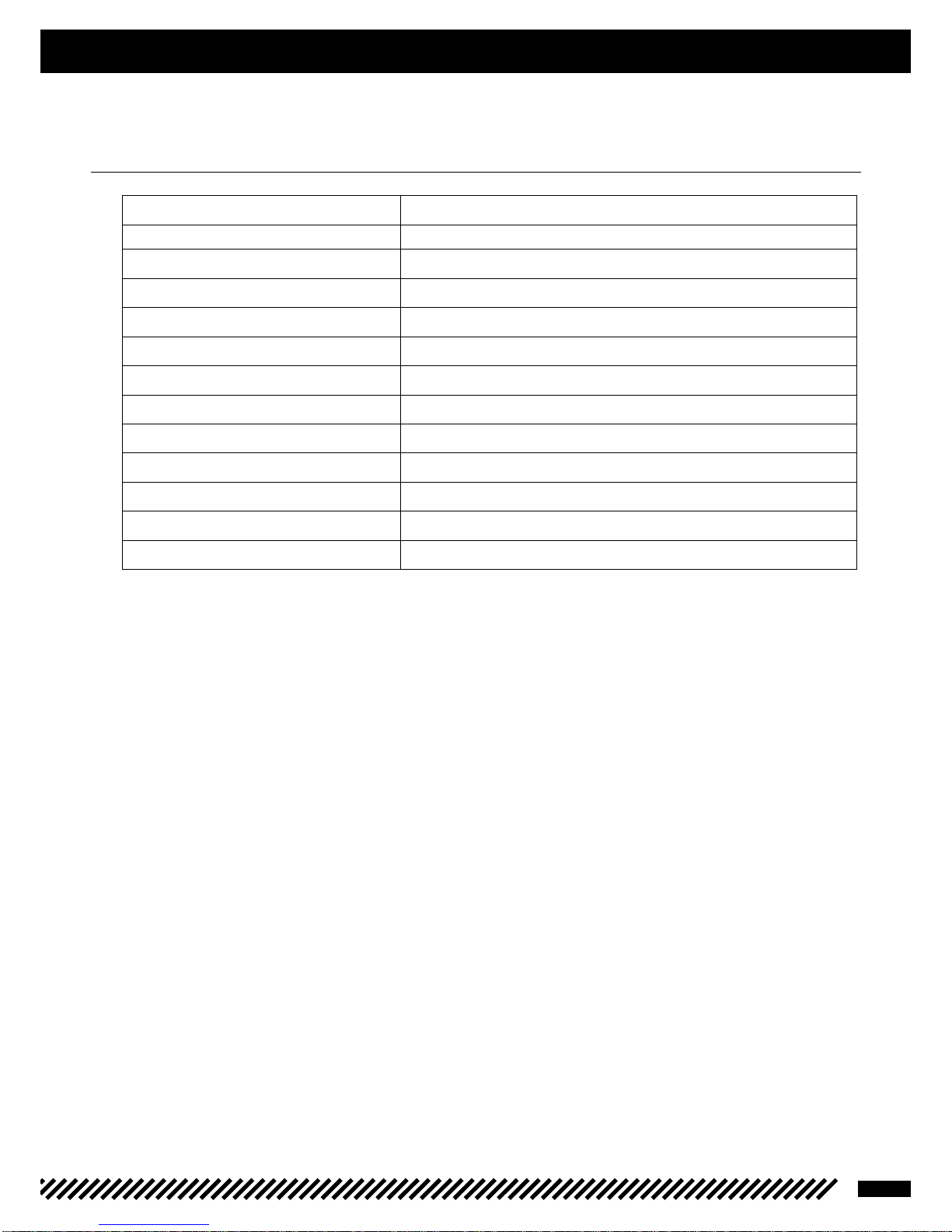
TECHNICAL CHARACTERISTICS
❱❘ Cycle part
Frame
Semi-perimeter made of CrMo steel with an aluminium back clip
Yoke
WP suspension X Plor Ø48 mm
Rear suspension
WP suspension with a separate cylinder, oscillating aluminium arm
Front/back stroke
300/330 mm
Front brake
disc Ø 260 mm
Rear brake
Disc Ø 220 mm
Disc brakes
Wearing limit: 2.7 mm front and 3.6 mm rear
Front tyre
90/90-21’’
Rear tyre
140/80-18’’
Front/rear off-road pressure
0.9 bar
Gasoline tank capacity
10.4 l, including 1 litre in reserve
Steering column angle
25.9°
Wheelbase
1,465 mm
125 SE-
8
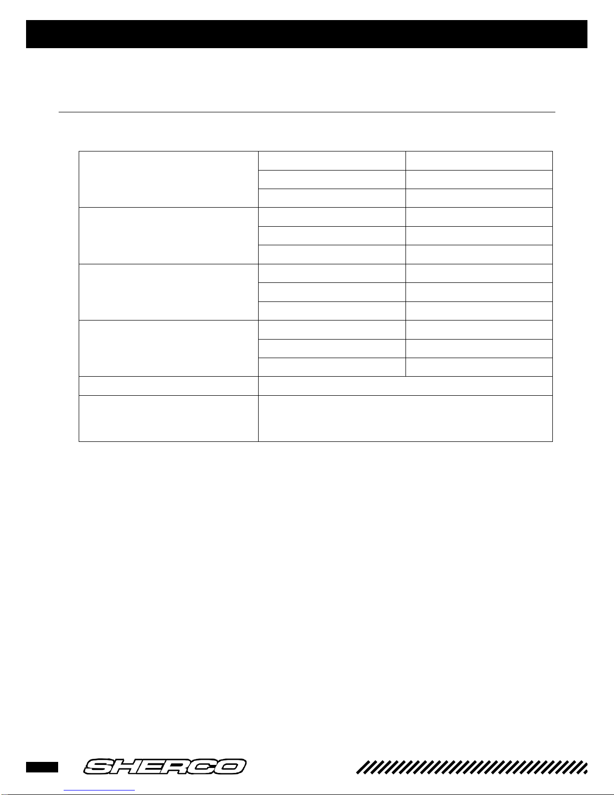
ORIGINAL SETTINGS
❱❘ Yoke
Original settings - WP yoke suspension X Plor Ø48 mm
Compression
Comfort
14 clicks backwards
Standard
12 clicks backwards
Sport setting
10 clicks backwards
Recreation
Comfort
14 clicks backwards
Standard
12 clicks backwards
Sport setting
10 clicks backwards
Prestressing
Comfort
0 Clicks
Standard
1 Click (+3)
Sport setting
2 Clicks (+6)
Spring stiffness
Rider’s weight: 65-75 kg
3.8 N/mm
Rider’s weight: 75-85 kg
4.0 N/mm (origin)
Rider’s weight: 85-95 kg
4.2 N/mm
Type of oil
SAE 4
Measured oil level (compressed yoke
and without spring action) from the
top of the upper tube
110 mm
9
ORIGINAL SETTINGS
❱❘ Shock absorber
Original settings - WP suspension shock absorber
Low-speed compression
Comfort
20 clicks backwards
Standard
12 clicks backwards
Sport setting
6 clicks backwards
High-speed compression
Comfort
2 revolutions backwards
Standard
1.5 revolutions backwards
Sport setting
1 revolution backwards
Recreation
Comfort
15 clicks backwards
Standard
12 clicks backwards
Sport setting
6 clicks backwards
Spring stiffness
Rider’s weight: 65-75 kg
42 N/mm
Rider’s weight: 75-85 kg
45 N/mm (original setting)
Rider’s weight: 85-95 kg
48 N/mm

125 SE-
10
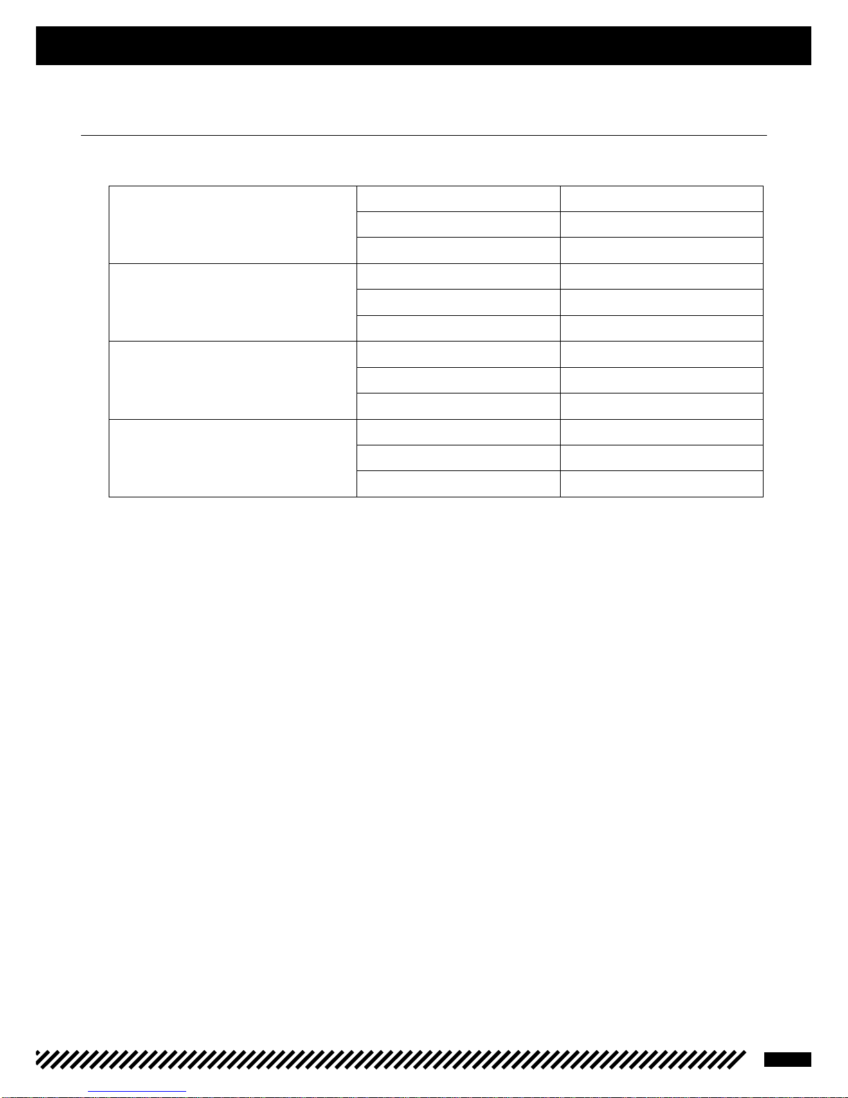
OPERATIONS REQUIRING ENGINE REMOVAL OR NOT I
Operation requiring engine
removal
Operation not requiring engine
removal
Crankshaft (including the crank kit)
•
Complete gearbox
•
Crankshaft bearing
•
Gearbox bearing
•
Piston
•
Cylinder
•
Cylinder head
•
Ignition
•
Starter gear set
•
Complete clutch
•
Water pump
•
Speed selection assembly
•
11
ENGINE REMOVAL / ASSEMBLY
❱❘ Engine removal
-
Drainage (see User’s Manual)
•
Motor oil
•
Coolant
-
Remove the saddle.
-
Disconnect the battery.
-
Unhook the tank using its louvres.
-
Disconnect the wire harness attached to the engine (starter lug, anti-parasitic device).
-
Remove the exhaust (see User’s Manual).
-
Remove the carburettor.
-
Remove the secondary transmission chain (quick fasteners).
-
Remove the chain protection.
-
Remove the clutch slave cylinder.
-
Remove the water hoses connected to the engine.
-
Remove the left side radiator.
-
Unscrew the entire set of engine screws.
-
Loosen the oscillating arm shaft.
-
Remove the cylinder head-frame retaining brackets and corresponding electric engine.
-
Remove the engine shafts.
-
Remove the oscillating arm shaft.
-
Unhook the valve cables from their pulley.
-
Remove the engine.
CAUTION
Once the clutch slave cylinder has been removed, the piston is no longer being maintained. Hold the piston pressed
down using a plastic collar.
125 SE-
12
ENGINE REMOVAL / ASSEMBLY
❱❘ Reassembly of the engine into its frame
For the reassembly step, proceed in the opposite order from disassembly, in complying with the tightening
torques of both screws and nuts: Engine screws: 60 N-m
Oscillating arm nut: 100 N-m
Clutch slave cylinder screws: 10 N-m
Cylinder head-frame screws: 23 N-m
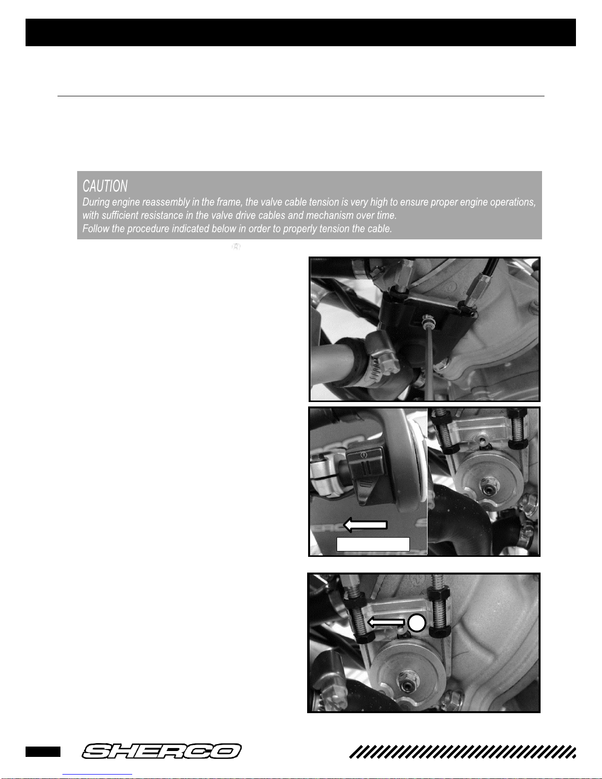
-
Remove the two M4 screws and withdraw the
valve pulley cover plate.
-
Place the mapping contactor in the “Soft”
position (toward the left) and place the
motorcycle contact switch in the ON position.
Wait for completion of the electric engine valve
initialisation and its subsequent shut-off.
Turn off the motorcycle contact switch and
check that the pulley is correctly positioned
facing left.
-
Proceed with the left cable tension adjustment
[1] so as to remove all slack from the pulley.
SOFT POSITION
1
13
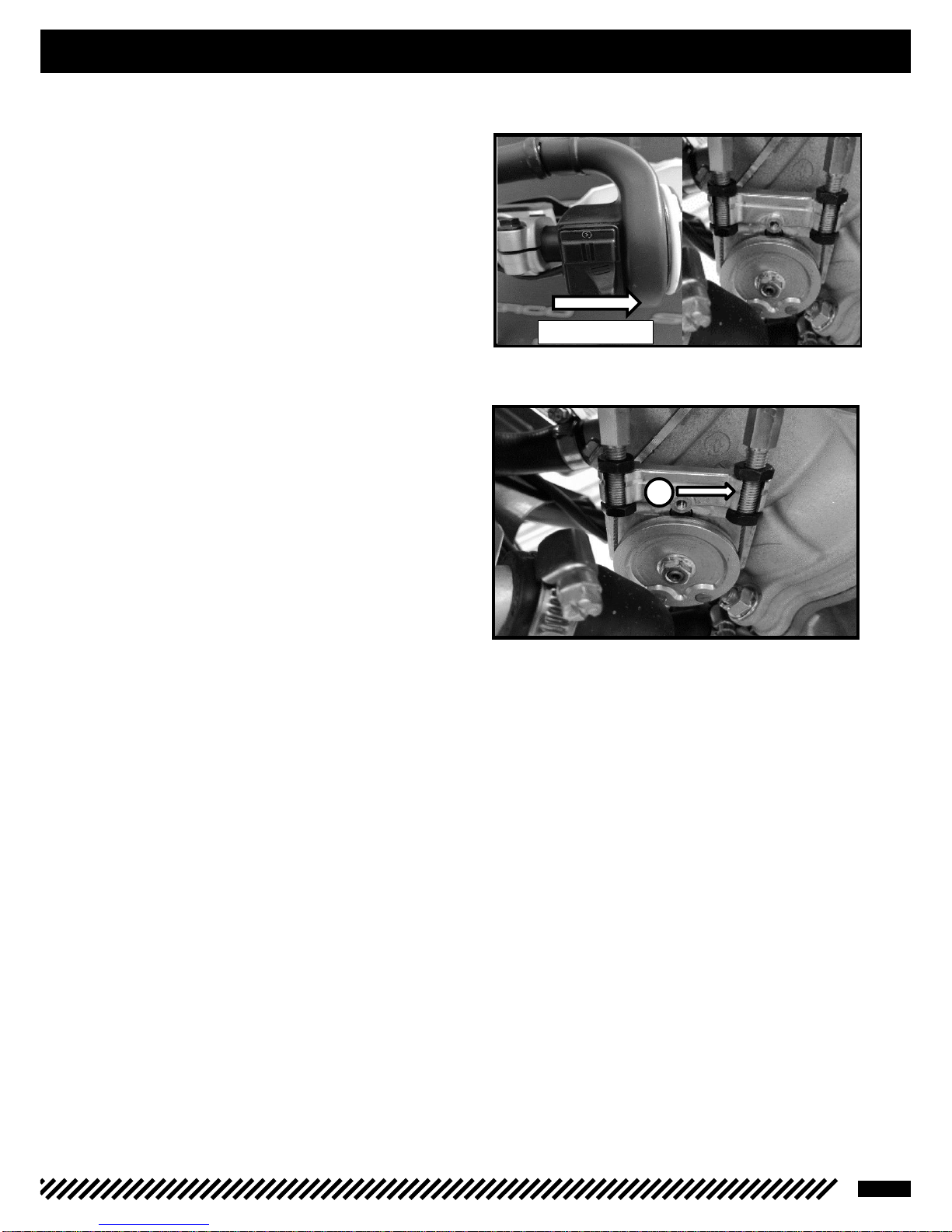
ENGINE REMOVAL / ASSEMBLY
-
Place the mapping contactor in the “Hard”
position (toward the right) and turn on the
motorcycle contact switch.
Wait for completion of the electric engine valve
initialisation and its subsequent shut-off.
Turn off the motorcycle contact switch and
check that the pulley is correctly positioned
facing right.
-
Proceed with the right cable tension adjustment
[2] so as to remove all slack from the pulley.
-
Verify the effective operations of valves by
placing the motorcycle contact switch in the ON
position and transitioning from the “Hard” curve
to the “Soft” curve.
HARD POSITION
2
125 SE-
14
ENGINE DISASSEMBLY
For the blow-up drawings, please refer to the 125 SE-R spare parts catalogue
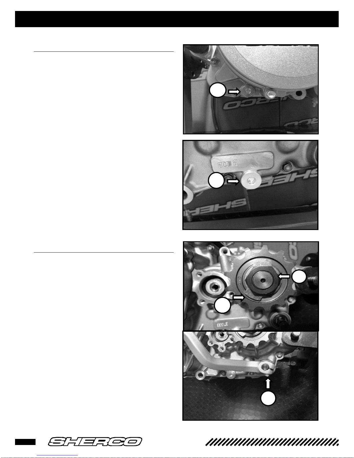
❱❘ Gearbox drainage
-
Remove drainage plugs [1] and [2], let the oil
flow out.
❱❘ Removal of the pinion and selector
-
Unfold the safety washer tab [3] using a pushing
device.
-
Remove the gearbox output pinion [4].
-
Remove the screw first [5] first and then the
selector.
-
Release the clutch control rod.
1
2
1 4 3
5
2
15
ENGINE DISASSEMBLY
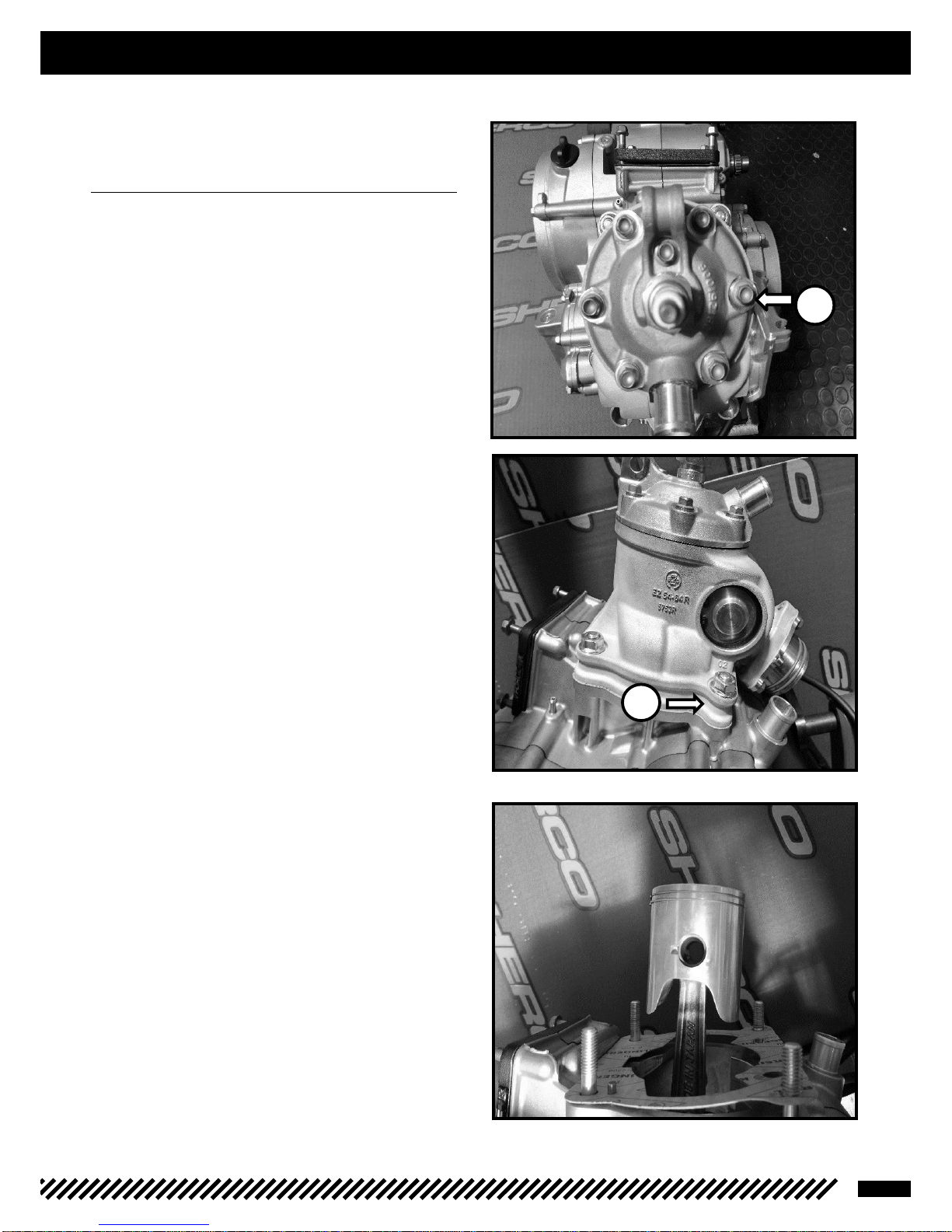
❱❘ Removal of the cylinder head, the
cylinder and the piston
-
Remove the shoulder screws [1] and release
both the cylinder head and the two O-rings
-
Remove all four nuts [2] and proceed with
deinstallation.
-
Conceal the casing.
-
Remove the piston shaft clips.
-
Release the piston shaft.
-
Remove the piston and extract the needle
bearing from the connecting rod eye.
-
Remove the base joint.
3
2
1
 Loading...