

Page 1

5. Adhere to all warnings and follow all operating
instructions.
Sherbourn
Te c h n o l ogies, Inc.
Model LDS2/75
Owner’s Manual
Thank you so much for your decision to purchase
one of our superb Sherbourn amplifiers. We take
enormous pride in the design and build quality of
all of our products and we are confident that our
product will provide you with many years of enjoyable and trouble-free service. Should you have
any need to call upon our services please feel free
to contact us at the address shown at the end of this
booklet; or, of course, you can contact the dealership from which you purchased the product.
Full details of the warranty coverage provided by
Sherbourn T echnologies can be found at the end of
this booklet.
6. Warning: To reduce the risk of fire or electrical shock, do not expose this equipment to rain
or moisture.
There are no user serviceable parts inside. Refer
servicing to qualified personnel.
7. Caution: To prevent electrical shock do not use
this (polarized) plug with an extension cord, receptacle or other outlet unless the blades can be
fully inserted to prevent blade exposure.
8. For added protection for this product during a
lightening storm or when it is left unattended and
unused for long periods of time, it is recommended
that you unplug the unit from the wall outlet. This
will prevent damage to the product due to lightening or power line surges.
9. Do not use attachments not recommended in this
owner’s manual as they may cause hazards.
10. Locate the equipment for proper ventilation.
For example, the product should never be allowed
to operate while positioned on a bed, rug, sofa or
any such surface where proper ventilation is not
possible. Nor should the unit be placed in a builtin installation such as a cabinet or armoire, etc. in
such a way as to impede the air flow. Always ensure adequate ventilation openings - please see later
comments regarding such an installation.
Safety Instructions
1. Important Safety Instructions! Please read
all the safety and operating instructions shown
in this manual before operating this equipment.
2. The lightening flash within an equilateral triangle
shown above is intended to alert you to the presence of uninsulated ‘dangerous voltage’ within the
product’ s enclosure that may be of sufficient magnitude to constitute an electric shock.
WARNING
AVI S
3. The exclamation point within an equilateral triangle shown above is intended to alert you to the
presence of important operating and maintenance
(servicing) instructions in the literature accompanying this appliance.
4. Please retain this manual in a safe place for future reference about safety and operating matters.
SHOCK HAZARD - DO NOT OPEN
RISQUE DE CHOC ELECTRONIQUE
-NE PAS OUVRIR
11. Locate the product away from heat sources such
as stoves, heat registers, radiators or other appliances including other amplifiers that produce heat.
12. Mount the equipment in a wall or cabinet only
as described in this owner’s manual.
13. Do not use the equipment near water; for example near a bathtub, washbowl, kitchen sink, a
wet basement, swimming pool, etc. This product
is meant for indoor use only.
14. Do not place the product on an unstable cart,
stand tripod, bracket or table. The equipment is
heavy and should it fall, it could cause serious injury to a person and/or serious damage to the equipment.
Caution For Installation
1. Your Sherbourn amplifier can be placed on any
table or shelf. It can also be custom installed in a
rack, and/or in a piece of cabinetry or furniture of
your choice. It is however, important that if the am-
1
Page 2

plifier is going to be housed in an enclosed environment, that you allow for adequate ventilation.
Despite the adequately sized heatsinks built into
the amplifier, it is still important that good ventilation be provided. Do not install the amplifier directly above another heat generating component
such as another amplifier without adequate ventilation.
2. If your amplifier is going to be placed in an enclosed space such as an armoire, it is essential that
adequate ventilation be provided.
3. The dealership from which you purchased the
product is an expert on custom installation procedures and can provide invaluable advice to help
you make an aesthetically pleasing and trouble free
installation.
Caution For Connections
1. Connect this equipment only to the type of AC
power source as marked on the unit. Always route
AC power cords so they are not likely to be walked
on, or tripped over, or where they may be pinched
by items placed on or against them. Always pay
particular attention to cords at plugs and/or convenience receptacles, and at the point where they exit
from the product.
2. Do not defeat the inherent design features of the
polarized plug. Non-polarized line cord adapters
will defeat the safety provided by the polarized AC
plug. If the plug should fail to fit, contact your
electrician to replace your obsolete outlet. Do not
defeat the safety purpose of the grounding-type
plug. If you use this product in a country which
only has two slotted receptacles in the house, you
must use a three-pin adapter plug to earth ground
which is the “E” (earth pin) of the power cord connected to this product.
3. Do not overload wall outlets, extension or integral convenience receptacles, as this could result
in a risk of fire or shock.
Operating Voltage
The LDS2/75 amplifier is factory-set for 110V,
120V or 230V AC operation at either 50 or 60 Hz,
according to the country for which the unit was
manufactured (230V in European Union countries,
in compliance with CE regulations). The operating voltage cannot be changed by the user and any
attempt to do so will void the warranty.
not permit objects of any kind to be pushed and/or
fall into the product through the enclosure openings.
General Description
The LDS2/75 is an intuitive product that has been
designed to provide amplification for up to two
pairs of 8 ohm speakers or one pair of 4 ohm speakers.
The LDS2/75 outputs a total of 100 watts into 8
ohm loads and 150 watts into 4 ohm loads. An
embedded MPU (Micro Processing Unit) ensures
that the amplifier cannot be ’overdriven’, and the
LDS (Load Detection System) ensures that all
speaker connections must be good before the amplifier is connected to the speakers.
The LDS2/75 has an automatic internal sub-sonic
filter of -18dB per octave which rolls off very low
frequency content (below 20 Hz) to avoid low frequency saturation of a transformer volume control.
The unit can be set for a bridged/mono application
in which case the output will be 150 watts into 8
ohm loads.
The 2/75 has a great many features all of which are
described in this manual.
Front Panel Description
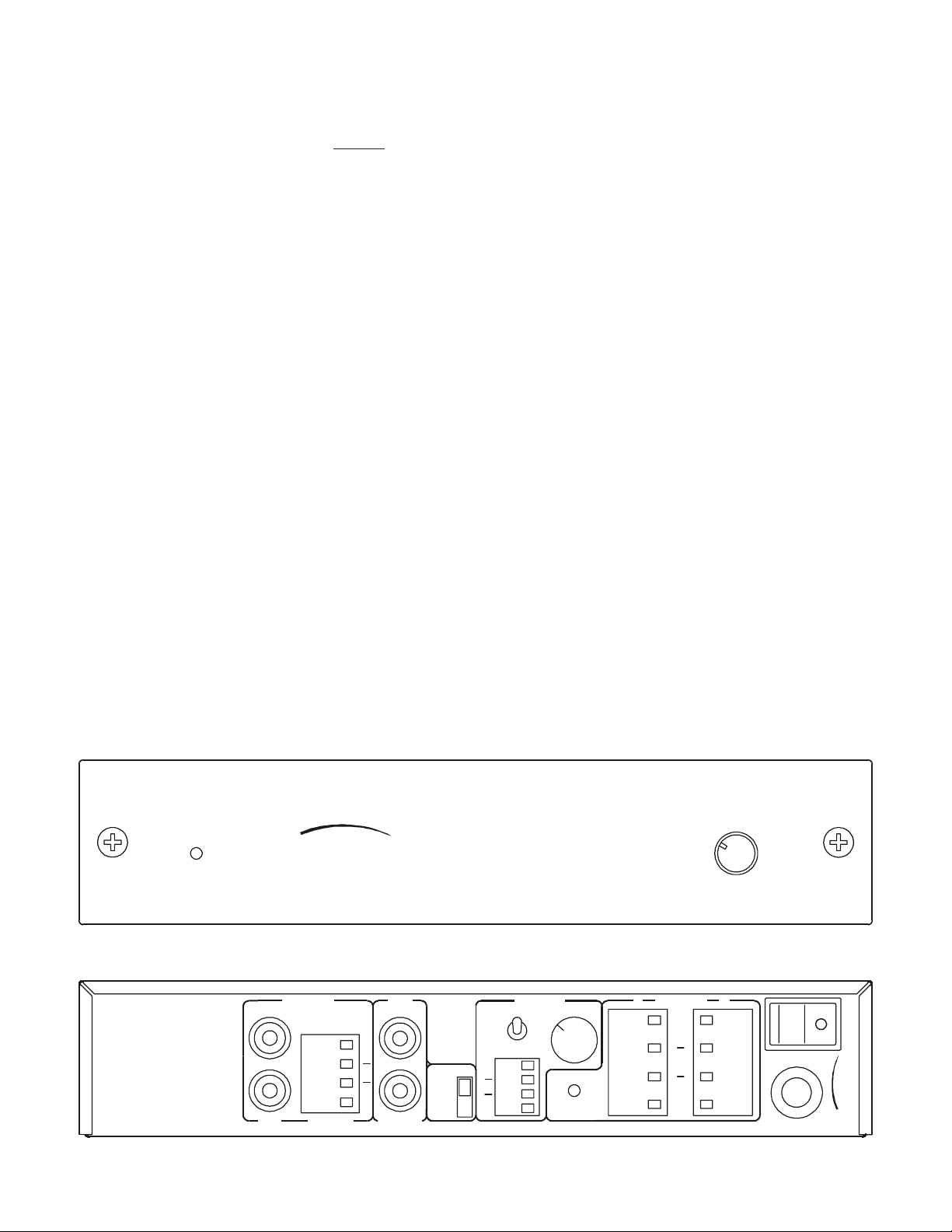
The front panel has a blue LED will glow brightly
when the unit is active and will dim considerably
whenever the unit is in its ‘sleep’ mode.
The volume control knob allows you to set a preferred level.
Rear Panel Description
The following description identifies each of the
main controls/connection options and follows the
rear panel from left to right.
Input
The amplifier offers both speaker level and line
level inputs. A “balanced” input buf fer is employed
in the speaker level input circuit that will accept
an output signal from either a ‘grounded’ or a ‘floating’ music source.
Line Output (Buffered)
For use whenever a ‘daisy-chain’ installation and
multiple LDS2/75’ s are used.
Care of the Product
Clean the product by dusting with a dry cloth. Do
2
Mode Switch
This control allows for a selection of ‘Stereo’
Page 3
‘Mono’ or ‘Mono/Bridged’. In the latter mode, the
maximum output power is 150 watts. Please note
that ‘R-Channel’ input is accepted under the
bridged operation. Bridging is
ONLY recommended when 8 Ohm speakers (or greater impedance) are used.
Music
With the LDS2/75’s trigger switch in the ‘music’
position, it will automatically function once it receives a music signal and will move into its standby
mode whenever the signal is absent for approximately five minutes. It will reactivate immediately
a signal is again received.
12 Volt Trigger
With the switch in the 12V position, the LDS2/75
can be turned on from a ‘standby’ state whenever a
6V to 15V input signal appears at the 12V input
connector.
12 Volt Connector
For 12V trigger input and output use the upper two
circuits marked ‘+IN-’ for 12V trigger input (to turn
on the LDS2/75 amplifier) and use the lower two
circuits marked ‘-Out+’ for trigger output. The input accepts only a continuous DC trigger signal
from 6V minimum to 15V maximum for turning
on the LDS2/75 amplifier .
NOTE: If the music is discontinued for longer
than 5 minutes, the LDS2/75 will automatically
enter its sleep mode to cut down on energy consumption. The front blue LED will then ‘dim’ to
indicate that the amplifier is in ‘Sleep’ and will
only return to its full luminance when it again
receives a music signal.
LDS LED
This important control indicator is provided to indicate the correctness of your speaker connections
and to indicate that the intended speaker load is
not too great for the amplifier.
Speakers 1 and 2
These are the speaker-out terminals that are connected with the cables from the loudspeakers.
Power Switch
Normally once you have switched on the amplifier
the signal sensing mode or the 12 volt trigger switch
will ensure that the amplifier goes into a ‘sleep/
standby’ mode whenever it is not being directly
used.
Protection Features
Your LDS2/75 includes some important circuits
that are designed to protect the amplifier.
The trigger output is capable of delivering a continuous 12V, 30 mA of DC current to drive the
down-stream products (or multiple units of LDS2/
75 amplifiers) that may be associated with the
LDS2/75 amplifier .
POWER
Sherbourn
Fig. 1. Front panel view
INPUT
L
R
LINE SPEAKER
OUTPUT
+
L
R
+
(BUFFERED)
LINE
MODE
STEREO
MONO
BRDG
LDS (Load Detection System)
The LDS feature is a patent pending circuit that
prevents ‘bad’ speaker connections to be made that
could cause the amplifier to ‘short’.
VOLUME
MIN MAX
12
SPEAKERS
+
L
R
+
POWER
120V 60H z 3A
OUT
TRIGGER
MUSIC
12V
+
IN
+
LEVEL
LO HI
LDS LED
SEE
BELOW
5
7
2
.
C
n
N
I
r
,
S
u
E
I
o
G
O
b
L
r
O
N
e
H
C
h
E
T
S
Fig. 2. Rear panel view
3
Page 4
MPU (Micro Processor Unit)
The MPU circuitry measures the impedance of the
speaker load that is intended to be connected. The
MPU only permits impedances above 3.5 ohms to
be connected.
How to use the LDS and MPU
Test Functions
1. In order for the LDS2/75 to correctly carry out
its designated LDS and MPU test functions, you
must make all of your speaker connections with
the master power switch in the ‘off’ position.
2. Only when you are satisfied that you have made
all the connections correctly should you turn the
power switch to its ‘on’ position. Once the switch
is on the ‘on’ position the LDS2/75 will then proceed with its diagnostic testing and the result will
show with the rear panel LED illuminating in either Green or Orange.
5. To determine if the problem is one of ‘connection’ you should listen to see if a low level synchronized test tone is absent from any of your
speakers. If you do not hear the tone from one of
the speakers, it is almost certainly that will be the
one with the bad connection. You should turn off
the power and carefully reconnect the speaker
cables and then repeat (2) above.
6. If the same synchronized test tone can be heard
from all the speakers, then almost certainly it is
because the impedance is too low . If you are trying
to use more than two pairs of speakers, it is suggested that you remove one pair, turn off the amplifier and then carry out another test by repeating
step (2). If this solves the problem, then it will indicate that the load impedance with the two pairs
of speakers was too low . If the amplifier still does
not work, then it is suggested that you consult the
speaker manufacturer to determine the exact impedance of the loudspeakers.
3. If the LED illuminates in Green then everything has been tested satisfactorily. This happens
instantly and you could easily miss the green LED
illuminations so we urge you to watch the signal
closely.
4. If the LED continues to flash in orange then
there is a problem with either a) the speaker connections or b) the load impedance of the speakers.
L
AUDIO INPUT
R
LINE SPEAKER
MODE SWITCH IS “STEREO” POSITION
INPUT
L
R
OUTPUT
+
L
R
+
(BUFFERED)
LINE
MODE
STEREO
MONO
BRDG
7. The LDS function refers to a ground potential
for measuring the speaker impedance. It does not
measure the speaker under the bridge mode operation and care should therefore be exercised in connecting the speaker wires when the LDS2/75 is being used in its bridged mode.
OUT
4 OHM
LEFT
SPEAKER
+
12
TRIGGER
MUSIC
12V
+
IN
+
LEVEL
LO HI
LDS LED
SEE
BELOW
SPEAKERS
4 OHM
RIGHT
SPEAKER
+
+
L
R
+
POWER
120V 60Hz 3A
Sherbourn
275
TECHNOLOGIES, INC.
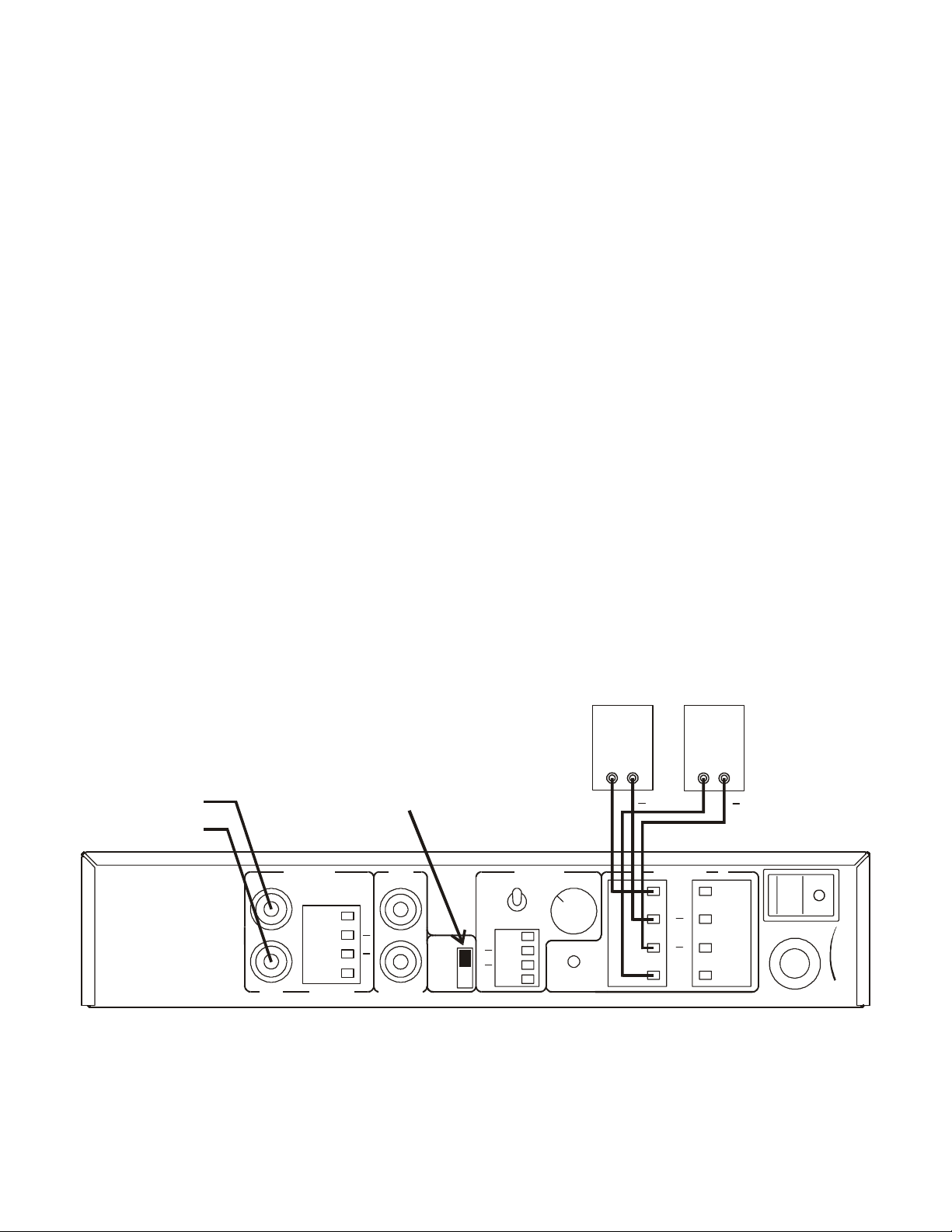
Fig. 3. LDS2/75 configured as a Stereo Amplifier with 4 ohm speakers.
4
Page 5
8 OHM
LEFT
SPEAKER
8 OHM
RIGHT
SPEAKER
8 OHM
LEFT
SPEAKER
8 OHM
RIGHT
SPEAKER
L
MODE SWITCH IS “STEREO” POSITION
AUDIO INPUT
R
INPUT
L
R
LINE SPEAKER
OUTPUT
+
L
R
+
(BUFFERED)
LINE
MODE
STEREO
MONO
BRDG
OUT
TRIGGER
MUSIC
12V
+
IN
+
LEVEL
LO HI
LDS LED
SEE
BELOW
12
SPEAKERS
+
L
R
+
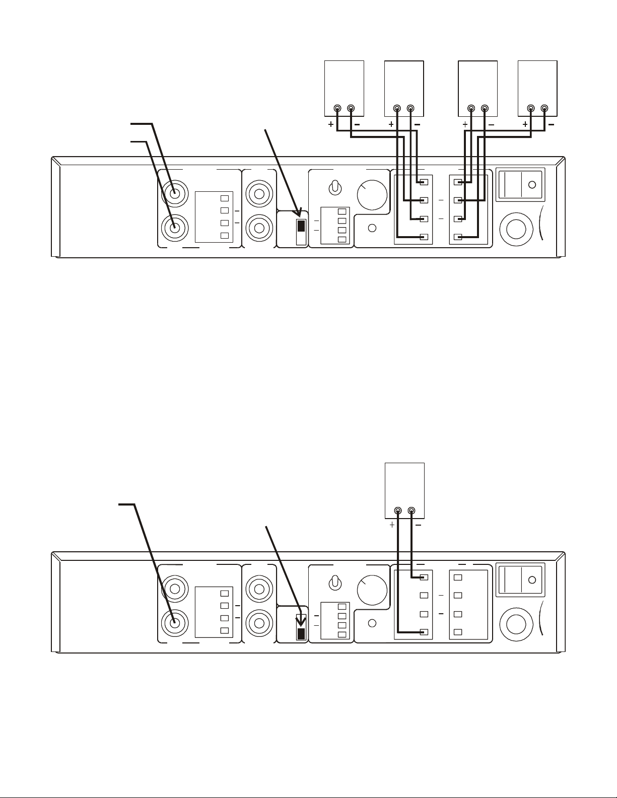
Fig. 3. LDS2/75 configured as a Stereo Amplifier with two pair of 8 ohm speakers.
POWER
120V 60H z 3A
275
TECHNOLOGIES, INC.
Sherbourn
SPEAKER
AUDIO INPUT
MODE SWITCH IS “BRDG” POSITION
INPUT
L
R
LINE SPEAKER
OUTPUT
+
L
R
+
(BUFFERED)
LINE
MODE
STEREO
MONO
BRDG
OUT
TRIGGER
MUSIC
12V
+
IN
+
LEVEL
LO HI
LDS LED
SEE
BELOW
12
SPEAKERS
+
L
POWER
R
+
120V 60H z 3A
Fig. 4. LDS2/75 Configured in Bridged Mode.
Use only the right channel input for bridged connection. Connect the “+” polarity of the speaker to the
“R+” speaker output, and the “-” polarity of the speaker to the “L+” speaker output.
5
Sherbour n
275
TECHNOLOGIES, INC.
Page 6
7-1/2” (190.5mm)
10-1/8”
(257mm)
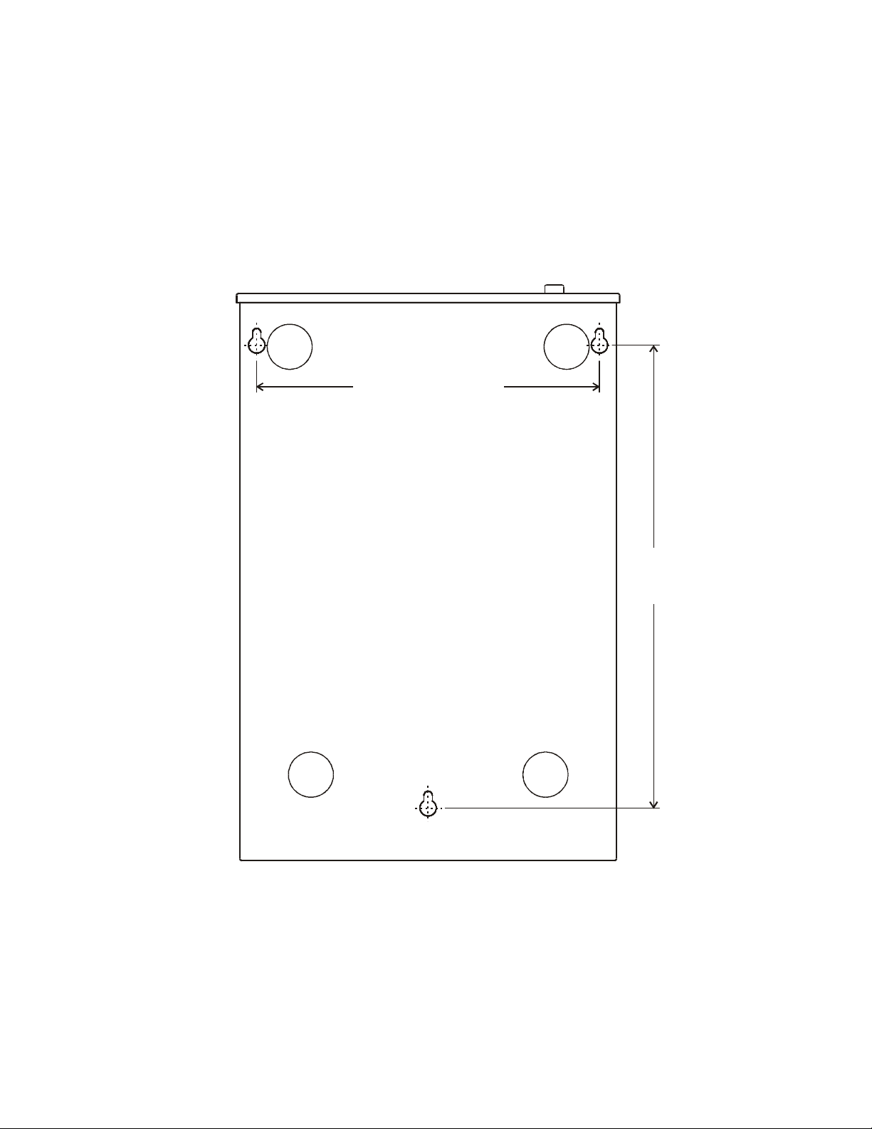
Fig.5. Location of bottom cover keyway slots used to mount
the LDS2/75 amplifier vertically against a wall with screws.
6
Page 7
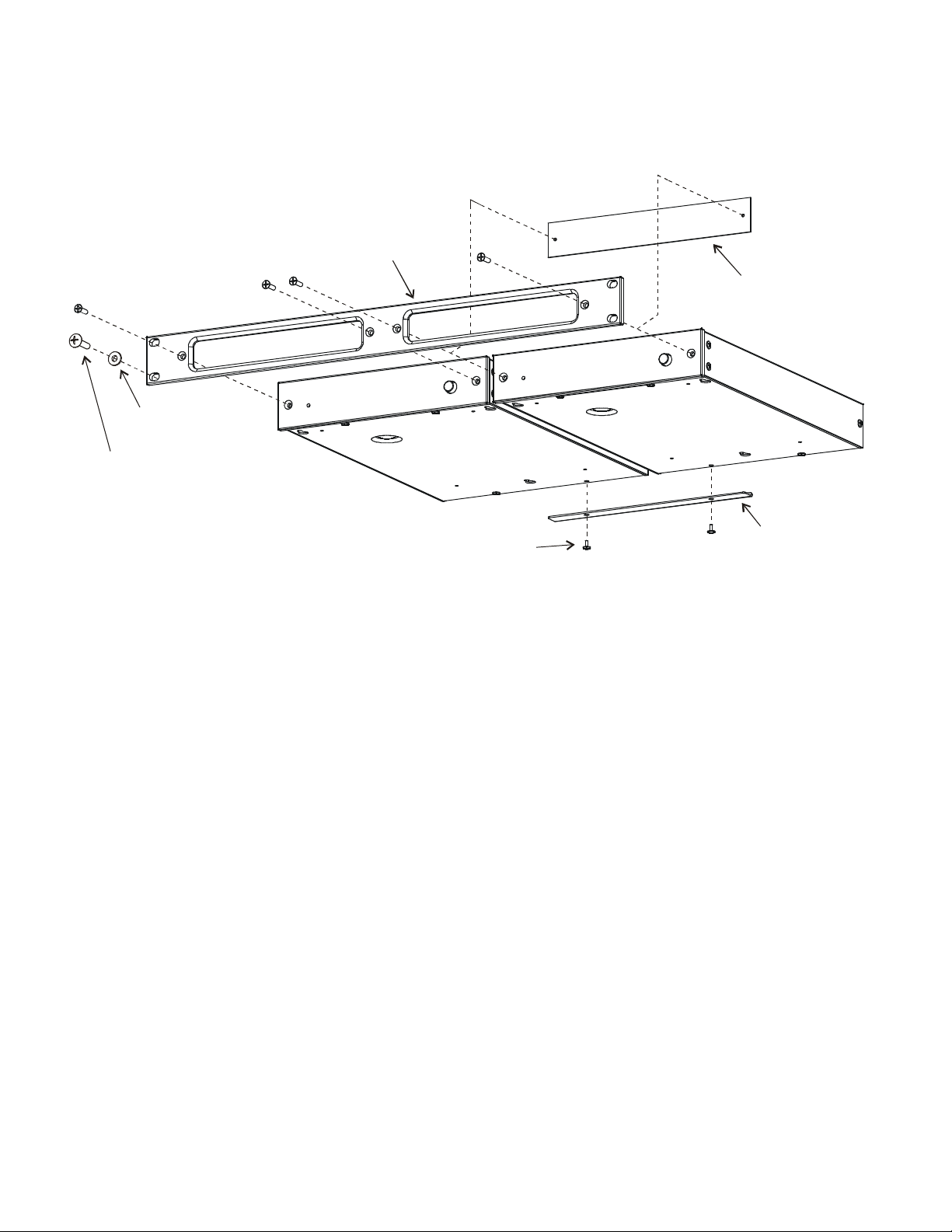
(1) RACK PANEL
(6) COVER PLATE
(ORDER
SEPARATELY)
NOTE 1
NOTE 3
(4) #10
WASHERS
(3) 10-32 x 1
SCREWS
AMPLIFIER
(5) EXISTING
SCREWS
1
AMPLIFIER
(2)
ALIGNMENT
BAR
2
NOTE 2
Fig. 6 Optional Rack Panel assembly
Note 1 - Remove two M4 flat head screws from front panel of amplifier and use them to fasten the amplifier
to the Rack Panel as shown above. The amplifier front panel is not removed.
Note 2 - Fasten the Alignment Bar (when two amplifiers are used) to the bottom cover of the amplifier using
the two screws already in place. This will hold the back of the amplifiers in alignment.
Note 3 - When only one amplifier is mounted to the Rack Panel, the second opening can be covered with a
Cover Plate that is not part of this kit.
Each Rack Mount Kit contains:
Item Qty Name To Mount
(1) 1 Rack Panel
(2) 1 Alignment Bar
(3) 4 10-32 x 1" truss head screws Rack Panel
(4) 4 #10 shoulder washers Rack Panel
(5) 2 existing amplifier screws Alignment Bar
Separately available from Sherbourn:
(6) 1 Cover Plate with mounting screws
7
Page 8

Three Year Limited Warranty
Subject to the terms and conditions stated below, Sherbourn Technologies, Inc. (Sherbourn)
warrants to the original owner that this model
LDS2/75 shall be free from defects in workmanship or materials for a term of three (3) years
from its date of purchase from an Authorized
Sherbourn Dealer. Transfer of this product by
its original owner (the ‘Owner’) will automatically terminate this Warranty regardless of
when occurring.
In the event of any defect covered by this warranty,
Sherbourn shall provide all parts, materials, and
labor necessary to restore the Product to its original specifications, and shall return the Product to
its owner at Sherbourn’s expense. In the alternative, Sherbourn may at its sole option either replace the Product without charge, or if its replacement is not commercially practicable or repair or
replacement cannot be accomplished within a reasonable time, Sherbourn may refund the purchase
price of the Product, subject where appropriate to
reasonable depreciation for actual use in accordance with applicable laws, in full satisfaction of
its warranty obligations.
Sherbourn’s sole obligation under this warranty
shall be to repair or replace the product, or at its
option refund the purchase price, as provided for
hereinabove. Sherbourn does not warrant
against, nor shall it be liable for, any of the following: removal or installation charges, shipping
expenses to Sherbourn or its authorized service
facility, loss of use, property damage of any kind,
or other incidental or consequential damage or
losses of any kind.
Note: Some states do not allow exclusion or limitation of consequential damages, so the foregoing
exclusions may not apply to you.
one other than Sherbourn or an Authorized
Sherbourn Service Facility; and Sherbourn shall
have no liability or obligation of any kind with respect to any of the foregoing losses types of failures.
To obtain service under this Warranty, the Owner
must first obtain from Sherbourn a Return Authorization Number, and must then, at the owner’s expense (i) arrange for any necessary de-installation
of the Product, and (ii) deliver or ship the Product,
properly packaged and clearly identified with the
Return Authorization Number, prepaid, and insured, to Sherbourn at the address shown below,
or to an Authorized Sherbourn Service Facility. In
addition, the Owner must provide evidence that the
Product is at the time of delivery within the scope
of this Warranty, by including the ORIGINAL
dated sales receipt with the Product when submitted for repair. Safeguard your original sales receipt,
as it may be required to validate Warranty coverage
The owner is solely responsible for payment of all
expenses for removing the Product from its installation, delivering it to Sherbourn or an Authorized
Sherbourn Service Facility, and reinstalling it following repair, as well as for any repairs made to
Products which are subject to the exclusions noted
above.
In order to learn the name and address of the nearest Authorized Sherbourn Service Facility, obtain
a Return Authorization Number and shipping instructions, or obtain answers to any other questions
you may have concerning this Warranty, you may
telephone Sherbourn between the hours of 9:00 am
and 5:00 pm Eastern Standard Time, Monday
through Friday at (978) 663-7385, or write to our
Service Department at Sherbourn Technologies,
Inc., 19-3A Sterling Road, North Billerica, MA
01862.
This warranty does not cover any of the following:
(a) cabinetry, trim, or other appearance items (except where they are defective at the time of original sale and the Product is delivered for repair
within the first thirty days (30) thereafter): (b) failures arising from accident, catastrophe, misuse,
neglect, or failure to properly connect and operate
the product in accordance with the accompanying
instruction: (c) failures arising from improper installation of the Product or incompatibility of other
components in the system of which the Product is
a part: (d) failures of any kind in products (i) which
have been purchased from other than Authorized
Sherbourn dealers, or (ii) which evidence any tampering, alteration, or attempted servicing by any-
8
This warranty gives you specific legal rights, and
you may also have other rights which vary from
state to state.
If this product has been purchased outside of the
United States of America, you should contact your
local dealer or distributor to determine the warranty
coverage provided in your country.
Sherbourn
Sherbourn Technologies, Inc.,19-3A Sterling Road,
North Billerica, MA 01862 Tel (978) 663-7385
Fax (978) 663-7389 Web www.sherbourn.com
R
 Loading...