

V4.0 2020-06
Shenzhen Yuejiang Technology Co., Ltd | China
ADDRESS: 9-10 Floors, Building No.2, Chongwen Garden, Nanshan i-Park, Nanshan District,
Shenzhen, China

Contents
I. Fast Assembly
1.1. Accessories List ..............................................................
II. Operation Panel
. Home Page ......................................................................
2.1
. 3-Point Leveling Interface ................................................
2.2
. File Directory Interface .....................................................
2.3
. Control Tools Interface .....................................................
2.4
2.5. 3D Print Functional Module Control Interface ..................
2.6. Zero Point Setting Interface .............................................
. X/Y/Z Motion Control Interface ........................................
2.7
2.8
. Other Settings Interface ..................................................
2.9
. Working Process Control Interface ..................................
. Switch Mixing Mode Configuration Interface .................
2.10
2.11
. Gradient Mixing Mode Configuration Interface .............
III. 3D Printing
3.1. 3-Point Leveling ..............................................................
3.2. Set the Zero Point .......................................................... 8
1
4
4
4
4
5
5
5
5
6
6
6
7
3.3. Install/Remove the Filament ............................
3.4. Use the Slicing Software ..................................
3.4.1. Install the Slicing Software .......................1010
3.4.3. Online Printing ...........................................
3.4.4. Configuration of Color Mixing Scheme ......1113
3.5. Power-Loss Resume ........................................ 16
3.6. Printing Control ................................................ 16
IV. Troubleshooting
4.1. 3D Printing Failure ............................................
4.2. Whole Machine Failure .....................................
4.3. 3D Print Functional Module Failure ..................
4.4. Maintenance of 3D Print Functional Module .... 20
Parameters
................................................................
9
103.4.2. Configuration for Initial Use .......................
18
18
19
21
Symbol Description
Description
Basic terms or reference information.
Note: Updated Firmwares, User Manuals, Softwares and Tutorial Videos will be uploaded to our official website www.dobot.cc
constantly, please use them for better experience. Any support, please contact us: mooz@dobot.cc.
Note
Important precaution: ignoring it may cause
malfunction of the machine and the
corresponding risk.
Warning
Important warning: rules must be strictly
observed, otherwise it may cause
machine breakdown and personal injury.
I
Fast Assembly
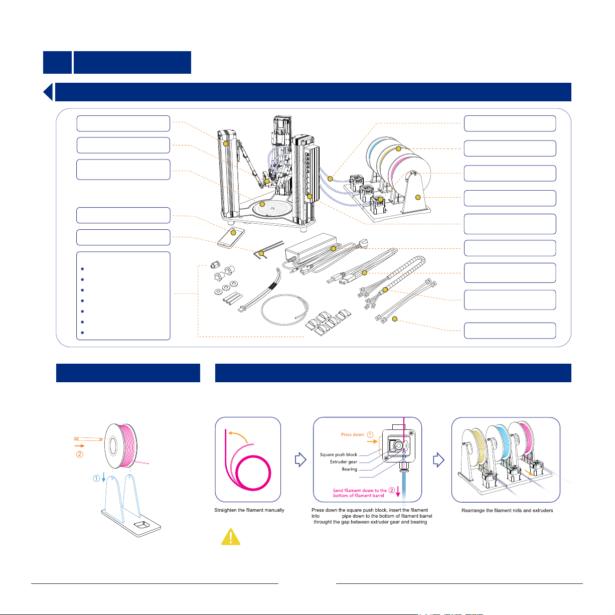
1.1 Accessories List
Identical Linear Actuators x 3
Printer Head Module x 1
Base + Main Control
Board + Heated Bed x 1set
LCD Touch Pad x 1
L-type Hex Screwdrive x 2
Spare Parts:
Quick Pipe Connector x 1
Nozzle x 2
Nozzle Sealing Gasket x 3
PTFE Pipe x 3
Temperature Sensor x 1
Bourbon Pipe x 1
Cable Clip x 5
1.1.1 Install the Filament Support
Set up the filament support, and place the
filament on it. As shown below
Bourdon Pipe x 3
250g PLA Filament x 3
Extruder x 3
Filament Support x 3
Printer Head Control Board
x 1
12V Power Adapter x 1
Usb 2.0 Cable x 1
(A-Male to B-Male)
Extruder Motor Power
Cable x 3
8-Core Cable x 2
1.1.2 Connect the Bourdon Pipe and Extruder
Run the filament through the extruder and insert one end of the bourdon pipe into pipe connector. Keep
feeding the filament until it extends out of the other end of the pipe for about 20~30mm.Place the
extruder on the filament support orderly after proper connecting.
Bourdon pipe
bourdon
Note:
In case the bourdon pipe and pipe connector need to be detached: Press down the plastic part of the connector and pull the
pipe out quickly (see the illustration above).
1
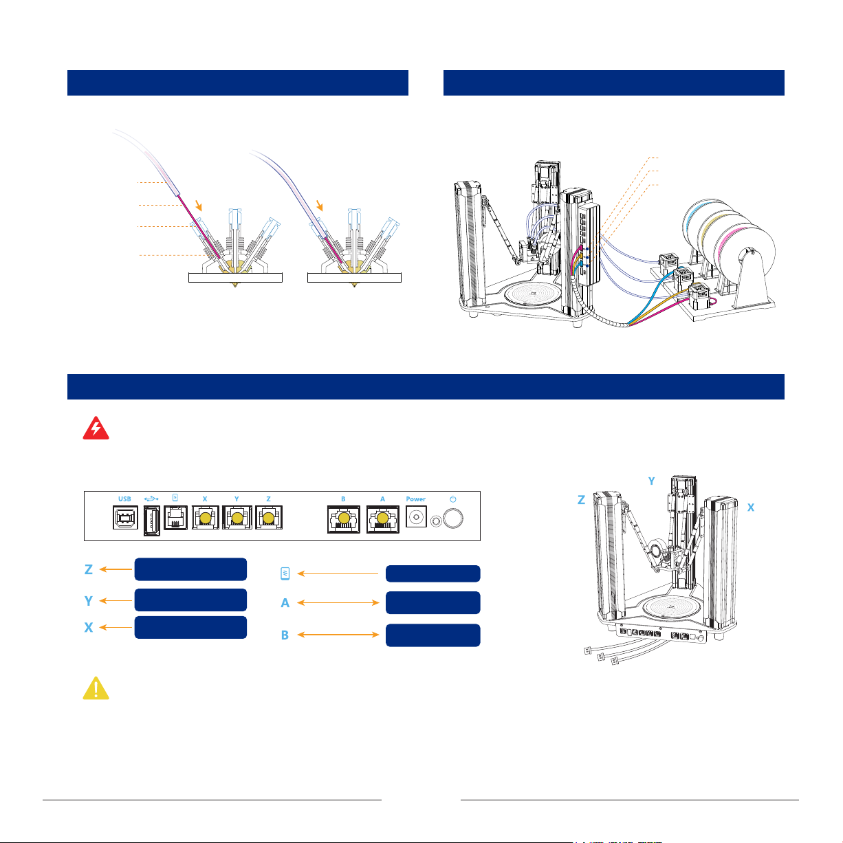
1.1.3 Connect the Bourdon Pipe to the Print Head
1.1.4 Install Extruder Motor Power Cables
Straighten out the filament, insert it into the print head. In the meanwhile,
feed the bourdon pipe into the pipe connector to clamp it.
Bourdon pipe
Filament
Quick pipe
connector
PTFE pipe
Connect the extruders to the corresponding ports of the printer head control
board with cables. As shown below:
Extruder port (For RED filament)
Extruder port (For YELLOW filament)
Extruder port (For BLUE filament)
1.1.5 Connect Cables to Main Control Board
Warning: Wrong connection of cables may cause burnout of control board! Hot-plug is strictly prohibited! Always make sure that all cables are plugged in place before power-on!
Plugging of cables during power-on status will cause malfunction!
Before power on the machine, please follow the chart below and connect all cables to the main control board correctly.
Linear actuator on left side
of main control board
Linear actuator on oppsite
side of main control board
Linear actuator on right side
of main control board
Note: The linear actuators are labeled with X, Y, Z based on mounting positions in the above drawing, which should be connected to the corresponding port on main control
board correctly!
8-core cable
8-core cable
LCD touch pad
Port A on printer
head control board
Port B on printer
head control board
2
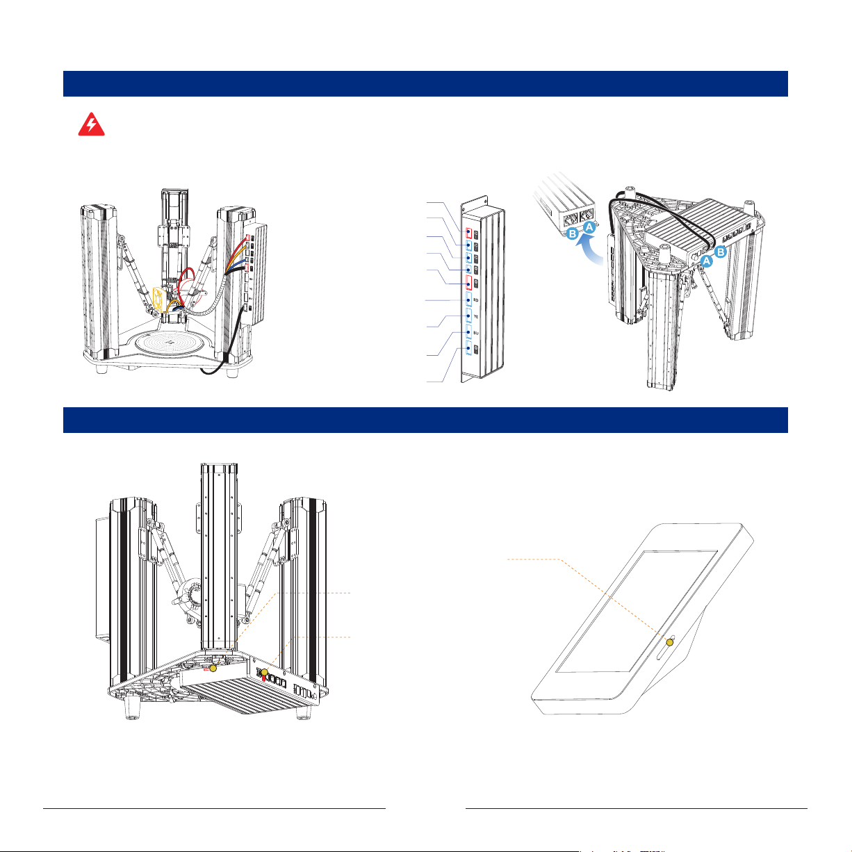
1.1.6 Connect Cables to Printer Head Control Board
Warning: Wrong connection of cables may cause burnout of control board! Hot-plug is strictly prohibited! Always make sure that all cables are plugged in place before power-on!
Plugging of cables during power-on status will cause malfunction!
Before power on the machine, please follow the chart below and connect all cables to the printer head control board correctly.
Blower fan (Red terminal) port
Filament barrel cooling fan port
Reserved fan port
Temperature sensor (White cable) port
Heating rod (Red terminal) port
Extruder port
(For RED filament)
Extruder port
(For YELLOW filament)
Extruder port
(For BLUE filament)
Heated bed port
1.1.7 External Interface Description
Touch pad SD interface: It is used
for updating the firmware of touch pad.
Main board SD interface: It is used
for updating the firmware of main
board and printing in offline mode.
U disk interface: It is used for
updating the firmware of main
board and printing in offline mode.
3
II Operation Panel
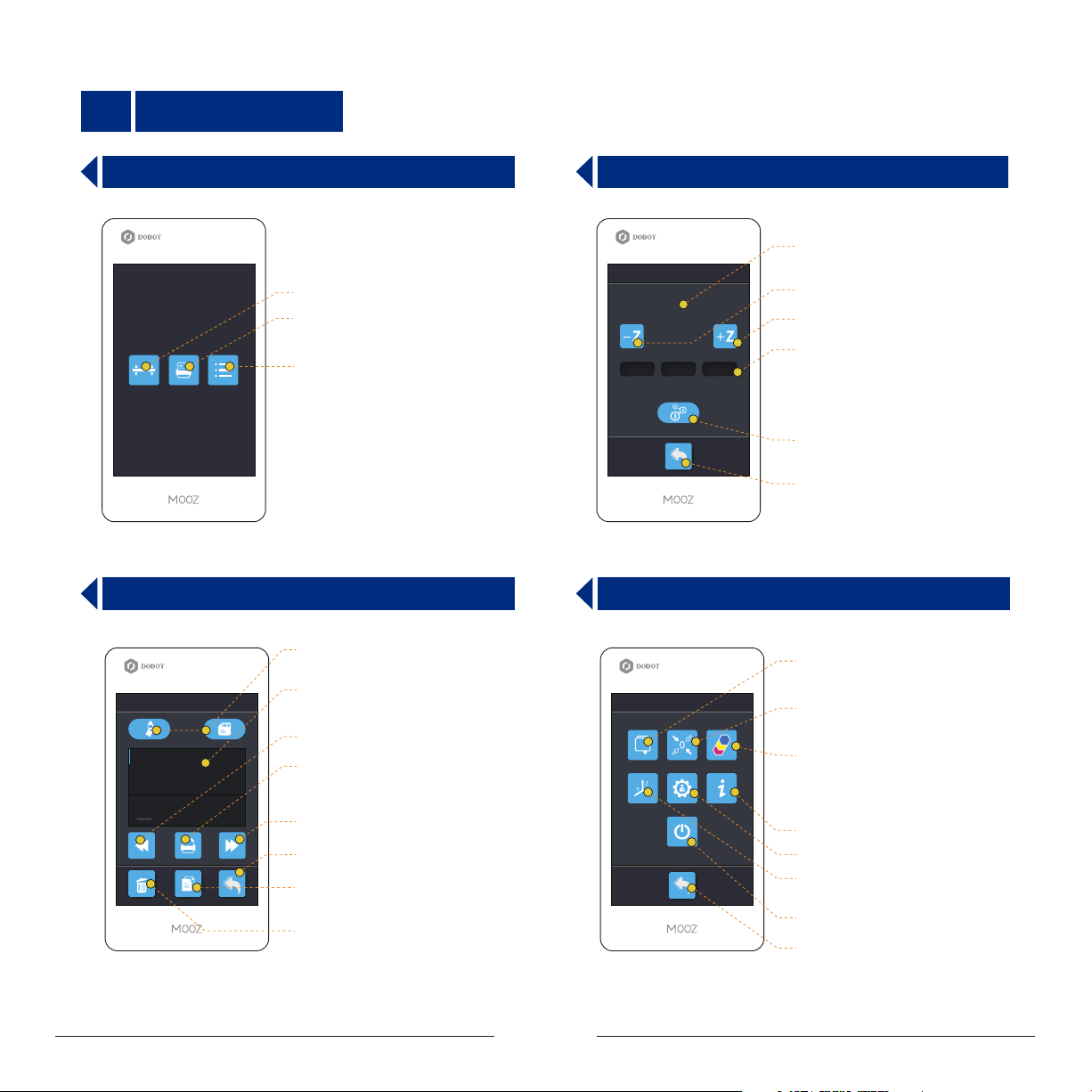
2.1 Home Page
Entrance to 3-point leveling interface
Entrance to le directory interface
Entrance to control tools interface
2.3 File Directory Interface
MicroSD card and U disk switching
buttons
Files
Model.gcode
........ .gcode
.........
.........
.........
Display supported Gcode les
in the current disk (microSD / U disk)
Page backward
File execution button: After selecting
the file, press the button to start printing
Page forward
Return
File copy: Copy the selected file to
the other disk
File delete: Delete the selected file
2.2 3-Point Leveling Interface
Display current coordinates
Leveling
Adjust nozzle downward
Z: 20
Y: 20X: 20
Adjust nozzle upward
Step distance switching buttons:
1 mm0.06 mm 10 mm
It should be used along with “-Z” and
“+Z” buttons, indicating the moving
distance of Z axis when the button
is pressed (0.06mm/1mm/10mm)
3-point leveling mode initiate/Point
recording button
Return
2.4 Control Tools Interface
Entrance to functional module
control interfaces
Control Tools
Entrance to zero point setting
interface
Entrance to color mixing
configuration interface
Machine information
Entrance to other settings interface
Entrance to X/Y/Z motion control
interface
Auto power-off
Return
4
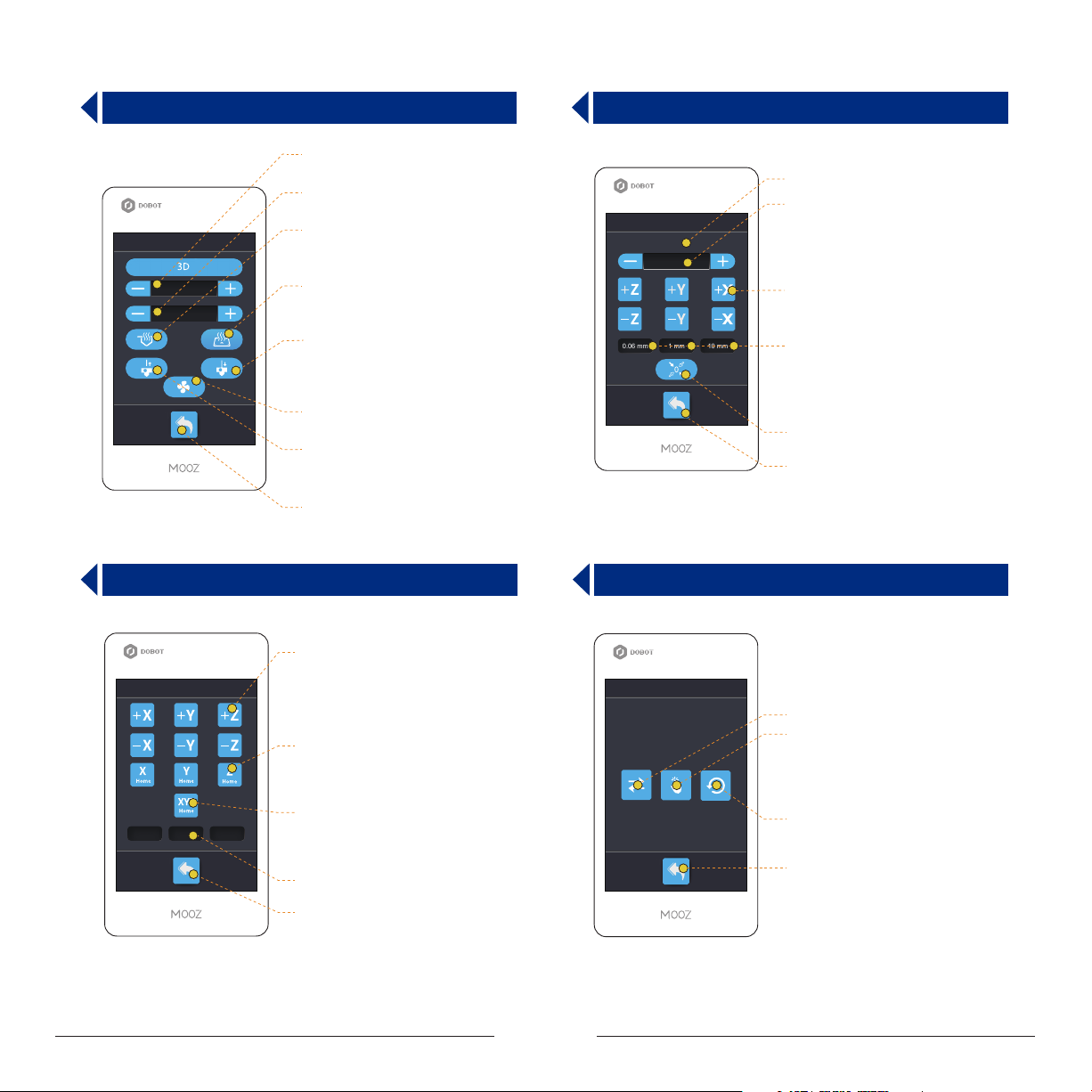
2.5 3D Print Functional Module Control Interface
Set nozzle preheat
target temperature
Set heated bed preheat
target temperature
Function
T:25℃/ 200℃
B:25℃/ 60℃
Preheat nozzle: For testing whether
the nozzle heating is normal, press
again to stop heating
Preheat heated bed: For testing
whether the bed heating is normal,
press again to stop heating
Filament feed button: For installing
filament and testing extrusion
performance, provided that the nozzle
is preheated to about 200ºC
Cooling fan switch: For detecting
whether the cooling fan is normal
Filament retraction button: For
removing filament, provided that the
nozzle is preheated to about 200ºC
Return
2.6 Zero Point Setting Interface
Display current coordinates
Fine tuning value for Z-axis zero point,
Zeroing
X: 20 Y: 20 Z: 20
0 mm
1 mm0.06 mm 10 mm
That is, when the zero point is higher,
it is set to a negative value, and when
the zero point is lower, it is set to a
positive value.
X/Y/Z motion control buttons
Step distance switching buttons:
It should be used along with motion
control buttons, indicating the moving
distance of linear actuators when the
button is pressed (0.06mm/1mm/10mm)
Zero point updating
Return
2.7 X/Y/Z Motion Control Interface
Control motion of X/Y/Z, the
corresponding operations will not
Move
1 mm0.06 mm 10 mm
change any settings
Reset X/Y/Z axis linear actuators
(Not available for MOOZ-3)
Reset all linear actuators, the
corresponding operations will not
change any settings
Step distance switching buttons
Return
2.8 Other Settings Interface
Settings
Switch languages
Calibrate the LCD touch screen
Restore factory settings
Return
5
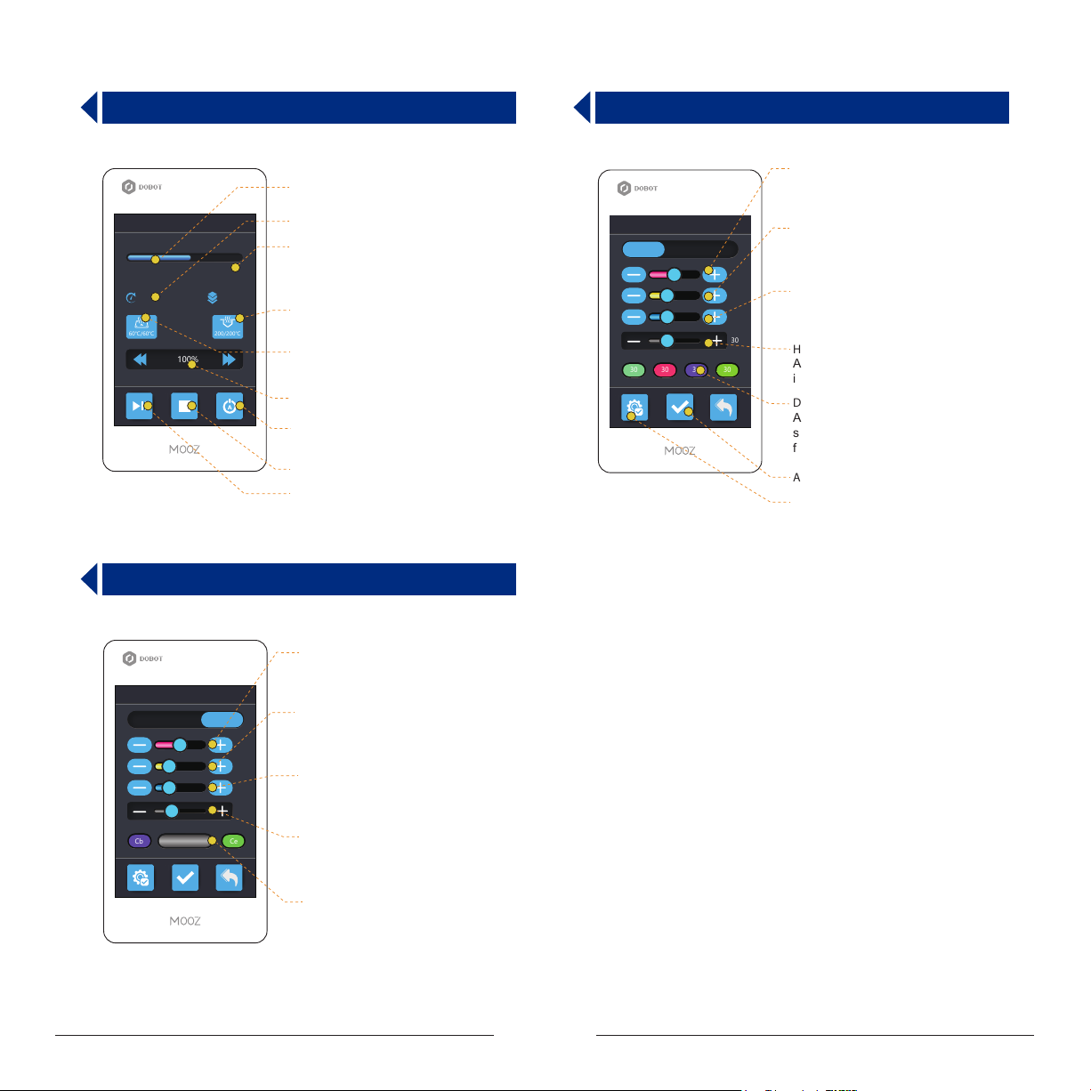
2.9 Working Process Control Interface
Display execution progress of
current le
X: 20
60℃/60℃
00:00:20
Printing...
Model1.gcode
Y: 20
100%
Z: 20
62%
200/200℃
Display time elapsed
Display current coordinates
Display current/target nozzle
temperature
Display current/target heated
bed temperature
Real-time working speed control
buttons
Auto power-off
Abort the process
Pause/Continue the process
2.11 Gradient Mixing Mode Configuration Interface
2.10 Switch Mixing Mode Configuration Interface
Red lament percentage:
Adjustment range: 0~100, 0 means
red filament will not be used to mix
Switch
Mixing
Gradient
50
25
25
30
3030 30 30
Yellow lament percentage:
Adjustment range: 0~100, 0 means
yellow filament will not be used to mix
Blue lament percentage:
Adjustment range: 0~100, 0 means
blue filament will not be used to mix
Height adjustment:
Adjustment range: 1~100, default
is 30mm
Display current switching scheme:
A maximum of 4-color switching is
supported, you can set different height
for each color
Applied congured mixing scheme
Default color mixing scheme
Mixing
Switch
Cb Ce
Gradient
30
Red lament percentage:
Adjustment range: 0~100, 0 means
red filament will not be used to mix
Yellow lament percentage:
50
25
25
30
Adjustment range: 0~100, 0 means
yellow filament will not be used to mix
Blue lament percentage:
Adjustment range: 0~100, 0 means
blue filament will not be used to mix
Gradient cycle:
Adjustment range: 1~100, default
is 30mm
Display current mixing scheme:
Cb is cycle begin color, and Ce is
cycle end color
6
 Loading...