

Page 1
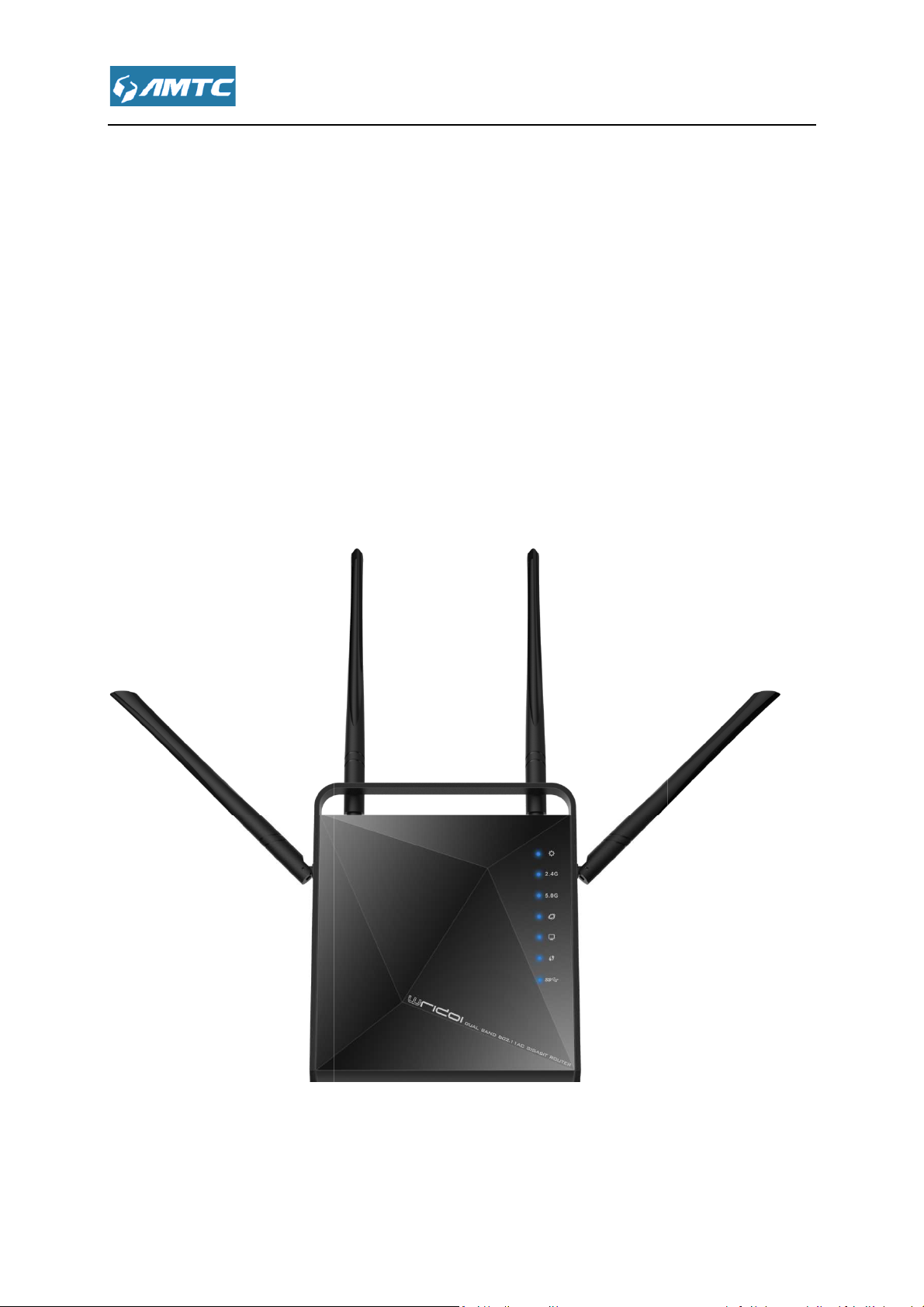
1200M Wireless Router
WR1201
User Guide
Page 2

Changes or modifications to this unit not expressly approved by the party responsible for
compliance could void the user’s authority to operate the equipment.
equipment has been tested and found to comply with the limits for a Class B digital
pursuant to part 15 of the FCC Rules. These limits are designed to provide reasonable
against harmful interference in a residential installation. This e
radiate radio frequency energy and, if not installed and used in accordance with the
may cause harmful interference to radio communications. However, there is no
interference will not occur in a
interference to radio or television reception, which can be determined by turning the
and on, the user is encouraged to try to correct the interference by one or more of
Reorient or relocate the receiving antenna.
Increase the separation between the equipment and receiver.
Connect the equipment into an outlet on a circuit different from that to which the receiver
or an experienced radio/ TV technician for help.
FCC RF Radiation Exposure Statement:
This device complies with Part 15 of the FCC Rules. Operation is subject to the following two
this device may not cause harmful interference
must accept any interference received, including interference that may cause undesired
“FCC RF Radiation Exposure Statement Caution: To maintain compliance with the FCC’s RF
exposure guidelines, place the product at least 20cm from nearby perso
quipment generates,
particular installation. If this equipment does cause
FCC STATEMENT
Warning:
Note:This
device,
te the equipment.
protection
uses and can
instructions,
guarantee that
harmful
equipment off
the following measures:
•
•
•
connected.
• Consult the dealer
llation. This e
eceiver.
se
is
conditions:
1)
2)this device
operation.
m from nearby persons.”
Page 3

2AHVHWR1201
This device complies with part 15 of the FCC Rules. Operation is subject to the following two
This device may not cause harmful interference.
This device must accept any interference received, including interfer
0359
n a domestic environment,
which case the user may be required to take adequate measures.
The manufacturer is not responsible for any radio or TV interference caused by unauthorized
modifications to this equipment.
2) To avoid unnecessary radiation interference, it is recom
DECLARATION OF CONFORMITY
Co., L
with the essential requirements and other relevant provisions of Directive 1999/5/EC.
The declaration of conformity may be consult at
ADAPTER INFORMATION
MOSO SWITCHING ADAPTER
18A
Input:100~240V 50/60Hz 0.6A Max.
ence that may cause
this product may cause radio interference,
This device complies with EU
1200M Wireless Router
FCC ID :
conditions:
1)
2)
undesired operation.
CE Mark Warning
this is a Class B product i
1999/5/EC.
e measures.
in
NOTE:
1)
Hereby, [Shenzhen MTC
Import / manufacture Name:
Import / manufacture Address:
is recom
TD], declares that this [
] is in compliance
Model:MSP-C15001C12.0-
Output:DC 12V-1.5A
-US
Page 4

Important Safety Instructions
Don’t disassemble the product, or make repairs yourself.
2. Do not operate this product near water.
3. Do not place or operate this product near a radiator or a heat register.
Do not expose this product to dampness, dust or corrosive liquids.
duct or disconnect it
6. Do not block the ventilation slots of this product, for insufficient airflow may harm it.
. When plugging this product into a socket, make sure th
ere is no gas leakage.
Place the connecting cables properly so that people won’t stumble or walk on it.
This product should be operated from the type of power indicated on the marking label. If you
sure of the type of power available, consu
he
liquid has been spilled on the product
s been exposed to rain or water
If you need service, please
socket during a lightning or a thunderstorm.
at the electrical socket is not
service personnel for
). The Storage temperature is
1.
us.
4.
5. Do not connect this pro
7
and that th
8.
9.
are not
10. Unplug this product from t
from a
lt the qualified technician.
mains and refer the product to qualified
contact
damaged,
the
following conditions:
If
If the product ha
11. The Operating temperature
(-40℉~158℉).
is 0℃~40℃(32℉~104℉
-40℃~70℃
Page 5

................................
................................
................................
................................
................................
Chapter 2 Connecting Mechanism
................................
................................
2.3 Configure PC TCP/IP Settings
................................
................................
................................
Introduce to Layouts
3.4Commonly used Web page elements
Chapter 4 Features & Configurations
................................
................................
................................
................................
................................
................................
................................
................................
4.2.3 MAC Address Clone
................................
................................
................................
................................
................................
................................
................................
................................
................................
................................
................................
................................
................................
................................
................................
................................
.............................
................................
................................
................................
................................
................................
................................
................................
................................
...............................
................................
................................
CONTENTS
Important Safety Instructions
Chapter 1 Product Overview
1.1 Introduction
1.2 LED Indicator
1.3 Physical Interfaces
2.1 Preparation
2.2 Hardware Connection
Chapter 3 Log in to the Router
3.1 Log in
3.2 Web Page
3.3 Web page
................................
................................
................................
................................
................................
................................................................
................................
................................
................................
................................
................................................................
................................
................................
............ 4
............ 8
......................... 8
...................... 8
.............. 9
. 10
........................ 10
........ 11
........................... 11
....... 15
. 15
.......................... 16
........................ 17
4.1 System Status
4.1.1 System Status
4.1.2 WAN Status
4.1.3 LAN Status
4.1.4 Wireless Status
4.2 Network Settings
4.2.1 LAN Setting
4.2.2 WAN Setting
4.3 WLAN Settings
4.3.1 Basic Settings
Introductions
................................................................
................................
................................
................................
................................
................................
................................
................................
................................
................................................................
................................
................................
.......................... 18
19
................... 19
......... 19
............ 20
.............. 21
....... 21
............... 23
............. 23
........... 24
27
.................. 29
......... 29
Page 6

4.3.2 Security Settings
vanced Settings
................................
................................
tion Status
................................
................................
................................
................................
................................
................................
................................
................................
t & Binding
................................
................................
................................
................................
................................
................................
................................
................................
................................
................................
................................
................................
................................
................................
................................
................................
................................
................................
................................
................................
................................
................................
................................
................................
................................
................................
................................
................................
...............................
................................
................................
................................
................................
................................
................................
................................
................................
................................
................................
................................
................................
................................
................................
................................
4.3.3 Ad
4.3.4 WPS Settings
4.3.5 Access Control
4.3.6 Connec
4.4 USB Setting
4.4.1 Device Sharing
4.4.2 Media Server
4.4.3 Print Server
4.4.4 User Accounts
4.5 IPTV Settings
4.6 DHCP Server
4.6.1 DHCP Server
................................................................
................................................................
................................
................................
................................................................
................................
................................
................................
................................
................................
................................
................................
................................
..... 31
.. 34
.......... 35
........ 36
.. 38
....................... 38
....... 38
........... 39
............. 40
......... 40
.................... 41
..................... 41
.......... 41
4.6.2 DHCP Lis
4.7 Virtual Server
4.7.1 Port Range
4.7.2 DMZ Settings
4.7.3 uPnP Settings
4.8 Security Settings
4.4.1 Client Filter
4.4.2 URL Filter
4.4.3 MAC Filter
4.4.4 Prevent
4.4.5 Remote WEB
4.4.6 WAN Ping
4.9 Routing Settings
................................................................
................................
................................
................................
................................
................................
................................
................................
................................
................................
................................
................................
................................
43
..................... 44
.............. 45
.......... 46
......... 47
............... 48
.............. 48
................ 50
............... 51
.................... 52
.......... 52
................ 54
................ 55
4.10 Triffic Control
4.11 System Tools
4.11.1 Time Settings
................................
................................
................................
................... 55
................... 57
........ 57
Page 7

................................
4.11.3 Backup & Restore
irmware Update
4.11.5 Restore to Factory
................................
word
................................
................................
1 Configure PC TCP/IP Settings
................................
................................
................................
................................
................................
................................
................................
................................
................................
................................
................................
................................
.............................
................................
................................
................................
................................
4.11.2 DDNS
4.11.4 F
4.11.6 Reboot
4.11.7 Change Pass
4.11.8 System Logs
Appendix ................................
Windows 7
Windows XP
2 FAQs
3 Factory Default Settings
................................
................................................................
................................................................
................................................................
................................
................................................................
................................
................................
................................................................
................................
................................
................................................................
................................
.................... 58
. 59
.. 60
61
................... 62
. 63
......... 63
......... 65
65
....................... 65
..................... 71
.... 75
....... 76
Page 8

Overview
1200M Wireless Router
bandwidth
set up wireless password
USB function, you can save data in USB disk or read data from it.
with IEEE 802.11
Provide one USB3.0 port supporting file sharing and print server.
-
.
Support Client Filer, MAC Filer, URL Filer.
remote web management
Support DDNS, port forwarding,
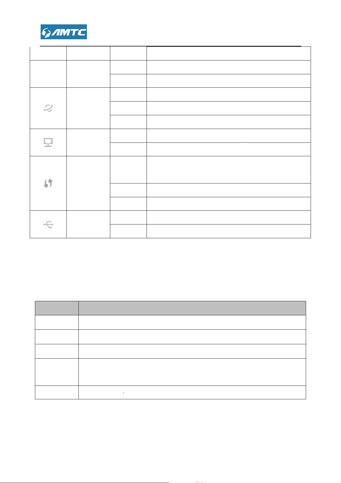
The LED indicator displays information about the device’s status.
Status
Blinking
Solid
Blinking
upports simultaneous 2.4GHz and 5GHz connections
tic IP three modes to
The router also support for
PSK authentication, TKIP/AES encryption security.
is not booted
transfer
Chapter 1 Product
1.1 Introduction
WR1201
1200Mbps of total available
Internet. You can
Complies
Provide internally installed
Provide WPA/WPA2, WPA
Support access control.
s
, supports for DHCP, PPPOE, sta
and Internet filler function.
a/an/ac and 802.11b/g/n.
TF card function.
PSK/WPA2-
for
Support firmware upgrade
Support
Use built-in antenna.
1.2 LED Indicator
LEDs Names
DMZ Host, UPNP.
Indications
The router is booting or upgrading.
System LED
The router has booted.
Off Power is off or the router
2.4G
2.4G LED
2.4G wireless is on and have data
.
red.
Page 9
There are physical interfaces on this
Blinking
Solid
Blinking
Blinking
Blinking
Solid
Solid
connected to power socket
onnected Internet with
4)
Press the button to connect another router through the WPS
Press the button more than
connects to a USB
transfer
The Internet port is connected but inaccessible.
and accessible
There is device(s) connected to the Ethernet (1/2/3/4) port(s
No any device is connected to the Ethernet (1/2/3/4) port.
WPS button on the router is pressed, and the
connect a wireless device to its network via WPS.
The connection via WPS is successful.
port.
port.
(output 12V,
store to its factory default
printer
Off 2.4G wireless is disabled.
5.0G
The 5G wireless is on and have data
5G LED
Off The 5G wireless is disabled.
Internet LED
Ethernet LED
WPS LED
USB LED
The Internet port is connected
Off The Internet port isn’t connected.
Off
Off The connection via WPS fails.
Off No device is connected to the USB
The device is connected to the USB
red.
.
).
router is trying to
1.3 Physical Interfaces
Item
Supply hub A Supply hub
WAN Port A port c
LAN Port Ports (1, 2, 3,
WPS/RST
Button
USB Port The USB port
router
Description
with power adapter
reticle.
connected your computer.
10 seconds, the device will re
storage device or a USB
1.5A).
.
.
Page 10

Connecting Mechanism
Before you start the installation process, you need to prepare the following:
Find it in your package
Find it in your package.
Should have a installed IE8 or higher browser
O
1. Ethernet Cable from the incoming Internet side: This is provided by your ISP
2. ISP Information: Your Internet service provider (IS
you with all of the information needed to connect to the Internet. If you cannot
locate this information, ask your ISP to provide it
If your ISP uses a PPP
and password
If you use
If your ISP gives you a fixed or static IP address for Internet
connection, you will need to gather the following information:
1) IP Address
2) Subnet Mask
3) Gateway
4) DNS Server
5) Alternate DNS
WISP Internet Access:
1. Remote AP's SSID, MAC address, security mode, cipher type and security
2. Internet connection information provided by the remote AP
3. Ethernet Cable: This can be found in the product package. You will need it
P) should have provided
E Internet connection, you will need ISP login name
a DHCP Internet connection, no information is needed
Chapter 2
2.1 Preparation
Item Description
Router
Power adapter
PC
DHCP, PPP
.
.
E or Static IP Internet Connection Type:
Gather ISP
Information
O
Server (Optional)
key
Page 11

to connect your PC to this device
------------------------------------------------------------------------------------
Before connecting, please make sure that you can surf the internet in your
----------------------------------------------------------------------------------------------------------------------------
what
Use another reticle to connect your
ower
PC TCP/IP Settings
Before you log in to the router, please
automatically" and "Obtain DNS server address automatically" from the device.
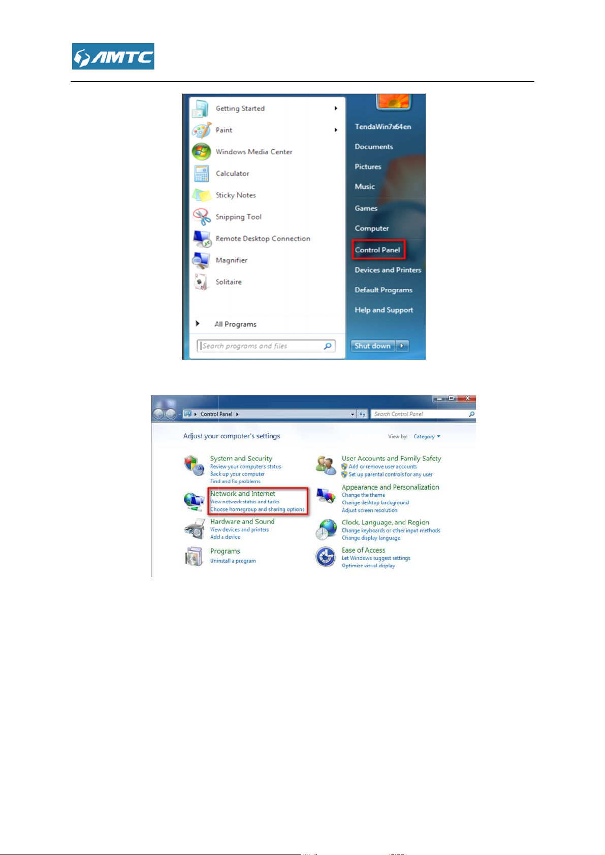
> Control Panel
-------------------------------
the router's WAN port
outer
. And the hardware connection is finished.
"Obtain an IP
2.2 Hardware Connection
Note
reticle provided by ISP.
①
① Please connect reticle
①①
②
②
②②
③
③ Connect the router’s p
③③
2.3 Configure
①
① Click Start -
①①
you ever connected to the computer with
computer
adapter
Ethernet port
with the r
make sure your computer set to
.
computer to use the
-----
.
’s any LAN port.
address
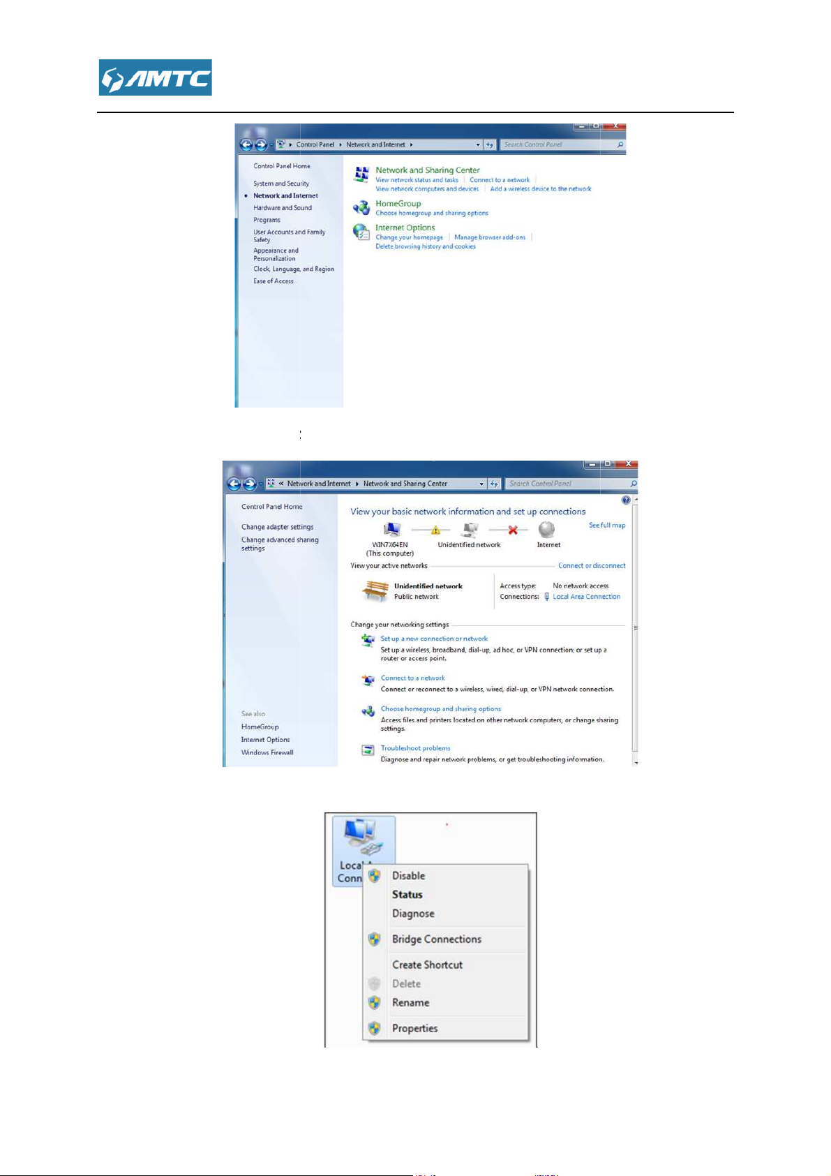
Page 12
Network and Internet
Sharing Center
②
② Click
②②
③
③ Click Network and
③③
.
.
Page 13
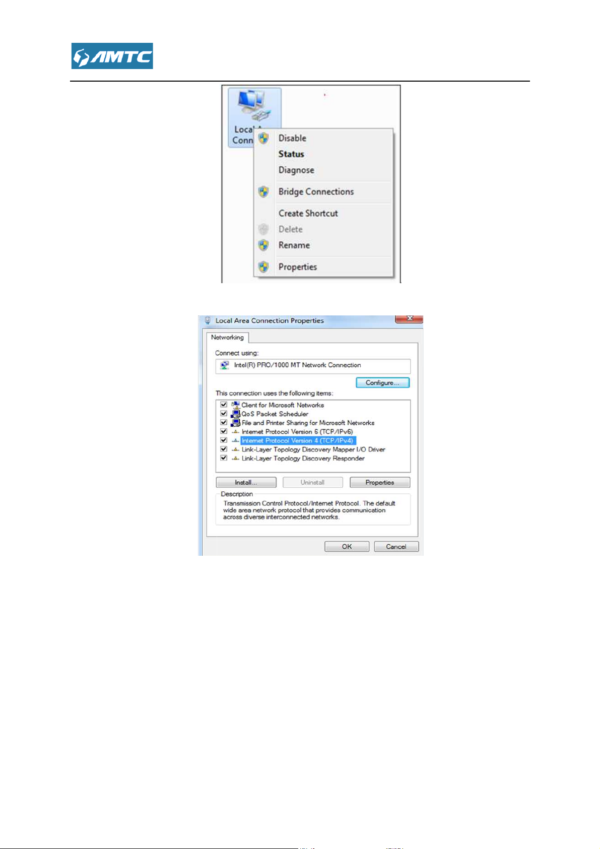
④
Change adapter settings
Local Area Connection
Internet Protocol Version 4 (TCP/IPv4)
④ Click
④④
.
⑤
⑤ Click
⑤⑤
⑥
⑥ Select
⑥⑥
and select Properties.
and click Properties.
Page 14
⑦
Obtain an IP address automatically
Local Area Connection Properties
to save your settings
⑦ Select
⑦⑦
and click OK
⑧
⑧ Click OK on the
⑧⑧
window
Page 15
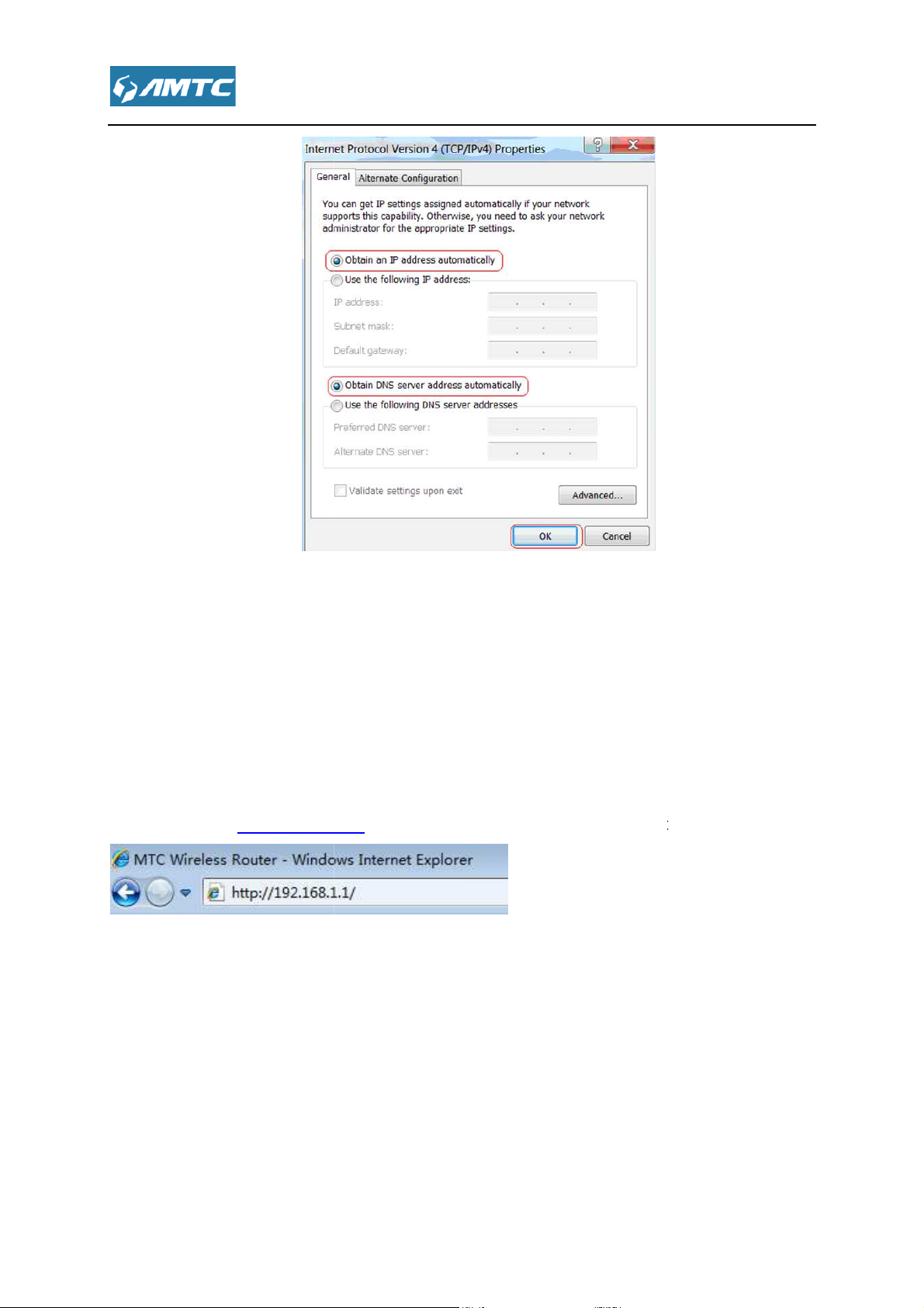
the Router
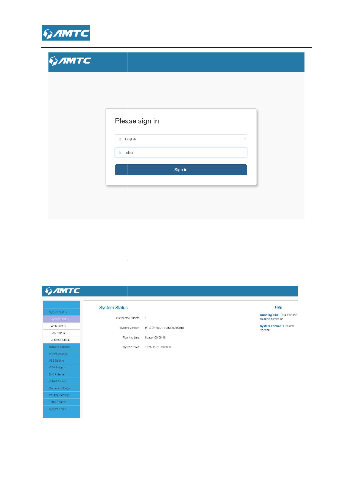
To access the Router’s Web
http://192.168.
automatically display the login page, please enter the co
Click the
based Utility, launch a web browser such as Internet Explorer or
Press “Enter”.
Chapter 3 Log in to
3.1 Log in
Firefox and enter
The system will
(default password is admin).
-
1.1 in your browser's address bar.
“Sign in” button or press “Enter”.
rrect the password
Page 16
,t
. You can view
. You can view
3.2 Web Page
After clicking the “Sign in”
modify settings here
he system will display the router Web page
and
Page 17
to Layouts
navigation
navigation
configuration area
help information area
configuration area
function menu
The user can
easily select function menu in the navigation bar
in the configuration area
settings here.
current page
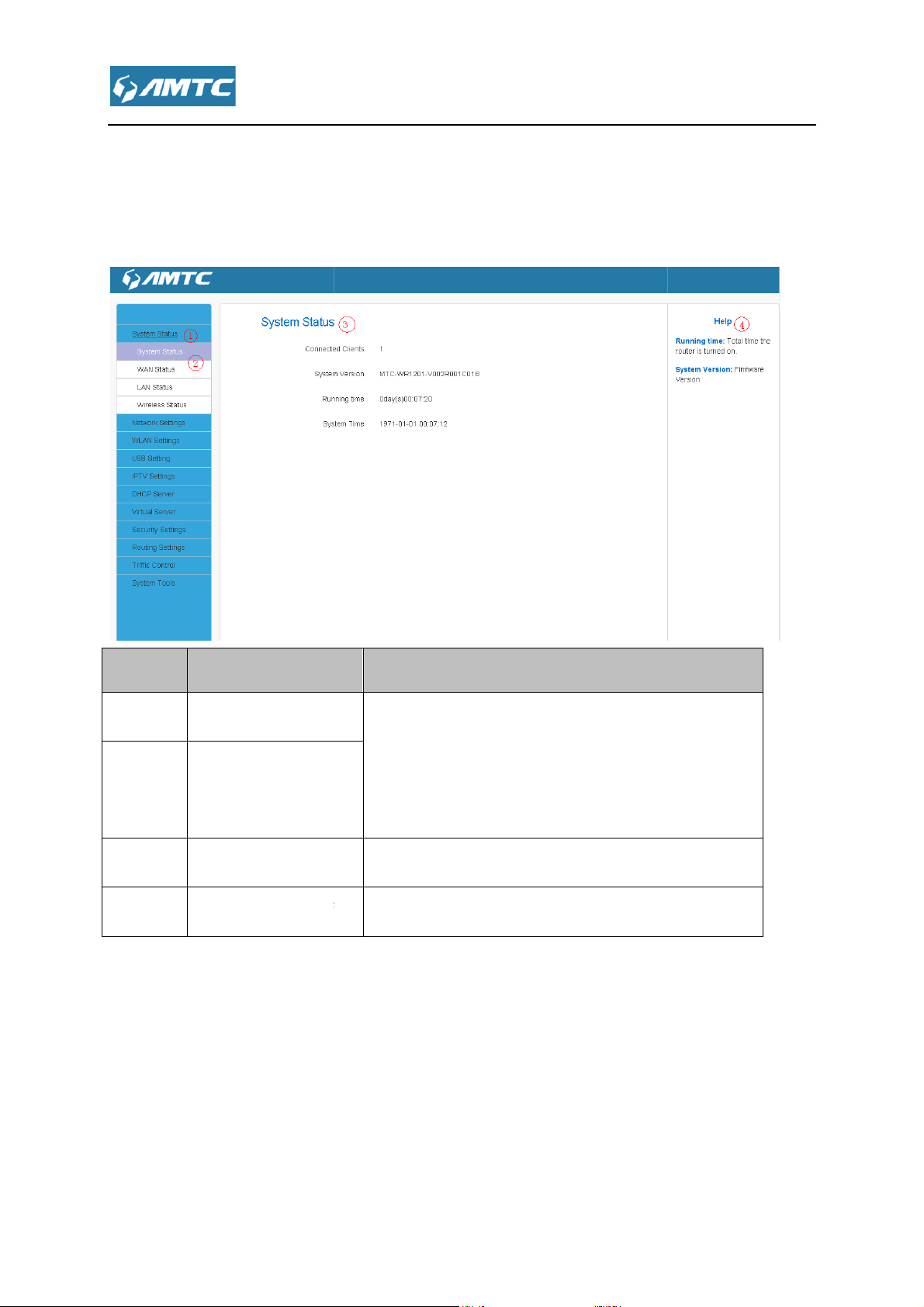
3.3 Web page Introduce
The Web page consist of
information area.
Primary & secondary navigation,
and help
NO Name
1
○
2
○
3
○
4
○
Primary
secondary
Introductions
The navigation bar organize
page in the form of a navigation tree.
results will display
The user can configure and view
Show help information of the
of Web
. The
.
.
Page 18
Note
Change the resolution of the screen the help information may become
you want to refer the help information please click the symbol.
Commonly used Web page elements
Introductions
To release the WAN IP address information
o obtain the WAN IP
o save the current configuration page
o cancel the current
settings
o delete the corresponding rules
o refresh the current page
Release
Renew
Save
Cancel
Add
Delete
Refresh
?
3.4
Common elements
“
” as above shown, if
Introductions
T
T
T
.
address information again.
.
configuration page.
To add
T
T
to the list
display content.
.
Page 19
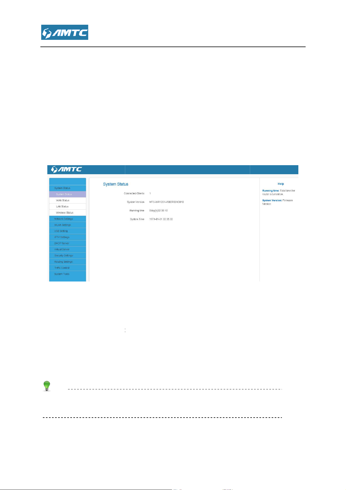
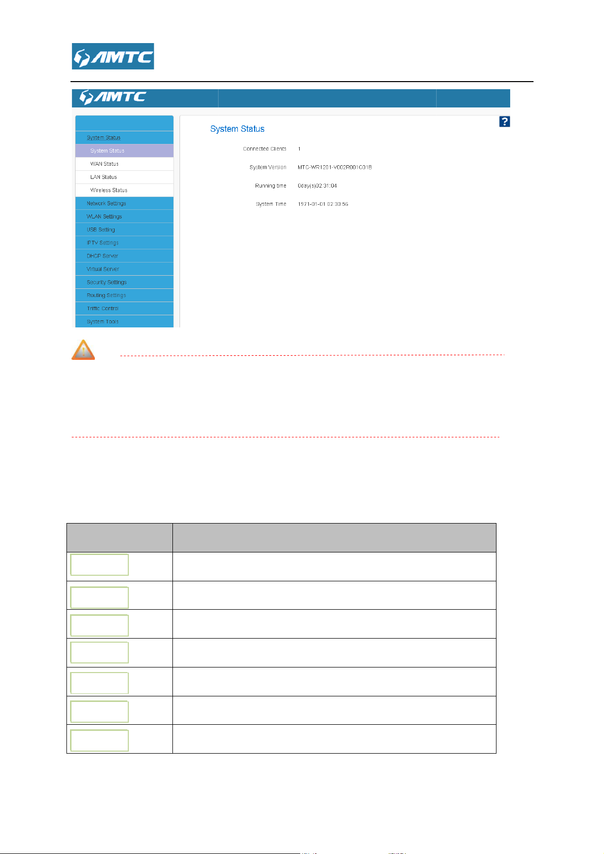
Features & Configurations
, enter the system status web page, in this page you can see the
WAN Status
s Connected Clients
displays the number of DHCP clients.
Firmware Version
Displays the time duration indicating how long the router has been up since
startup. Up time is recounted and renewed upon poweroff
Current system time on this device. The device automatically synchronizes the
system time with Internet time servers.
Running time is total time the
, System Time.
Chapter 4
4.1 System Status
Click “System Status”
“SystemStatus”, “
4.1.1 System Status
This page display
” ,”LAN Status”, “Wireless Status”.
, System Version, Running Time
Parameters Specification:
Connection Clients:
System Version:
Running Time:
System Time:
Tips
.
.
router is turned on
Page 20
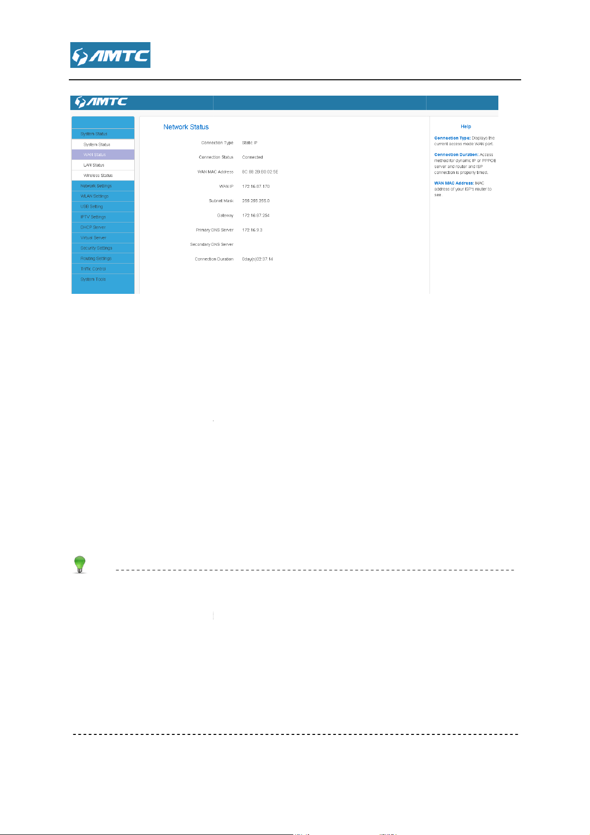
displays the current access mode
The network connection status.
MAC address of your ISP's router to see
IP address obtained from ISP.
Obtained from ISP.
Obtained from ISP.
Obtained from ISP.
Obtained from ISP.
Access method for dynamic IP or PPPOE server and router and ISP
connection is properly timed.
IP/Subnet Mask/Gateway/Primary DNS Server/Secondary
of information appears only if the router successfully connects to Internet via a PPPoE or DHCP
(dynamic IP) connection. However if you connect the router to Internet with static IP settings
provided by your ISP, these fields will di
successfully connects to the Internet or not.
If nothing appears in the secondary DNS server field, there is no available secondary DNS server
DNS Server:
splay the settings you entered whether the router
4.1.2 WAN Status
Parameters Specification:
Connection Type:It
Connection Status:
WAN MAC Address:
WAN IP:
Subnet Mask:
Gateway:
Primary DNS Server:
Secondary DNS Server:
Connection Duration:
Tips
WAN
of WAN port.
.
This types
Page 21

The Router’s LAN IP
The Router’s LAN subnet mask.
the status of DHCP server.
The router
The default IP address is 192.168.1.1.
The default Subnet mask value is 255.255.255.0
If the router as a DHCP server, here shown as enabled.Otherwise disabled
This page shows the information of 2.4G Wireless and 5G Wireless.
4.1.3 LAN Status
Parameters Specification:
IP Address:
Subnet Mask:
DHCP Server:
LAN MAC Address:
Tips
4.1.4 Wireless Status
Address (not your PC’s IP address).
’s physical address.
Page 22
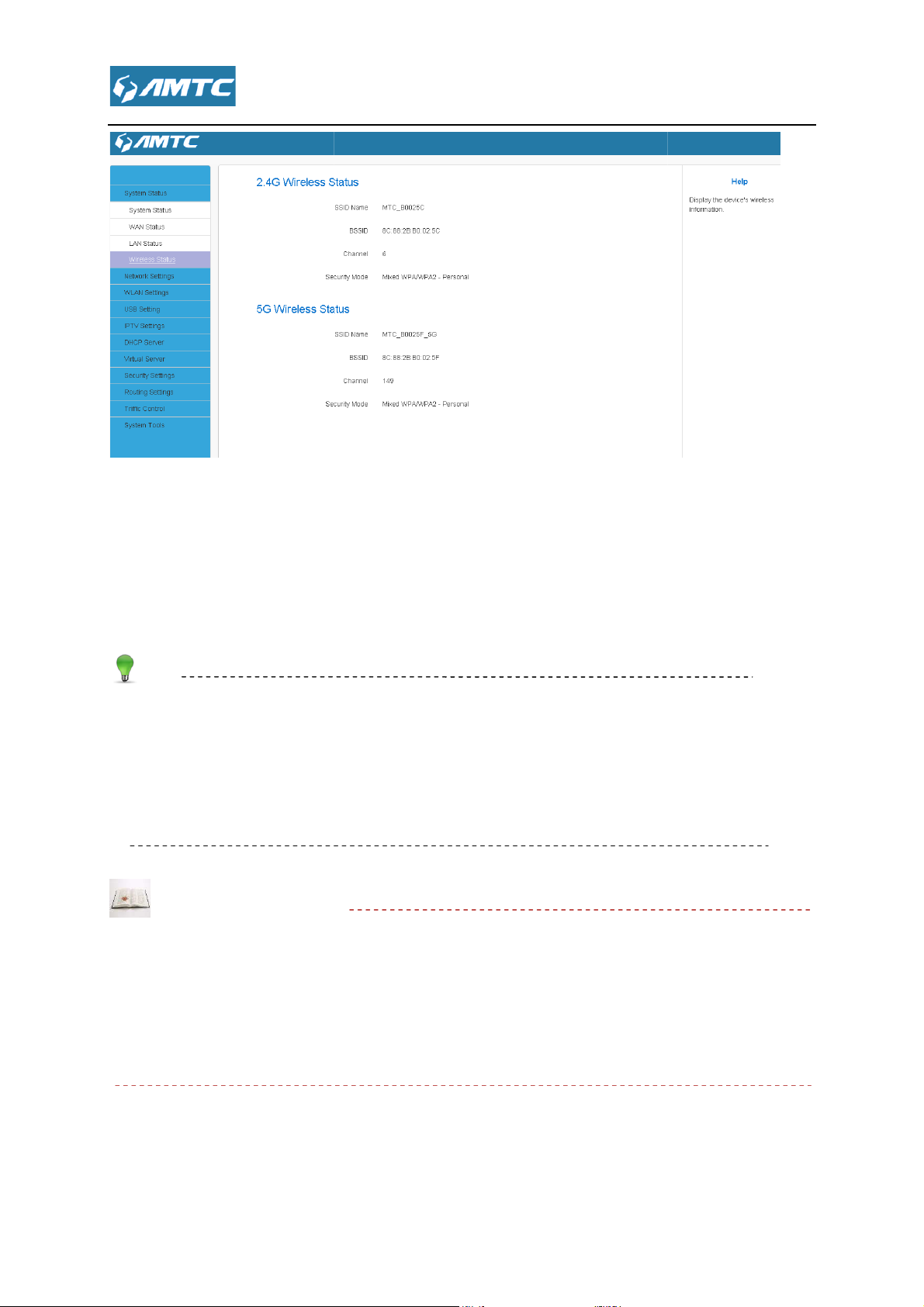
The name ofWireless
The MAC Address of Wireless.
The Channel of Wireless.
Encryption schemes.
The default SSID of 2.4G is
XXXXXX is the last six characters in the device's MAC address. You can find it on the label
attached on the bottom of the device
AutoSelect.
AutoSelect
least channel to improve the efficiency of the signal,
f you choice other mode, the channel will not change all the time not matte
_XXXXXX
the wireless signal will choice the user number is the
it works for most cases
Parameters Specification:
SSID Name:
:
::
BSSID:
Channel:
:
::
Security Mode:
Tips
Default channel is
Knowledge Expansion
AutoSelect: Under the “
.
MTC_XXXXXX, and SSID of 5G is MTC
.
”
_5G, where
I
good or bad.
.
r the channel is
Page 23
4.2
MAC Address Clone
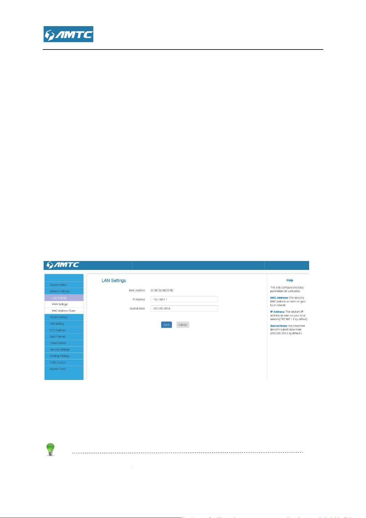
This page is to configure the basic
access the device’s settings through a web browser. Be sure to make a note of any changes you
.
Subnet M
and wait for the router reboot automatically.
It displays the Router’s LAN MAC address.
It displays the Router’s LAN IP address.
it displays the Router
Default IP address and subnet mask are respectively 192.168.
in this page you can set
parameters for LAN ports. This IP address is to be used to
.1 and 255.255.255.0.
Network Settings
T Click “Network Settings
Settings”, “WAN Settings”, “
4.2.1 LAN Setting
apply to this page
Set Steps::::
①
①
Click “Network Settings”
①①
②
②
Select“LAN Settings”.
②②
③
③
Enter IP Address,
③③
④
④
Click “Save”
④④
,
,,
” enter the Network setup web page,
”.
ask.
“LAN
Parameters Specification:
MAC Address:
IP Address:
Subnet Mask:
Tips
1.
:
::
:
::
’s LAN subnet mask.
1
Page 24
sure to make a note of any changes you apply to this page. If you change the LAN IP
address of the router, you have to open a new connection to the new IP
again. Also, you have to set the default gateway addresses of all LAN PCs to this new IP
3. The router's LAN IP address and WAN IP address cannot be on the same IP segment. If not,
the router will not be able to access Internet.
“Network Settings”
It displays the routers mode
Configuration the Internet access
Dynamic IP(DHCP)
address and log in
If your ISP provides you with an Ethernet cable from the
incoming Internet side IP information (IP address, subnet
mask, gateway IP address, DNS server address), your ISP
2. Be
address.
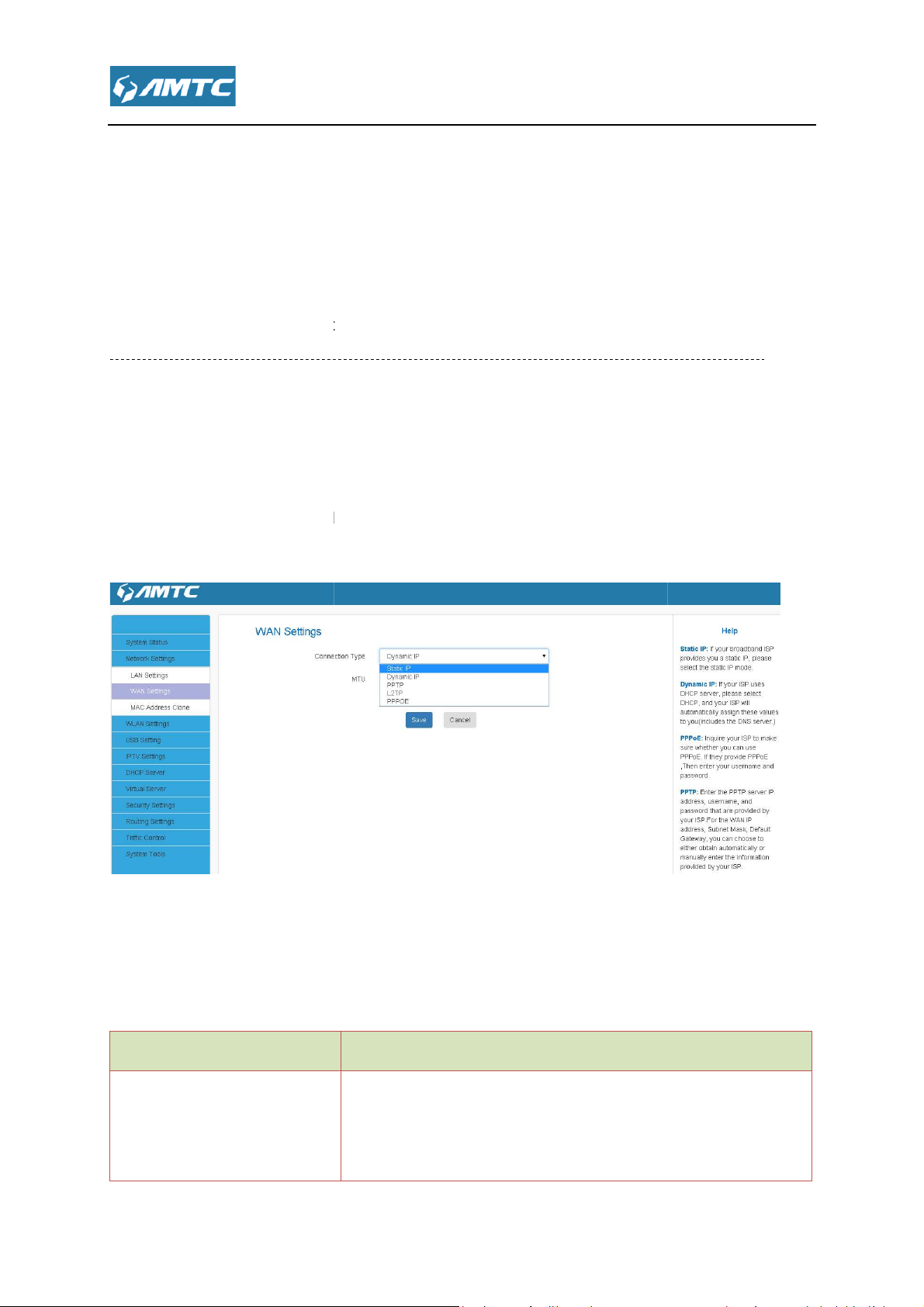
4.2.2 WAN Setting
Plug Internet cable to WR1201
Set Steps::::
①
①
Enter the web and Select
①①
②
②
Click the“WAN Settings”.
②②
WAN port.
.
Parameters Specification:
Connection Type:
1、
Support Static IP mode、
WAN Connection Type
Static IP mode
.
、PPOE.
Instruction
Page 25

“Static IP”
Enter IP, Subnet Mask, Gateway, MTU, DNS
Select Static IP.
IP Address/Subnet Mask/WAN subnet mask/Gateway/Primary DNS Server/Secondary
Enter the ISP information you gathered inGettingPrepared.
to save your settings.
cable from the incoming
Internet side but no ISP login account or IP information, your ISP
If your ISP provides you with an Ethernet cable from the
incoming Internet side and ISP login account, your ISP uses a
Dynamic IP
PPOE
1.1> Static IP mode
Set Steps::::
①
①
Click“Network Settings”.
①①
②
②
Select “WAN Settings”.
②②
③
③
Select Connection Type
③③
uses a static IP connection.
If your ISP provides you with an Ethernet
uses a DHCP connection.
PPOE connection.
.
④
④
④④
⑤
⑤
Click“Save” to confirm.
⑤⑤
Parameters Specification:
Connection Type:
DNS Server:
Click Save
Tips
Page 26

MTU better to choose the default values.
.
“Dynamic IP”
MTU better to choose the default values.
.
“PPOE”
UserName
WAN Status
1.2>Dynamic IP mode.
Set Steps::::
①
①
Click “Network Settings”
①①
②
②
Select“WAN Settings”.
②②
③
③
Select Connection Type
③③
④
④
Click“Save” to confirm.
④④
.
Tips
1.3>PPOE
Set Steps::::
①
①
Click “Network Settings”
①①
②
②
Select “WAN Settings”.
②②
③
③
Select Connection Type
③③
④
④
Enter the ISP login
④④
⑤
⑤
Click“Save” to confirm.
⑤⑤
⑥
⑥
Click “System Status”--->“
⑥⑥
.
,the ISP login Password.
” to confirm
Page 27

Maximum Transmission Unit. It is the size of the largest data packet
over the network. The default value is
The common MTU sizes and applications are listed in the table below.
Typical for connections that do not use PPOE or VPN.
Used in PPOE environments.
size to use for pinging. (Larger packets are fragmented.)
Used in some DHCP environments.
Used in PPTP environments or with VPN.
A wrong/improper MTU value may cause Internet communication problems. For example, you
access certain websites, frames within websites, secure login pages, or
modify it unless necessary, but if a specific website or web application software cannot
open or be enabled, you can try to change the MTU value to 1500, 140
MAC Address Clone
Knowledge Expansion
MTU:
MTU Application
1500
1492
1472 Maximum
1468
1436
Note
that can be sent
1500.
may be unable to
FTP or POP servers.
Do not
0.
4.2.3
Page 28

Some ISPs (Internet Service Providers) require end
network. This feature copies your current PC's MAC address to the router.
MAC Address Clone
ou can set this page from three methods
To Restore to Factory Default MAC
Restore to factory Default MAC
to save your settings.
To clone the MAC address of the computer that you are now using to the router:
to save your settings.
To manually enter the MAC address allowed by your ISP:
Enter the MAC address allowed by your ISP.
to save your settings.
computer or broadband modem authorized by your ISP
Default MAC:
Clicking this button copies the MAC address of the computer that you are now
user's MAC address to access their
Reset the router’s WAN MAC to factory default.
Set Steps::::
①
①
Click “Network Settings”.
①①
②
②
Click “
②②
③
③
Y
③③
-
”.
:
1、、、、
1> Click “
2> Click Save
2、、、、
1> Click Clone My PC’s MAC
2> Click Save
3、
、
、、
1>
2> Click Save
”
Address.
Parameters Specification:
MAC Address:The
Knowledge Expansion
1. Restore toFactory
2. Clone MAC:
.
Page 29

o the router. Also, you can manually enter the MAC address that you want to use. You
have to use the computer whose MAC address is allowed by your ISP
” enter the configure page , here you can configure “
Advanced Settings
w
-----------------------------------------------------------------------------
router working frequency. They use different protocol
2.4G band and household appliances are
Here you can configure the basic wireless settings of the router
(Default name is
Channel BandWidth
Access Control
You coule change it by
using the same frequency
using t
4.3 WLAN Settings
Click “WLAN Settings
“Security Settings”,”
Status”.
The Wireless includes two
clicking button
Knowledge Center
2.4GHz and 5GHz is the
802.11g and 5G use 802.11a.
band. 5G band use few. So 5G
4.3.1 Basic Settings
”, “WPS Settings”, “
orking frequency band: 2.4GHz and 5GHz.
or
has strong anti-jamming capability.
Base Settings”,
”, “Connection
-----------------: 2.4G use
Set Steps::::
①
①
Click“WLAN Settings”.
①①
②
②
Select “Basic Settings”.
②②
③
③
Wireless Enable.
③③
④
④
Select Network Mode
④④
⑤
⑤
Enter SSID name
⑤⑤
⑥
⑥
Select“Channel”.
⑥⑥
⑦
⑦
Select “
⑦⑦
i3005_XXXXXX).
”.
Page 30

Enable
It is the unique nameof the wireless network and can be modified.
Select “Enable” to enable the router’ SSID to be scann
devices. The default is enabled. If you disable it, the wireless devices must know the SSID for
This is the MAC address of the device's wireless int
The currently used channel by the router. Select an effective channel of the
The default is AutoSelect.
Select an appropriate channel bandwidth to enhance the wireless
performance. Select 20/40M when th
The SSID must be entered.
1. The default SSID of 2.4G is
XXXXXX is the last six characters in the device's MAC address. You can find it on the label
to promote its throughput
_XXXXXX
Parameters Specification:
Wireless: wireless “
SSID:
Broadcast (SSID):
communication.
BSSID:
Channel:
wireless network.
Channel Bandwidth:
Note
The wireless Enable.
” or “Disable”.
e network has 11b/g/n
ed by wireless
erface.
Tips
MTC_XXXXXX, and SSID of 5G is MTC
_5G , where
Page 31

attached on the bottom of the device.
2.
If you are not an advanced user, it is advisable to only change the SSID (name of the network)
other items unchanged
Network Mode (802.11 Mode):
This network mode delivers wireless speed up to 11Mbps and is only compatible with
This network mode delivers wireless speed up to 54Mbps and is only compatible with
This network mode delivers wireless speed up to 54Mbps and is compatible
with 11b/g wireless clients.
This network mode de
with 11b/g/n wireless clients
With the wireless security function, you can prevent others from connecting to your wireless
network and using the network resources without your
illegal users from intercepting or intruding your wireless network
”
to use you settings and click
Select a correct mode according to your wireless clients.
livers wireless speed up to 300Mbps and is compatible
consent. Meanwhile, you can also block
and channel and leave
Knowledge Expansion
11b:
11b wireless clients.
11g:
11g wireless clients.
11b/g mixed:
11b/g/n mixed:
.
4.3.2 Security Settings
Set Steps::::
①
①
Click “Network Settings”.
①①
②
②
Select “Security Settings
②②
③
③
Select“Security Mode”.
③③
④
④
Click “Apply”
④④
.
“Save” to save your settings.
Page 32

Personal
Personal
You can enable personal or mix mode, but you must make sure that
supports the selected encryption method.
Mixed WPA/WPA2
cipher types
Personal
wireless clients can join your wireless network
Security mode:WPA –
Security mode
Disable
WPA – Personal
WPA2 – Personal
Mixed WPA/WPA2 –
Note
WPA/WPA2-Personal:
the wireless client also
、WPA2 – Personal、
Instruction
Not open this function
Support AES and TKIP cipher types
Support AES, TKIP and TKIP+AES
Both WPA-Personal and WPA2-
– Personal.
secured
.
Page 33

Fi Protected Access Algorithms.
The default is 12345678.
Wired Equivalent Privacy
encryption, to prevent illegal users wiretapping or invade the wireless network
(Advanced encryption standard) i
wireless speed can reach up to300Mbps.
(Temporal Key Integrity Protocol)
security issues, TKIP is in WEP password outermost layer of the existing “shell”If
up to 54Mbps.
If Selected, both AES and TKIP secured wireless clients can join your wireless
Enter a valid time period for the key to be changed
Recommended that you choice
efficiency and ensure the security of wireless network.
the wireless transmission of data between two devices for
s an iterative, symmetric key group password
Responsible for handling the wireless encryption part of
.
mode , make sure the wireless
eanwhile, avoid some kind of
Parameters Specification:
WPA Algorithms: Wi-
Pass Phrase:
Knowledge Expansion
1. WEP: (
2. AES:
3. TKIP:
wireless speed can reach
4. TKIP+AES:
network.
5. Key Renewal Interval:
)is
.
.If selected,
selected,
Tips
“WPA-Personal” + ”AES”
M
Page 34

wireless network card does not support
network.
Backup Configuration Procedures:
Configure security mode, cipher type and security key.
to save your settings.
-----------------------------------------------------------------
WEP is intended to provide data confidentiality comparable t
Wireless speed can reach up to 54Mbps if WEP
Wireless speed can reach up to 54Mbps if WEP
: Compatible with both Open and Shared. Clients can connect to
network either using Open or Shared
Select a key to be effective for the current WEP encryption. For example, if you
select Key 2, wireless clients must join your wireless network using this Key 2.
WPA personal, support
WPA2 personal, support AES, TKIP and TKIP+AES cipher types.
PSK:
clients can join your wireless network
If selected, wireless speed can reach
If selected, wireless speed can reach up to 54Mbps.
If selected, both AES and TKIP secured wireless clients can join your wireless
Enter a valid time period for the key to be changed.
ou can configure the advanced wireless setting for the Router; including Beacon Interval, TX
, cause cannot connect the wireless
-------------------
o that of a traditional wired
Open is selected.
Shared is selected.
PSK secured wireless
①
①
①①
②
② Click Save
②②
security mode
Knowledge Center
1. WEP:
network.
2. Open:
3. Shared:
4. Mixed WEP
5. Default Key:
6. WPA-PSK:
7. WPA2-PSK:
8. Mixed WPA/WPA2-
-
-
AES and TKIP cipher types.
If selected, both WPA-PSK and WPA2-
.
your wireless
9. AES:
10. TKIP:
11. TKIP+AES:
network.
12. Key Renewal Interval:
up to300Mbps.
4.3.3 Advanced Settings
Y
Page 35

Power and Basic Data Rate and so on.
provides you with two main functions:
if your wireless network unencrypted
f your wireless network encrypted, WPS can make you quickly connect your encrypted
WPS can quickly encryption your wireless network.
4.3.4 WPS Settings
Set Steps::::
①
①
Click “WLAN Settings”.
①①
②
②
Select “WPS Settings”.
②②
Knowledge Expansion
WPS
I
wireless network.
,
Page 36

methods:
Using routers and physical or logical button on a wireless device to connect WPS.
ou have below methods to connect WPS:
Using the router WPS button on the rear panel for the PBC connection
Hold the router on the rear panel of the WPS button
The router's WPS led flashes two minutes
the WPS/PBC connect to your wireless signal
Knowledge Expansion
The router wireless SSID, safe mode resumed to not configured mode.
Encryption and password
factory default, safe mode is unencrypted.
ss control is actually based on the MAC address to permit or forbid
clients to access the wireless network
let go
In the wireless client devices use
M
, the router
Parameters Specification:
The WPS provides below
PBC:
Y
1、、、、
①
①
Click “Enable”
①①
②
②
Click “Save”
②②
③
③
③③
④
④
④④
resetOOB:
for 3 seconds, then
, During this time,
ake the WPS reset
the SSID,
, after the completion of the reset
4.3.5 Access Control
Wireless acce
’s SSID is
specified
Page 37

The Wireless Access Control is based on the MAC address of the wireless adapter
to determine whether it communicates with the Router or not;
allow all wireless clients to join your wireless network.
allow ONLY
disallow ONLY
Wireless Access Control Application Example:
To only allow your own notebook at the MAC address of
Enter the MAC address of the wireless device you want to restrict. Here in this example, enter
to add the MAC address to the MAC address list.
to save your se
reless clients to join your wireless network.
the specified wireless clients to join your wireless network.
Set Steps::::
①
①
Click “WLAN Settings”.
①①
②
②
Select “Access Control”
②②
.
Parameters Specification:
1. Select“Off” to
2. Select “Allow”
3. Select “Block”
network
Set Steps::::
①
①
Select Allow.
①①
the specified wi
00:12:35:EC:DF:25
to join your wireless
②
②
②②
00:12:35:EC:DF:25.
③
③
Click Add
③③
④
④
Click Save
④④
ttings.
Page 38

Tips
Up to 10 wireless MAC addresses can be configured
If you don't want to configure the complex wireless security settings and want to disallow
others to join your wireless network, you can configure a wireless access control rule to allow
your own wireless device
This page shows the current wireless access list
The bandwidth here refers to the channel bandwidth instead of wireless connection rate.
You can know whether there are
You could configure the USB drive connected to the Router.
unauthorized accesses to your wireless network by viewing
only
4.3.6 Connection Status
Click “Refresh” to update.
Tips
the wireless client list.
4.4 USB Setting
4.4.1 Device Sharing
Page 39

” button , wait a minute , you could see the
Delete
You can configure media server on this page. You could enable this server to share the media
information in USB driver. And other user in this local area network could see these information
connected to the Router.
” to enable or disable sharing the volume.
Click “Scan
You can click the “Share” or “
4.4.2 Media Server
USB drive
your shared.
Page 40

You could connect a network pri
this local area network could use the printer.
You could add user in your USB Server. And other user could use this user name and password to
Print Server.
4.4.3 Print Server
4.4.4 User Accounts
nter to the router and Enable the
The other user in
login in the USB Server
Page 41

function, you could connect a set
enter the Virtual Server configure page ,here you can set
top box to the router to use.
4.5 IPTV Settings
If you enable this
4.6 DHCP Server
-
Click “DHCP Server”
“DHCP List & Binding”.
4.6.1 DHCP Server
Set Steps::::
“DHCP Server”,
Page 42

Select whether enable or disable the DHCP server feature
Start IP Address and End IP Address:
the IP address pool here. These addresses should be part of the same IP address subnet as
the router’s LAN IP address.
Knowledge Expansion
(Dynamic Host Configuration Protocol)
When you enable the DHCP Server, the DHCP Server will automatically allocate an unused
IP address from the IP address pool specified in this screen to the requesting device as long
vice is set to “Obtain an IP Address Automatically”.
If you disable this feature, you have to manually configure the TCP/IP settings for all PCs on
your LAN to access Internet.
is the length of the IP address lease before it is refreshed.
You can specify the starting and ending address of
assigns an IP address to each device on the
①
①
Click “DHCP Server”.
①①
②
②
Select “DHCP Server”.
②②
Parameters Specification:
DHCP Server:
Enter the Lease Time
DHCP
LAN/private network.
as the de
.
Lease Time:
Tips
Page 43

By default, the router functions as a DHCP server. Do not disable the DHCP server feature
unless you want to manually configure the TCP/IP settings for all PCs on your LAN.
Lease time will be renewed automatically upon expiry. No additional configurat
If you are not an advanced user, the default DHCP server settings are recommended.
In order to use the function of the router's DHCP server, LAN in the computer's TCP/IP protocol
must be set to “automatically obtain IP”
& Binding
& Binding
nter the IP Address and MAC Address
add to the DHCP list
” to update the related DHCP client information
whether there are unauthorized accesses by viewing the client list
Also, you can specify a reserved IP address for a PC in the LAN. That PC will always receive
the same IP address each time when it accesses the DHCP server. Reserved IP addresses
assigned to servers that require permanent IP settings.
1.
needed.
2.
4.6.2 DHCP List
Set Steps::::
①
①
Click “DHCP Server”.
①①
②
②
Select “DHCP List
②②
ions are
.
”.
Parameters Specification:
E
Click “Add”
Click “Refresh
Tips
You can know
could be
.
.
Page 44

Static Assignment Application Example:
To have a PC at the MAC address of 44:37:E6:4F:37:3B always receive the same IP address of
Enter the last number of the IP address you want to reserve, for example,
Enter the MAC address of
to save your settings.
1. If the IP address you have reserved for your PC is currently used by anothe
not be able to obtain a new IP address from the device's DHCP server, instead, you must
manually specify a different IP address for your PC to access Internet.
2. For PCs that has already obtained IP addresses, you may need to perfo
activate the configured static IP addresses
enter the Virtual Server configure page ,here you can set
uPnP Settings
rm the Repair action to
192.168.1.200
Parameters Specification:
Click “Add”.
Click “Save”
Tips
4.7 Virtual Server
200.
50:7B:9D:12:41:69
r client, then you will
Click “Virtual Server”
“DMZ Settings”, “
”.
“Port Range”,
Page 45

resources on your PC with your friends who are not in your LAN. But, by default,
the router's firewall blocks inbound traffic from the Internet to your computers except replies to
your outbound traffic. You can use the Port Forwarding feature to create exc
that your friends can access these files from external networks.
When accessing your PC from Internet, type "protocol://xxx.xxx.xxx.xxx:port number" into your
browser’s address or location field. The protocol and port are the ones u
"xxx.xxx.xxx.xxx" is the WAN IP address of your router. For example, a FTP server uses the ftp
protocol and 21 (standard port number).
As shown in the figure above, your PC at
server on port number 21. Your friends want to access this FTP server on your PC from external
To successfully implement the port forwarding
1. Make sure your WAN IP address (Internet IP address) is a public IP address. Private IP
addresses are not routed on the Internet.
2. Make sure you enter correct service port numbers.
3. To ensure that your server computer always has
in firewall and some anti
accessing resources on your PC. So it is advisable to disable them before using this feature
eptions to this rule so
sed by the service and
connects to the router and runs a FTP
the same IP address, assign a static IP
virus programs may block other PCs from
4.7.1 Port Range
You want to share
Set Steps::::
①
①
Click “Virtual Server”.
①①
②
②
Select “Port Range”.
②②
Application Example:
network.
Tips
address to your PC.
4. Operating System built-
192.168.2.10
feature, note below:
.
Page 46

Enter the start/end port number which ranges the External ports used to set
the server or Internet applications.
Enter the IP address of the PC where you want to set the
example, enter 192.168.1.100.
Specify the protocol required for the service utilizing the port(s)
(TCP/UDP/Both) for the application.
to apply this function,
to save your settings.
192.168.1.100
your friends only need to enter
Add DMZ Host IP which is the LAN IP
applications.
when accessing your FTP server from external network,
Parameters Specification:
Start/End Port:
IP Address:
Protocol:
“Enable”
Click ‘Save’
If your WAN IP address is
4.7.2 DMZ Settings
Set Steps::::
①
①
Click “Virtual Server”.
①①
Here in this example, enter 21.
Here in this
. Select the protocol
“Delete” cancel this host configure.
ftp://192.168.1.100:21 in their browsers.
②
②
Select “DMZ Settings”.
②②
③
③
Select “Enable”
③③
④
④
④④
⑤
⑤
Click“Save” to confirm.
⑤⑤
Page 47

The DMZ Settings screen allows one local computer to be exposed to the Internet for use of a
purpose service such as Internet
DMZ hosting forwards all the ports at the same time to one PC.
DMZ host poses a security risk. A computer configured as the DMZ host loses much of the
protection of the firewall and becomes vulnerable to attacks
2. Hackers may use the DMZ host computer to attack other computers on your network
The Universal Plug and Play (UPnP) feature allows network devices, such as computers from
Internet, to access resources on lo
discovered automatically by the UPnP service application on the LAN. If you use applications such
to
, or remote assistance (a feature in Windows XP), you may need to enable Universal
Plug and Play (UPnP) for better experience.
uPnP Settings
from external networks.
enabled devices can be
time communications such as instant
. The UPnP feature is enabled by
Tips
special-
Note
1.
4.7.3 uPnP Settings
gaming or videoconferencing.
cal host or devices as needed. UPnP-
as multiplayer gaming, peer-
-peer connections, real-
messaging
Click Virtual Server ->
to enter the UPnP page
default.
Page 48

enter the Security configure page ,here you can set
”
This section allows you to set the times specific clients can or cannot access the Internet via the
devices’ assigned IP addresses and service port. Click
>Client Filter
4.8 Security Settings
Click “Security Settings”
Filter”, “MAC Filler”, “Prevent
4.4.1 Client Filter
the configuration page.
, “Remote WEB”, “WAN Ping”.
Security Settings -
“Client Filler”,“URL
to enter
Page 49

Page 50

4.4.2 URL Filter
This section is to set URL filtering access. If you want to enable this function, please activate
the checkbox. Select one policy from the drop-down menu and enter a policy name in the field. Of
course, you can set the access restriction in details (e.g. the fixed IP range, URL, times and days).
Note: When time is 0:0~0:0, it express 24 hours.
Set Steps::::
①
①
Click“Security Settings”.
①①
②
②
Select “URL Filter”.
②②
URL Filter Application Example:
To prevent your home PC (192.168.1.100) from accessing “YouTube” from 8:00 to 18:00 during
working days: Monday- Friday.
Set Steps::::
①
①
Enter a Policy Name
①①
②
②
Enter the Start IP and End IP here for example:192.168.1.100
②②
③
③
Enter part of or the entire domain name of the web site you wish to restrict. Separate different
③③
domain names or domain name key words with a comma, for example, "YouTube,
Hollywood.com"
④
④
Select time and day
④④
⑤
⑤
Click “Save” to save your settings.
⑤⑤
Page 51

Tips
. Different URL strings must be separated with a comma. To match all websites, use * (asterisk)
to 10 filter rules can be configured.
. If you have not set up the system time for this device, click
set up correct time and date for the rules to be effective
Tools
1
2.Up
3
4.4.3 MAC Filter
System
-> Time Settings to
Page 52

4.4.4 Prevent
This section is to protect the internal network from exotic attack such as SYN Flooding attack,
Smurf attack, LAND attack, etc
4.4.5 Remote WEB
This section is to allow the network administrator to manage the router remotely. If you want to
access the router remotely, please select “Enable”.
Set Steps::::
①
①
Click“Security Settings”.
①①
②
②
Select “Remote WEB”.
②②
③
③
Enter the Port
③③
④
④
Click “Save” to confirm.
④④
Page 53

Parameters Specification:
The management port to be open to outside access.
1. For better security, configure a port
interface, do not use the number of any common service port (1
2. Make sure your WAN IP address (Internet IP address) is a public IP address. Private IP
addresses are not routed on the Internet.
It is unsafe to make your router remotely accessible to all PCs on external network. For better
security, we suggest that only enter the IP address of the PC for remote management
Remote Web Management Application Example:
To access your router (WAN IP
at your office via the port number
to save your settings.
Type “
field and you can access the router at your home remotely.
65535) as remote web management
) at your home from the PC (
into your browser’s address or location
Port:
Tips
3.
number (between1025-
address: 172.16.87.160
6060.
-1024).
210.16.87.154)
Set Steps::::
①
①
Management “Enable”.
①①
②
②
Enter the Port: 6060.
②②
③
③
Click “Save”
③③
In the PC 210.16.87.154
http:// 172.16.87.160:6060”
Page 54

Knowledge Expansion
1. Port: This is the management port to be open to outside access. The default setting is 8080.
This can be changed
4.4.6 WAN Ping
The ping test is to check the status of your internet connection. When disabling the test, the
system would prevent the ping test from WAN.
Set Steps:
①①①①
Select the “Expert Setting”
Page 55

②②②②
Select the “WAN Ping”
③③③③
Select the “Enable”
4.9 Routing Settings
In this page you can view the routing table information.
Click “Refresh” to update
Destination IP: The IP address of the final destination. “0.0.0.0” indicates any network
segment.
Subnet Mask: The subnet mask for the specified destination.
Gateway: This isthe next router on the same LAN segment as the router to reach.
Interface: The interface between your router and the final destination.
4.10 Triffic Control
Traffic control is used to limit communication speed in the LAN.Up to 20 entries can be
supported with the capability for at most 254 PCs' speed control,including for IP address range
configuration.
Page 56

Tips
2. The volume of uplink traffic/downlink traffic should not be larger than that allowed on your
router's WAN (Internet) port. You
3. The bandwidth for ADSL/DSL line usually refers to the download bandwidth
Bandwidth Control Application Example:
broadband service with your neighbor (at 192.168.
large volume of data from Internet, which sharply frustrates your Internet surfing experience; you
can use this feature to set limits for the volume of Internet traffic he can get. For example, you can
split the 4M into two, so your neighbor
: Check the
can ask your ISP to provide the volume of Internet traffic.
). He alwa
can only use up to 2M Internet traffic and you can enjoy 2M.
Control feature.
1. 1M=128KByte/s.
You share a 4M-
1.102
ys downloads a
Set Steps::::
①
①
EnableTraffic Control
①①
Enable box to enable the Traffic
Page 57

②
Enter the last number of the IP address. Here in this example, enter
Set a limit to regulate upload bandwidth of PCs on the LAN. Here in this example, enter
, and 256 in second box.
Set a limit to regulate download bandwidth of PCs on the LAN.
Check to enable the current rule.
o add current rule to the rule list.
to save your settings.
enter the configure page ,here you can set
Restore to Factory
> Time
Configured time and date info will be lost if the device gets disconnected from power supply.
However, it will be updated automatically when
based features (e.g. firewall), the time and date info shall be set correctly first, either
the device reconnects to Internet. To activate
②
IP Range:
②②
boxes.
③
③
Up:
③③
101 in both
32 in first boxes
④
④
Down:
④④
⑤
⑤
Apply:
⑤⑤
⑥
⑥
Add: Click t
⑥⑥
⑦
⑦
Click Save
⑦⑦
4.11 System Tools
Click “SystemTools”
“DDNS”,“Backup/Restore”, “
Password”, “System Log”.
4.11.1 Time Settings
“TimeSettings”,
”, “firmware Upgrade”,
“Reboot”, “Change
Click System Tools -
Tips
timemanually or automatically
Settings to enter the time page.
Page 58

Set Steps::::
①
①
Click “System Tools”.
①①
②
②
Select “Time Settings”.
②②
③
③
The time will synchronize with the internet automatically in the default situation
③③
④
④
Select Time Zone
④④
⑤
⑤
If you can enter the time and date manually or click “Sync with your PC”, synchronize
⑤⑤
automatically.
⑥
⑥
Click Save to save you settings.
⑥⑥
Synchronize with your PC:Specify a time interval for periodic update of time and date
information from your host.
4.11.2 DDNS
Page 59

4.11.3 Backup & Restore
Set Steps::::
①
①
Click “System Tools”.
①①
②
②
Select “Restore to Factory”.
②②
Parameters Specification:
This “Restore” button is to reset all configurations to the default values. It means the Range
Page 60

Extender will lose all the settings you have set. So please note down the related settings if
necessary.
Default Password: admin
Subnet Mask:255.255.255.0
Default IP:192.168.1.1
Note
If you enable this option, all current settings will be deleted and be restored to factory default
values. You will have to reconfigure Internet connection settings and wireless settings.
Do not restore factory default settings unless the following happens:
1> You need to join a different network or unfortunately forget the login password.
2>You cannot access Internet and your ISP or our technical support asks you to reset the
router.
--------------------------------------------------------------------------------------------------------------------------
4.11.4 Firmware Update
The router provides the firmware upgrade by clicking the “Upgrade”after browsing for the
firmware upgrade packet. After the upgrade is completed, the router will reboot automatically.
Set Steps::::
①
①
Click “System Tools”
①①
Page 61

②
②
Select “FirmwareUpgrade”
②②
③
③
Click “Browse”, select the upgrade file
③③
④
④
Click “Upgrade”, and wait for it to complete.
④④
Note
1. Before you upgrade the firmware, make sure you are having a correct firmware. A wrong
firmware may damage the device.
2. It is advisable that you upgrade the device's firmware over a wired connection. DO NOT
interrupt the power to the router when the upgrade is in process otherwise the router may be
permanently damaged.
4.11.5 Restore to Factory
Set Steps::::
①
① Click “System Tools”.
①①
②
② Select “Restore to Factory”.
②②
Parameters Specification:
This “Restore” button is to reset all configurations to the default values. It means the Range
Page 62

Extender will lose all the settings you have set. So please note down the related settings if
necessary.
Default Password: admin
Subnet Mask:255.255.255.0
Default IP:192.168.1.1
Note
If you enable this option, all current settings will be deleted and be restored to factory default
values. You will have to reconfigure Internet connection settings and wireless settings.
Do not restore factory default settings unless the following happens:
1>You need to join a different network or unfortunately forget the login password.
2>You cannot access Internet and your ISP or our technical support asks you to reset the
router.
4.11.6 Reboot
When a certain feature does not take effect or the device fails to function correctly, try
rebooting the device.
Rebooting the Wifi Router is to make the settings configured go into effect or to set the Range
Extender again if setting failure happens.
Page 63

4.11.7 Change Password
You can change the password by this function
Change Password
New Password
to save you settings.
The default login password is admin.
The valid password must be between 3~12 characters and only include letters, numbers and
section is to view the system log. Click the “
the screen.
Set Steps::::
①
①
Click “System Tools”
①①
②
②
Select “
②②
③
③
Enter “Old Password”“
③③
④
④
Click “Save”
④④
Tips
underscore
4.11.8 System Logs
”
”and“Confirm New Password”
The
Click the “Clear” to clear
Refresh” to update the log.
Page 64

Set Steps::::
①
①
Click “System Tools”
①①
②
②
Select “System Log”
②②
③
③
Click “Refresh” can update the information
③③
④
④
Click “Clear” to clear the screen
④④
Page 65

Appendix
1 Configure PC TCP/IP Settings
Windows 7
①
① Click Start -> Control Panel.
①①
Page 66

②
.
Sharing Center
② Click Network and Internet
②②
③
③ Click Network and
③③
.
Page 67

④
Change adapter settings
Local Area Connection
④ Click
④④
.
⑤
⑤ Click
⑤⑤
and select Properties.
Page 68

⑥
⑥ Select Internet Protocol Version 4 (TCP/IPv4) and click Properties.
⑥⑥
Page 69

⑦
⑦ Select Obtain an IP address automatically and click OK.
⑦⑦
Page 70

⑧
⑧ Click OK on the Local Area Connection Properties window to save your settings.
⑧⑧
Page 71

Windows XP
①
① Right-click My Network Places and select Properties.
①①
②
② Right click Local Area Connection and select Properties.
②②
Page 72

③
③ Select Internet Protocol Version 4 (TCP/IPv4) and click Properties.
③③
④
④ Select Obtain an IP address automatically and click OK.
④④
Page 73

Page 74

⑤
⑤ Click OK on the Local Area Connection Properties window to save your settings.
⑤⑤
Page 75

2 FAQs
This section provides solutions to problems that may occur during installation and
operation of the device. Read the following if you are running into problems.
1. Q: I cannot access the device's management interface. What should I do?
Make sure the System LED on the device's front panel is on.
Make sure all cables are correctly connected and the corresponding LAN LED on
the device is on.
Verify that your PC's TCP/IP settings are configured correctly. If you select the
"Use the following IP address" option, set your PC's IP address to any IP address
between 192.168.1.2~192.168.1.254. Or you can select the "Obtain an IP address
automatically" option.
Delete your browser cache and cookies or use a new browser. Make sure you
enter 192.168.1.1 in the address bar.
Press the WPS/RST button for about 10 seconds to restore your device to
factory default settings. Then log to your device again.
2. Q: I changed the login password and unfortunately forget it. What should I do?
Press the WPS/RST button for over 10 seconds to restore your device to factory default
settings.
3. Q: My computer shows an IP address conflict error after having connected to the
device. What should I do?
Make sure there are no other DHCP servers on your LAN or other DHCP servers
are disabled.
Make sure the device's LAN IP is not used by other devices on your LAN. The
device's default LAN IP address is 192.168.1.1.
Make sure the statically assigned IP addresses to the PCs on LAN are not used
by others PCs.
4. Q: I have problems connecting to Internet/Secure websites do not open or
Page 76

displays only part of a web page. What should I do?
This problem mainly happens to users who use the PPPOE or Dynamic IP Internet
connection type. You need to change the MTU size. Try changing the MTU to 1450 or 1400.
If this does not help, gradually reduce the MTU from the maximum value until the problem
disappears.
3 Factory Default Settings
The table below lists the factory default settings of your device.
Item Default Settings
Login IP Address 192.168.1.1
Router Login
Network
Settings
LAN Settings
(LAN)
Login User Name admin
Login Password admin
Internet Connection Type Mode Auto-switch Enabled
1492 (PPPOE)
MTU
1500 (DHCP/ Static IP)
WAN Speed Auto
DNS Disable
IP Address 192.168.1.1
Subnet Mask 255.255.255.0
DHCP Server Enabled
IP Pool 192.168.1.100~192.168.1.200
(GMT+08:00)Beijing, Chongqing, Hong
Time Zone
Kong, Urumqi
Wireless Enabled
MTC_XXXXXX (where XXXXXX is the
2.4G Wireless
SSID
802.11 Mode 11b/g/n mixed Mode
last six characters in the device's MAC
address)
Page 77

SSID Broadcast Enabled
Channel 2437MHz(Channel 6)
Channel Bandwidth 20/40
Extension Channel 2417MHz(Channel 2)
Wireless Security Disabled
Wireless Access Control Disabled
Country America
Wireless Enabled
MTC_XXXXXX (where XXXXXX is the last
5.0G Wireless
SSID
six characters in the device's MAC
address)
802.11 Mode 11a/an/ac mode
SSID Broadcast Enabled
Channel 5745MHz(Channel 149)
Channel Bandwidth 40
WMM Capable Enable
APSD Capable Disabled
Wireless Security Disabled
Wireless Access Control Disabled
Remote Web
Disabled
Management
Bandwidth Control Disabled
Others
DMZ Host Disabled
UPnP Enable
Internet Access
Disabled
Management
 Loading...