


KVM-7050W, KVM-9050W, KVM-7050W-2, KVM-9050W-2 LCD Monitors
USER MANUAL
Shenzhen Konvision Technology Co., Ltd
http://www.konvision.com

Shenzhen Konvision Technology Co,.Ltd www.konvision.com
2
Content
Notes ............................................................................................................ 3
Security ........................................................................................................
4
Screen Maintenance ................................................................................................ 4
Cabinet Maintenance ............................................................................................... 4
Installation ............................................................................................................... 5
Rack mount installation ……………………………...……………..…………………….5
Transportation ......................................................................................................... 5
Features ....................................................................................................... 6
Parts and Their functions ............................................................................. 9
Front view ................................................................................................................ 9
Rear view .............................................................................................................. 14
OSD Menu .................................................................................................. 16
Menu Structure ...................................................................................................... 16
Menu Operation ..................................................................................................... 18
Menu Item Description ............................................................................................18
Picture ........................................................................................................... 19
Img.Adj ...........................................................................................................19
Setup ............................................................................................................. 20
Audio ............................................................................................................. 22
PIP/PBP ........................................................................................................ 23
Scope………………………………………………………………………………..26
Status ............................................................................................................ 28
Pixel Measure.........................................................................................................28
Factory Reset .............................................................................................. 29
Remote Control ...........................................................................................
30

Shenzhen Konvision Technology Co,.Ltd www.konvision.com
3
● Notes
For the safety use of products, please read carefully the following
instructions regarding the installation, use and maintenance.
.
Please read carefully the product safety and operating instructions before the product is
operated.
. Please keep the safety and operating instructions for future reference.
. Please pay strict attention to the warnings and implement the products according to the
operating instructions closely.
. All operating instructions should be strictly enforced.
1. Please use the power cord recommended by manufacturer.
2. Please do not place heavy objects on the power cord.
3. Please do not expose this product to rain, humid, dusty places.
4. Please do not place vessels with liquid (such as cups, beverage bottles) on the
monitor.
5. Please do not place this product in high heat places.
6. Please make sure the earth terminal is good in order to avoid electric shock.
7. Please do not open the back cover to avoid electric shock. Please contact
professionals for service need.
8. If there is no image or sound, please unplug the power cord from the AC outlet
immediately. Please consult professionals if there still have problems after examining
carefully.
9. Do not place this product at unstable places such as cars, shelves or tables, as it is
easy to make the product falling down, may cause severely hurt to children and adults
and also damage to the product.
10. Please do not touch the power plug with wet hands, as it will cause electric shock.
11. Please do not expose the LCD panel in direct sunlight for a long time, it will result in
damage or aging of the LCD panel.

Shenzhen Konvision Technology Co,.Ltd www.konvision.com
4
12. Please display this product at a suitable temperature and humidity place.
13. Please do not spray any liquid things and/or add any objects into the monitor, it might
cause voltage instability and short-circuit, also can easily cause fires and blackouts.
14. If do not use the device for a long time, please unplug the power cord from the AC
outlet.
15. Please keep not less than 5cm space around the vents while using the monitor, in
order to obtain good heat dissipation effect.
●Security
Screen maintenance:
Please follow the below guidelines carefully to prevent discoloration, stains and scratches
on the screen:
- Avoid striking the screen with any object.
- Do not wipe the screen hard.
- Do not wipe the screen with solvents such as alcohol, thinner or gasoline.
- Do not spray detergent or other cleaners on the monitor or LCD panel, as it may cause
fault because of water droplets into the monitor.
- Do not write on the screen.
- Do not paste or stick any viscous markers on the screen.
Screen may be cleaned by gently wiping with lint free cloth to remove dust. For the more
difficult cleaning, use lint free cloth that has been very lightly dampened with detergent,
then dry any excess moisture from the monitor or LCD panel immediately to prevent
damage.
Cabinet maintenance:
Please follow the guidelines below to prevent potential damage.
- Do not wipe the cabinet with solvents such as alcohol,
thinner or gasoline.
- Do not use any pesticides and/or other volatile substances.
- Do not allow prolonged contact with rubber or plastic.
- Do not wipe the cabinet hard. Use a soft, lint free cloth to clean. If the cabinet cleaning is

Shenzhen Konvision Technology Co,.Ltd www.konvision.com
5
more difficult, use lint free cloth that has been very lightly dampened with detergent and
then dry it to wipe.
Installation:
- Keep adequate air circulation to prevent device internal overheating. Please do not
place the product on the surface of some certain objects (such as blankets, carpets,
etc.), as these objects may block the vents.
- Please keep the device away from heat generating sources, such as radiator, heaters
and air duct, also keep it away from much dust or mechanical vibration place.
Rack mount Installation:
- For rack mount installation, please keep 1U space from both top and bottom to make
sure adequate air circulation, or install an external electric fan. Please follow the
instructions and install with the rack mounts provided by manufacturer.
Transportation:
- This monitor is precise equipment and need professional packing materials to transport.
So do not to use packing materials provided by suppliers except KONVISION or its
authorized packing material suppliers.
When the following situations occur, please turn off the power, do not
insert the plug and contact a professional service staff to deal with
timely.
A. This product smells smoke and off-flavor.
B. When this product displays abnormal operating conditions, such as there is no picture
or sound.
C. When any liquid is splashed into the product or product dropped.
D. When the product soaked or fall into the water.
E. When the product has been damaged or other damage circumstances.
F. When the power cord or plug is damaged.

Shenzhen Konvision Technology Co,.Ltd www.konvision.com
6
The following does not belong to failures:
1. If the static image displayed too long, it will have residual image, which should be
attributed to the characteristics of LCD display but not a failure. Residual image will
disappear automatically after a period of time.
2. If this device used in a cold environment, the screen may appear residual image.
This is not a product failure, when the monitor temperature changes, screen will
return to normal conditions.
3. LCD screen may appear tiny spots (red, blue or green), this is not a fault, LCD
screens are manufactured with high precision technology, and a small number of
pixels may not be able to show intermittent.
4. Screen and cabinet will become warm gradually during operating.
● Features
High resolution LCD panel
- LED backlight and high resolution. High contrast, high-speed response and wide
viewing angle technology make the monitor can be used under variety of lighting
conditions.
Support full screen for Canon 5D II
- Full screen switch for Canon 5D II, and 1:1 mapping
Support user replaceable battery plates
- Support V-mount, Anton Bauer, and different brands 7.2V DV battery plates.
Durable and lightweight design
- Full metal and lightweight design provides cameraman easily and safely to field
shooting, and save space for OB vans/studio rooms equipment.
Two Colors Tally Indicator
- Two colors Tally indicator as red and green, to monitor each input signal and check
ON-AIR mode.
Auto-detection of all color system (PAL, NTSC, SECAM)
- This unit detects the color system automatically.

Shenzhen Konvision Technology Co,.Ltd www.konvision.com
7
3D video decoder
- Process 3D decoding on VIDEO signals, to realize better reduce cross color.
Motion-Adaptive Interlace to Progressive
- It converts interlaced video to progressive video by motion detection, reduce the
serrated image.
10BIT Signal Processing
- Signal input, signal processing and image output are 10bit data processing, to
ensure the details display of the image.
Y/C Input
- Decomposition for the luminance signal (Y) and chrominance signals (C) of the video
signal can be input through this connector.
SDI Input
- 3G/HD/SD-SDI video signal can be input through this connector.
YPbPr Input
- YPbPr video signal (Compatible YCbCr) can be input through this connector.
HDMI Input
- HDMI signal can be input through this connector.
Signal Source Loop through
- Signal that linked to the input connector will be enlarged and linked to output
connector. SDI reclock loop out ensure the signal without enervation.
Audio level meter (UV+PPM)
- Show the audio level meter (UV+PPM) for SDI embedded audio.
Waveform
- Display input signal waveform and color scope for SDI signal input monitoring. It
includes luminance waveform, YCbCr waveform and full screen luminance waveform.
Luminance waveform will mark with red if over the value specified by user.
Focus Assist
- Focus assist is to aid the cameraman focus on the main body by marking the
sharpest edge of the image with red.
False Color

Shenzhen Konvision Technology Co,.Ltd www.konvision.com
8
False color can Intuitively observe and calculate illumination level in the image,
luminance and illumination values display mapping as luminance level, from darkest to
brightest, display blue, cyan, green, yellow, orange and red in turn.
Histogram
- YRGB histogram displays the hue distribution of the entire image under SDI input
condition, can intuitively display exposure of the image, display R, G, B 3 channels
independently.
Zebra
- Use zebra stripes to mark the parts which luminance is over the reference scope
specified by user (default 95%), aid the cameraman to control the illumination, to
avoid overexposure.
Vector scope
- Vector UV analysis for color bar signal input
Pixel Measure
- User can measure any pixel’s specific position and RGB value; also can compare the
YRGB value between any 2 pixels.
PIP/PBP
- SDI input signal can be displayed with another signal of VIDEO, S-VIDEO,
COMPONENT, HDMI simultaneously, and showing two pictures on the screen.
SWAP Function
- In PIP/PBP mode, two pictures can be swapped between each other.
Color Temperature
- Different color temperatures can be selected freely.
Image Size Setting
- The display mode is switchable among 16:9, 4:3, full screen, 1:1, and the original
image proportion.
Marker Setting
- Show frame borders, center marker, and safety area, etc.
HV Delay
- Display horizontal and vertical blanking area of SDI1 input signal.
Shenzhen Konvision Technology Co,.Ltd www.konvision.com
9
Scan mode
- Scan mode includes Full Scan, Over Scan, Under Scan.
Part Zoom In
- Zoom in any part of the picture, to watch picture details more clearly, and assist for
focus.
Remote Control Function
- Available to connect to the remote terminal to operate the equipment directly, select
the input signal, longitudinal mode settings and tally indicator, etc.
● Parts and Their Functions
A: Front View
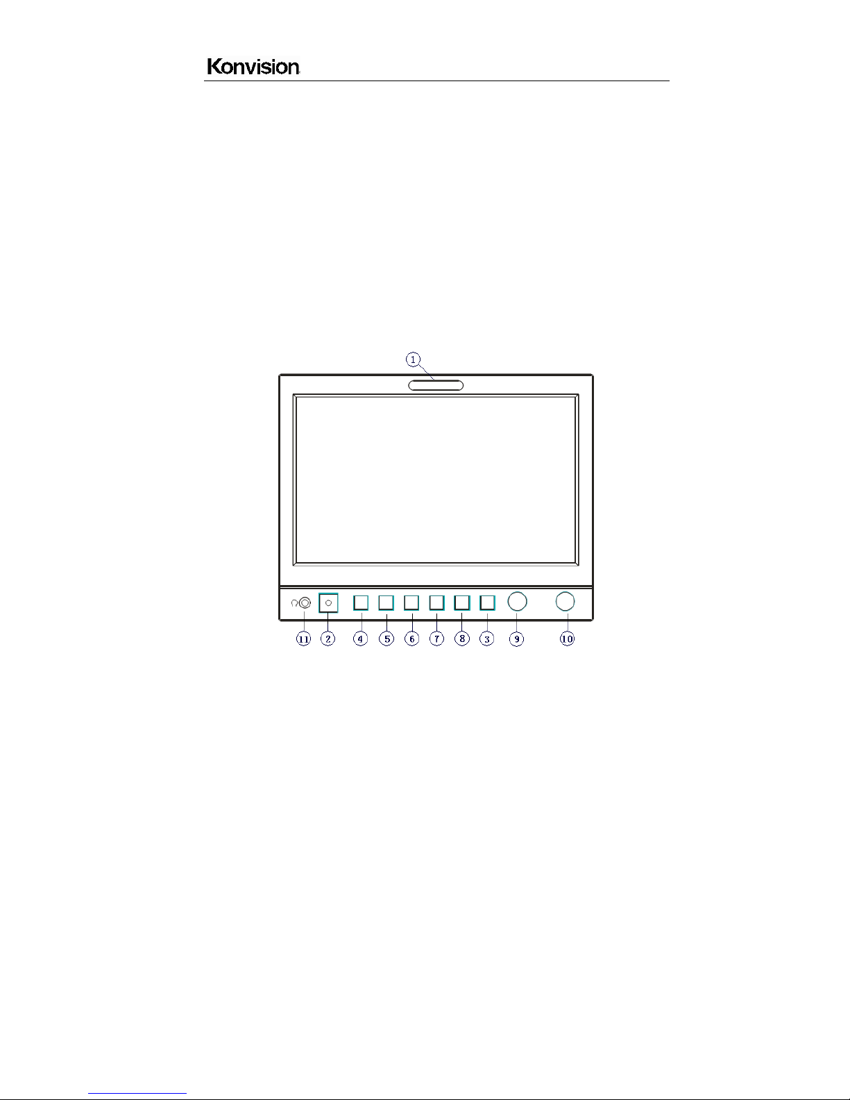
KVM-7050W front view:

Shenzhen Konvision Technology Co,.Ltd www.konvision.com
10
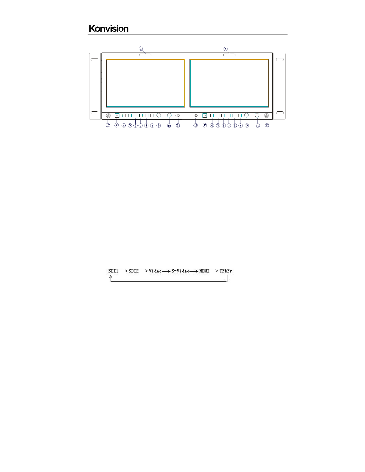
KVM-9050W front view:
KVM-7050W-2 front view:
Shenzhen Konvision Technology Co,.Ltd www.konvision.com
11
KVM-9050W-2 front view:
(1)Tally Indicator
This tally indicator is controlled by RS232 port, with two colors, red and green.
(2) Power Button and Indicator
When the external DC power supply with electricity, the indicator light is red. Press this
POWER button to power on the monitor, and the indicator light turns blue. Press this
button again to turn off the monitor.
(3)MENU Button
Press this button to display the OSD menu, and press it again to exit the menu.
Clear the markers.
Clear display mode.
Turn off the shortcut menu.
(4)SOURCE Button
Press this button to select the input signal sources.
Selection list as below:

Shenzhen Konvision Technology Co,.Ltd www.konvision.com
12
(5)MARKER Button
When the screen showing single picture, press this button for shortcut function: safety
area.
(6)WFM/VCTR Button
Only for SDI signal input, continuously press this button for shortcut functions: Y
waveform, CbCr waveform, Vector, Histogram, RGB Histogram, full screen waveform.
(There is no histogram and RGB histogram when under 480I, 576I signal status)
(7)EXPOSE Button
Only for SDI signal input, continuously press this button for shortcut functions: false color,
zebra.
(8) FOCUS
Continuously press this button for shortcut functions: Focus assist and Part Zoom In.
When it is SDI signal input, press FOCUS, active focus assist function, meanwhile, the
sharpest edge of image will mark in red. If press it again, it will appear a green box under
this status, rotate the VOLUME knob and/or IMAGEADJ knob can adjust the position of
the green box, after you select the position you want to zoom in, press VOLUME knob or
IMAGEADJ knob, it will zoom in and display full screen. If under Part Zoom In status,
press VOLUME knob or IMAGEADJ knob, it will return to green box status. If under focus
assist and Part Zoom In status, press FOCUS, it will cancel the focus assist function, and
remain part Zoom In function, press FOCUS again, it will exit Part Zoom In function.
When it is HDMI, YPbPr, Video signal input, Press FOCUS, it will appear a green box
directly, rotate the VOLUME knob and/or IMAGEADJ knob can adjust the position of the
green box, after you select the position you want to zoom in, press VOLUME knob or
IMAGEADJ knob, it will zoom in and display full screen. Press the VOLUME knob or
IMAGEADJ knob again, it will return to green box status. If under green box status, press
FOCUS, the green box will disappear. If under Part Zoom In function, press FOCUS, it
will exit this function. (There is no focus assist function if signal input is HDMI, YPbPr, and
Video)
(9)VOLUME Knob
This knob is encoder with key switch functions.

Shenzhen Konvision Technology Co,.Ltd www.konvision.com
13
Turn this knob for Left and Right operation.
Press this knob for two shortcut functions: speaker volume and Headphone volume.
Volume: turn the knob to adjust speaker volume.
HD Volume: turn the knob to adjust headphone volume.
(10)IMAGE ADJ Knob
In OSD menu, turn this knob for Up and Down operation.
Press this knob for shortcut functions: Brightness, Contrast and Chroma.
Turn the knob adjust the value of Brightness, Contrast and Chroma respectively.
(11) Headphone
Headphone 3.5mm output.
(12)Speaker: Built-in Stereo speaker.

Shenzhen Konvision Technology Co,.Ltd www.konvision.com
14
B: Rear View
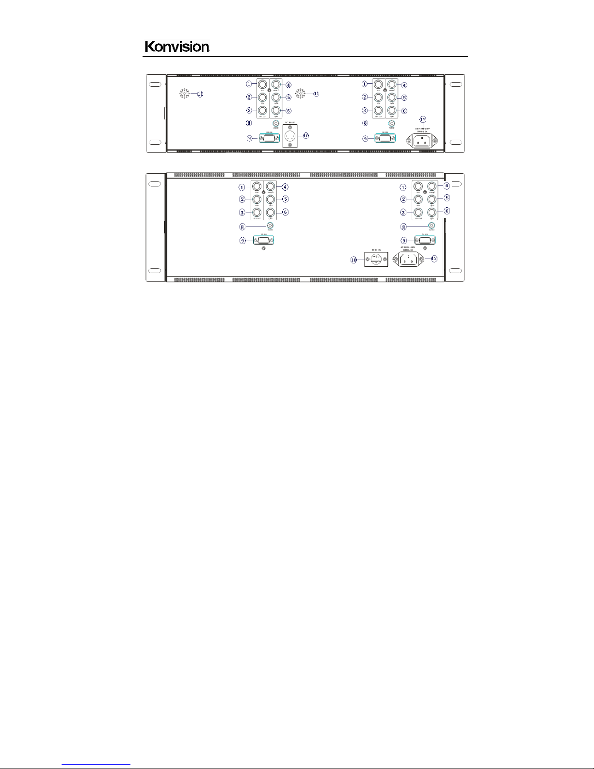
KVM-7050W rear view:
KVM-9050W rear view:
Shenzhen Konvision Technology Co,.Ltd www.konvision.com
15
KVM-7050W-2 rear view:
KVM-9050W-2 rear view:
(1) SDI1 input: 3G/HD/SD-SDI auto detect.
(2) SDI2 input: 3G/HD/SD-SDI auto detect.
(3) SDI Loop through: SDI Re-clock loop through, without enervation.
(4) Video/YPbPr-Y input: Composite video in and Y input of YPbPr component signal.
(5) YC-Y/Pb input: Y input of YC signal and Pb input of YPbPr signal.
(6) YC-C/Pr input: C input of YC signal and Pr signal of YPbPr signal.
(7) HDMI input.
(8) AUDIO in: Analogue audio in.
(9) RS-232: For remote control/GPI, Tally indicator control and Marker On/off, etc.
For software upgrade.
(10) DC 12V IN: wide range DC input voltage 7-20V.
(11) Speaker: Stereo audio output
(12) AC-IN 100-240V Power supply

Shenzhen Konvision Technology Co,.Ltd www.konvision.com
16
● OSD Menu
○
1 Menu structure:
Picture
Picture Mode
Brightness
Contrast
Sharpness
Colour
Hue
Colour Temp
Img. Adj
Image Size
Scan Mode
DVI YUV Color Space (only for HDMI signal)
CTI (Color Transient Improvement)
Ntsc 7.5IRE (only for video signal)
Gray Mode
Blue Mode
Fast Mode
H/V Delay (only for SDI1 signal)
Setup
OSD Settings
Transparency
OSD Timeout
Marker Setting
Marker Enable
Marker Select
Center Marker

Shenzhen Konvision Technology Co,.Ltd www.konvision.com
17
Safety Area
Marker Level
Marker Mat
Part Zoom in
Format Display
Power Saving
Screen Saver
Factory Reset
Audio
Volume
Headphone Volume
Audio Level Meter (only for SDI signal)
Audio Out Channel (only for SDI signal)
Audio Display Mode (only for SDI signal)
PIP/PBP
Layout
Main Window Source
Second Window Source (for PIP/PBP)
PIP Size (only for PIP)
PIP Position (only PIP)
Alpha Blend (only for PIP)
Swap (for PIP, PBP)
UMD Display
UMD ID
UMD Main Window Char
UMD Second Window Char (for PIP, PBP)
Scope (only for SDI signal)
Waveform Mode
Waveform Alarm
Waveform Scale

Shenzhen Konvision Technology Co,.Ltd www.konvision.com
18
Histogram Mode
Vector
Vector Scale
Zebra
Zebra Level
Pixel Measure
False Color
Focus Assist
H Flip
Status
Source & Format
Fh
Fv
Color Temp
Image Size
Scan Mode
CTI
Screen Saver
Power Saving
○2 Menu Operation
1. Press the POWER button to switch on the monitor; Press the Menu button, the
main menu will be displayed on the screen, and press the MENU button again to
exit the menu.
2. In the main menu, turn the VOLUME knob to select different items: Picture,
Img.Adj, Setup, PIP/PBP, (Scope) and Status.
3. Turn the IMAGEADJ knob, to enter or exit sub-menu. If sub-menu items are
marked by the drop-down sub-menu group with icon
; turn it to open or close
the drop-down sub-menu group.
4. In sub-menu, turn the VOLUME knob to select the sub-menu item operation.

Shenzhen Konvision Technology Co,.Ltd www.konvision.com
19
5. When the menu window is not enough to show all the sub menu items, it will show
up/down arrow
for the rest items.
○3 Menu Item Description
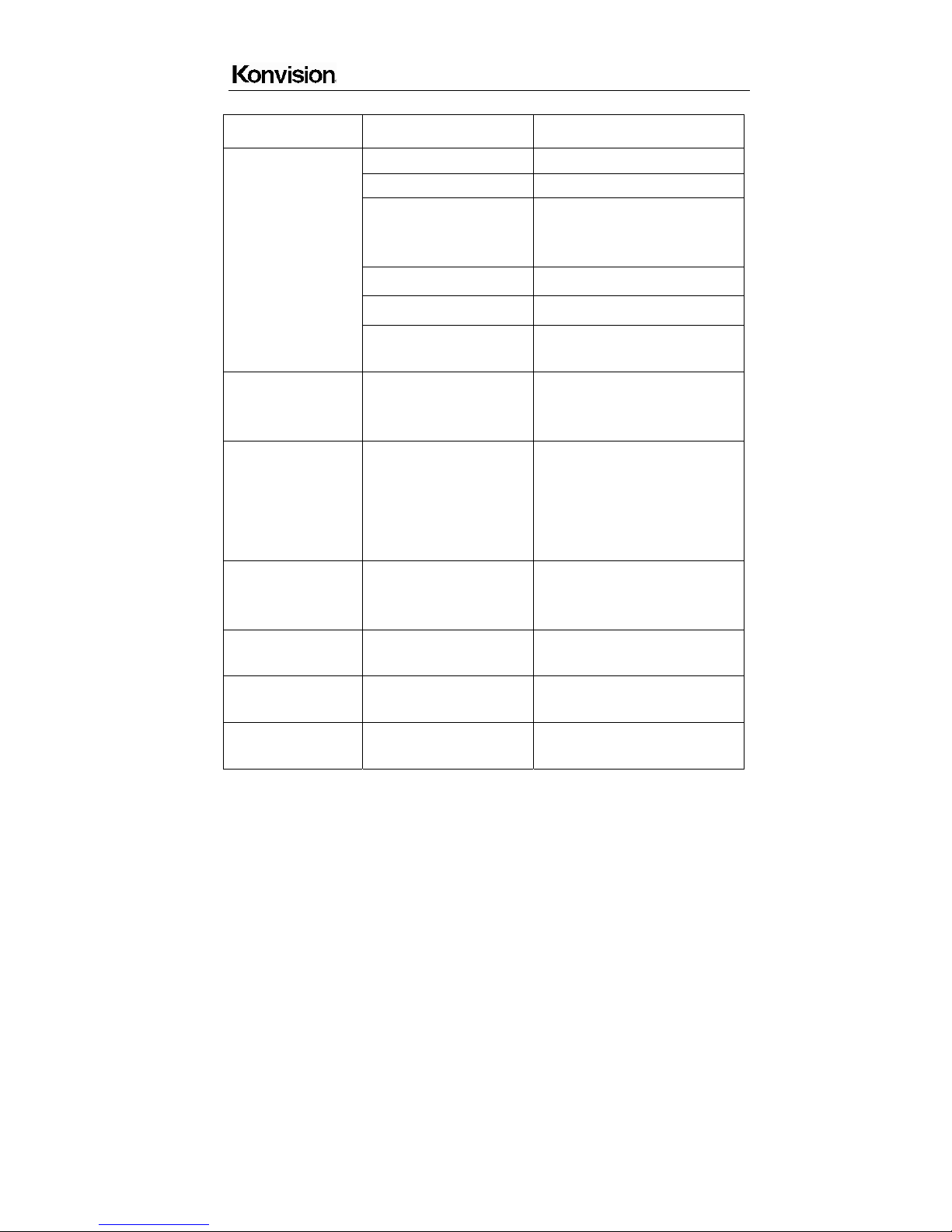
A. Picture
Menu item Setting Description
Picture mode DYNAMIC
STANDARD
SOFT
Custom
The parameters of brightness,
contrast, sharpness, color, hue in
three modes: dynamic, standard,
soft.
Custom is for user definition
Brightness
0-100
Brightness Adjustment
Contrast
0-100
Contrast Adjustment
Sharpness
0-15
Sharpness Adjustment
Colour
0-100
Saturation Adjustment
Hue
0-100
Color Adjustment
Colour Temp 3200K
5600K
6500K
9300K
Custom:
Red Gain 0-255
Green Gain 0-255
Blue Gain 0-255
Red offset 0-255
Green offset 0-255
Blue offset 0-255
Four modes of the fixed color
temperatures selection (3200K,
5600K, 6500K, 9300K) and a
custom selection.
"Custom" is for user definition, to
adjust the gain value and offset
value of Red, Green and Blue. It
will save the color temperature
setting automatically.
Shenzhen Konvision Technology Co,.Ltd www.konvision.com
20
B. Img. Adj
Menu Item Setting Description
Image Size
FILL ASPECT Original ratio of the signal source
Full Screen Full screen image
1:1
At 1:1 pixel-to-pixel display. It is
invalid in PIP, sub-screen and
PBP mode
16:9 16:9 aspect ratio
4:3 4:3 aspect ratio
DSLR Full screen for Canon 5D II via
HDMI input
Scan Mode 100% Scan
Over Scan 5%
Under Scan 5%
100% Image display
95% Image display
105% image display
DVI/ YUV
Color Space
ON
OFF
DVI input signal color space
change to YUV.
DVI input signal color space is
RGB
(For HDMI signal only)
CTI ON
OFF
Color Transient Improvement, for
better color transition
CTI off
Ntsc 7.5IRE ON
OFF
(For video signal only)
Gray mode ON
OFF
Monochrome mode with black
and white image
Blue Mode ON
OFF
Display in Blue only
Shenzhen Konvision Technology Co,.Ltd www.konvision.com
21
Fast Mode ON
OFF
Interlaced scan without
converting into progressive scan
H/V Delay ON
OFF
Display horizontal and vertical
blanking area of SDI1 input
signal
C. Setup
Menu Item Setting Description
OSD Settings:
Transparency
OSD Timeout
0-100
1-30
Menu background from opaque
to completely transparent
selection
Menu disappear time when no
button operation
Marker
setting
Marker
Enable
ON
OFF
All markers on
All markers off
Marker
Select
OFF
4:3
16:9
15:9
14:9
13:9
1.85:1
2.35:1
NO marker display
Marker display 4:3
Marker display 16:9
Marker display 15:9
Marker display 14:9
Marker display 13:9
Marker display 1.85:1
Marker display 2.35:1
Center
Marker
ON
OFF
Display center mark
No display center mark
Safety
Area
OFF
80%
85%
No Safety Area display
80%Safety Area display
85%Safety Area display

Shenzhen Konvision Technology Co,.Ltd www.konvision.com
22
88%
90%
93%
88%Safety Area display
90%Safety Area display
93%Safety Area display
Marker
Level
OFF
Translucency
Half
High
Middle
Low
No marker line
Marker line is grey
Marker line is white
Marker line is black
Marker line is grey
Maker line is white
Marker
Mat
OFF
Half
Black
Transparency
Turn off Fill up the background
beyond marker
Background beyond marker filled
up with grey,
Fill up with black
Background beyond marker
transparent
Part Zoom in <Right>Enter, <PIP>Part
Zoom in
Zoom in any part of the picture, to
watch picture details more
clearly, and assist for focus.
Format Display OFF
ON
Auto
Turn off the display info of signal
format.
Turn on the display info of signal
format.
Automatically display info of
signal format when signal
changes, disappear after 4s.
Power Saving ON
OFF
Enter power-saving mode, the
system will switch off some
functions when the main input is

Shenzhen Konvision Technology Co,.Ltd www.konvision.com
23
without signal more than 10
minutes. This feature is invalid in
PIP/PBP status.
Screen Saver ON
OFF
The system will enter screen
saver mode when the main input
is without signal. This feature is
invalid in PIP/PBP status.
Factory Reset <Right> to Factory Reset Turn right the VOLUME knob, the
system restore to factory
setting
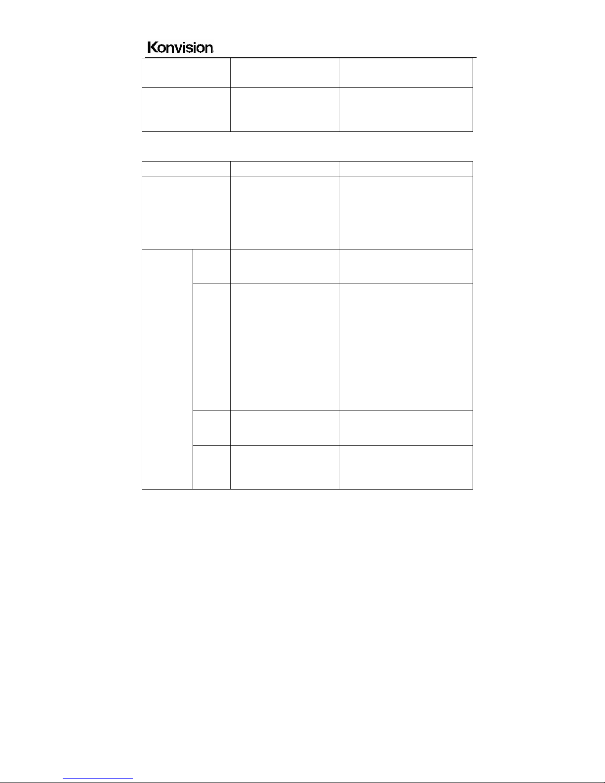
D. Audio
Menu item Setting Description
Volum e
0-100
Speaker volume adjustment
Headphone Volume
0-100
Headphone volume
adjustment
Audio Level Meter
(only for SDI signal)
ON
OFF
Turn on/off audio level meter
display
Audio Out Channel
(only for SDI signal)
CH1&CH2
CH3&CH4
CH5&CH6
CH7&CH8
SDI embedded audio CH1 &CH2
SDI embedded audio CH3 &CH4
SDI embedded audio CH5 & CH6
SDI embedded audio CH7 & CH8
Audio Display Mode
(only for SDI signal)
Horizontal
Vertical
Audio level meter display
horizontal/vertical
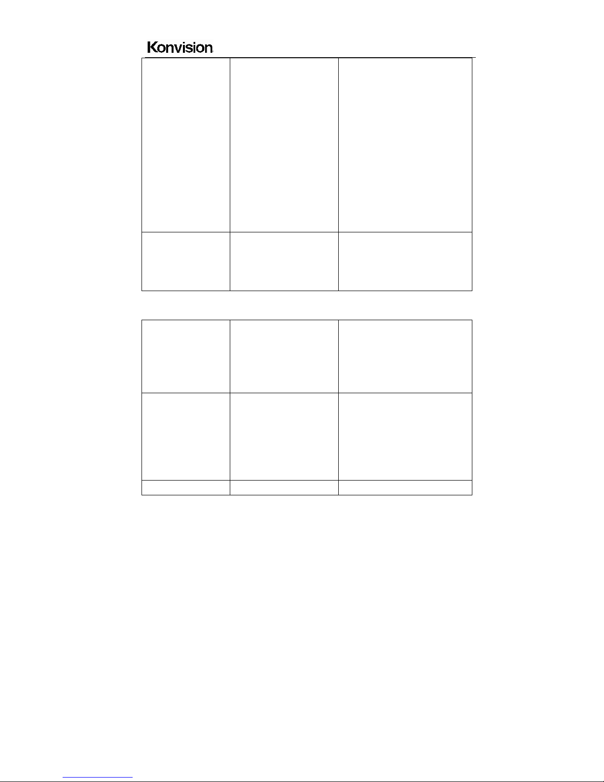
E. PIP/PBP
Menu item Setting Description
Layout Single
Display only one signal picture on
screen

Shenzhen Konvision Technology Co,.Ltd www.konvision.com
24
PIP
Side by Side
Display two signals pictures
simultaneously on screen, the
sub picture overlay on the main
picture.
Display two signals pictures
side-by-side simultaneously on
screen, the sub picture at the
right side of the main picture.
Note: In PIP/PBP mode, one
signal is SDI, the other signal is
any other input signals (except
SDI). The two pictures should be
different signal formats.
Main Window Source Video
S-Video
YPbPr
SDI1
SDI2
HDMI
VGA
Main Window select signal input
among Video/ S-Video/ YPbPr/
SDI1/SDI2/ HDMI
(Note: YPbPr is compatible with
RGB, YCbCr, YPbPr)
Second Window
Source (this item
shows in PIP/PBP)
Video
S-Video
YPbPr
SDI1
SDI2
HDMI
VGA
Second Window select signal
input among Video/ S-Video/
YPbPr/ SDI1/SDI2/ HDMI
(Note: YPrPr is compatible with
RGB, YCbCr, YPbPr)
PIP Size (this item
shows in PIP mode)
Large
Middle
The second window is Large size
The second window is medium
size

Shenzhen Konvision Technology Co,.Ltd www.konvision.com
25
Small The second window is small size
PIP position (this
item shows in PIP
mode)
Left Top
Right Top
Center
Right Bottom
Left Bottom
Custom
The second window in the left-top
corner of screen.
The second window in the
right-top corner.
The second window in the center.
The second window in the
right-bottom corner.
The second window in the
left-bottom corner.
The second window is adjustable
by user
When the user select this option,
it will automatically pop up at the
following "H position" and "V
position" menu items
H Position
(this item shows
when PIP position
select “Custom”)
0-100
Horizontal position adjustment of
picture-in-picture’s second
window.
V Position
(this item shows
when PIP position
select “Custom”)
0-100
Vertical position adjustment of
picture-in-picture’s second
window.
Alpha Blend
(this item shows in
PIP mode)
0-100
Adjustment of PIP’s second
window and the main window
alpha blend degree. When the
value is 0, the second window is
translucent blend with the main
window; when the value is 100,

Shenzhen Konvision Technology Co,.Ltd www.konvision.com
26
the second window blend directly
to the main screen.
Swap
(this item shows in
PIP/PBP mode)
<Right> to swap two
windows
In PIP and PBP, turn right the
VOLUME knob to swap the
signal pictures between two
windows (main window and
second window).
UMD Display ON
OFF
Turn on/off the UMD display
UMD ID 000-127 UMD ID can be set any value
from 000-127. It can be used for
multidevice cascading, set
different UMD ID for different
devices. In remote control
situation, this function can be
used for distinguishing different
devices so as to remote control
different devices.
UMD Main Window
Char
xxxxxxxx It can be set at any character
in ”xxxxxxxx”. Setup process:
Select the UMD Main Window
item, press VOLUME knob, it
shows “xxxxxxxx ok”,
meanwhile, the first character
becomes red, user can select the
character you need by turning the
VOLUME knob (Left/Right),
press the VOLUME knob after
finishing first character, it will turn
Shenzhen Konvision Technology Co,.Ltd www.konvision.com
27
to the second character, select
the character you need same as
first character, it’s also applied to
other characters. After finishing
selecting the 8
th
character, press
the VOLUME knob, the “ok” will
turn red, rotate the VOLUME
knob to make the “ok” turn
yellow, press MENU to save and
exit. Only the “ok” turn yellow, it
will save successfully when press
MENU, otherwise, it will not save.
UMD Second
Window Char(this
item shows in
PIP/PBP mode)
xxxxxxxx Setting is same as UMD Main
Window Char.
F. Scope (only for SDI signal)
Waveform Mode
OFF
LUMA
CbCr
Full LUMA
Turn off the waveform mode
Display Y(luminance) waveform
Display CbCr waveform
Display Y(luminance) waveform
in full horizontal
Waveform Alarm 84%-100%
Waveform alarm can be set
at any percentage between
84%-100%, it’ll alarm when
measured waveform reach
or exceed the value you set
and mark them with red
Waveform Scale Digital Display in digital

Shenzhen Konvision Technology Co,.Ltd www.konvision.com
28
IRE Display in percentage of
luminance
Histogram Mode OFF
LUMA
RGB
Turn off the histogram mode
Display luminance histogram
Display R G B histogram
Vector ON
OFF
Turn on/off vector
Vector Scale 100%
75%
Vector 100% display
Vector zoom out to 75% display
Zebra ON
OFF
Turn on/off zebra
Zebra Level 84%-100% Zebra level can be set at any
percentage between 84%-100%,
it will alarm when measured
luminance reach or exceed the
value you set and overlay display
with red zebra stripes
Pixel Measure ON
OFF
Turn on/off pixel measure
False Color ON
OFF
Turn on/off false color
Focus Assist ON
OFF
Turn on/off focus assist
H Flip ON
OFF
Turn on/off H flip

Shenzhen Konvision Technology Co,.Ltd www.konvision.com
29
G. Status
Menu item Description
Source & Format The current window’s input signal source and resolution
Fh H frequency of the current window’s input signal
Fv V frequency of the current window’s input signal
Color Temp Current Color Temperature
Image Size Current selected image size
Scan Mode Current scan mode
CTI Color Transient Improvement mode status
Screen Saver System screen saver mode status
Power Saving System power saving mode status
Pixel Measure operating instructions:
Press MENU button, enter into menu items, rotate VOLUME knob to Scope item, and
then rotate IMAGEADJ knob to select Pixel Measure, active the pixel measure function,
rotating VOLUME knob (left/right) and/or IMAGEADJ knob(up/down) can move the large
cross, to measure any pixel position and RGB value.
This function can be used for comparison of any two pixels: enter into Pixel Measure
function. Rotating VOLUME knob (left/right) and/or IMAGEADJ knob (up/down) can move
the large cross to the first pixel, press VOLUME knob or IMAGEADJ knob to mark first
pixel with a small cross, and then rotate VOLUME knob (left/right) and/or IMAGEADJ
knob (up/down), it will appear a large cross, move it to the second pixel you want to
compare, it will display difference between the current pixel and the former marked pixel.
Measure: measurement
Current: current pixel
Ref-pos: former marked pixel
Diff: difference between the current pixel and former marked pixel

Shenzhen Konvision Technology Co,.Ltd www.konvision.com
30
Line: pixel vertical position
Sample: pixel horizontal position
Y: luminance as an absolute value (0-1023)
%: luminance level expressed as percentage (Y value/256) *100%
R%: red level expressed as percentage (red value/256) *100%
G%: green level expressed as percentage (green value/256) *100%
B%: green level expressed as percentage (blue value/256) *100%
R256: red level as an absolute value (0-255)
G256: green level as an absolute value (0-255)
B256: blue level as an absolute value (0-255)
● Factory Reset
This function is to reset the monitor to factory preset.
Please try to reset the monitor, when the following situations occur:
1. The monitor parameters are adjusted incorrect by user.
2. The monitor picture or sound is abnormal, and not due to hardware problem.
To do factory reset, please follow the below five steps:
1. Press MENU button to enter main menu.
2. Turn VOLUME knob to item Setup and select it.
3. Turn IMAGE ADJ knob to Factory Reset and select it.
4. The screen will refresh after following the instruction of turning the VOLUME knob.
5. Power off the monitor, and must wait for at least 5 seconds, then restart the monitor.
The monitor resets to factory preset.
● Remote Control
1. Hardware connection
Connect the monitor’s RS-232 serial port to the computer to remote control the
monitor by universal serial communication software.
Shenzhen Konvision Technology Co,.Ltd www.konvision.com
31
2. Software Configuration
Start communication software, configure the serial communication parameters,
sending communications test command, if the return value is correct, you can send
control command.
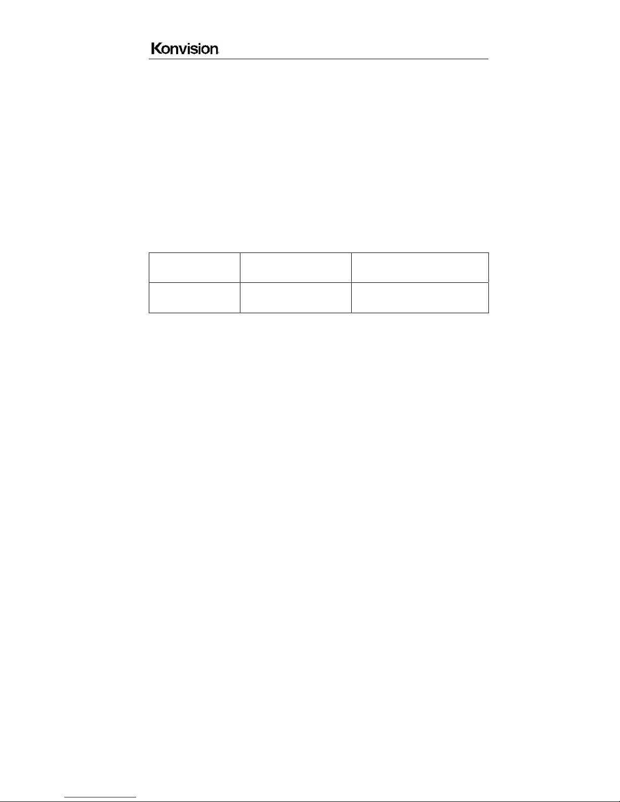
Serial port settings:
Baud Rate: 19200
Parity: None
Data bits: 8
Stop bit: 1
Flow Control: None
Communications test:
Communications test
command
Return value Description
BE EF 01 05 00 D1 FA 01
02 00 00 00
1E BE EF 01 04 00 37 3D 01 02
00 01
Return value is correct, the
communication setup is normal
Two methods of controlling tally indicator.
(1) Connect the monitor’s RS-232 serial port to the computer to remote control tally
indicator by sending commands via universal serial communication software.
(2) When Pin9 connects to GND directly
A. tally indicator will turn green while input voltage of Pin7 is between 3.3V-5V,
B. tally indicator will turn red while input voltage of Pin 8 is between 3.3V-5V.
Note: Max input voltage of Pin7 / Pin8 is 5V, otherwise it will cause damage.

Shenzhen Konvision Technology Co,.Ltd www.konvision.com
32
Shenzhen Konvision Technology Co,.Ltd www.konvision.com
33
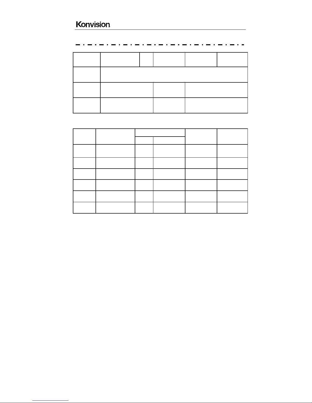
Warranty Card
User Tel Postal Code
Address
Product
Model
Serial
Number
Dealer
Purchase
Date
Maintenance Record
Date
Contents of
Reparation
Replacement parts
Repairer
User
Signature
Name Qty
This warranty card should be filled in immediately when purchasing
Please keep a proper record of this warranty card.
As the continuous improvement of the products, this will subject to change without notice
All contents on this data have been carefully checked, if there is any printing errors &
omissions or any misunderstanding, our Company reserves the right of interpretation.
 Loading...