

Page 1

RT2070 Quick Installation Guide
Wireless Local Area Network dual band USB Card
(For 802.11b/g Wireless Networks)
contents
1. Overview
1.1 Product Introduction
Thank you for choosing the RT2070 USB Adapter.
The adapter is designed to provide a high-speed and unrivaled wireless performance for your
computer. With a faster wireless connection, you can get a better Internet experience, such as
downloading, gaming, video streaming and so on.
The RT2070 USB Adapter supporting IEEE 802.11b/g 2.4GHz radio operation. The RT2070 ’s
auto-sensing capability allows high packet transfer rate of up to 54Mbps for maximum
throughput.Additionally, the RT2070 adapter has good capability on anti-jamming and supports
WEP,TKIP, AES,WPA and WPA2 encryption to prevent outside intrusion and protect your
personal information from being exposed.Featuring high performance transmission rates, simple
installation and adaptability, as well as strong security, the RT2070 USB Adapter is the perfect
solution for small office and home needs.
System Requirements
System configuration recommended is as follows:
= Windows XP/2000
= Standard USB 2.0 port
= 32MB system memory or larger
= 300MHz processor or higher
1.2 Package List
RT2070 product package contains the following items:
= 1x RT2070
= 1 x Quick Installation Guide
= 1 x UserMannual
2. Installation
This chapter mainly describes how to install RT2070 driver and Utility. The procedure is
illustrated by the example of Windows XP.
Page 2
2.1 Installation Guide
Step 1:find the setup file named ADD-RT2070 .exe, then double click ADD-RT2070 .exe to start
the installation. then Figure 2-1-1 will appear.
Figure 2-1-1 Preparing Setup
Step 2: To continue, the following Figure 2-1-2 will appear within seconds. Click Next to
continue.
Page 3
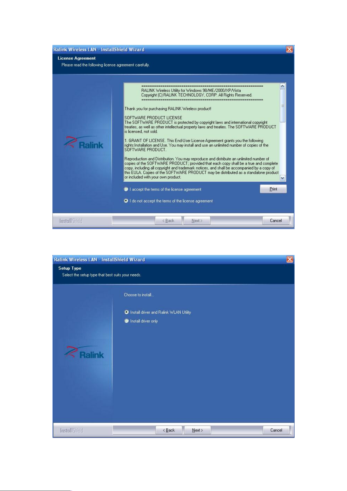
Figure 2-1-2 License Agreement
Step 3: Then you’ll see the screen as follow, you can choose what to be installed.
Page 4

Figure 2-1-3 Setup Type
Step 4: As next screen, you can select the configuration tool here.
Figure 2-1-4 Setup Type
i. If you want to install the Ralink WLAN Utility, please select the Ralink Configuration Tool and
click Next.
ii. If you only want to use the Microsoft Zero Configuration Tool to configure the wireless
connection, please select Microsoft Zero Configuration Tool and click Next.
Step 5: After that, you will see the next screen as below. Click Install to continue.
Page 5

Figure 2-1-5 Ready to Install the Program
Step 6: The following screen for installing will appear.
Page 6

Figure 2-1-6 Setup Status
Note:
While files are copying, a warning box about Windows Logo testing may pop up, please click
Continue Anyway button to continue the installation
Step 7: After the files have been successfully copied, the screen in Figure 2-1-7 will appear. Click
the Finish button to finish the wizard.
Figure 2-1-7 InstallShield Wizard Complete
After installing the driver successfully, you should see an icon (this icon might be different
color) appear in your system tray.
2.2 Uninstall Software
2.2.1 Uninstall the driver software from your PC
Step 1: Right click on My Computer, choose Manage.Shown as Figure 2-2-1-1.
Page 7

Figure 2-2-1-1
Step 2:Then the follow interface shown as figure 2-2-1-2:
figure 2-2-1-2
Step 3:Click on the Device Manager button, double-click Network Adapters, and then
right-click 802.11 USB Wireless LAN Card USB Adapter. figure 2-2-1-3.
Step 4: Click Uninstall shown in above figure 2-2-1-3, the system will uninstall the
driver software of the adapter from your PC.
Page 8

figure 2-2-1-3
2.2.2 Uninstall the utility software from your PC
Step 1: On the Windows taskbar, click the Start button, point to
All programsèRalink Wireless,and then click Uninstall-RT7x.shown as figure 2-2-2-1
Figure 2-2-2-1
Step 2: Following the Install Shield Wizard to uninstall the utility software from your PC.
3. Configuration
3.1 Configuration of Utility
RT2070 Wireless USB Adapter can be configured by its utility for Windows 2000, XP.
This section will take the configuration in Windows XP for example and guide you to configure
your wireless adapter for wireless connectivity with trustable data security encryption features.
The configuration steps in Windows 2000 & XP are similar. For the configurations in
Windows 2000, please refer to the instructions in Windows XP.
Page 9

Note: If your OS is Windows XP, you can use Windows XP to configure the wireless network
settings.(To use this function, you must upgrade the OS with sp2).
Is the Utility running?
After the Adapter's driver and utility has been installed, the adapter’s tray icon will
appear in your system tray. It means the utility is running on your system. If the utility does not
run,you can run the utility by clicking: Start> All Programs> Ralink Wireless> Ralink Wireless
Utility. If the icon still does not appear, the driver or utility may be installed incorrectly or the
adapter is unplugged, please try again.
Meaning of icon in different color:
: Indicates the connected and signal strength is good.
: Indicates the connected and signal strength is normal.
: Indicates that it is not yet connected.
: Indicates that a wireless NIC can not be detected.
Indicates that the connection and signal strength is weak.
If you want to use Windows XP to configure wireless network settings, just right-click the icon
at the bottom of the screen, and click Use Zero Configuration as Configuration utility to
switch the utility.
Connect your PC to a AP through wireless
Suppose there is a AP with SSID as test_123, Encryption is WEP, pre-shared key is:12345
Also suppose the utility is now running.
Step 1:double click the icon in your system tray
Step 2:the follow interface will be shown,figure 3-1-1.
Page 10

Figure 3-1-1
Step 3:choose the one with SSID as test_123, and click Connect button.shown as figure 3-1-1
Step 4:then the follow interface will be shown, figure 3-1-2.
figure 3-1-2
step 5:choose type as ASCII and input pre-shared key 12345 into the follow text-area,click
OK button
step 6:then the follow interface will be shown,
Page 11

The sign means connect test_123 success
3.2 Configure with Windows XP Wireless Zero Configuration
Suppose there is a AP with SSID as test_123, Encryption is WEP, pre-shared key is:12345
Also suppose the utility is now running.
Step 1:Right click the icon on the bottom of the desktop first and you will see
Figure 3-2-1. Double click the Use Zero Configuration as Configuration utility option to
enable Wireless Zero Configuration function.
Figure 3-2-1
Step 2: After that, double click the icon , and the following Figure 3-2-2 will appear with
some available wireless network choices. You can highlight a network and then click Connect to
add to a network.
Page 12

Figure 3-2-2
Note:If you have not installed SP2 for Windows XP, the step 2 above will not be available.
Step 3: choose test_123 as figure 3-2-2, click Connect button.
Step 4: input wep pre-shared key then continue.
Step 5: If the connection is finished, the icon will display like the next screen shown.figure 3-2-3
figure 3-2-3
Page 13

This device must not be co-located or operating in conjunction with any other antenna or
transmitter
NOTE: THE MANUFACTURER IS NOT RESPONSIBLE FOR ANY RADIO OR TV
INTERFERENCE CAUSED BY UNAUTHORIZED MODIFICATIONS TO THIS
EQUIPMENT. SUCH MODIFICATIONS COULD VOID THE USER’S AUTHORITY TO
OPERATE THE EQUIPMENT.
Federal Communications Commission (FCC) Requirements, Part 15
This equipment has been tested and found to comply with the limits for a class B digital device,
pursuant to part 15 of the FCC Rules. These limits are designed to provide reasonable protection
against harmful interference in a residential installation.
This equipment generates, uses and can radiate radio frequency energy and, if not installed and
used in accordance with the instructions, may cause harmful interference to radio communications.
However, there is no guarantee that interference will not occur in a particular installation. If this
equipment does cause harmful interference to radio or television reception, which can be
determined by turning the equipment off and on, the user is encouraged to try to correct the
interference by one or more of the following measures:
---Reorient or relocate the receiving antenna.
---Increase the separation between the equipment and receiver.
---Connect the equipment into an outlet on a circuit different from that to which the receiver is
connected.
---Consult the dealer or an experienced radio/TV technician for help.
Regulatory information / Disclaimers
Installation and use of this Wireless LAN device must be in strict accordance with the instructions
included in the user documentation provided with the product. Any changes or modifications
(including the antennas) made to this device that are not expressly approved by the manufacturer
may void the user’s authority to operate the
equipment. The manufacturer is not responsible for any radio or television interference caused by
unauthorized modification of this device, or the substitution of the connecting cables and
equipment other than manufacturer specified. It is the responsibility of the user to correct any
interference caused by such unauthorized modification, substitution or attachment. Manufacturer
and its authorized resellers or distributors will assume no liability for any damage or violation of
government
CAUTION: To maintain compliance with FCC’s RF exposure guidelines, this equipment
should be installed and operated with minimum distance 20cm between the radiator and
your body. Use on the supplied antenna. Unauthorized antenna, modification, or
attachments could damage the transmitter and may violate FCC regulations.
MPE Statement (Safety Information)
Your device contains a low power transmitter. When device is transmitted it sends out Radio
Frequency (RF) signal.
Safety Information
In order to maintain compliance with the FCC RF exposure guidelines, this equipment should be
installed and operated with minimum distance 20cm between the radiator and your body. Use only
Page 14

with supplied antenna. Unauthorized antenna, modification, or attachments could damage the
transmitter and may violate FCC regulations.
This transmitter must not be co-located or operating in conjunction with any other antenna or
transmitter.
IEEE 802.11b/g operation of this product in the U.S.A. is firmware -limited to channels 1 through
11.
This device is intended only for OEM integrators under the following conditions:
The antenna must be installed such that 20 cm is maintained between the antenna and users, and
The transmitter module may not be co-located with any other transmitter or antenna.
As long as 2 conditions above are met, further transmitter test will not be required. However, the
OEM integrator is still responsible for testing their end-product for any additional compliance
requirements required with this module installed (for example, digital device emissions, PC
peripheral requirements, etc.).
 Loading...