


User's Manual
V3.25
Network Camera
Please read this manual carefully before you attempt to
install this product and retain it for your future reference.
1

Contents
Main Features ................................................................................................................................................6
Physical Description......................................................................................................................................
Installation.....................................................................................................................................................
Hardware Installation.............................................................................................................................12
Camera Network deployment ................................................................................................................14
Camera setup installation & Usage........................................................................................................17
Network Camera Screen and Setup Window .........................................................................................22
Operating Bar...............................................................................................................................................
Viewing the camera from your mobile phone.......................................................................................... 26
Network Camera Setting Interface............................................................................................................27
Camera .........................................................................................................................................................
Camera Setup.........................................................................................................................................
Stream Setup ..........................................................................................................................................
OSD Setup..............................................................................................................................................
Night V ision Setup (IR-CUT)................................................................................................................33
Network.........................................................................................................................................................
Wireless Setup........................................................................................................................................
TCP/IP Setup..........................................................................................................................................
PPPoE Setup ..........................................................................................................................................
DDNS Setup...........................................................................................................................................
UPNP Setup ...........................................................................................................................................
Alarm .............................................................................................................................................................
Digital I/O Setup....................................................................................................................................
Motion Detection ...................................................................................................................................
Schedule Setup.......................................................................................................................................
Alarm Management ................................................................................................................................
Periodic Sending....................................................................................................................................
Buffer Management ............................................................................................................................... 50
Alarm Server ................................................................................................................................................
FTP Server .............................................................................................................................................
e-Mail Server..........................................................................................................................................
HTTP Server..........................................................................................................................................
SD Functions................................................................................................................................................
Record on Alarm....................................................................................................................................
Snapshot on Alarm.................................................................................................................................
Continuous Record.................................................................................................................................
Snapshot at Interval................................................................................................................................
SD FTP Sending.....................................................................................................................................
Browse SD Card.....................................................................................................................................
Format SD Card.....................................................................................................................................
Tools ..............................................................................................................................................................
System Identity ......................................................................................................................................
User Management..................................................................................................................................
Date & Time ...........................................................................................................................................
Backup or Reset.....................................................................................................................................
Firmware Upgrade .................................................................................................................................
SPEEDREAD YOUR NETWORK CAMERA...........................................................................................67
Wizard....................................................................................................................................................
System....................................................................................................................................................
Support...................................................................................................................................................
Reboot....................................................................................................................................................
ADVANCED SETTINGS.............................................................................................................................69
Port Forwarding .....................................................................................................................................
Proxy Server Setting ..............................................................................................................................70
12
24
29
29
30
32
34
34
36
37
38
40
43
43
43
45
46
48
51
51
52
53
54
54
56
57
58
59
60
61
62
62
63
64
65
66
67
68
68
68
69
9
2

Reset the camera ............................................................................................................................... ..... 71
DEFAULT SETTINGS.................................................................................................................................
SPECIFICATIONS.......................................................................................................................................
72
76
TROUBLESHOOTING ...............................................................................................................................77
GLOSSARY OF TERMS............................................................................................................................78
3

INTRODUCTION
Thank you for your interest and support in our product and purchasing this outdoor camera. The camera can be
accessed remotely, and controlled from any PC/laptop over the Intranet or Internet via web browser. The
user-friendly installation procedure and intuitive web-based interface offer easy integration with your LAN
environment or WiFi system. Meanwhile, the IP66-rated integrated housing shields the camera from dust and
water, allowing it to be applied in the harsh weather conditions of outdoor environments.the camera also comes
with a lot of useful alarm tool for notice user any situation. We feel confident that you will be pleased with the
quality and features of this product.
Notice
This product may cause interferences with other wireless equipment that operates at 2.4GHz ISM band. Please
turn off one of the equipments to eliminate the interference.
Product Assurance
This camera will emit electromagnetic wave, just like other wireless products, but its transmitting power is
less than other wireless products such as mobile phones. The 2.4GHz wireless camera meets wireless
frequency security standards and recommended indexes while working. These standards and indexes are
certificated by academic organization and represent the cogitative research of the scientific workers who
continuously explore and annotate the involved fields. So we believe that our products are safe for
customers.
Approval Information
All our products meet the requirements of approval FCC or CE, and are granted the FCC or CE
certification. They are authorized to bear FCC or CE mark.
FCC
This equipment has been tested and found to comply with the limits for a Class B digital device, pursuant to
Part 15 of the FCC rules. These limits are designed to provide reasonable protection against harmful
interference in a residential installation. This equipment generates, uses and can radiate radio frequency
energy and, if not installed and used in accordance with the instructions, may cause harmful interference to
radio communications. However, there is no guarantee that interference will not occur in a particular
installation. If this equipment does cause harmful interference to radio or television reception, which can be
determined by turning the equipment off and on, the user is encouraged to try to correct the interference by
one or more of the following measures: -Reorient or relocate the receiving antenna. -Increase the separation
between the equipment and the receiver. -Connect the equipment into an outlet on a circuit different from
that to which the receiver is connected. -Consult the dealer or an experienced radio/TV technician for help.
This device complies with Part 15 of the FCC Rules. Operation is subject to the following two conditions:
(1) This device may not cause harmful interference, and
(2) this device must accept any interference received, including interference that may cause undesired
operation Changes and modification not expressly approved by the manufacturer or registrant of this
equipment can void your authority to operate this equipment under Federal Communications Commissions
rules.
CE
This product complies with standards including Low Voltage Device Directive 73/23/EEC; EMC
Directive 89/336/EEC and R&TTE Directive 1999/5/EC. It passed the subject tests by the authority
concerned and is authorized to bear CE mark.
4

Restrictions
1. DO NOT use this product to violate one's privacy. Monitoring one's activities without consent is illegal
and this product is not designed and manufactured for such purpose.
2. DO NOT put this product near any medical equipment. Radio waves might potentially cause breakdown
of electrical medical equipment.
3. This product should be placed at least 1 foot away from any heart pacemaker. Radio waves might
potentially influence heart pacemaker.
4. DO NOT use this product for any illegal activities. It is the user’s responsibility to ensure that the
usage of this camera is of a legal nature.
Maintenance
1. Ensure that the camera and its power source have sufficient ventilation;
2. Do not shake, strike or drop the product;
3. Keep the camera dry and dustless and avoid exposing it to direct sunlight;
4. Do not place the product near any magnetic objects;
5. Avoid putting the product in places where there is constant temperature and humidity change;
6. Keep the product away from heat sources;
7. Do not use the camera near aggressive chemicals;
8. Do not use this camera near water;
9. Do not use the camera in the places which are enclosed by metal. The surrounding metal may shield
the electromagnetic waves, and result in failure of signal reception;
10. Please obey the local government's environment protection policy;
11. Please turn off the power when left unused;
12. Do not disassemble or attempt to repair the camera; doing so might cause damage to the product.
5

Main Features
Easy Installation
The camera comes with built-in Wireless (IEEE802.11b/g) capability and a Web Server, therefore there
is no need to install a driver. The setup CD-ROM includes the Camera Setup software, User Manual
and Quick Installation Guide.
With industry standard automatic configuration-UPnP(Universal Plug and Play), your PC will discover and
connect to your camera automatically. Once connected, using a simple Web browser you can see what the
camera sees from anywhere in the world!
The camera can be either wall-mounted or ceiling-mounted using the supplied stand. It can also be
placed on a desktop using the supplied stand, thus providing a flexible installation solution.
PoE Function
The Network Camera is with POE function, which allows it to be powered via a single Ethernet cable.
you do not need to use the power plug.but your switch/router must be support PoE.
802.11b/g Wireless LAN Connection Available
The camera is designed to not only work with your existing wired network but also with standard 802.11b/g
wireless devices, allowing the flexibility to operate the camera wirelessly. The camera utilizes SSID filtering,
powerful 64/128 bit WEP and new security standard WPA encryption to protect you from illegal intrusion.
3GPP Mobile Surveillance
The camera provides the ability to view the cameras monitored through your mobile phone as a live video
stream, it supports the telecommunications standard of 3GPP streaming format. All 3G enabled mobile devices
and most 2G phones that support the streaming standard of 3GPP are compatible.
Simultaneous High-Speed MPEG-4 and Motion JPEG
The camera allows live the MPEG-4 and Motion JPEG streams simultaneously. The camera features MPEG4
compression which compresses the video to make transmission faster and more efficient. The MPEG4 and
MJPEG image can be transmitted at 30 frames per second.
Simultaneous HTTP and RTSP streaming
The camera support HTTP and RTSP/RTP/RTCP protocol, and provide multiple HTTP and RTSP streams
simultaneously.
Audio Transmission
The camera comes with a built-in microphone for audio monitoring as well as video monitoring. Sound
captured by the camera is transmitted to the client’s PC.
Snapshot and Recording
You can capture a still image of the camera view on your PC and save the image as JPG or BMP format file.
You also can record the video and audio captured by the camera on your PC and save as an ASF format file.
6

Motion Detection Function
The camera can detect changes in the image being monitored. Once a change occurs it will send an email to
up to 3 email addresses with a video file or snapshot attached. The video file or snapshot can also be
uploaded to an FTP server. In addition the camera can be configured to send images at regular intervals.
OSD Function
OSD (On Screen Display) function can display system name, date and time, and user-defined on screen.
Authentication
An authentication window requires you to enter the user ID and password. Password security can prevent
unregistered users from accessing your camera. Users can select Basic Authentication method or Digest
Access Authentication method.
Multi-Client Access
The camera allows up to 16 users to view the video simultaneously. Please note that it is possible that as the
number of simultaneously connected users to camera increases, the overall motion performance will decrease.
Infrared Night Vision (IR-CUT)
The camera built-in IR-Cut which is prevent the image to happen color cast during daytime ,it can be switching
and filter infrared light in day/night.
The camera utilizes 12 infrared LED to provide high light in darks environment .when the environment is dark,
the LED will be opened automatically due to a photosensitive component, and the moving images will be
changed to Black and White. Users can monitor clearly the things within 15 meters distance. Users also can
select open or close the infrared LED manually, and select whether change the images to black and white or
color automatically.
7

Adapter
This product conforms with the authenticated AC adapter. The adapter is marked with one or more of the
following:
Note: When using the power adapter, make sure the rating voltage on it is compatible with that of the device
to avoid potential damages resulting from incorrect usage of power supply.
PC System Requirements
The PC (Personal Computer) and the network must meet the following technical specifications for camera to
work properly.
1. Processor: Intel Pentium III, 1GHz or Higher (Pentium IV, 2 GHz or Higher
recommended)
2. RAM: 256 MB or more
3. Color Monitor: Suggest at least 800x600 and the latest driver for the Display Adapter
4. OS(Operating System): Windows 2000/XP/Vista
5. Web Browser: Internet Explorer Version 5.0 or above, DirectX 9.0c or later
6. Network Protocol: TCP/IP network protocol installed
7. Interface: 10/100 Mbps Ethernet® card/Wireless Network card for your network
connection
8. Other: CD-ROM Drive
8
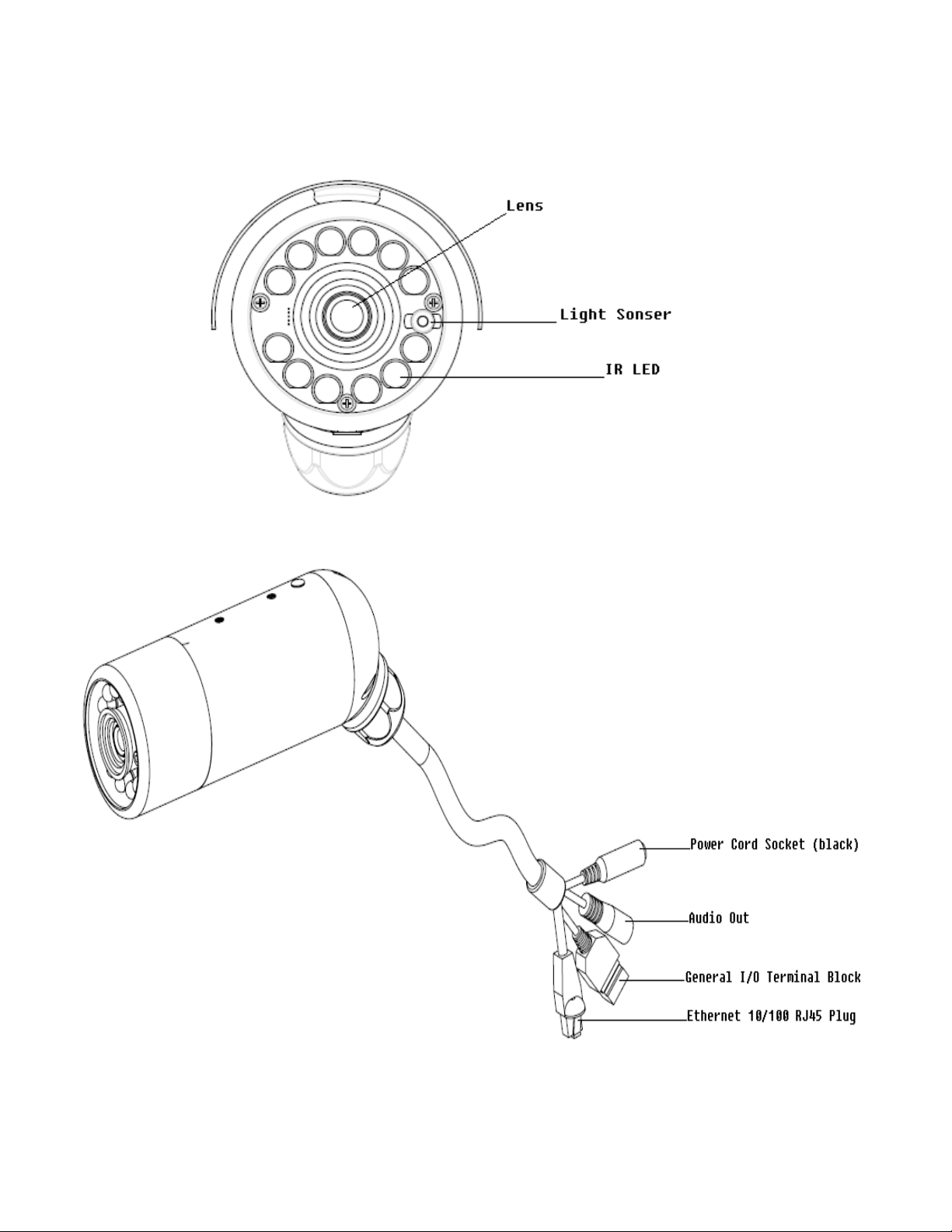
Physical Description
Front panel
Connectors
9
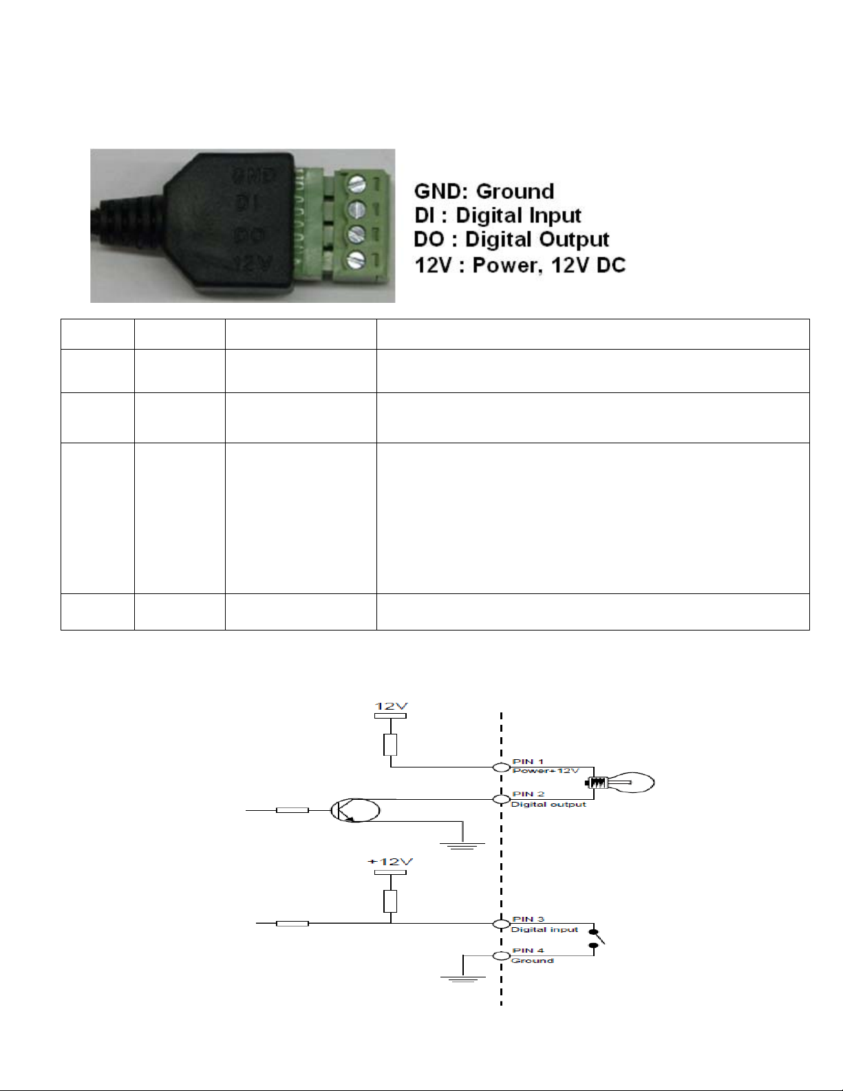
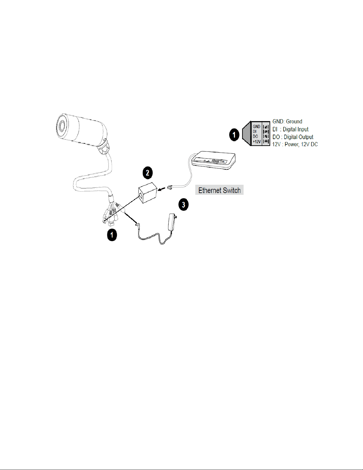
Genneral I/O Terminal Block
This Network Camera provides a general I/O terminal block which is used to connect external input / output devices. The pin definitions are
described below.
Pin No. Pin Name Function Description
4 GND Ground
This is a signal ground use for DI and DO
Connect to GND to activate or deactivate by software
3 DI Digital Iutput
setting
With a maximum load of 1A and maximum voltage of 60V
DV,this output has an open-collector NPN Darlington
transistor with the emitter to the GND pin.
2 DO Digital Output
If used with an external relay,a diode must be
connected in parallel with the load,for protection
against voltage transients.
1 12V Power +12V 12VDC ± 10%, max. 0.4A
DI/DO Diagram
Please refer to the following illustration for the connection method.
10
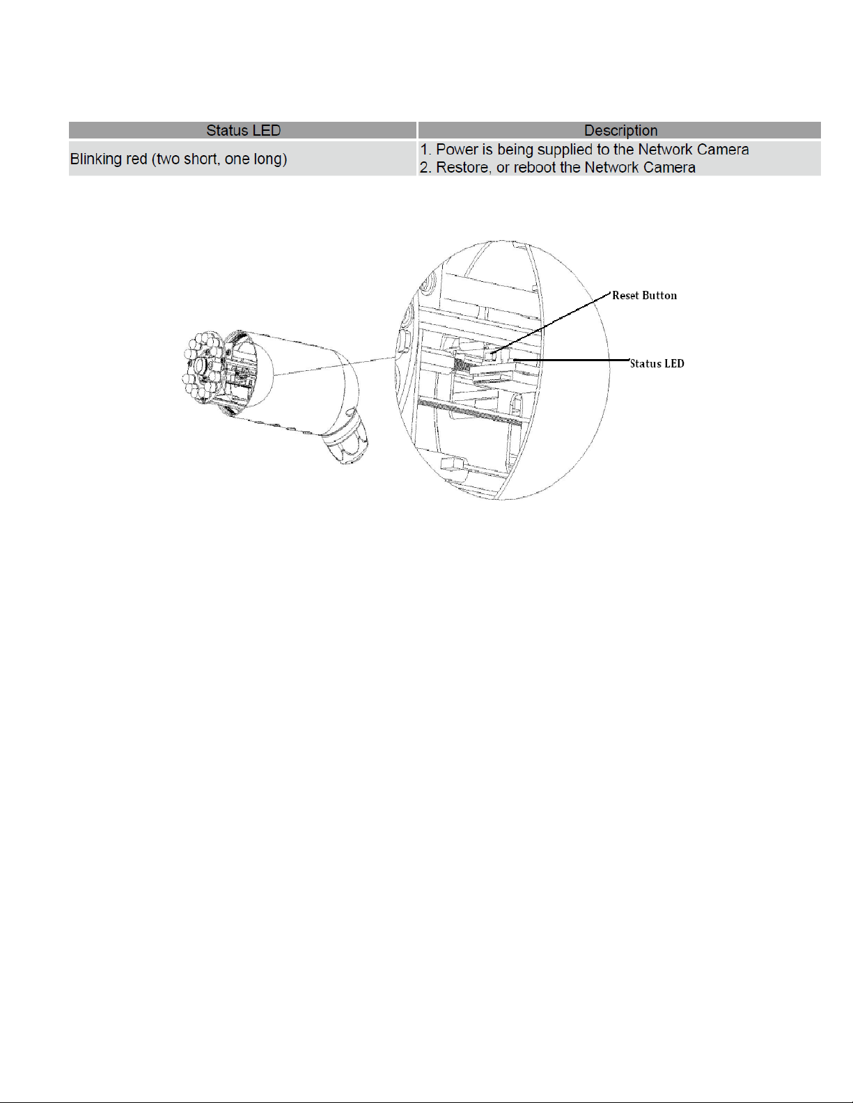
Status LED
The LED indicates the status of the Network Camera.
Hardware Reset
The reset button is used to reset the system or restore the factory default settings. Sometimes resetting the system can return the camera to normal
operation. If the system problems remain after reset, restore the factory settings and install again.
Reboot: Press and release the reset button with a paper clip or thin object. Wait for the Network Camera to reboot.
Restore: Press and hold the reset button until the status LED rapidly blinks. It takes about 30 seconds. Note that all settings will be restored to
factory default.
11
Installation
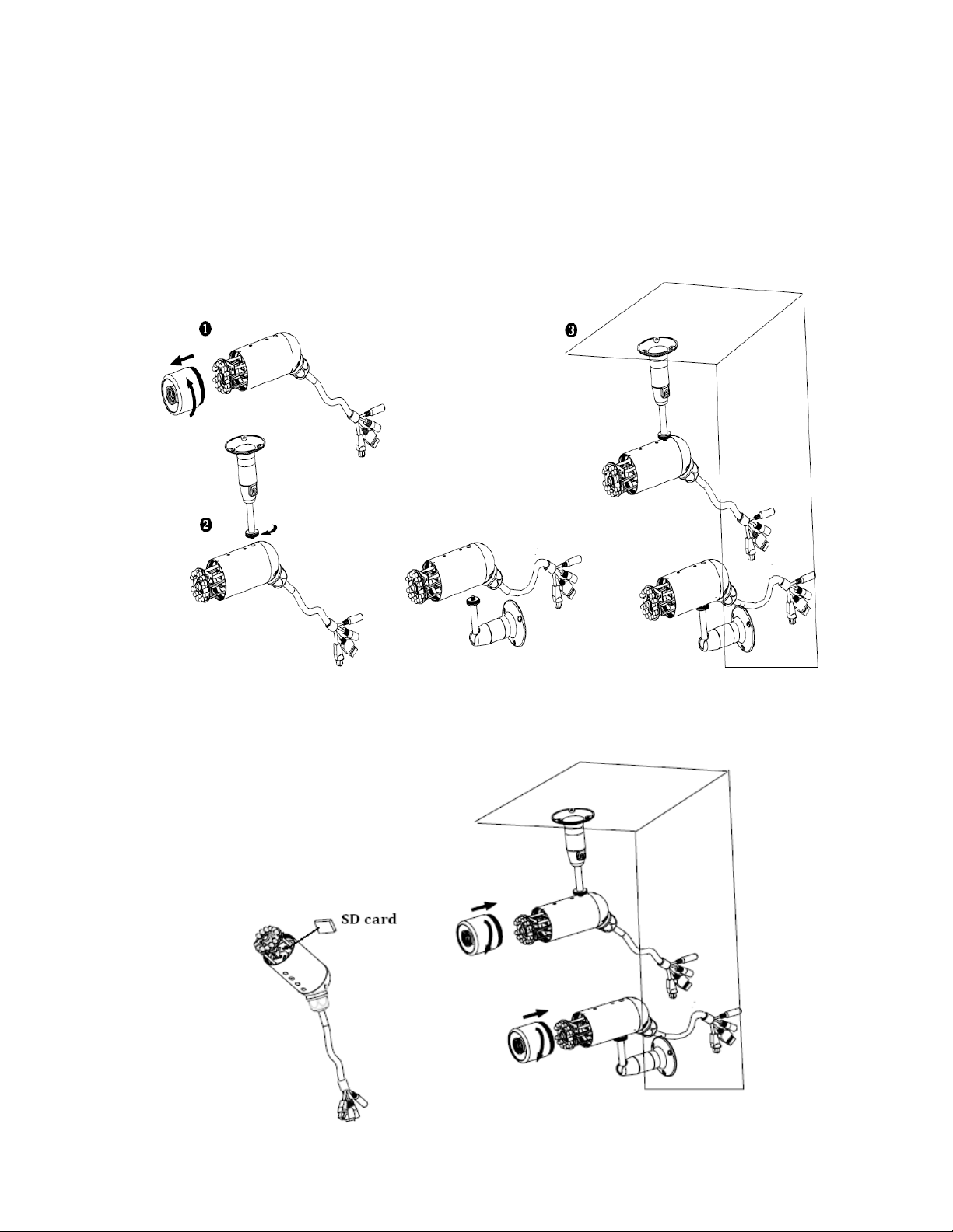
Hardware Installation
Follow the steps below to install the Network Camera:
1. Open the lens cover.
2. Secure the Network Camera to the supplied camera stand as the illustration shows.
3. Secure the Network Camera to the wall/ceiling by the supplied camera stand.
4. Open the lens cover and insert “SD card” then tighten the lens cover.
12
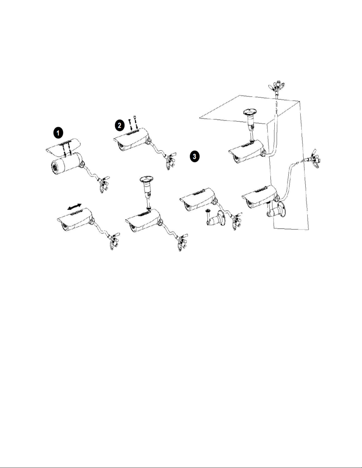
Note
If you want to use the supplied sun shield for outdoor environments, please follow the steps
below to install:
1. Attach the supplied sun shield to the Network Camera and slide it to the desired position.
2. Fix the sun shield with supplied screws and washers. (Please use different screws for ceiling mount.
3. Secure the Network Camera to the wall/ceiling by the supplied camera stand.
13
Camera Network deployment
Setting up the Network Camera over the Internet
This section explains how to configure the Network Camera to an Internet connection.
1. If you have external devices such as sensors and alarms, make the connection from the general I/O terminal block.
2. Use the supplied RJ45 female/female coupler to connect the Network Camera to a switch.use Category 5 Cross Cable when Network Camera
is directly connected to PC.
3. Connect the power cable from the Network Camera to a power outlet.
There are several ways to set up the Network Camera over the Internet. The first way is to set up the Network Camera behind a router . The
second way is to utilize a static IP. The third way is to use PPPoE.
14
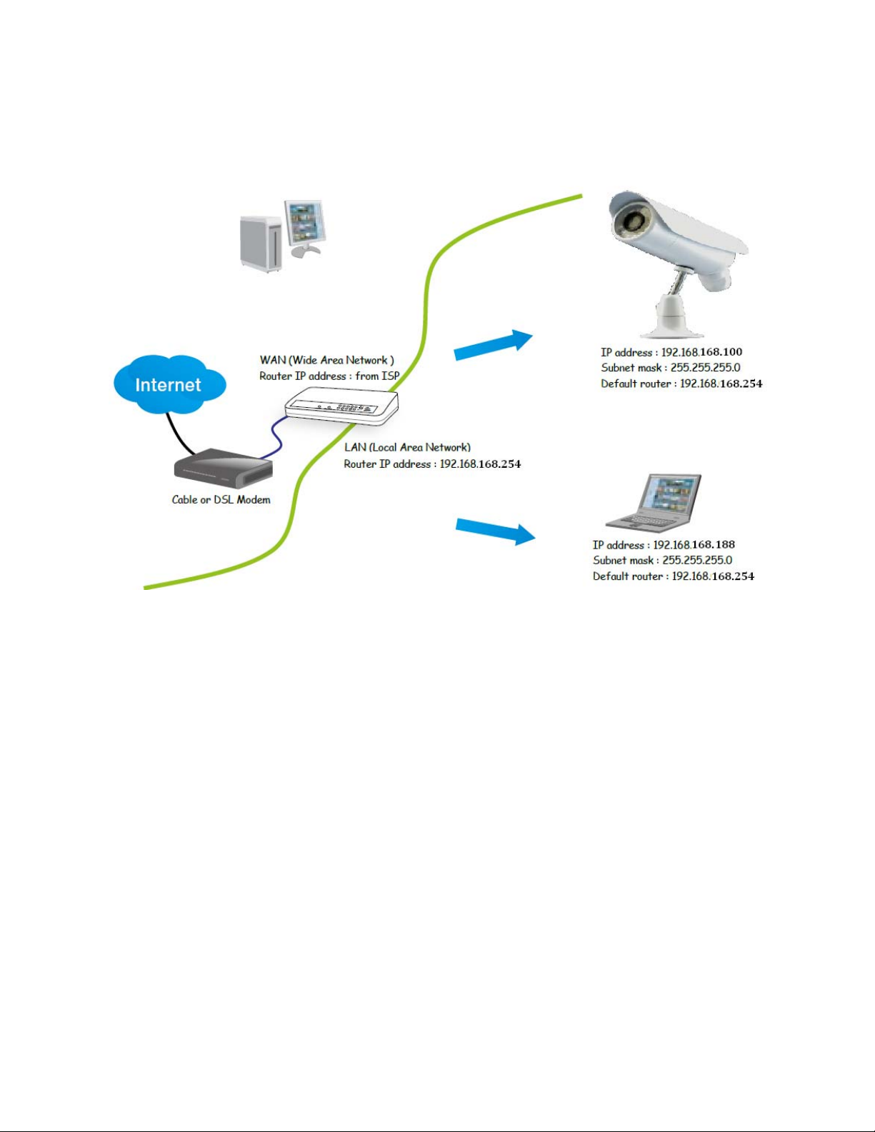
Internet connection via a router
Before setting up the Network Camera over the Internet, make sure you have a router and follow the steps below.
1. Connect your Network Camera behind a router, the Internet environment is illustrated below.
Regarding how to obtain your IP address, please refer to on page 20 for details.
2. In this case, if the Local Area Network (LAN) IP address of your Network Camera is 192.168.168.100, please forward the following ports for
the Network Camera on the router.
■ HTTP port
■ RTSP port
■ RTP port for audio
■ RTCP port for audio
■ RTP port for video
■ RTCP port for video
If you have changed the port numbers on the Network page, please open the ports accordingly on your router. For information on how to forward
ports on the router, please refer to your router’s user’s manual.
3. Find out the public IP address of your router provided by your ISP (Internet Service Provider). Use the public IP and the secondary HTTP port
to access the Network Camera from the Internet. Please refer to Network Type on page 34 for details.
Internet connection with static IP
Choose this connection type if you are required to use a static IP for the Network Camera.please refer to LAN on page 36 for details.
Internet connection via PPPoE (Point-to-Point over Ethernet)
Choose this connection type if you are connected to the Internet via a DSL Line. Please refer to PPPoE on page 37 for details.
15
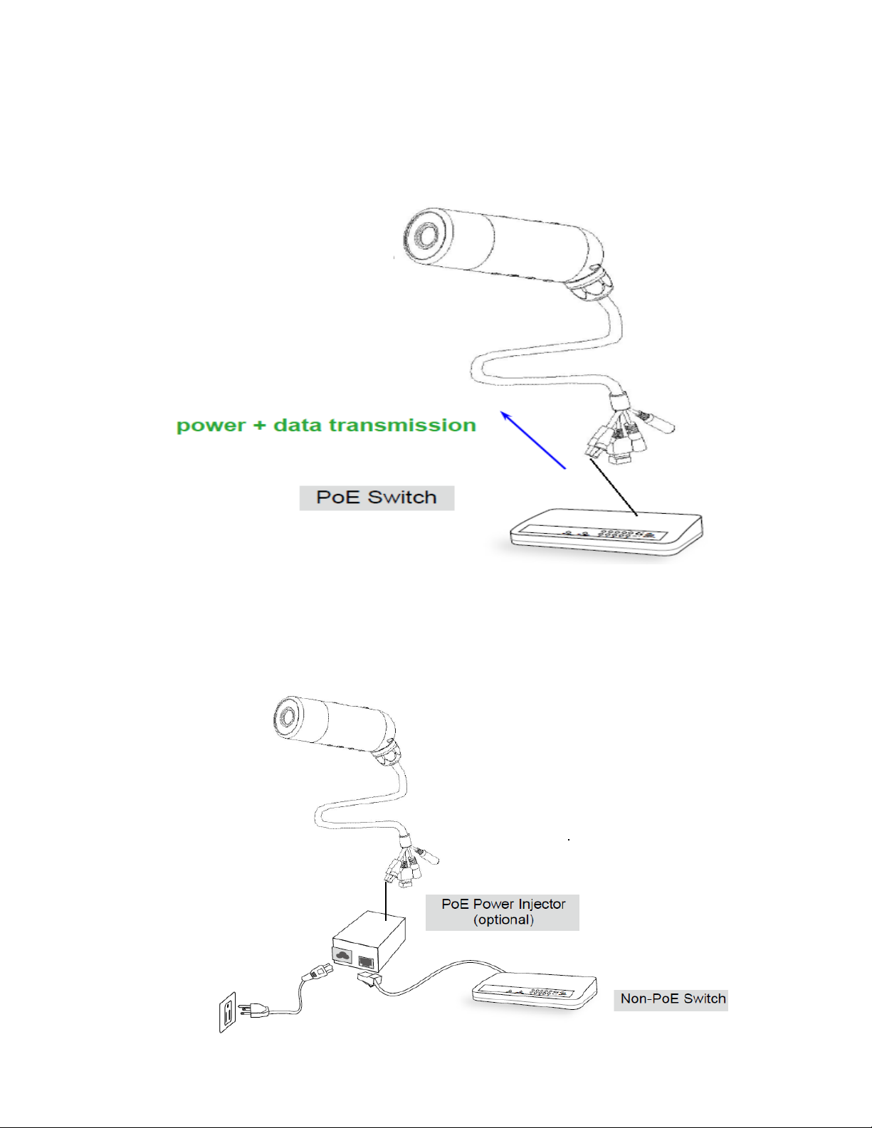
Set up the Network Camera through Power over Ethernet (PoE)
When using a PoE-enabled switch
The Network Camera is PoE-compliant, which allows it to be powered via a single Ethernet cable.if your switch/router supports PoE, refer to the
following illustration to connect the Network Camera to a PoE-enabled switch/router.
When using a non-PoE switch
If your switch/router does not support PoE, use a PoE power injector (optional) to connect between the Network Camera and a non-PoE
switch/router.
16
Camera setup installation & Usage
The camera Setup utility can easily and quickly detect cameras connected to your local network and list
them on the Camera Setup window, also you can use the camera Setup utility to assign an IP address to
each camera.
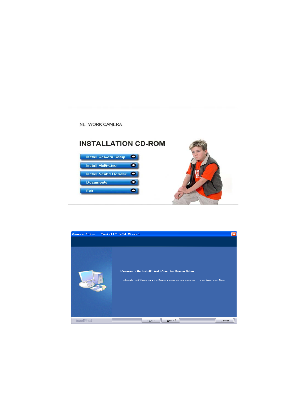
1. Insert the Installation CD into your CD-ROM drive and the installation screen should appear
automatically (See image below). If it does not, click “Start” then “Run”. In the text field enter
“D:\autorun.exe” (if “D:” is the letter of your CD-ROM Drive)
2. Click on “Install Camera Setup” and the following screen will be displayed.
3. If you want to change the default folder click “Change” to replace otherwise click “Next”
17
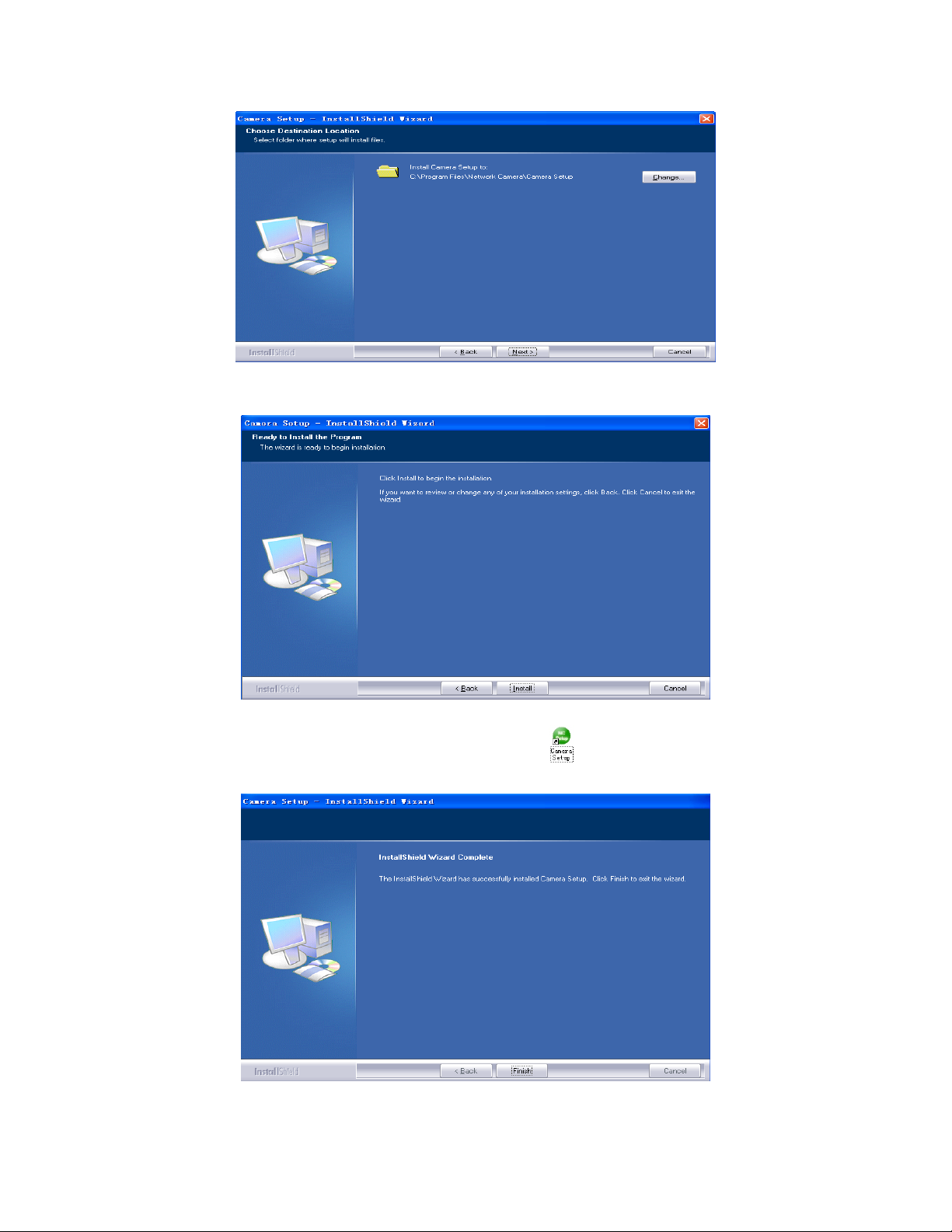
4. Click Install to install Camera Setup.
5. Click Finish to end the installation. You should now find a icon on the desktop.
18
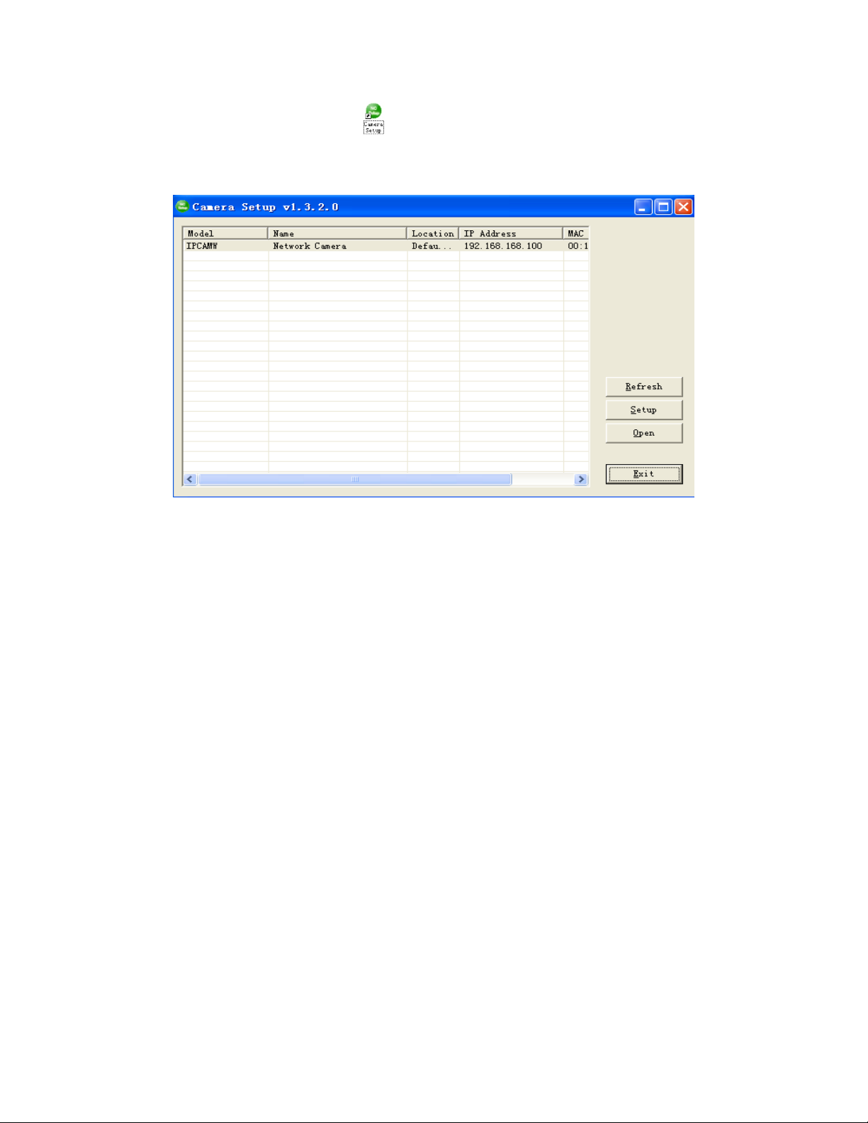
6. Doubl
utility should automatically find your camera if is correctly connected (See image below).
[Refresh] Click Refresh to search for cameras on the local network.
[Setup] Select the required camera and click Setup to configure the network settings for the camera.
[Open] Select the required camera and click Open to access the camera via a web browser.
[Exit] Click Exit to exit the Camera Setup window.
Note: Select and double click one of the cameras from the Device list, to open the camera view via the web
browser.
e-click the Camera Setup icon
on the Desktop to launch the program. The Camera Setup
19
Assigning an IP address to the Camera with Camera Setup
1. Launch Camera Setup program to detect cameras on the local network.
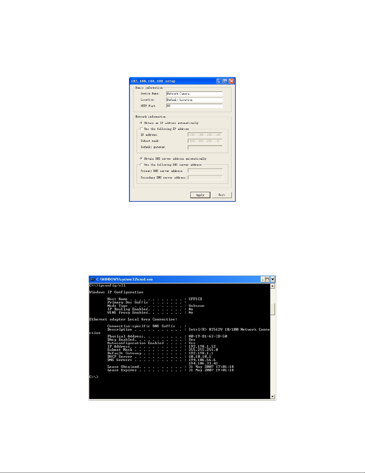
2. Click on “Setup” button and the following setup interface will pop up.
3. Enter a unique name for the camera, the location (optional) and leave the default port number as
80.“Obtain an IP address automatically” and “Obtain DNS server address automatically” are selected by
default, if you are confident enough to enter your own settings, you can do so by selecting “Use the following
IP address” and follow the guidelines on the next page. If however you wish to leave the default settings
please skip to NETWORK CAMERA SCREEN AND SETUP WINDOW.
4. To obtain the IP addresses specific to your network, click “Start” then “Run” and type “cmd” in the text box
and click “Ok”. The will bring up the MS-DOS prompt and in this window type “ipconfig/all” and press enter.
A screen similar to the one below will be displayed.
20

5.
Take note of
i) IP Address
ii) Subnet Mask
iii) Default Gateway
iv) DNS Servers (Both numbe
e secondary DNS server)
th
6. Enter the details noted in step 5 into the relevant fields.
Note: The default IP address of the camera is 192.168.168.100This can be changed to any IP address on
your IP range. For example if the IP address of your PC is 192.198.1.52 then the IP address of your cam
should be unique and on the same subnet, i.e. 192.198.1.X where X is any number between 1 an d 255
except 52. Ensure the IP address you chose is not the same as other network devic
th
is will result in conflict and may cause the device to not to work properly.
7. Once you’ve entered all the details click “Apply” then “Exit”.
the following:
rs with the first being the primary DNS server and the second being
era
es on your network as
21
Network Camera Screen and Setup Window
Review Images from the Network Camera
You can select one of the three ways to review pictures from the camera.
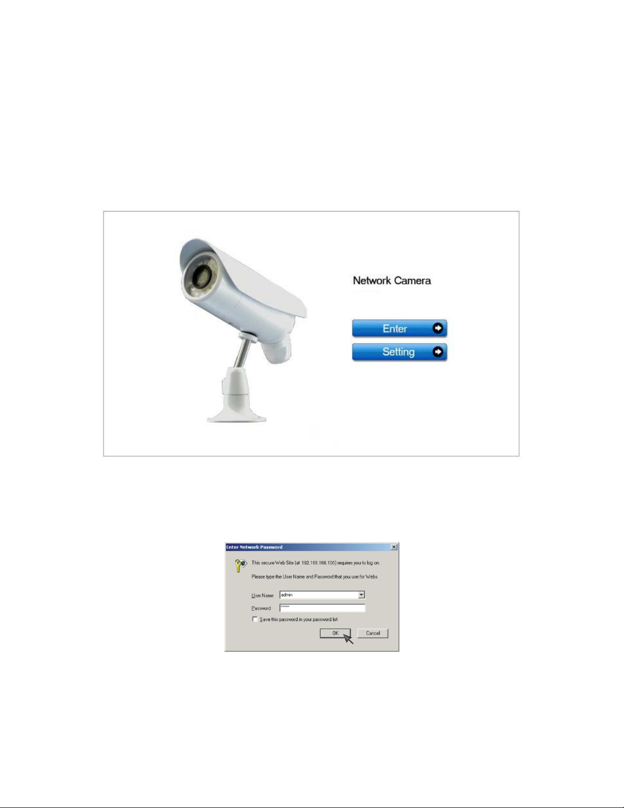
1. Input the assigned IP address (or URL) of the camera on the Web Browser. Take 192.168. 168.100 as
example. You will see the home page.
Notes:
Through this welcome page, you could choose to click on the item Enter to access the picture viewing
interface or the item Setting to access the system setting interface. The below dialog will appear. Input the
correct username (the default is admin, in lowercase) and password (the default is admin, in
lowercase). You are allowed to enter the picture viewing interface or the system setting interface.
The general users assigned by the administrator are not allowed to enter the system setting interface. They
can only be permitted to enter the picture viewing interface.
22
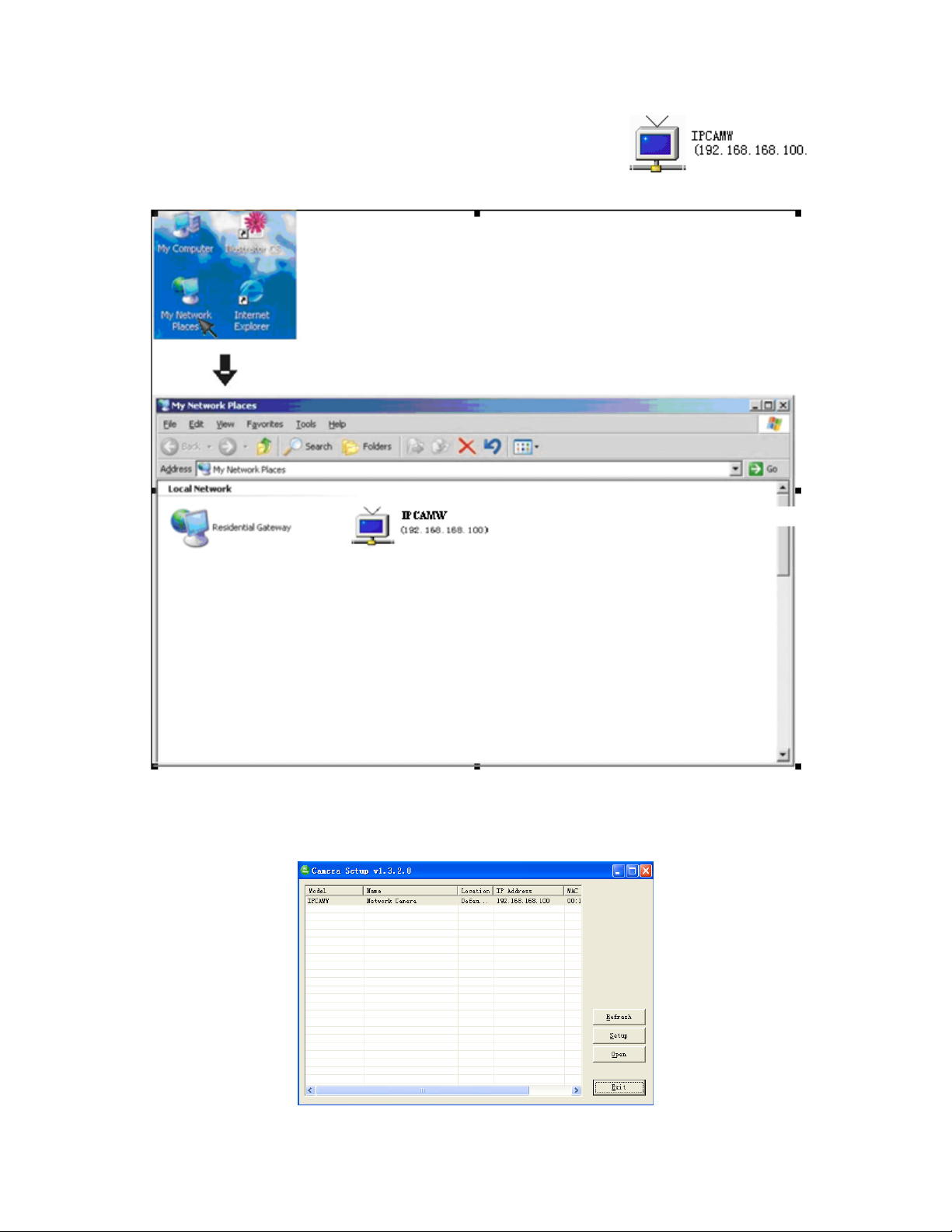
2. If your OS is Windows XP, click [My Network Places], double click the icon
You will see the home page.
3. Run the Camera Setup and double-click the relevant camera item.
23
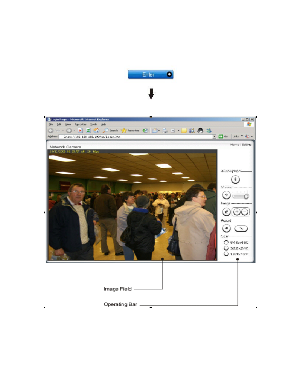
Operating Bar
Click Enter, you will see the screen.
24

[
Audio Upload] when you press this button
be talk.with.
,it can achieved two way audio function.two sides can
25

Viewing the camera from your mobile phone
The camera provides the ability to view the cameras monitored through your mobile phone as a live video
stream, it supports the telecommunications standard of 3GPP streaming format. All 3G enabled mobile
devices and most 2G phones that support the streaming standard of 3GPP are compatible. Otherwise, you
also can view the pictures even if your phone is not 3GPP compatible.
For example, if camera’s external IP address is 202.96.135.206 and external port is 8151, then type
http://202.96.135.206:8151/mobile in your Internet browser address bar of mobile phone, the login screen
will appear:
To click the “Picture live” button if your mobile phone is not 3GPP standard, then you can view the pictures
which will refresh every 3 seconds.
To click the “3GPP stream live” if your mobile phone support 3GPP standard, and the following screen will
appear:
Note: You have to click “Setting” button, make sure that the Mobile stream is enabled and the RTSP
authentication is disabled before you view the 3GPP stream live.
26

Network Camera Setting Interface
1. Click on settings from the home page. When connecting the camera for the first time or after resetting it
to its default settings, the setup interface start page below will load. It is recommend that you change the
admin password in order to avoid unauthorized access to the camera. To do this follow the instructions by
clicking on the underlined link “here” to access administrator password editing page.
2. Type the password in both fields then click Save. Please take note of the password. If you forget the
password, the camera will have to be reset to its default settings in order to gain access to the settings page
and this will also reset all other settings you may have changed.
27

3. You are required to re-login with the changed password.
After successful login, the following page will appear.
28

Camera
Camera Setup
From the home page click settings and enter the administrator user name and password. Click on Camera
Setup under the title Camera to change the image and audio parameters of the camera.
[Moonlight mode] Adjust the brightness setting according to the light intensity of the area being monitored
manually.
[Image rotation] Display images upside down.
[Light frequency] Two options: 50Hz & 60Hz. Set according to the mains frequency in the country of use.
For UK this would be 50Hz.
[Power LED light] Turn on/off the power & network LED indicator of camera.
[Show FPS in ActiveX]Show FPS On/Off in ActiveX control.
[Microphone] Turn on/off the built-in microphone.
[Mic volume] Adjusts the volume of the microphone from 0~14 where 0 is the lowest.
[Audio bit rate] Four options: 16, 24, 32, 40(kbps). Determines the quality of the audio being transmitted.
Click Apply to confirm your settings.
29

Stream Setup
The camera supports three streams: primary stream, secondary stream and mobile stream.
[Image size] Three image resolutions available: 640 x 480(VGA), 320 x 240(QVGA), 160 x 120.
[Frame rate] Twelve options: 1/2/3/4/5/6/8/10/15/20/25/30 frames per second (fps).
[MPEG4 bit rate] Select MPEG4 bit rate.Eight options: 64, 128, 256, 512, 768, 1024, 1536, 2048 (kbps).
[MJPEG quality] Type MJPEG video quality. (20 – 100), 20 is low quality, 100 is high quality.
[Snapshot quality] Type snapshot quality. (20 – 100) , 20 is low quality, 100 is high quality.
The above five settings determine the image quality, however higher bit r ates require greater bandwidth.
Please select the appropriate settings according to your connection speed and network traffic. If you are
experiencing jerky video it may be necessary to decrease the bit rate.
[Audio] Enable or disable audio.
[RTSP authentication] Enable or disable RTSP authentication.
You can use Mobile phone to play the mobile stream from camera, but generally Mobile phone do not
support authentication, so we have to disable the RTSP authentication.
30

A stream list page
[Primary stream] can not be disabled.
A sample of primary stream list as below:
will be shown after clicking the stream name such as “Primary stream”.
You can use RealPlayer, VLC Player or QuickTime Player to play the live stream from camera in
Intranet or Internet.
[Secondary stream] Enable or disable secondary stream.
[Mobile stream] Enable or disable Mobile stream.
You can use mobile phone, Realplayer and QuickTime Player to play the live stream from camera.
The size of video is 176x144.
Click Apply to confirm your setting.
31

OSD Setup
This function can display system name, date and time, or use-defined on screen.
[OSD] Enable or disable OSD function.
[Transparent] Users can select whether change OSD to transparent or not.
[Display date and time] OSD is date and time of camera.
[Display system name] OSD is system name of camera.
[Display the text below] OSD is user-defined text.
[Display the text below with date and time] OSD is user-defined text with date and time of camera.
Click Apply to confirm your settings.
32

Night Vision Setup (IR-CUT)
Only IR IPCAM have infrared LED, which can be opened automatically when camera check dark
environment.
[Infrared LED control] When the environment is dark, the LED will be opened automatically due to a
photosensitive component. Users also can select open or close the infrared LED manually.
[Black and white mode] When the environment is dark, the moving images will be changed to Black and
White automatically. Users also can select whether change the images to black and white or color manually.
Click Apply to confirm your settings.
33

Network
Wireless Setup
The camera corresponds to the wireless system based on IEEE802.11b/g. Encryption establishes the
security to prevent unauthorized users to access the wireless data communication.
[SSID] Type the ID of the wireless network you want to connect to using up to 32 ASC Ⅱ characters or click
Search to search for available networks.
[Mode] Infrastructure mode and Adhoc mode
Adhoc Mode: Select Adhoc mode when the camera is directly connected to your computer.
Infrastructure Mode: Select Infrastructure mode when the camera is connected via an access point or
router.
34

When select Adhoc mode. See figure above.
[Security mode] WEP64bit or WEP 128bit
[Authentication] Select WEP authentication mode.
[WEP Key type] Select the WEP key type. Either in hexadecimal or ASC Ⅱ characters.
[WEP key Index] Specify up to 4 WEP keys.
[WEP Key] Type the password.
[R-type WEP Key] Re-confirm the password.
When select Infrastructure mode. See figure above.
[Security mode] Security mode is not only WEP64bit or WEP128bit but also WPA-PSK or WPA2-PSK.
[Encryption type] TKIP and AES.
[WPA key]Type 8-63 characters as password.
[Re-type WPA key] Re-confirm the password.
35

When click search ,see figure above.
[SSID] select the network name you searched .
[Mode] Infrastructure mode and Adhoc mode
[signal]It show out the strength of signal
[Encryption ] on and off.
Click Apply to save changes.
Click Test to test whether connection is successful.
Note: These settings have to match those of your access point or router. Please consult your access point
or router manual on how to verify or modify these settings.
TCP/IP Setup
The camera is set up to obtain the IP address automatically (DHCP) by default. Should you may wish to
assign the IP address manually, use the TCP/IP Setup page to enter the address details.
36

Obtain an IP address automatically(DHCP):
If your network supports a DHCP server (e.g. router) select this option to have the IP address is assigned
automatically.
If you select Obtain an IP address automatically you should select Obtain a DNS Server address
automatically.
Use the following IP address:
Select this option when a fixed IP is required.
[IP address] Type the IP address of your camera.
[Subnet mask] Type the subnet mask.
[Default gateway] Type the default gateway.
Obtain DNS Server address automatically:
If your network supports a DHCP server (e.g. router) select this option to have the DNS Server address is
assigned automatically.
Use the following DNS server address:
[Primary DNS IP address] Type the IP address of the primary DNS server.
[Secondary DNS IP address] Type the IP address of the secondary DNS server, if necessary.
[HTTP/RTSP port]
The default HTTP port number is 80, it is also be used as RTSP port.
[RTP port range] It is for UPnP port forwarding, 1 camera actually use 2 RTP ports, one for video, the other
for audio. (See UPnP setup)
[HTTP/RTSP Authentication method] Select Basic Authentication or Digest Access Authentication.
PPPoE Setup
The camera can be installed without a PC on the network. Some XDSL services use PPPoE
(Point-to-Point Protocol over Ethernet).
[PPPoE dial-up] Enable or disable PPPoE connection.
[Service name] Either an ISP name or a class of services that is configured on the PPPoE server. This field
may be left empty.
37

[User name] Type the user name.
[Password] Type the password.
[Re-type password] Re-confirm the password.
Click Apply to confirm your settings.
DDNS Setup
Dynamic DNS (DDNS) is simply a way of using a static hostname to connect to a dynamic IP address.
When connected to your ISP, you are assigned a temporary IP address. DDNS services keep track of your
IP address and route your Domain name to that address when you wish to connect to the camera from a
remote location.
[DDNS] Enable or disable DDNS connection.
How to add DDNS
1. Enable the Dynamic DNS function.
2. Select your preferred DDNS service provider from the list then click Register.
3. Enter the Host Name details and password supplied by your DDNS service provider when you registered.
4. Click Apply to confirm your settings.
e.g.
38

39

UPNP Setup
The camera supports UPnP which is enabled by default. This function requires a Windows XP/Vista
operating system. It is a quick way to discover the camera on your network. Please make sure that the
UPnP function is enabled on your PC.
[UPnP] Enable or disable the UPnP function.
[Gateway HTTP/RTSP port forwarding] Enable or disable this function.
[External HTTP/RTSP port range] Using this port, automatically adds a port forwarding rule to a router via
UPnP protocol. Please note that not all routers support this function. Refer to your router manual for further
details.
If set port range is 8150~8350, camera will ask router to add a port forwarding rule automatically. In this rule,
the internal port is camera default port 80, the external port is 8150, IP address is camera's IP. Use this
setting, users can visit the camera from Internet through the router with this URL http://routeripaddress:8150
If there are several cameras in Local Network, the first one which first be opened will use 8150 as external
port, and second one will use 8151, third one use 8152, etc. Every camera will remember its port, it will
preferentially use this port in next power on.
[Gateway RTP port forwarding] Enable this function, users can use mobile phone , RealPlayer or
QuickTime Player to visit the camera from Internet through the router.
[External RTP port range] 30000—30200 default. (See TCP/IP setup)
Click Apply to confirm your setting.
Click System at the top right of Settings page to show the System information. See figure below.
.
40

41

If DDNS setup successfully and go into effect, Internet URL will show DDNS host name instead.
See figure below for example.
42

Alarm
Digital I/O Setup
[Digital input] Enable or disable digital input .
[Digital input’s active state is] Select the input’s active state.
[Digital output] Enable or disable digital output .
[Digital output’s active state is] Select the output’s active state .
Motion Detection
Motion Detection can trigger an alarm that sends images or video feed via e-mail or FTP (File Transfer
Protocol). You can set up to four different Motion Detection windows.
43

[Window] Check this box to enable the window.
[Threshold] Set the threshold bar to the amount of motion required to trigger the alarm.
[Sensitivity] Set the measurable difference between two sequential images that would indicate motion.
Click Apply to confirm your setting.
44

Schedule Setup
Alarm Sending, Periodical Sending and Buffer Sending sends images via e-mail or FTP according to
schedule setup.
[Every day] Select every day or not.
[Sunday ~ Saturday] Select Sunday ~ Saturday or not.
[Always] Enable in any time.
[Range] Enable between start time and end time.
[Except] Enable except start time to end time.
Click Apply to confirm your setting.
45

Alarm Management
Motion Detection can trigger an alarm that sends images via FTP or e-mail and send URL via HTTP.
[Alarm mode] Enable or disable all alarm.
[FTP alarm sending] Enable or disable FTP alarm sending function.
[e-Mail alarm sending] Enable or disable e-Mail alarm sending function.
[HTTP event alarm sending] Enable or disable HTTP event alarm function.
[Trigger time] How many seconds does camera keep snapshot the images after get a motion alarm.
[Trigger FPS] How many images does camera snapshot every second after get a motion alarm.
[FTP server ID] Select one FTP server, click Setting to set FTP server.
[Remote path] Path where to save the image file on the FTP server.
[Snapshot from] Select source stream that snapshot from.
[Image file name] Type image file name.
[Suffix of file name] Select suffix of file name.
[Effective period] Select Effective period. If select schedule, click Setting to set schedule.
46

[Trigger time] How many seconds does camera keep snapshot the images after get a motion alarm.
[Trigger FPS] How many images does camera snapshot every second after get a motion alarm.
[e-Mail server ID] Select one e-Mail server, click Setting to set e-Mail server.
[File attachment] Switch file attachment on or off.
[Snapshot from] Select source stream that snapshot from.
[Image file name] Type image file name.
[Suffix of file name] Select suffix of file name.
[Effective period] Select Effective period. If select schedule, click Setting to set schedule.
[HTTP server ID] Select HTTP server ID, click Setting to set HTTP server.
[Sending URL] Type URL which will be sent to HTTP server.
[Use MAC address as URL suffix] Enable or disable this function.
[Effective period] Select effective period. If select schedule, click Setting to set schedule.
Click Apply to confirm your setting.
47

Periodic Sending
The camera can send images via FTP or e-mail and send URL via HTTP periodically.
[FTP periodic sending] Enable or disable FTP upload periodically.
[e-Mail periodic sending] Enable or disable e-Mail upload periodically.
[HTTP periodic sending] Enable or disable HTTP upload periodically.
[Interval time] Type the interval at which you want to send the images periodically.
[FTP server ID] Select one FTP server, click Setting to set FTP server.
[Remote path] Path where to save the image file on the FTP server.
[Snapshot from] Select stream that snapshot from.
[Image file name] Type image file name.
[Suffix of file name] Select suffix of file name.
[Effective period] Select Effective period. If select schedule, click Setting to set schedule.
48

[Interval time] Type the interval at which you want to send the images periodically.
[e-Mail server ID] Select one e-Mail server, click Setting to set e-Mail server.
[File attachment] switch file attachment on or off.
[Snapshot from] Select stream that snapshot from.
[Image file name] Type image file name.
[Suffix of file name] Select suffix of file name.
[Effective period] Select Effective period. If select schedule, click Setting to set schedule.
[Interval time] Type the interval at which you want to send the URL periodically.
[HTTP server ID] Select HTTP server ID, click Setting to set HTTP server.
[Sending URL] Type URL which can be sent to HTTP server..
[Use MAC address as URL suffix] Enable or disable this function.
[Effective period] Set Effective period. If select schedule, click Setting to set schedule.
Click Apply to confirm your setting.
Note:
The notifications use the camera’s internal clock. Please make sure the camera’s Date and Time are
correct.
49

Buffer Management
The camera can be configured to send images via FTP when the Motion Detection alarm is triggered.
Note: This function just can be used when SD card does not plug in the SD slot of cameras.
[Image buffer] Enable or disable this function. Click Browse to preview images.
[Buffer time] Type buffer time.
[Buffer FPS] Type buffer FPS.
[Snapshot from] Select stream that snapshot from.
[Image file name] Type image file name.
[Suffix of file name] Select suffix of file name.
[FTP automatic sending] Enable or disable this function.
[FTP server ID] Select one FTP server, click Setting to set FTP server.
[Remote path] Path where to save the image file on the FTP server.
[Estimate sending time] Type estimate time that all buffer images send completed.
[Effective period] Select Effective period. If select schedule, click Setting to set schedule.
Click Apply to confirm your setting.
50

Alarm Server
FTP Server
[FTP server ID] Select FTP server ID.
[FTP server name] Type the name or IP address of the FTP server.
[FTP server port] The default port number is 21.
[Anonymous] Enable or disable anonymous login.
[User name] Type your user name.
[Password] Type your password.
[Re-type password] Re-type your password.
[Passive mode] Switch passive mode on or off.
[Keep alive] Type the time which keep alive with FTP server.
Click Apply to confirm your settings.
51

e-Mail Server
[e-Mail server ID] Select e-Mail server ID.
[SMTP server name] Type the name or IP address of the SMTP server you want to use for sending the
e-Mails. Please note that networks do not allow e-mail relaying. Check with your system administrator for
more details.
[SMTP server port] The default value is 25.
[Secure SSL connection] Select whether use SSL connection.
[Authentication] Select the authentication required by the SMTP server.
[User name] & [Password] Type the user name and password of the e-Mail account you wish to use.
This field is required if your SMTP server requires authentication.
[Re-type password] Re-type the password.
[Sender e-mail address] Type the e-mail address of the account you are using to send the e-Mail.
[Receiver e-mail address] Type the recipients’ e-mail addresses (Up to 3 address can be entered).
[Subject] Subject of the e-mail, entering a relevant subject will help identify the alarm better.
[Message] Type the text you wish to appear in the e-mail.
Click Apply to confirm your settings.
52

HTTP Server
[HTTP server ID] Select HTTP server ID.
[HTTP server name] Type the HTTP server name.
[HTTP server port] Type the HTTP server port.
[Authentication] Select the authentication required by the HTTP server.
[User name] Type the user name.
[Password] Type the password.
[Re-type password] Re-confirm the password.
Click Apply to confirm your settings.
53

SD Functions
Record on Alarm
[Alarm mode] Enable or disable all alarm.
[Record on alarm] Enable or disable alarm recording function.
Click Apply to confirm your settings.
54

[Recordr time] how many seconds does camera keep recording after a motion alarm.
[Record from] Select source stream that record from.
[Record file name] Type record file name.
[Suffix of file name] Select suffix of file name.
[Split time of record file ] How many seconds does every recording file save video and audio.
[Effective period] Select Effective period. If select schedule, click Setting to set schedule
55

Snapshot on Alarm
[Alarm mode] Enable or disable all alarm.
[Snapshot on alarm] Enable or disable alarm snapshot function.
Click Apply to confirm your settings.
[Trigger time] How many seconds does camera keep snapshot the images after get a motion alarm.
[Trigger FPS] How many images does camera snapshot every second after get a motion alarm.
[Snapshot from] Select source stream that snapshot from.
[Image file name] Type image file name.
[Suffix of file name] Select suffix of file name.
[Effective period] Select Effective period. If select schedule, click Setting to set schedule.
Click Apply to confirm your settings.
56

Continuous Record
[continuous record] Enable or disable continuous recording function.
Click Apply to confirm your settings.
[Record from] Select source stream that record from.
[Record file name] Type record file name.
[Suffix of file name] Select suffix of file name.
[Split time of record file ] How many seconds does every recording file save video and audio.
[Record period time] Select record period time. If select schedule, click Setting to set schedule.
Click Apply to confirm your settings.
57

Snapshot at Interval
[Snapshot at interval] enable or disable interval snapshot function
[Interval time] Type the interval at which you want to save snapshot to SD card periodically.
[Snapshot from] Select stream that snapshot from.
[Image file name] Type image file name.
[Suffix of file name] Select suffix of file name.
[Effective period] Select Effective period. If select schedule, click Setting to set schedule.
Click Apply to confirm your settings.
58

SD FTP Sending
This function is used for sending the files of SD card to FTP server.
Notice: when users visit the video, uploading will automatically interrupt, and will restart when users stop visit
the video.
[SD File FTP Sending] enable or disable SD FTP sending function
[FTP server ID] Select one FTP server, click Setting to set FTP server.
[Remote path] Path where to save the file on the FTP server.
[Sending period] Select sending period. If select schedule, click Setting to set schedule.
[File period] Select the files which creation time is in period to sending. If select schedule, click Setting to set
schedule.
[FTP upload bandwidth] Evaluate the uploading speed of FTP sending files.
Click Apply to confirm your settings.
59

Browse SD Card
When click Browse and see figure below,you can browse, download, delete the snapshot and recording files in
it,
60

Format SD Card
To format SD card, all files will be losted after format.
61

Tools
System Identity
[System Name] Type a name to easily identify the camera.
[System Contact] Type the contact name of the administrator of the camera.
[System Location] Type the location of the camera.
TIP: The information you fill in can be displayed on the camera. It can help to distinguis h different Network
Cameras in the network. See figure below.
62

User Management
[Add] Up to 64 users (including the admin) can created
Note:
1. A maximum of 16 users are allowed to access the camera simultaneously.
2. As the number of simultaneously users increase, the overall performance will decrease. This is dependant on
the Network bandwidth.
Adding users
1. Click Add on the Camera User List page.
2. Enter the User name, Password and re-confirm the password then click Add.
To edit a user’s password, click on the user name then enter the new password for that user twice and click
Save. To delete a user, click on the user name then click Delete.
63

Date & Time
[Current device time] Internal time for camera.
[Proposed device time] PC system time. On clicking Apply the internal time of the camera will be changed to
this time.
[Select to change the time zone for the device location] choose proper time zone.
[Daylight saving time]Daylight Saving Time (or summertime as it is called in many countries) is a way of getting
more light out of the day by advancing clocks by one hour during the summer.
[Date and time format] Select date and time format.
[Auto time setting(SNTP)] Enable or disable this function.
[Time server] Type one SNTP server name in the box.
Click Apply to confirm your settings.
Note:
1. If the SNTP server is not found the camera’s time will be synchronized with the PC time.
2. The camera has a built-in RTC(Real-time Clock) that keeps track of the time even when power is
disconnected.
64

Backup or Reset
[Reset] Click Reset to initialize the camera to default factory setting. All users and settings will be
lost, requiring you to reconfigure the camera.
[Backup] Click Backup to backup the current configuration of the camera for future reference.
[Browse...] Click Browse... to search for a backup configuration you wish to upload to the camera, then
click Restore.
Note:
Do not turn off the power during the Reset, Backup or Restore functions since this might corrupt the
camera’s firmware
Tip:
The camera can also be reset to the default settings by pressing the reset switch on the side of the camera.
65

Firmware Upgrade
From time to time a new firmware may be released. In order to upgrade your camera’s firmware you first
need to download this firmware from Network Camera Technical Support Site.
1. Click Continue.
2. Click Browse... to search for the newest Firmware you downloaded, and then click Upgrade.
3. Click Reboot when the upgrade terminates.
IMPORTANT:
* Do not unplug or power off the camera while the u pgrade is in progress.
66

SPEEDREAD YOUR NETWORK CAMERA
Wizard
In order to facilitate the setup of the camera there is a Wizard that helps non technical users setup the
camera easily. Click on Wizard at the top of the window to launch the wizard.
The Quick setup interface will pop up. Follow the simple instructions on the screen and enter the required
details, clicking next to proceed to the Next page.
67

System
Click System to see over system information about your camera. The data of the software activity of the
camera and recorded in this. It includes data that are useful when a problem occurs.
Support
Click Support to see the support information
Reboot
Click Reboot to restart the camera. Rebooting the camera will retain all the settings and configurations.
68

ADVANCED SETTINGS
Port Forwarding
The UPnP Setup of camera show a method of Port Forwarding(see page 40 for details),but some routers
maybe can’t support UPnP Port Forwarding, therefore, users need to
Firewall security features built into the router may prevent users from accessing the camera over the Internet.
The router connects to the Internet over a series of “ports”. The default ports used by the camera are usually
blocked from access over the Internet, therefore, these ports need to be made accessible. This is achieved
using the Port Forwarding function on the router. The ports used by the camera must be opened through the
router for remote access to your camera. Check your router’s user manual for specific instructions on how to
open and route ports on you router.
Important: Some ISPs block access to port 80 and other commonly used Internet ports. Check with your
ISP in order to open the appropriate ports. If your ISP does not pass traffic on port 80, you will need to
change the camera’s default port number from 80 to a different number such as 9000.
Viewing Your Camera
To access the camera from a computer on your local network, simply enter the IP Address of the Camera
followed by a colon and the camera’s port number. It is not necessary to enter the colon and port number if
you are using the camera’s default port 80.
To access the camera from the internet, type the external IP Address of the router, followed by a colon, and
the port number of your camera (e.g., Http://210.118.166.68:9000).
configure Port Forwarding manually.
69

Proxy Server Setting
A proxy server may prevent you from connecting to the camera in some corporate environments. The web
browser can set up the IP address communication without using a proxy server. Consult your ISP or network
administrator for further details.
Note: A proxy server is generally used to maintain security on a network when connected to the internet.
The proxy server may cause lack of image quality and delays in refresh intervals. Consult your ISP or
network administrator for further details.
1. Start Internet Explorer.
2. Select [Tools] –> [Internet Options...] –> [Connections] tab and click [LAN Settings].
Verify that the Use a proxy server check box is not checked. When checked, click [Advanced...].
When not checked, click [Cancel]. Your proxy server settings should not cause any problems.
3. Enter the IP address of your camera into the Do not use proxy server for addresses beginning
with data field.
4. Click [OK] on all of the opened windows.
70

Reset the camera
There are two ways to reset the camera back to its factory defaults:
1. Press the Reset button on the side of the camera through the pin hole.
2. Through the camera setup under the heading Backup or Reset (see page 65 for details)
71

DEFAULT SETTINGS
Privacy mode Off
Moonlight mode Off
Image rotation Off
Light frequency 60Hz
Microphone Enable
Mic Volume 10
Audio Bit Rate G. 726 (16kbps)
Primary stream Enable
Image size 640 x 480
Frame rate 30fps
MPEG4 bit rate 2048kbps
MJPEG quality 50
Snapshot quality 90
Audio Enable
RTSP authentication Enable
Secondary stream Disable
Image size 320 x 240
Frame rate 30fps
MPEG4 bit rate 512kbps
MJPEG quality 50
Snapshot quality 90
Audio Enable
RTSP authentication Enable
Mobile stream Enable
Image size 176 x 144
Frame rate 10fps
MPEG4 bit rate 64kbps
Snapshot quality 70
Audio Disable
RTSP authentication Enable
OSD Disable
Transparent Enable
Display Display date and time
Infrared LED control Auto
Black and white mode Auto
SSID Wirelessnc
Mode Adhoc
Security mode Off
IP address 192.168.168.100
Camera
Camera Setup
Stream Setup
OSD Setup
Night Vision Setup
Network
Wireless Setup
TCP/IP Setup
72

Subnet Mask 255.255.255.0
Default Gateway Blank
Primary DNS IP Address Blank
Secondary DNS IP Address Blank
HTTP Port 80
RTSP port 554
RTP port range 30000—30200
Authentication method Basic
PPPoE Setup
PPPoE Dial-up Disable
Service Name Blank
User Name Blank
Password Blank
Re-type Password Blank
DDNS Setup
DNS Disable
Service provider dtdns.com
Host name Blank
User name Blank
Password Blank
Re-type password Blank
UPnP Setup
UPnP Enable
Gateway HTTP/RTSP port
forwarding
External HTTP/RTSP port
range
Gateway RTP port forwarding Enable
External RTP port range 30000--30200
Enable
8150--8350
Alarm
Motion Detection
Window 1 Blank
Window 2 Blank
Window 3 Blank
Window 4 Blank
Schedule Setup
Every day Always
Alarm Sending
Alarm mode Arm
FTP alarm sending Disable
Trigger time 5
Trigger FPS 1
FTP server ID 1
Remote path Blank
Snapshot from Primary stream
Image file name M
Suffix of file name Date time
Effective period Always
e-Mail alarm sending Disable
Trigger time 1
Trigger FPS 1
e-Mail server ID 1
File attachment On
73

Snapshot from Primary stream
Image file name M
Suffix of file name Date time
Effective period Always
HTTP event alarm sending Disable
HTTP server ID 1
Sending URL Blank
Use MAC address as URL
suffix
Effective period Always
Periodical Sending
FTP periodical sending Disable
Interval time 0H 1M 0S 0mS
FTP server ID 1
Remote path Blank
Snapshot from Primary stream
Image file name P
Suffix of file name Date time
Effective period Always
e-Mail periodical sending Disable
Interval time 0H 1M 0S 0mS
e-Mail server ID 1
File attachment On
Snapshot from Primary stream
Image file name P
Suffix of file name Date time
Effective period Always
HTTP periodical sending Disable
Interval time 0H 1M 0S 0mS
HTTP server ID 1
Sending URL Blank
Use MAC address as URL
suffix
Effective period Always
Buffer Sending
Image buffer Disable
Buffer time 20
Buffer FPS 4
Snapshot from Primary stream
Image file name Blank
Suffix of file name Date time
FTP buffer sending Disable
FTP server ID 1
Remote path Blank
Estimate sending time 100
Effective period Always
Disable
Disable
Alarm Server
FTP Server
FTP server ID 1
FTP Server Name Blank
74

FTP Server Port 21
Anonymous No
User Name Blank
Password Blank
Re-type Password Blank
Passive Mode On
Keep alive 3600
e-Mail Server
e-Mail server ID 1
SMTP Server Name Blank
SMTP Server Port 25
Secure SSL connection No
Authentication Yes
User Name Blank
Password Blank
Re-type Password Blank
Sender E-Mail Address Blank
Blank
Receiver E-Mail Address
Subject Warning from Network
Message Blank
HTTP Server
HTTP server ID 1
HTTP server name Blank
HTTP server port 80
Authorization No
User Name Blank
Password Blank
Re-type Password Blank
Blank
Blank
Camera
Tools
System Identity
System Name Network Camera
System Contact Default Contact
System Location Default Location
User Management
1 Admin/Administrators
Date & Time
Current Device Time Current PC Time
Time Zone GMT
Proposed Device Time Current PC Time
Daylight saving time Disable
Date and time format dd/mm/yy hh:mm:ss
Auto Time Setting (SNTP) Enable
Time Server Time.nist.gov
Misc Setup
LED Control On
Show FPS in Active Control Off
75

SPECIFICATIONS
Camera
Image device 1/4" CMOS
Pixels 310000
White Balance Auto
Exposure mode Auto
Gain Auto
Viewing angle Horizontal:50°, Vertical:40°
Focal length f=4.3mm
Aperture F2.0
Min.llumination 1.0 Lux
Infrared LED 12
Night Vision Distance 15m
IR cut filter Yes
Network
Image compression MPEG-4 MJPEG
Image resolution 640x480(VGA), 320x240(QVGA), 160x120(QQVGA)
Max. frame rate 30fps @640x480
Aduio compression AMR(4.75 -- 12.2Kbps), G.726 (40/32/24/16Kbps)
Simultaneous viewers 16
Authentication ID/Password, Administrator/General User (Up to 64)
Network protocols TCP,UDP,IP,ARP,ICMP,DHCP,DNS,HTTP,FTP,SMTP,NTP,PPPoE,UPnP,DDNS
Stream type RTSP/RTP/RTCP, 3GPP, ASF, HTTP
Network connection Ethernet (10BASE-T/100BASE-TX)
Wireless LAN
Wireless technology IEEE802.11b/g
Frequency 2.412-2.462GHz
Transmission speed 54Mbps/22Mbps/11Mbps/5.5Mbps/2Mbps/1Mbps (Auto Switch)
Security WEP (64/128 bit), WPA-PSK(AES/TKIP), WPA2-PSK(AES/TKIP)
External Port
Built-in microphone Electret Condenser Microphone
Audio output (2 way audio) Yes
SD slot Yes
Digital I/O 1 input, 1 output
General
Power requirements DC 12V
Power consumption 3.5W
Power over Ethernet (POE) Yes
Operating temperature -5 to +45 °C (+22 to +113 °F)
Storage temperature -20 to +60 °C (-4 to +140 °F)
Operating humidity
Storage humidity
20~80%RH(Non-condensing)
20~95%RH(Non-condensing)
76

Dimensions(W x D x H) 70mm x 70mm x 190mm
Weight 700g(Main Body)
Supplied accessories
PC system requirements
Operating system Windows 2000/XP/Vista
Processor Intel Pentium III, 1GHz or Higher
Memory 256MB RAM Minimum
Web browser Microsoft Internet Explorer Version 5.5 or Later
AC adaptor (x1), CD-ROM(x1 setup program and user manual), Stand(x1),
Sun shard(x1)
TROUBLESHOOTING
If the Network Camera is not working properly, these suggestions might help you identify the problem. If the
problem persists check the support pages on Network Camera Technical Support Site.
Problem Cause and Remedy
1. Use Camera Setup.
2. Use UPNP (for XP/Vista OS)
Forget the IP address of network camera.
3. PPPoE IP Notification can send e-mail to your
mailbox
4. Reset your Network to default IP address
Forget the password to access the
setting interface.
Wireless communication does not work.
The picture viewing interface does not
appear.
The color of the picture is strange. Confirm the color setting of PC is 16 bits or more.
The unreadable characters are displayed.
Initialize the network camera by pressing the
RESET button. Note that all configuration settings
will be lost.
1. Signal strength is weak. Relocate the camera or
remove the obstacle around it.
2. Make sure the SSID and Encryption settings are
identical.
3. Check for any interference from other equipment.
1. Check that your internet explorer settings allow
you to download and install ActiveX controls.
2. Maximum 16 users are allowed to access the
camera simultaneously through network.
3. Network traffic may prevent the viewing interface
from appearing quickly. Wait for a while.
Set the Encoding or the Character Set of the
selected language on the web browser.
77

GLOSSARY OF TERMS
1. Network Camera: A stand-alone device which allows users to view live, full motion video from anywhere
on a computer network, even over the Internet, using a standard web browser.
2. JPEG: A standard image format, used widely for photographs, also known as JPG.
3. IEEE 802.11b/g: The specifications developed by the IEEE for wireless network technology. It provides
11 Mbps transmission in the 2.4GHz band usage.
4. WEP: Wireless Equivalent Privacy. A security protocol for wireless network defined in the IEEE 802.11b/g
standard. WEP aims to provide security by encrypting data over radio waves so that it is protected as it is
transmitted from one end point to another.
5. Adhoc Mode: A wireless network system in which devices communicate directly with each other, without
the use of a wireless router.
6. Infrastructure Mode: One of the wireless network system in which devices communicate with each other
by first going through the wireless router.
7. IP Address: The unique 32 bit number assigned to each computer connected to the Internet. IP numbers
are used by the TCP/IP protocol to route packets of data to their destinations.
8. TCP/IP: The collection of "protocols" underlying the functioning of the Internet. Each computer connected
to the Internet is identified by a unique IP Address.
9. SMTP: Simple Mail Transfer Protocol.
10. FTP: File Transfer Protocol. Network cameras equipped with an embedded operating system, such as
Linux, can use FTP to send images to a website.
11. DHCP: Dynamic Host Configuration Protocol is a set of rules used by communications devices such as
a computer, router or network adapter to allow the device to request and obtain an IP address from a server
which has a list of addresses available for assignment.
12 UPnP: Universal Plug and Play is an architecture for pervasive peer-to-peer network connectivity of
intelligent appliances and wireless devices.
13. DDNS: DDNS is a method of keeping a domain name linked to a dynamic IP address with your Network
Camera. You can set up your DDNS service and the device will automatically update your DDNS server
each time it alter a different IP address.
14. Time server: A time server consists of a computer networking device that reads the actual time from a
reference clock and distributes this information to its clients using a computer network.
15. WPA:
computer networks. WPA implements the majority of the IEEE 802.11i standard, and was intended as an
intermediate measure to take the place of WEP while 802.11i was prepared.
Wi-Fi Protected Access (WPA and WPA2) is a class of systems to secure wireless (Wi-Fi)
78

79

FCC Caution
This device complies with part 15 of the FCC Rules. Operation is subject to the following two
conditions:
(1) This device may not cause harmful interference, and (2) this device must accept any
interference received, including interference that may cause undesired operation.
NOTE 1: This equipment has been tested and found to comply with the limits for a Class B digital
device, pursuant to part 15 of the FCC Rules. These limits are designed to provide reasonable
protection against harmful interference in a residential installation. This equipment generates, uses
and can radiate radio frequency energy and, if not installed and used in accordance with the
instructions, may cause harmful interference to radio communications. However, there is no
guarantee that interference will not occur in a particular installation. If this equipment does cause
harmful interference to radio or television reception, which can be determined by turning the
equipment off and on, the user is encouraged to try to correct the interference by one or more of
the following measures:
- Reorient or relocate the receiving antenna.
- Increase the separation between the equipment and receiver.
-Connect the equipment into an outlet on a circuit different from that to which the receiver is
connected.
-Consult the dealer or an experienced radio/TV technician for help.
NOTE 2: Any changes or modifications to this unit not expressly approved by the party
responsible for compliance could void the user's authority to operate the equipment.
 Loading...