

Growatt New Energy
Down lo ad
Manu al
Shenzhen Growatt New Energy Technology CO.,LTD
No.28 Guangming Road, Shiyan Street, Bao’an District,
No.28 Guangming Road, Shiyan Street, Bao’an District,
Shenzhen, P.R.China
Shenzhen, P.R.China
T
+86 0755 2951 5888 +86 0755 2951 5888
service@ginverter.comservice@ginverter.com
E
www.ginverter.comwww.ginverter.com
W
GR-UM-180 A-00-GR-UM-180 A-00-
Installation Manual of SPH series
Installation
Manual
&
SPH TL BL-UP series

Brief Introduction
1
Safety
2
list
1.1 Preface
1.2 Target G roup
1.3 Product De sc ri ption
1.4 Safe ty I nstructions
2.1 Purp os e Use
2.2 Safe ty M easure
2.3 Symb ol s introd uction on the
SPH inve rt er
Product Description
3
Unpacking
4
3.1 Growatt SP H se ri es inverter
3.2 Labe l Ex planation
3.3 Size a nd w eight
3.4 The ad va ntage of the unit of
Growatt SPH

Installation
5
Commissioning
6
5.1 Basi c in stallation requirements
5.2 Inst al lation requires tools and
RJ 45 term in al sequence of the
LAN line
5.3 Inst al lation Instruct io ns
5.4 Grounding co nn ection
SPH Syst em e lectrical Conne ct ion 5.5
6.1 Comm is sioning of SPH
6.2 Oper at ion modes
6.3 Coun tr y setting
6.4 Disp la y and button
6.5 Comm un ication
EU Declaration of
10
Conformity
Manufacturer
11
Warranty
Decommissioning
12
Product specification
13
12.1 Dis ma ntling the energy s to rage
12.2 Pac ki ng the SPH inverter
12.3 Sto ri ng SPH inverter
12.4 Dis po sing of the SPH inver te r
Start-up and shut
7
down SPH system
Attention of the
8
installation
environment,
maintenance and
cleaning
Fault removal
9
7.1 Star t- up the SPH system
7.2 Disc on nect the SPH system
14
15
13.1 Growatt SPH s er ies energy
storag e ma chine product
specif ic ation
13.2 DC in pu t terminal parame te r
13.3 Torque
13.4 App en dix
Certificate
Contact
1 Brief Introduction
1.1 Preface
This m anual w il l provide t he users wh o use t he Growatt SP H Serie s of GROWATT NEW
ENERGY TECHNOLOGY CO.LTD .S HE NZHEN(Short for Growatt New Ene rg y as be low)
with t he deta il ed product in formation a nd the in stallation instruction s. Please rea d
this m anual c areful ly and pu t this ma nual on some pla ce where is convenient to
instal la tion, ope ra tion, obt ai n. Any modifications of Growatt new ener gy, we will no t
notify the us er.
1.2 Target Group
Growatt S PH TL BL-UP inverter m us t be inst al led by profes si on al electri ca l personne l
who have obtaine d the cert if ication of the re le va nt de partments. We have two k inds
of energy storag e machin e for diff eren t batter y one i s for lithium battery and the
other is for lea d-acid battery, we suggest: customer should decide which kind of
energy storage machine you want, Growatt can provide onl y lithium battery with
energy s torage mach in e, customer c an change t o lead-acid m od e provide by Growatt
while they can buy t hese battery from market easily. Es pe cially if customer choose
energy storage sy st em with l ithium b at te ry (whic h must be prov id e by Growat t or in
the compatibility list which pro vi de b y Growatt) b ut u se d for lea d- acid b attery o r
used l ead-acid ba ttery f or lithium bat te ry model, it will b e dangerous. In staller c an
instal l e ne rgy storag e m ac hine of Growatt SP HT L B L-UP Series rap id ly and
troublesho ot in g, b ui ld c om munication system through re ad thi s manu al carefully. If
yo u hav e an y que sti ons i n th e proce ss of inst all ati on, you c an l ogi n in
www.growatt .c om
hotlin e :+ 86 0755-2951588 8.
and leav e som e message. Or you can ca ll ou r 24-hour service
1.3 Product Description
Growatt SPHTL BL-UP S eries is used to store energy generated by th e p ho tovoltaic
cell pa nels or e ne rgy from grid if it i s allowed i n the bat te ry, also energy can be sent
to p ower gr id through SP H TL BL-UP f or self consumption or wh en Grid power is lost,
SPH TL BL- UP c an be used as back up pow er.
SPH seri es h as six kinds of type:
•Growatt SPH3 00 0 TL B L-UP
•Growatt
•Growatt SPH4 00 0 TL B L-UP
•Growatt SPH4 60 0 TL B L-UP
•Growatt SPH5 00 0 TL B L-UP
•Growatt SPH5 60 0 TL B L-UP
Note: we d es cribe this series a s “S PH” as below.
Note: In different coun tr y,we prov id e different pow er.Such as in Germany,w e can
provide SPH3 00 0~ SPH4600,but w e do n’t provid e SP H5000 and SPH6000 .
1
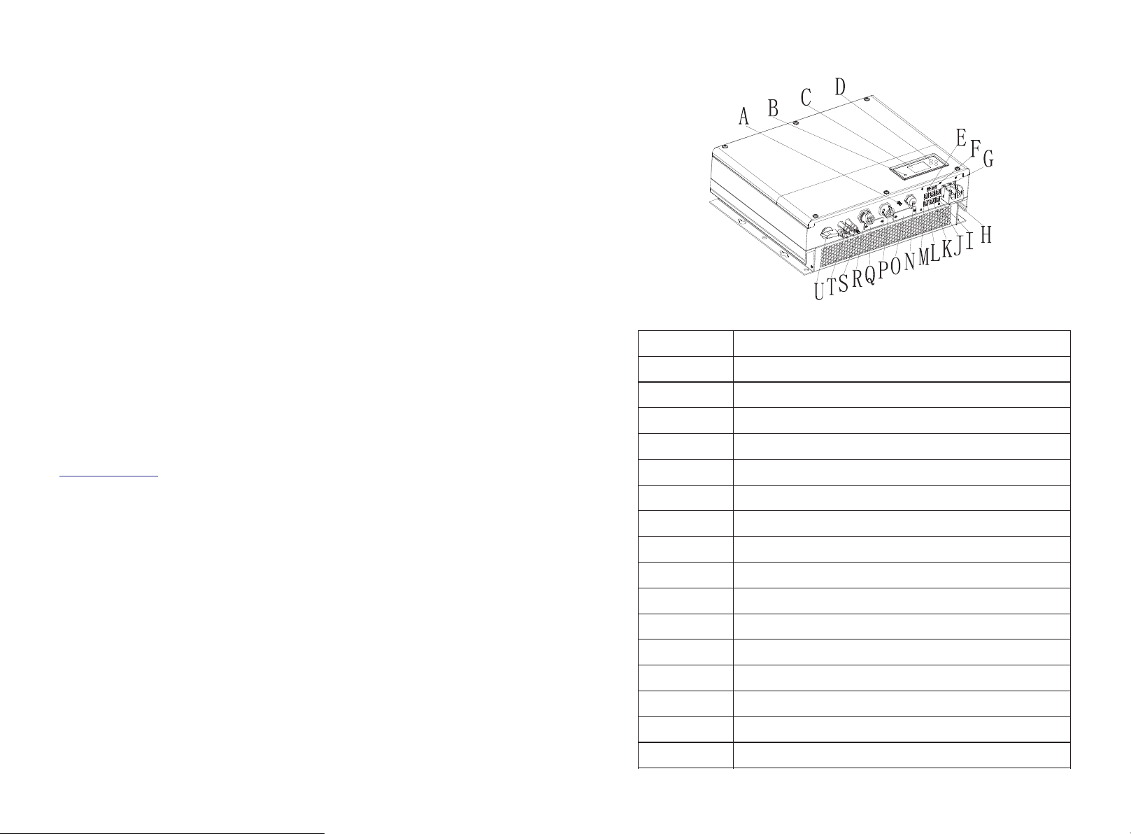
SPH360 0 TL B L-UP
Overview:
Positi on
A
B
C
D
E
F
G
H
I
J
K
L
M
N
O
P
Chart 1. 1
Descri pt ion
Antenn a
LED of sta tu s display
LCD screen
Functi on b utton
DIP swit ch(s et safety standard)
Dry cont ac t
RS 485 com mu nication interf ac e of Lithium batt er y
Batter y te rminal
CAN comm un ication interfa ce o f Lithium batte ry
RJ45 int er face of DRMs(used o nl y in Australia)
NTC: Lea d- acid temperature sens or t erminal
RS 485 com mu nication interf ac e of meter
CT input t er minal
USB inte rf ace
RS 232/W i-Fi/sh in el ink cover board
AC Grid (o n gr id connection)
2
2.1 Purpose Use
Positi on
Descri pt ion
Q
RSD(do n ot o pen except by Professio na l staff)
R
UPS outp ut
S
Ground point
T
PV input
U
PV switc h
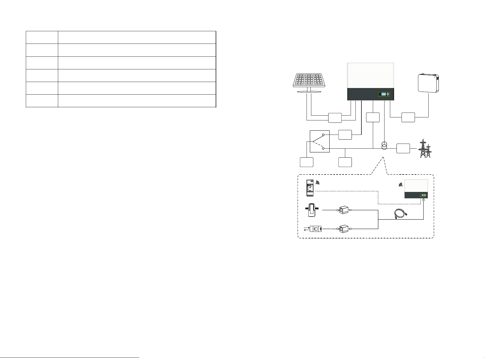
The syst em c hart of SPH:
Safety 2
Hyb rid Inv erter
1.4 Safety Instructions
1.Plea se be clear which k in d of ba ttery s ys tem you want, lithium b attery sy st em or
lead-a ci d battery system, i f yo u choose the wrong system , SP H can't work norm al ly.
2.Plea se read t hi s manual carefully b ef ore the i nstallation , the c om pany ha s the r ight
not to qu ality as surance, if no t ac co rdin g to the instructions of this manual fo r
instal la tion and cause equi pm ent damage.
3.All the operat io n a nd co nn ection please professiona l e le ctrical or mec hanical
engine er.
4.Duri ng i nstallation, pl ea se don’t touch the other pa rt s within the box.
5.All th e el ectrical instal la tion must compl y wi th the local electr ic al safety stand ards.
6.If equipments needs t o maintain , please co ntact wi th local specify sy stem
instal la tion and maintena nc e personnel.
7.Use t he equip me nt to combined t o grid nee ds to obtain the per mi ssion of loc al
power su pp ly department.
PV Arr ay
TSS P(Opt ional )
UPS
Loa d
DC
Bre aker
AC
Bre aker
Loa d
UPS Gri d
Bre aker
Sen sor
DC
Bre aker
AC
Bre aker
Bat tery
Ele ctric al Grid
1
Rai lLog
L line
2
L,N
3
L,N
5m
CT
5m
Ele ctic me ter
Chart 2. 1
As shown above, a complete gri d- connected system of SPH consist s of PV modules,
SPH inve rt er, battery, utility grid an d ot her components.
30m
10m
8.When i nstall PV m od ul es in the d ay time, ple as e turn off th e PV switch , ot herwise it
will be da ng erou s as h igh terminal vo lt age of modules in the s un shine.
3
Attent io n:
Batter y in stallation requirement
As the system refer to bat tery use, we must make sure ventilatio n of the servic e
environmen t an d te mp erature co ntro l in o rder to prevent the dang er o f ba tt ery
explos io n, batter y re commended i nstallation environment must be strictly in
accordance with the speci fi cation, if the specificati on is IP20 environment, the
pollut io n degre e of the unit i s P D2, meanwhil e t he temperature shou ld be control in
the 0-40℃ of indoor ventilation and the hum id ity s ho ul d be 5%-85%. If the chosen
PV modules nee ds to positive or n egative ground con ne ction, ple as e contact with
Growatt for te ch ni cal support bef ore inst al lation.
4
2.2 Safety Measure
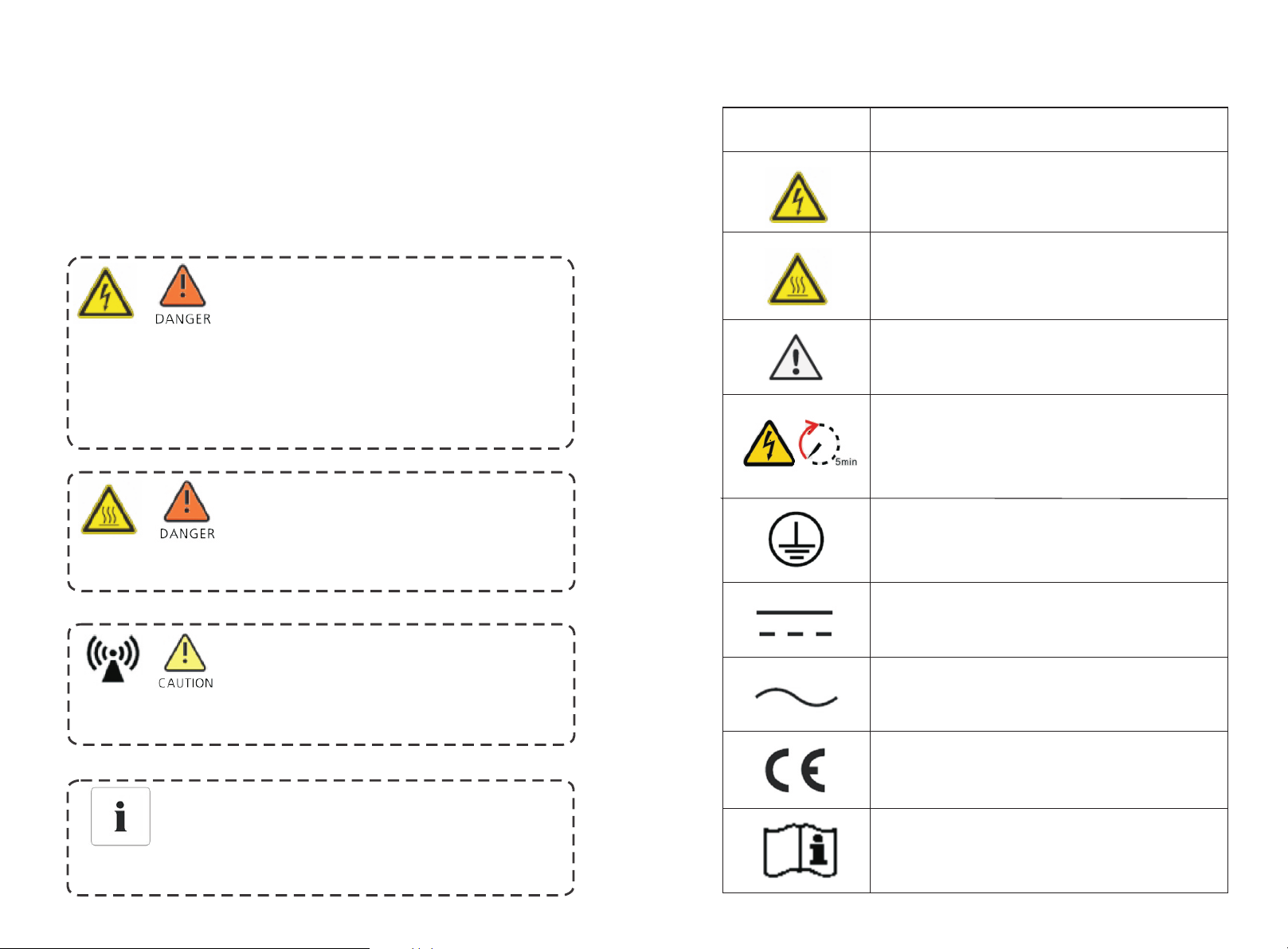
2.3 Symbols introduction on the SPH inverter
PV modul es C apacitive Disch ar ge Currents
PV modul es w ith large capacit ie s re la tive to earth, such a s th in-film PV modu le s wi th
cells on a m et allic substrate , ma y only be used if the ir c oupling capacit y do es not
exceed 4 70 nF. During feed-i n op eration, a leak ag e curren t flows from the cells to
earth, t he s ize of which depend s on t he manner in whic h th e PV m odules are installe d
(e.g. fo il o n metal ro of) and on the weat he r (rain, snow). Thi s "n ormal" leakag e
current may no t ex ce ed 50mA due to the fa ct t hat the inverter wo ul d otherwise
automa ti cally disconnec t from t he e lectricity grid a s a prot ec tive measure.
Risk o f high voltage!
·Releva nt o peration for professi on al personnel.
·Please n ot ice children, disable d, l aypeople do not clo se
·Superv is e and make sure children don’t play near th e
instal la tion position of en er gy storage mach in e
Risk o f bur ns on t he parts shell o f SPH inv er ter!
During t he w ork, cover, she ll aro un d, radiator is li ke ly to be hot.
Symbol
Descri pt ion
Cautio n: R isk of electrical s ho ck!
Cautio n : Ho t surface
Cautio n: R isk of danger
Danger t o li fe due to high voltag e in S PH
There is residual volt ag e in SPH, SPH requires 5 minutes
to disch ar ge.
Please w ai t 5 minutes before you open t he u pper lid
or the DC li d.
Protective c on du ctor terminal
SPH in verter ex is ts radi at io n maybe aff ect healt h!
Don’t st ay a lo ng time w it hin 20c m from SPH in verter.
SPH in verter ground connection
Please ensu re SPH inverte r g round conne ct ion i s relia bl e f or ma ke su re peop le 's
safety.
5
Direct Current(DC)
Alternating Current(AC)
The inve rt er complies with th e requ iremen ts o f the
applic ab le CE guidelines
Refer to t he o perating instru ct ions.
6
3 Product Description
3.1 Growatt SPH series inverter
Marks of S PH
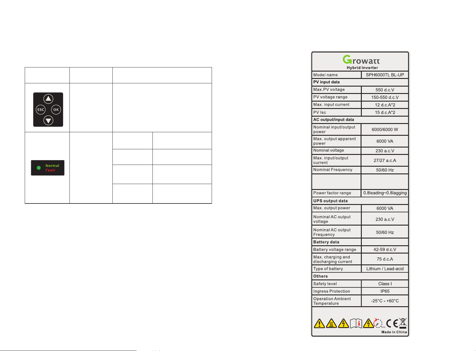
3.2 Label Explanation
Label co nt ains the followin g in formation: fo r ex am ple SPH 6000TL BL -U P shows
as below :
Mark
Descri pt ion
Push-b ut ton
Status s ym bol of
SPH
Explan at ion
Operat io n of display screen and set s ys tem
Green light on SPH run no rm ally
Red ligh t on Fault st at e
Green light
blinki ng
Red ligh t
blinki ng
Alarm st at e
1.bypa ss s tate
2.Soft wa re u pd at ing
Z_souce=1 .0 5+ j 0.32
ohm,Maxim um s ho rtcircuit
27 a.c.A
7 8
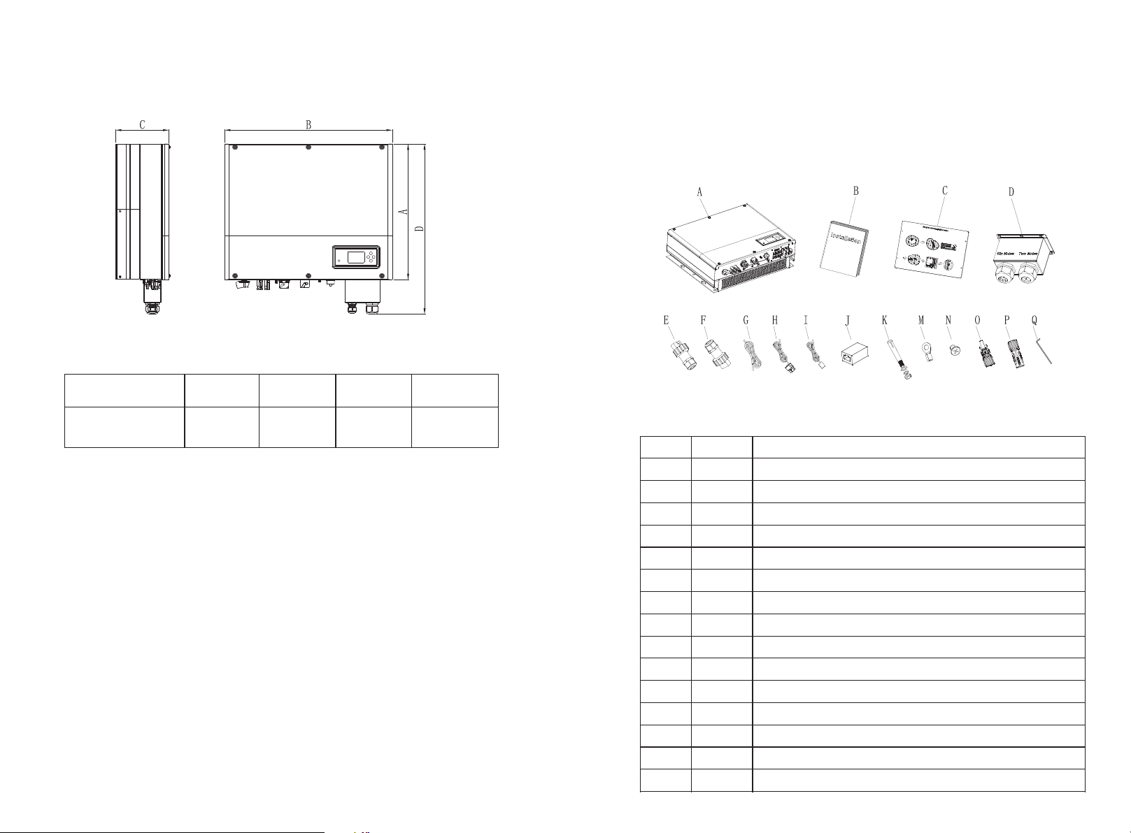
3.3 Size and weight
Unpacking 4
Please c he ck whether external damage to th e go ods before unpacking.
After unpac ki ng, ple ase check whether the unit damage or missing parts, if it is
happen , pl ease contact with s up plier.
Growatt SPH se ri es a nd accessorie s as f ollows:
Chart 3. 1
weight(k g)
27
Growatt SPH
A(mm)
B(mm)
C(mm)
450 565 1 80
3.4 The advantage of the unit of Growatt SPH
Features bel ow :
·All in one d es ign. Can improve self con su mption, back up and a ls o pinch the valle y.
·Smart ma na gement,work mod e ca n be set.
·Safe bat te ry used.
·Easy ins ta llation.
·Two mp p tr ac ker input.
Uninte rr upted power suppl y fo r UPS Load·
9
Item
A
B
C
D
E
F
G
H
I
J
K
M
N
O/P
Q
Number Description
1
1
1
1
1
1
1
1
1
1
4
2
6
2/2
1
SPH inverter
User Manual
Paper board(installation guide)
Wat er proof cover
AC Grid connector(Austri al ia n ma ch in e te rm in al i s di fferent)
UPS output connector
Communication cable
Current sensor
Lead-acid battery temperat ure sensor
RJ45 connector
M6 setscrew
Battery power terminal
Screw
MC4 connector
Hex screwdri ve r
Chart 4. 1
10
5 Installation
5.1 Basic installation requirements
A. The ins ta llation locatio n mu st be suitable fo r SP H' s weight for a long p er iod time
B. The ins ta llation locatio n mu st conforms wit h di me nsion of SPH
C. Do not in st all the unit on struc tu re s co nstructed of flam ma ble or thermo lab il e
materi al s
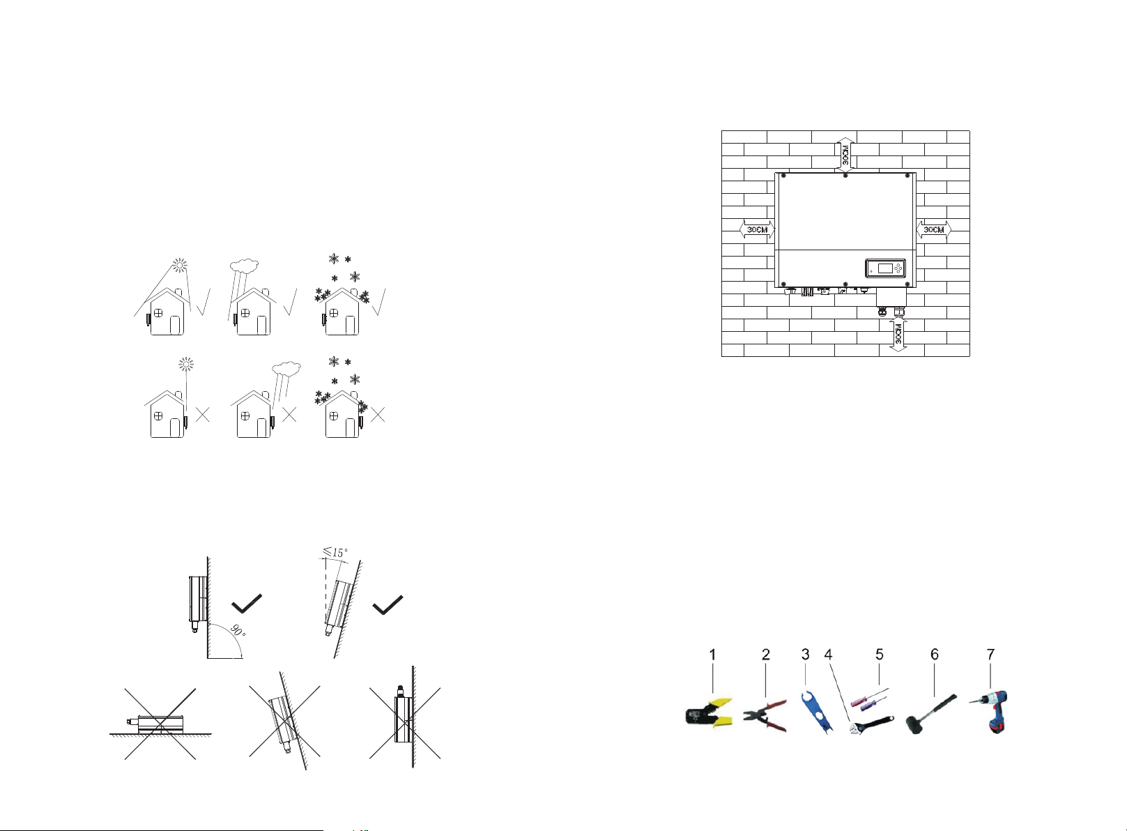
D. The ing ress P rotect io n rate is IP65 and the po ll ution degree is Pd2. and SP H ca n't
be enclo se d.Please refer to the bel ow :
Chart 5. 1
E. Batte ry i nstallation opt io n is not far away from the posi ti on of SPH, the leng th
betwee n SP H and battery shoul d no t be more than 1.5m.
F. The ambient tem pe ra ture s hould be -25℃ ~60 ℃
G. SPH can b e in stalled in vertic al o r lean back on plan e, p lease re fer to the below
H. Insta ll ation position sh al l not prevent access to the d is connection me an s.
I. In order to ens ure mach in e can run normally an d ea sy to operate, pl ea se pay
attent io n to pro vi de adequate spa ce f or SPH, please refer to bel ow :
Chart 5. 3
J. Do not in st all the machine nea r te levision ante nn a or any other antenn as a nd
antenn a ca bles
K. Don't i ns tall the machine in t he l iving area
L. Be sure that th e ma ch ine is out of the chi ld ren' s reac h
M. Taking th e ba ttery fixing spac e in to account, abo ut t he dimensions ple as e
reference user manua l
N. The inf la mmable and explos iv e dangerous goods must no t be p laced around
batter y in c ase of cause seriou s da nger.
5.2 Installation requires tools and RJ 45 terminal sequence
of the LAN line
When ins ta lling,we need to use to ol s as follow,prepare the follow to ol s before
instal li ng:
Chart 5. 2
11 12
Chart 5. 4
No
1
2
3
4
5
6
7
Descri pt ion
Press the RJ45 t er mi nal
Press batter y te rm inal connecto r
Discon ne ct PV terminal
Unscrew nut
Unscrew screw
Knock ex pl osion bolt
Drill ho le s on the wall
5.3 Installation Instructions
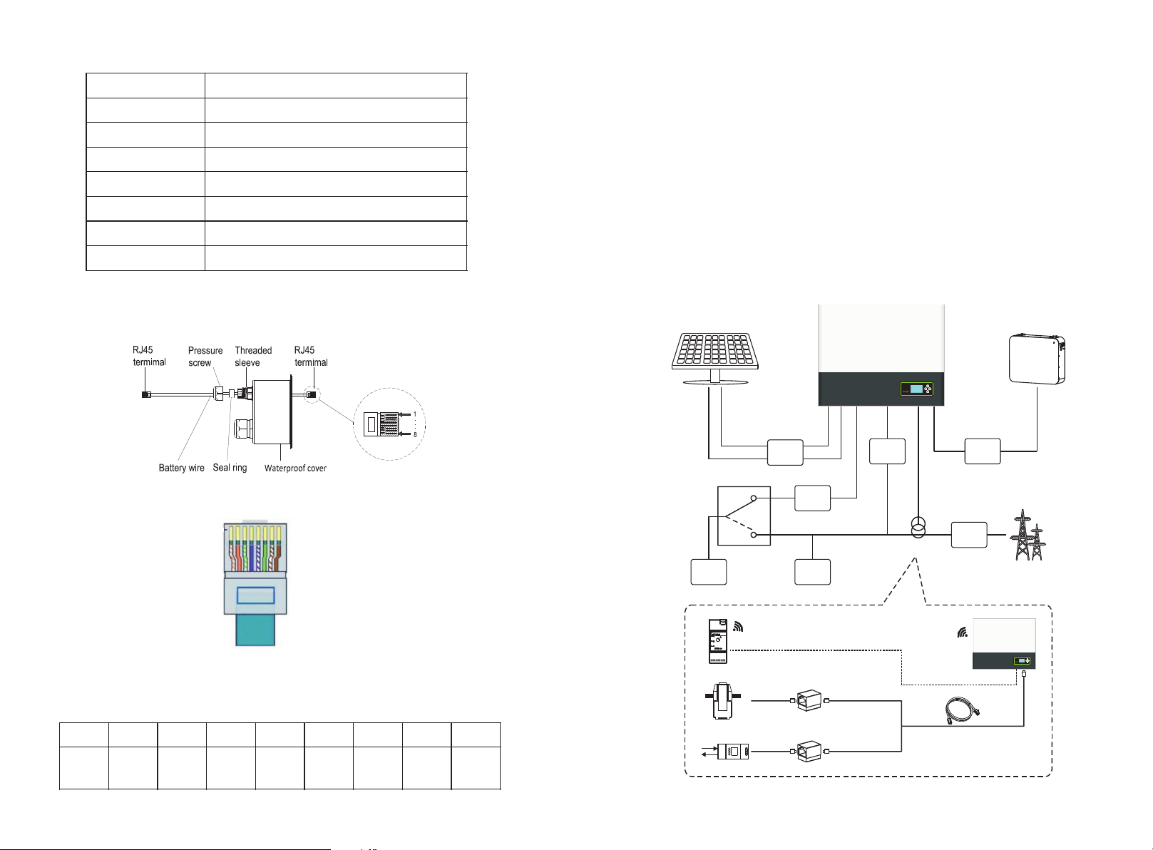
5.3.1 Attention Layout(length of sensors consider)
There're th ree types of sensors for use with Growatt SPH. One is wired current sen so r,
one is meter sensor, or Rail Lo g, i f yo u ch oo se w ired sensor or meter . Before installing
you should know something that as below:
The cable of wired sensor and meter is suggested not longer than 15m. So you need to
consider the length between SPH with combine r bo x fo r th e se ns or s ho ul d be i ns ta ll ed
in the live line. And if you installed RailLog for sensor, dis ta nc e recomm en de d no t mo re
than 30 meters.
The installation layout of energy storag e ma ch in e at h om e as f ol lo wi ng:
LAN line R J4 5 sequence as follo w:
Chart 5. 5
Chart 5. 6
LAN line 1 -8 c olors as below:
PIN 1 2 3 4 5 6 7 8
Color
White
orange
Orange
White
green
Blue
White
blue
Green
White
brown
Brown
PV Array
UPS
Load
1
2
L,N
3
L,N
TSS P(Opt ional )
Rai lLog
Ele ctic me ter
L line
CT
DC
Bre aker
5m
5m
AC
Bre aker
Load
Hybri d In ver te r
UPS Gr id
Bre aker
Chart 5. 7
Senso r
30m
DC
Bre aker
AC
Bre aker
Batte ry
Elect ri cal G ri d
10m
1413
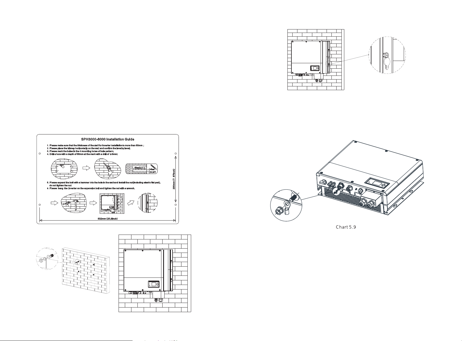
5.3.2 Installation of SPH
1.Project th e ma ch ine's probably size on th e wa ll; The thickne ss o f wall for SPH must
be not les s th an 60mm.
2.Make su re t he drill po si tion, use p aper board(instal la tion guide) , put the p ap er
board cling to the w all, make sure the t op edge of paper board is lev el( As the
chart 5. 8a b elow).
3.Mark four points at the w all v ia the hole of th e pap er board, th en remove the
paper bo ard.
4.Drill f ou r Ф8 holes at the mark poi nt , the depth is not le ss t ha n 55mm.
5.Knock f ou r explosion bolt in toФ8 h oles(As the chart 5 .8 b be low).
6.Hang th e en ergy storage mach in e on the four setsc rews(As th e ch art 5.8c below) .
7.Lock th e nu t of setscrew(As the chart 5. 8d b elow).
8.The who le i nstallation has f in ished.
d)
Chart 5. 8
5.4 Grounding connection
SPH must b e grou nd ed b y cable, the grounding po in t is showed as foll ow, a nd the
minimu m grou nd in g cable wire is AW G1 0.
a)
PV Array G roun di ng
Grounding co nd uc tor of PV panel bra ck ets must be firmly co nn ected to earth at P V
array si de a nd inverter side an d SP s ide. The sectio na l area o f grou nd ing conductor
should b e eq ual to the sectiona l area o f DC g roun di ng conductor. The minimum wire
is AW G10.
DC Grounding
Select t he D C Grou nd ing mode according to the l oc al standard and use the PV
grounding te rm in al box and DC Grounding wires of th e sa me specificatio n.
Grounding De vi ce
If the pos it ive pole or the negat iv e pole of PV array ne ed s to be grou nded in the PV
system , th e inverter output s ho uld be insulate d by I solation Tran sformer. Is ol ation
transf or mer must conform to I EC 62109-1,-2 st an da rd .
Connec ti on as below:
b) c)
15 1 6

5.5 SPH System electrical connection
Decisi ve Vo ltage Class (DVC) i nd icated for port s
Port Nam e
AC
DC
DRMS
RS485& RS 232
Class
C
C
A
A
5.5.1 Connection of PV terminal
The inve rt er shall be used with I EC 6 1730 Class A rati ng
PV modul e.
Please u se t he same brand male an d fe male PV
connec to rs.
Chart 5. 11
Simila r to the t ra ditional i nv er ter connec ti ng, the i np ut of PV p anel energ y can be
realized by us in g MC 4 PV terminal, th e de tail steps are as follows:
1.Tur n off PV switch.
2.Inser t PV pan el positiv e and negative cab le s i nt o M C4 termi na l, t he n c on nect
positi ve pole(+) of connection cable to pos itive pole(+ ) of PV in pu t connecto r,
connec t ne ga ti ve pole(-) of connection cabl e to neg at iv e po le(-)of PV input
connec to r, please p ay attention to PV in put voltage a nd curren t within perm is sion
Limit:
Max PV vol ta ge:550V (consider t he l owest tempera tu re)
Max PV inp ut c urre nt : 12A
Max PV inp ut p ower per string: 40 00 W.
Remark : 1. We s ug ge st you use the cabl e ≥4m m2/12 AW G to c on nect.
2.Plea se d o not connect to DC sou rce!
5.5.2 Connection of AC terminal and off grid terminal
SPH has a g ri d output term in al and off grid out term in al,look down on th e SPH from
the front,the term in al on the rig ht (on gri d) is grid outlet for conne ct ing grid,th e
termin al o n the left is an uninte rr upted power out le t fo r connecting cr it ical load.
17
Chart 5. 12
18

Wi re s ug gest length:
Max cabl e le ngth
Conduc to r cros s
sectio n
2
5.2mm 10 AWG
2
6.6mm 9AWG
AC output terminal and UP S ou tp ut ter mi nal co nn ection s teps a s foll ow (Exce pt for
the Aust ra lian machine):
Growatt
SPH300 0
40m 33m
50m 42m
Growatt
SPH360 0
Growatt
SPH400 0
28m
36m
Growatt
SPH460 0
26m 25m
33m 32m
Growatt
SPH500 0
Growatt
SPH600 0
23m
29m
Step 3:P us h thre ad ed sleeve on to con ne ction terminal un ti l both are locked tightly
Chart 5. 16
Step 4: Plug the s oc ket into AC output termin al a nd U PS output termina l,
clockw is e rota ti on t o tighten the socke t, c ou ntercl ockwise rotation to loose n th e
socket .
Note:T he following diagram s hows th e AC ou tp ut term in al of t he Australian
machin e connection s te ps are as f ol lo ws, UPS output termin al connection steps
consis te nt with the above ste ps .
AC outpu t te rminal connecti on s teps as follow:
Chart 5. 13
Step1: U ni nstall the AC termi na l and UPS termina l as a bo ve chart.
Chart 5. 14
Step 2 : Thread cabl es through pressure screw, s ea l ring, t hrea de d sleeve in sequence ,
insert cables int o connection terminal acc ordi ng to pol ar ities indi ca tes on it and
tighte n th e scre ws .
Chart 5. 15
19
chart 5. 17
Step 1: Un in stall the AC termin al a s above chart.
chart 5. 18
Step 2.Thread cables through pres sure sc rew, seal ring, threaded sleeve in
sequen ce , in sert cables into co nn ection terminal a cc ordi ng t o po larities indi ca te s
on it and ti gh ten the screws.
chart 5. 19
20

Step 3: Push thre ad ed sle eve on to connec ti on ter minal until both are locked
tightl y.
Note: This d iagram i s an exampl e for gird syst em without special requirement on
electr ic al wiring connect io n.
SPHInvert er
chart 5. 20
Step 4: Align th e bayonet o f the A C output te rm inal to t he slot o f threa d sleeve ,
Plug the s oc ket into AC output te rm inal.
chart 5. 21
Step 5:To remove the AC ou tput terminal , p re ss th e bay on et ou t o f the slot with a
small sc rewd ri ve r and pull it out.
The recommen de d wi ring diagram is a s fo llows:
SPH Inver ter
ACG RID
L L
N N
E E
UPS O UTPUT
Bat tery
TSS P
PV
Sens or
L
N
PE
PV
Sen sor
L
N
PE
L LN NE E
ACG RID
L L
UPS O UTPUT
N N
E E
Battery
TSS P
UPS
Chart 5. 23
Note: Thi s d ia gram is an example fo r A us tralian and New Zeal an d g ird s ys tem where
neutra l li ne can't be switche d.
21
L LN NE E
Chart 5. 22
UPS
Chart 5. 24
Note: Th is d iagram is an exampl e fo r customer who on ly w ant to use the on grid
system .
22
SPHInvert er
PV
UPS O UTPUT
L
N
E
L N E
UPS
Battery
Chart 5. 25
Note:
This dia gr am is an example for cu st omer who only wan ts t o us e the off grid storage
system .
Notice :
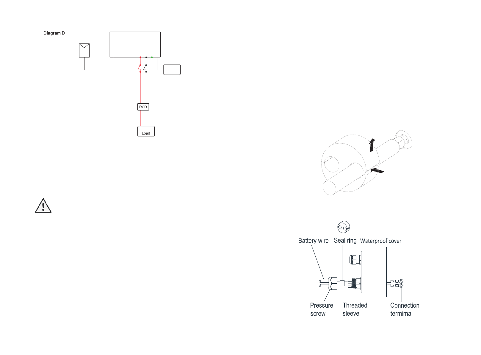
5.4.3 Connection of battery terminal
Instal l ba ttery steps are as follow s:
1.Unsc rew th e sw iv el nut from the cable gland .
2.Thread the s wi ve l nut over the batt er y cable.
3.Press the ca bl e su pport sleeve ou t of t he cable gland.
4.Remo ve t he filler plug from the cab le s upport sleeve.
5.Rout e th e network cable through a n op ening in the cable su pp ort sleeve.
6.Thread the n et wo rk cable through the cabl e gl and.
7.Thread c ables int o connectio n terminal, then press th e terminal by relevant t ools
and ma ke s ure ba ttery cables are fi rm ly (Growatt lithium b at tery contains a b attery
cable in t he o riginal packing ).
8.Conn ec t positi ve pol e ( +) of battery cab le to b at tery positiv e t er minal (+) of the
invert er, connect neg at ive pole (-) of batte ry c able to battery n eg ative terminal (- ).
9.Cont in ue to install other c ab les.
Chart 5. 26
1.If you w an t to use o n gird on ly, p le ase refer to c ha rt 5.24 connect with AC grid and
float UP S OU TPUT.
2.If yo u have no b attery now, you can a ls o float B AT te rminal, and this hybri d inverter
will onl y wo rk like a PV inverter.
3.If you want to use both on gird power and u ninterrupte d p ow er, please refer to
chart 5. 22 a nd 5.23 connect wit h AC g rid and UPS OUTPU T li ke the chart show.
4.On grid t er minal and off grid termin al c an't directly connect t og ether.
5.Off Grid term in al c an't connect to g ri d.
6.If you want to use on gi rd and off grid, you can use T SSP ( transfer switch singl e
phase) like cha rt 5.22 a nd 5.23 b ef ore or as k Grow att for help to connect t he m. TSSP
is using to switch when SPH is not working or in f ault mode. For example: if SPH i s i n
fault mode but there is Gr id power. Turn th e TSSP to Gird to k eep UPS l oad havin g
power.
7.Max UPS l oa d should be less than 3 68 0W.
8.The fir st s tart of system need s Gr id power.
Chart 5. 27
23 24

Chart 5. 28
Note:We suggest the dis ta nc e bet we en ba tt ery a nd SPH n o lon ge r tha n 1.5m, and
the powe r li ne are a mu st be larger than 5 AWG.
5.5.4 Connection of CT term in al
There i s a C T in SPH inverter mo ni toring t he power consumption situation of
residentia l us er s, the CT termina l co nnection steps are as fol lo ws:
1.Unsc rew th e sw iv el nut from the cable gland .
2.Thread the s wi ve l nut over the “CT” c ab le.
3.Press the ca bl e su pport sleeve ou t of t he cable gland.
4.Remo ve t he filler plug from the cab le s upport sleeve.
5.Rout e th e “CT” cable through an ope ni ng in the cable suppo rt s leeve.
6.Thread the “ CT ” ca ble through the cable gla nd .
7.Inse rt th e RJ4 5 plug of the network cable int o the “C T” pi n con nector on the
invert er u ntil it snaps into pl ac e.
8.If no other cables need to be in st alled, lo ck th e waterproof cover t o the inverter
with screws.
9.Screw the sw iv el n ut onto the water proof co ve r.
Chart 5. 30
Chart 5. 31
Note:
1.Mete r a nd CT can't be in st alled at same ti me, please set t he sensor model wh en
select in g CT or electricity m et er, please refer to s ec tion 6.3.3 for deta il s.
2.If the ca bl e such as “ CT ” cabl e is no t used, please do not remove t he fille r plug
from the cable s up po rt sleeve.
Remark :
CT wire (5m in len gt h) s pecificatio n: R J45, standard LAN line (o ne e nd with 8P modular plug, the oth er c on ne cted w ith transfo rm er). B ut if the length is not enough,
custom er can add cable , so th e lengt h can b e increased to 15m max, t he operat io n is
as follo w ch art:
25
Chart 5. 29
Chart 5. 32
26

During the actual ope ration, p le ase pay a ttention to the inst al la tion of c urre nt
transf or mer as the diagram sh ow s below:
Chart 5. 33
As i llustrated above, open th e current t ra nsformer and you can se e an arro w label ed
on i t indicating the direction o f current. Put the live wi re a mong the un der-detectio n
wires on to the current transformer. After latching t he current tran sf ormer, th e
instal la tion has been finis he d
Notice :
The direction (from K to L ) o f t he ar row on the current transform er is co rrespo nd ing
to the dire ct ion of the curren t i n live wire from Grid to Load. Senso r n eeds to be
placed i n th e power distribut io n cabinet.
5.5.5 Connection of meter terminal
When custome r need s to use meter to monitor the energy flow, the meter terminal
connec ti on steps are as follows:
1.Refe renc e 5. 2, m ake LAN cables wi th R J45 terminal.
2.Thread the s wi ve l nut over the LAN ca bl e.
3.Press the ca bl e su pport sleeve ou t of t he cable gland.
4.Remo ve t he filler plug from the cab le s upport sleeve.
5.Rout e th e LAN cable through an open in g in the cable suppor t sl eeve.
6.Thread the L AN c ab le through the cable glan d.
7.Inse rt t he RJ45 plug of the net wo rk c able into the “48 5- 1” p in connector on t he
invert er u ntil it snaps into pl ac e.
8.If no other cabl es need to be i nstalled, lo ck the waterp roof co ver to th e i nverter
with screws.
9.Screw the sw iv el n ut onto the water proof co ve r.
Chart 5. 35
Note:
1.Mete r a nd CT can't be in st al led at same ti me , p lease set the se ns or model when
select in g CT or electricity m et er, please refer to s ec tion 6.3.3 for deta il s.
2.Mete r must be provide d by G ro wa tt. If not, m aybe m eter c an't commun ic ate
with SPH i nv erter.
3.The mo re det ai l de scribe of meter i ns tallation, plea se t urn to mete r us er manual.
5.4.6 Connection of communication terminal of lithium
battery (CAN)
When using CA N communic at io n with lithium ba tteries (f or examp le PYLON
US2000 B) , connect lithium b at tery terminal ( RJ 45 ) steps as follow s:
1.Unsc rew th e sw iv el nut from the cable gland .
2.Thread the s wi ve l nut over the “CAN ” ca ble.
3.Press the ca bl e su pport sleeve ou t of t he cable gland.
4.Remo ve t he filler plug from the cab le s upport sleeve.
5.Rout e th e “CAN” cable through an op en ing in the cable supp or t sleeve.
6.Thread the “ CA N” c able through the cable gl an d.
7.Inse rt the RJ45 plug of th e n et work cable into the “CAN” pin connector on the
invert er u ntil it snaps into pl ac e.
8.If n o other c ables need to be i ns talled, l oc k the w at er proo f cover t o the i nv er ter
with screws.
9.Screw the sw iv el n ut onto the water proof co ve r.
27 2 8
Chart 5. 34
Chart 5. 36

Chart 5. 37
Note:
1.If yo u are using a lea d- acid battery, you do n ot need to ins ta ll this commu ni cation
cable.
2.The CAN batte ry communica ti on and 485- 2 battery c ommunicatio n can't b e
instal le d at same t im e, please s el ect the cor rect c ommunication me thod according to
the batt er y manual.
3.If the cable such as “485 -2 ” cab le or “CAN” cable is not used, please do not
remove the fil le r pl ug fro m the cable support s le eve.
Chart 5. 39
Note:
1.If you are u sing a lead-ac id batte ry, yo u do no t need to ins ta ll thi s
commun ic ation cable.
2.The CAN bat te ry commu ni cation and 485-2 battery co mmunication can't be
instal le d a t same time, please sele ct the correct communic at ion m et hod a ccordi ng
to the bat te ry manual.
3.If the cable such as “485-2” cable or “CAN” cable is not used, please do not
remove the fil le r pl ug fro m the cable support s le eve.
5.5.7 Connection of communication terminal for lithium
battery (RS485)
When using lithiu m bat te ri es wh ich n eed t o con ne ct BM S s ys te m o f the battery,
connec t li thium battery ter mi nal (RJ45) step s as f ollows:
1.Unsc rew th e sw iv el nut from the cable gland .
2.Thread the s wi ve l nut over the “RS4 85 ” cable.
3.Press the ca bl e su pport sleeve ou t of t he cable gland.
4.Remo ve t he filler plug from the cab le s upport sleeve.
5.Rout e th e “RS485” cable through a n op ening in the cable su pp ort sleeve.
6.Thread the “ RS 48 5” cable through the cabl e gl and.
7.Inse rt the RJ45 plug of t he netwo rk cab le into the “RS485-2” pin connector on
the inve rt er until it snaps int o pl ace.
8.If no ot her cables ne ed to be install ed , lock the wat er proo f cover to the in verter
with screws.
9.Screw the sw iv el n ut onto the water proof co ve r.
Chart 5. 38
29 3 0
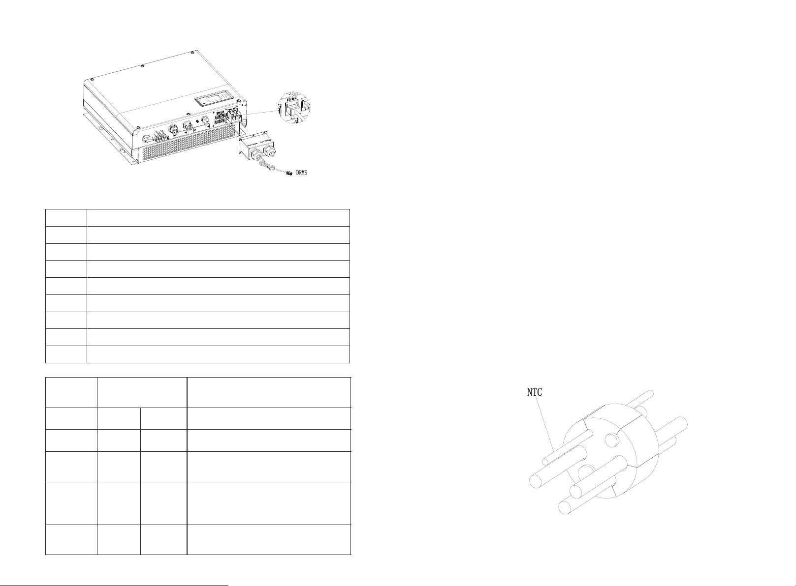
5.5.8 Connection of DRMS terminal
The DRMS t er minals need to be con ne cted ,the conne ct ion way appears as fo ll ows:
1.Unsc rew th e sw iv el nut from the cable gland .
2.Thread the s wi ve l nut over the “DRM S” c able.
3.Press the ca bl e su pport sleeve ou t of t he cable gland.
4.Remo ve t he filler plug from the cab le s upport sleeve.
5.Rout e th e “DRMS” cable through an o pe ning in the cable sup po rt sleeve.
6.Thread the “ DR MS ” cable through the cable g la nd.
7.Inse rt t he RJ45 plug of t he network ca bl e into the “D RM S” pin connec to r on the
invert er u ntil it snaps into pl ac e.
8.If no other cables need to be inst al led, lo ck the w at erproo f cov er to the inverter
with screws.
9.Screw the sw iv el n ut onto the water proof co ve r.
Chart 5. 40
MODE
RJ 45 sock et a sserted
by short in g pins
Requiremen t
DRM0
5
6
Operat e th e disconnection d ev ice
DRM515
Do not gen er ate power
DRM625
Do not gen er ate at more than 50% of
rated po we r
DRM7
3
5
Do not gen er ate at more than 75% of
rated po we r and sink reactive power i f
capabl e
DRM8
4
5
Increase pow er g en eration (subj ec t to
constr ai nts from o ther active DRM s)
Note:
For UK:Thi s eq uipment is equipp ed w ith RJ45 termin al f or l ogic interfac e th at
being receiv ed t he s ignal from the DNO, the con ne ction should be i ns talled per
instal la tion manual, and th e si gnal should be a si mp le b inary output th at c apture d
by RJ45 te rm inal( PIN 5 and 1 for det ec ting the signal ). O nc e the signal acti ve d, the
invert er w ill re du ce its active pow er t o zero w it hin 5s.
Note:
If the cab le s uch as “NTC” (lead- ac id battery temp er ature se nsor) cable is no t
used, pl ea se do not re move the filler p lu g from t he c able support sl ee ve.
Chart 5. 41
RJ45 ter mi nal pin assignmen t
PIN
1
2
3
4
5
6
7
8
Method o f as serting demand respon se m odes
Assign me nt for inverter sca pa ble of both charg in g and discharging
DRM5
DRM6
DRM7
DRM8
RefGen
COM/DR M0
/
/
5.5.9 Connection of temperature probe for lead-acid battery
When cus to me r using lead-acid b at tery, the tempe ra ture p robe o f th e le ad-acid
batter y is u sed to detect the a mb ient temperat ure of t he l ea d-acid batter y, the
batter y te mperature cable of the SP H si de connection ste ps a re a s fo llows:
1.Unsc rew th e sw iv el nut from the cable gland .
2.Thread the s wi ve l nut over the “NTC ” ca ble.
3.Press the ca bl e su pport sleeve ou t of t he cable gland.
4.Remo ve t he filler plug from the cab le s upport sleeve.
5.Rout e th e “NTC” cable through a min o pe ning in the cable sup po rt sleeve.
6.Thread the “ NT C” c able through the cable gl an d.
7.Inse rt the RJ45 plug of t he network cab le into t he “NTC” pin con ne ct or on t he
invert er u ntil it snaps into pl ac e.
8.If no other cables need to be installed, lock th e wat er proo f cover to the inverte r
with screws.
9.Screw the sw iv el n ut onto the water proof co ve r.
Chart 5. 42
31 3 2

Chart 5. 43
Note:
1.If yo u are using a lit hium battery, you do not need to ins tall this tem perature
probe, the p ro be of the temperature cable should be attache d to the surrounding
environmen t o f t he lea d- ac id battery, a nd the length o f t hi s c able is 1.5m, so pay
attent io n to the distance of ba tt ery and SPH.
2.If th e cab le such as “NT C” (l ead-acid bat te ry temperature sens or ) cable is not
used, pl ea se do not re move the filler p lu g from t he c able support sl ee ve.
5.5.10 Connection of Dry contact
The dr y contact is used to commun ic at e with ex ternal devices ( su ch as remot e start
hot wate r he ater). The wiring s te ps are a s follows:
1.Unsc rew th e sw iv el nut from the cable gland .
2.Thread the swi ve l nut over the cabl e.
3.Press the ca bl e su pport sleeve ou t of t he cable gland.
4.Remo ve t he filler plug from the cab le s upport sleeve.
5.Rout e th e network cable through a n op ening in the cable su pp ort sleeve.
6.Thread the net wo rk cable through the cabl e gl and.
7.Thread cab le s into connec ti on terminal o f th e inverter, then press the ter mi nal by
relevant too ls a nd m ake sure cables are firmly.
8.If no ot her cables ne ed to be installed , l ock the water proof c ov er to the inve rt er
with screws.
9.Screw the sw iv el n ut onto the water proof co ve r.
Chart 5. 45
Note:
If t he cabl e such as “D ry contac t” cable is no t used, please d o not rem ove the filler
plug from the ca bl e su pport sleeve.
5.5.11 Tighten the waterproof cover
When all the co mmunication lines are in stalled, push the wa terpro of c ov er i nt o th e
bottom , lo ck the screws fixed to the fr am e, and finally lock t he w aterproof cap.
33
Chart 5. 46
Chart 5. 44
34

6 Commissioning
6.1 Commissioning of SPH
Electr if y SPH after all insta ll ation of Part5 be f in ished, here are the steps:
1.Conn ec t PV
2.Conn ec t AC
3.Conn ec t battery
4.Turn on PV first
5.Then t ur n on Grid
6.Last t ur n on batter y
If PV Gr id and battery are available, system would work on th e “ no rmal” mode.
When the SPH on t he no rmal mo de, t he sc re en show in g “ No rmal”, LED i s g reen . If
SPH no t enter norma l mode succ es sf ul, especia ll y the LCD i s re d, you need t o check
below:
1.Make s ure al l th e co nnection is cor rect.
2.All th e ex ternal sw it ches are o n.
3.Inve rt er built -in switch i s on .
4.Make s ure th e li th ium battery is on .
5.Refe r to P art 9.1 for correction.
You ca n refe r to P ar t 6.3.4 for work mo de s et ting, then conf ig ure mo ni tor, finish
commis si oning lastly.
The SPH in ve rter will be set to the a pp ro pr iate model according to t he s tandards of
different countrie s or reg io ns b efore leaving the fac to ry. For examp le , th e inverter
shippe d to A ustralia are configured as Aust ra lian model in the f ac tory.
Note: Th e in verter is configu red fo r Au stralia at the fact or y.
2.Batt er y first: Wh en SPH workin g in this mod e, battery woul d be charged fi rst, it's
suitab le working o n the per io d when the elect ri c charge is low. User need to set
the mode ON and OF F time , and t he end time o f battery SOC. Us er can set po wer
rate which less than the batter y max im um ou tput power. If the cust om er don't
enable t he A C CHG (AC grid chargi ng f unction). Inv er te r will charge bat te ry by PV
power as large as it can d o. If th e cus to mer e nable the AC CHG ( AC gr id ch arging
functi on ). Inv er ter will charge b attery b y PV power and AC power from grid as
large as i t ca n do.
3.Grid -f irst : When SPH w or king in Grid- fi rs t mode, the PV en er gy would feed t o
Grid f ir st . User can ch oo se t he period w he n electric char ge i s high. User ne ed t o set
the mode ON and OF F time , and t he end time o f battery SOC. Us er can set po wer
rate whi ch l ess than the batter y ma ximum output po we r.
Backup m od e
If Grid lo st, system woul d t urn to ba ck up mode (user ca n disable it, refer t o 6 .3.4)
and UPS OU TP UT will keep poweri ng t he load, all the en er gy fro m PV a nd battery, if
the PV also los t, th en only battery discha rg e. Mind you, SPH maximu m out put
power is 3600 W in this mode, th e load which conn ec t with UPS LOAD should l es s
than 360 0W.
6.2 Operation modes
6.2.1 Normal mode
Normal m od e is working state wh ic h including onl in e mode and backup mod e.
Online m od e
User can set an appropriate priorit y mod e acc ordi ng to request when SPH workin g
on t he online m od e. If cus to mer use t he LCD an d key setti ng s, you ca n only set one
period , but if you use website settings , you can set up to thre e perio ds of the
priori ty m ode. .
(refer to 6.3.4)
1.Load fir st: Load f irst is the default mod e, when it's w orking i n this mod e, PV
energy would offer to load and battery prior; when PV is Insufficient, battery
would di sc harge; when PV is s uffici en t for load ,the exc es s en ergy would feed t o
batter y. If there is no battery or bat te ry is f ull ,the excess energ y w ould feed to
Grid(e xc ept anti -reflux ).
35
Notice :
1. U ser onl y can s et one period for bat te ry firs t and G rid fir st on the LCD,if user
need set m ore pl ea se l ogin shineser ve r.
2.If us er need Gri d charge ba tt ery, us er need input p assword on th e SC surfac e and
set the AC C HG t o enable .
6.2.2 Bypass mode
The SPH's intellig en t con trol system could monitor and adjustm en t sys te m's s ta tus
contin uo usly, when S PH inve rt er moni to ring an yt hing un ex pected happen, s uch a s
NO PV and NO batte ry ,t he LCD will display the by pa ss in formation, in byp as s
mode, th e Re d LED light will be Bli nk ing. Grid will su pp ly t he power to UPS loa d.
Notice :
If there are some fault in b yp ass mode. LCD will di sp lay error also.
36

Cautio n :
When you s et ting the DIP, you must turn o ff
PV switc h, A C brea ke r and Battery to ma ke
sure all of the po we r are off.
Cautio n:
1. After s et ting the DIP, please power on t he
invert er a nd check the model di sp lay (show
as 6.3.1 ). I f the model display i s ma tch what
you want , it m eans your setting i s su ccessful.
2. You n ee d to calibrate th e ti me that the
machin e is s howing after inve rt er starts up.
If the cou nt ry is set incorrectly, pl ease shut
down the i nv erter and set again .
6.2.3 Fault mode
The SP H' s intellige nt control system c ould monito r and adjustm en t system's st at us
contin uo usly, when SPH inverter monitor in g a nything unexpected hap pe n, such
as NO PV and NO batt er y ,t he LCD will display the b yp as s information , in b yp as s
mode, th e Re d LED light will be Bli nk ing. Grid will su pp ly t he power to UPS loa d.
Notice :
If there are some fault in b yp ass mode. LCD will di sp lay error also.
6.2.4 Programming mode
Programmin g mode i nd icates t he S PH is updat in g ,don't cut out power whe n it's
updati ng u nt il the pro cessing is finish ,S PH i nverter would log out a ut om atically
when the u pd ating finish and tu rn to other mod e .
6.2.5 Checking mode
Before SPH wo rk in normal mode, it w il l go to s el f-check mode. If all are ok , syst em
will go to n or mal mode , otherwis e, i t will go to fault mo de .
6.2.6 Standby mode
If th e system hasn't fau lt while the cond it io n is no t qualif ie d, SPH woul d stay at
standb y mo de.
6.3 Country setting
Growatt can provide va ri ous re gu lations of the ma ch ine, after custom er s re ce ive
the mach in e, according to their cou nt ry, by dialin g DI P switch to set the
correspond in g regu la tions. Followin g is t he DIP switch int roduct io n.
Chart 6. 1
6.2.7 Shutdown mode
If cu st omer nee d SPH inver te r stop wo rking, cus to mer must disconnect all the
energy s ou rc e, t he n SPH inverter wi ll t urn into sh ut down mode automat ic ally.
The foll ow ing is the shutdown p roce du re:
1. Shutd ow n the PV side
2.Turn off battery swit ch .
3.Shut down AC power of SPH . Then you can se e th e both LED and LC D of SP are
off.
Notice :
After al l th e actions are done, you sti ll h ave to wait for more than 5 min ut es.
37 3 8
The DIP sw it ch is composed of six -d igit binary num be r PI NS. The different
combin at ion of the six PINS can represent different inv er te r's model, whic h is
correspond in g to t he local grid sta nd ard. E ac h small white PIN h as t wo statuses,
when set u pw ard to “ ON ”, its value turns to “1”, when se t do wn ward , its value
turn s to “0”. Concerning the match in g of t he PIN status and t he c ountry safety
standa rd, pl ea se ref er t o the table below:

6.3.1 Switch to country table
6
54321
ON
DIP
6
54321
ON
DIP
6
54321
ON
DIP
6
54321
ON
DIP
DIP swit ch s tatus
Countr y/ re gi on / reg ul ations
Model di sp lay
654321
ON DIP
Thaila nd P EA*
T0XXXX XX FG
654321
654321
DI P
654321
654321
54321
6
654321
654321
654321
ON D IP
ON
VDE 0126 *
AS4777 -A ustralia*
GT0XXX XX X1
GT0XXX XX X3
ON DIP
EN5043 8- Irel an d*
DK1(Da nm ark)*
New Zeal an d*
ON DIP
CEI 0-21 *
GT0XXX XX X4
France *
ON DIP
G99*
GT0XXX XX X5
South Af ri ca
ON DIP
VDE-AR -N 4 105*
GT0XXX XX X7
Note:
GT1XXX XX X3
GT1XXX XX X7
GT1XXX XX X8
GT1XXX XX X9
GT1XXX XX XC
“*”mea ns t hat we didn't do the ce rt ification, bu t ca n me et with the requirement.
ON DIP
ON DIP
G98*
En5054 9*
GT0XXX XX X8
GT0XXX XX X9
39
654321
654321
654321
ON DIP
ON DIP
ON DIP
Poland *
Hungar y*
Thaila nd M EA*
GT0XXX XX XB
GT0XXX XX XC
GT0XXX XX XE
40

6.4 Display and button
Locati on
Descri pt ion
A
State
B
Inform at ion
C
D
SPH inve rt er
E
Power fl ow l ine
F
Grid
G
H
Local lo ad
I
Wi re le ss communicatio n
J
RS 232
K
RS 485
L
Buzzer (R eserved)
M
War ning
N
Fault
Location
Descripti on
Status
ESC- button (c an cel control )
Down-butt on
Enter-butt on
UP-button
6.4.1 LCD display area
6.4.2 LED and button instruction
Chart 6.3
Chart 6.2
PV input ( If y ou c onnect two tracks , it w il l show two.
Otherw is e sh ow one)
Batter y (S how the SOC in five gri d, E very grid represents 20%)
A
B
C
D
E
Notice:LED sh ow in g status of SPH, it h as t wo c ol or, on e is g reen and an ot he r is red. Ple as e
turn to 3.1 and rea d th e detail of LED.
6.4.3 LCD display column
LCD display c ol um n is used to show the c ur rent state, b as ic i nf ormation an d fa ul t in formation.
Also includ e la ng uage setting, p rogram chargi ng /d is charging pr io ri ty a nd system time. O n
default con di ti on will take turns to dis pl ay t he i nformation.
Chart 6.4
41 4 2

The A line's co nc lu ding informat io n as f ol low:
WorkMode WorkMode
Language
WorkMode
English
Italian
German
WorkMode
System time
WorkMode
xxD/xxM/xxxxY
WorkMode
Lead-acid CV
WorkMode
58.0 V
WorkMode
Lead-acid CC
WorkMode
75 A
Press “enter” key more
than 1 seconds to make sure
Press “down” key
to the next item
Press “enter” key more
than 1 seconds to make sure
Range from 55 to 60V,
and the accuracy is 0.1V
Range from 0 to 75A, and
the accuracy is 0.1A
WorkMode
Lead-acid LV
WorkMode
48V
Range from 42 to 50V,
and the accuracy is 0.1V
Basic Parameter
Only display when
battery type is lead-acid
Only display when
battery type is lead-acid
Only display when
battery type is lead-acid
WorkMode
Input&Output Para
WorkMode
(Lead acid)Vb:xx.xV
(Lithium)Vb/Cb:xx.xV/xxx%
WorkMode
Vpv:xxxV/xxxV
WorkMode
Ppv:xxxxW/xxxxW
PV1/PV2 voltage
Battery information
WorkMode
Grid:xxxV/xxHz
WorkMode
UPS:xxxV/xxHz
WorkMode
Po:xxxxW/xxxxVA
Grid information
Output AC Power
UPS output voltage
WorkMode
UPS:xxxxW/xxxxVA
WorkMode
Pbat: (+/-)XXXX W
Battery power
UPS output power
WorkMode
Epv_d:xxxx.x KWh
WorkMode
Epv_a:xxxx.x KWh
WorkMode
Ec_d:xxxx.x KWh
WorkMode
Ec_a:xxxx.x KWh
WorkMode
Ed_d:xxxx.x KWh
WorkMode
Ed_a:xxxx.x KWh
WorkMode
SerNo:xxxxxxxxxx
PV1/PV2 today energy
PV1/PV2 total energy
PV1/PV2 input power
BAT Charge_today
energy
WorkMode
Pm: (+/-)XXXXW
Power to grid or to user
BAT Charge_total
energy
BAT Discharge_today
energy
BAT Discharge_total
energy
WorkMode
20XX/XX/XX/ XX:XX
System Time
WorkMode
Model:xxxxxxxxxx
WorkMode
FW Version:xxxx
WorkMode
Eac_d:xxxx.x KWh
WorkMode
Eac_a:xxxx.x KWh
AC output_Etoday
AC output_Etotal
To grid is -
To user is +
Serial number
Machine model
Firmware version
Basic Parameter
WorkMode
WorkMode
Configuration
WorkMode
MODE Change
WorkMode
Priority
WorkMode
BackUp
Press “enter” key more than
3 seconds into setup mode
Press “down” key
to the next item
Press “enter” key more
than 1 seconds to make sure
Default Set
WorkMode
Auto Test
WorkMode
ExportLimit
WorkMode
1. St an db y st ate: SPH is in st an db y st ate. No error i n th is state, but for o th er reasons, m ak e it i n a
wait state.
2. No rm al s ta te: SPH is normal w or ki ng state.
3. By pa ss s ta te: Grid power th e UP S lo ad state while SP H in ve rt er can't powe r UP S lo ad .
4. Ch ec ki ng s tate: SPH is in sel f- ch eck state, if the re is no erro r or w ar ni ng , SP H will go to norm al
state or stan db y st ate. Otherwis e it w il l go t o fault state .
5. Pr og ramming sta te : SP H is i n updating firm wa re state.
6.Fault sta te : SP H has fault infor ma ti on , it will be in sto pp ed o pe rational prot ection state.
Note:
1.“Dow n” control co mm and (if pushing “u p” button , command w ill go back)
2.Workmode depend o n the s it uation. I f SPH i s normal st ate, it will sho w
”norma l” . If SP H is st an dby state , it wi ll show a s “standb y” etc.
3.Some special de finitions a re explained, for ex am ple: Vb means th e voltage o f
batter y. Cb m eans the capacity of lithiu m battery (only li th ium batte ry show t hi s
data). Pm mea ns the mo ni tor power of use r.
The B line's information as follo w:
In n or mal, it will tur n on page au to ma tically, when pu sh ing the button “ UP ”, the
order of the pa gi ng inform at ion as fo llow:
6.4.4 Work mode set up
Keep p re ss ing “ente r ”for 3S ,you can enter s et up sur fa ce,in the set up surface you
need h old but to n Enter o r ESC 1 S for s election,you can see the su rf ac e as sh owing
below.
Chart 6.6
If you cho os e CEI and used SPH inve rt er in Italy, SP H in verter have Aut o Test f unction.
How to use t he A uto test function . Pl ease see the anne x.
1.Unde r th e Basic Para ,you can s ee t he setup option s be low after pressing Ente r fo r
1S:
43
Chart 6.5
Chart 6.7
44

In t he basic Parameter,y ou can set langu ag e ( English ,I ta lian ,G er ma n ),sys te m time ,
WorkMode
ExportLimit
WorkMode
WorkMode
ExportLimit: OFF
ON
Power Rate: 00.0%
Press “enter” key more
than 1 seconds to make sure
Press “down” key
to the next item
Press “enter” key
to make sure
Range from 00.0% to 100.0%,
and the accuracy is 0.1%
WorkMode
Fail Safe: ON
OFF
MODE Change
WorkMode
Sensor
WorkMode
Cable CT
WorkMode
Meter
Raillog
Battery Type
WorkMode
Lithium
WorkMode
Lead-acid
Press “enter” key to
make sure
Press “down” key
to the next item
Press “enter” key
to make sure
lead-a ci d cell ch arging vo lt age (de fa ult is 58 V),discharg e low v ol ta ge (def au lt is
48V)an d lead-acid constant c urre nt(default is 75A).
2.Under the Ba ck Up ,yo u can s ee the se tup optio ns below af ter pressing Enter f or 1S:
In t he back u p you c an set UPS ,incl ud ing enabl e or di sa bl e (defa ul t is en ab le ),AC
voltag e( default i s 230V) a nd frequency(de fa ult site 50HZ).
3.Under the Pr io ri ty ,you can see the set up options below a ft er pressing E nter:
Note:
1.”Pow er R ate” is used to set up po we r of battery. So di ff erent ba tt ery may has the
different power, cus tomer need to che ck t he max power of bat te ry.
2.Time setting is 2 4- ho ur. If the en d ti me i s less than begin ni ng time, it default s to
spanni ng d ays.
45
Press “ente r” key more
than 1 seco nd s to make sur e
Work Mode
BackU p
UPS setup
WorkMode
Priority
WorkMode
Opt: Load First (default)
Bat First
Grid First
If battery first is choosen
Press “down” key
to the next item
If Grid first is choosen
Chart 6.9
Chart 6.8
WorkMode
Bat First: OK
NO
WorkMode
Grid First: OK
NO
Press “ente r” key more
than 1 seco nds to make s ur e
Work Mode
Backu p: E na ble
Press “down” key
Disab le
to the ne xt i te m
Work Mode
ACVolt: 230 V
240
208
Work Mode
Work Mode
AC Freq: 50 Hz
60
If you need to enable AC charging
choose “OK” to
the next item
choose “OK” to
the next item
Press “down” key
to the next item
function, you need key password
Stop SOC: 100%
Power Rate: 100 %
Stop SOC: 5%
Power Rate: 100 %
WorkMode
SC : _ _ _ _
WorkMode
Time
WorkMode
WorkMode
WorkMode
Save :OK
NO
WorkMode
Time
WorkMode
WorkMode
WorkMode
Save :OK
NO
WorkMode
AC CHG: Enable
Disable
WorkMode
00:00 – 00:00
Range from 50 to 100%,
and the accuracy is 1%
Range from 10 to 100%,
and the accuracy is 10%
WorkMode
00:00 – 00:00
Range from 50 to 100%,
and the accuracy is 1%
Range from 10 to 100%,
and the accuracy is 10%
4.Under the MO DE Change , you can see the setup o pt ions belo w after p ress in g Enter:
Chart 6.10
The MO DE chan ge has tw o options what are s en sor and battery ty pe,sensor i s
cable CT(default) ,m eter and SP-CT(wireless RF transf er ).In th e battery t ype,you
can ch oose li th iu m batte ry or lea d- acid ba tt er y.
5.Unde r th e ExportLimit, yo u ca n see the setup opt io ns below after pressing E nt er :
Chart 6.11
Export li mit is used for users t o co ntro l the energy flowin g to t he grid. If this
functi on i s enabled, the feed in g power to grid wil l be e qual or less than the s et up
value. Th e purpose of the Fail S af e function is to en su re tha t sh ould any part of th e
ELS fail , th e Active Power expo rt ed across the Connectio n Po int will drop to the
Agreed Expor t Ca pa city or less with in t he specified time .
Note:
1.Defa ul t value is 00.0%.
2.Fail s af e works only in meter m od e.
3. Fail sa fe w orks only in G99 or G98 c er tification.
4. If Expo rt limit function is w or king, we can't se tu p priority of Grid fi rs t.
6.Unde r the d ef au lt set ,you ca n see the setup op tions bel ow after pres si ng Enter:
Press “en te r” key to mak e
sure
Work Mode Work Mode
Defau lt S et
Press “en te r” key more
than 3 seconds to ma ke s ure
YES
Chart 6.12Chart 6.1
Defaul t set i s “resume to default s et ting ”, pl ea se don' t use it unless it 's necess ar y.
46

6.5 Communication
6.5.1 Use of USB-A port
USB-A po rt i s mainly for firmwa re upd ag e:
Through USB co nn ec tion,we can qui ck ly update the softw are of m ac hine.
You ca n se e USB-A as below.
Chart 6. 13
Note:
USB can be used for firmware update and monitoring . Cus to me r can 't use it for
chargi ng .
6.5.2 Use of RS232 port
RS232 port is mainly used for monitoring conn ec tion with PC , u se rs ca n m on itor ,s et
parame te rs an d updat e the software of t he ma ch ine t hrough RS23 2 conne ct io n w it h
machin e an d PC, using the shine bu s software developed by G rowa tt .
About ShineBus software, when you ne ed ed, plea se downloa d from official website
of Growatt.
Removi ng R S232 cover first:
Chart 6.15
The wiri ng d iagram is as follow s:
Chart 6.16
About Sh in eBus software, when you n ee ded, please downl oa d from o ffic ia l website
of Growatt.
Chart 6.14
Before u se RS23 2 communica ti on, you should ma ke sure the fol lo w PIN1 and PIN 2
are OFF:
47
6.5.3 The SPH's monitoring
The SPH provid e RS 23 2/USB interfa ce . Users can through the fol lo wing
commun ic ation solution to m on itor the SPH. For e xa mple Using Wi -Fi-S monitor
SPH as fol lo w:
Note:
This kind of m onitoring ca n only be used b y the m on itor of Gro wa tt's Shi ne server
/shine phone provid ed by t he company. Through RS 232 inter fa ce connec t to Wi-FiS/shin el ink/GPRS, use com pu ter terminal/ or m obile phone for dat a mo nitoring.
Chart 6.17
Before use WIF I co mm unication, yo u sh ould make sure the follow P IN 1 and PIN2
are ON:
48

Chart 6.18
Then Plu g in t he communicatio n mo dule and tighte n th e sc re ws a s follow.
Chart 6.19
Start-up and shut down SPH system 7
7.1 Start-up the SPH system
Users ca n st art-up SPH invert er s thro ugh following ste ps:
1.Conn ec t to PV
2.Conn ec t to Grid
3.Conn ec t to Battery
4.Turn the switch o n in t urn of PV, Grid and bat te ry.
5.When t he L ED turns green, the w or king informat io n on L CD indicates th e
succes sf ul start-up of SPH in ve rter
7.2 Disconnect the SPH system
Attention of the installation environm-
8
ent, maintenance and cleaning
Heat dis si pation performa nc e is very importa nt w hen SPH inverter wo rk u nder the
environmen t of h ig h temperature, better h ea t dissipation c an reduc e th e
possib il ity of SPH inverter s to ps working. Growatt SPH s er ies inverter wi th ou t fan
so belon gs t o natural cooling , ho t air from the top of the radia to r, tie-in bat te ry,
use envi ronm en t fo r IP65, please pa y at tention to the temp er ature of the
instal la tion environment, to en su re tha t th e battery's saf et y and the normal work
of the mac hi ne.
When use b at tery, pleas e pa y attention to the fo ll ow informatio n:
Cautio n: D o not dispose of batt er ies in a fire. The batterie s ma y explode.
Cautio n: D o not open or damage ba tt eries. Releas ed e le ctro lyte is harmful t o th e
skin and e ye s. It may be toxic.
Cautio n: A b attery can present a risk o f el ectrical shock an d hi gh short-circuit
current. The f ol lo wing precautions shou ld b e observed when w or king on batteries :
a)Remo ve w atches, rings or ot he r metal objects .
b)Use to ol s with insulated ha nd les.
c)Wear rubbe r gl ov es and boots.
d)Do not l ay t ools or metal parts o n to p of batteries.
e)Disc on nect charging sou rce pr io r to connecting or di sc onnecting bat te ry
termin al s.
f)Dete rm ine if battery is ina dv ertently grounded. If i na dvertently grounded ,
remove source from ground. Contact w it h any part of a grounded batt er y can
result in elec tr ic al shock. The lik el ihood of such shock c an b e re du ced if such
grounds are removed during i ns ta llation and mai nt enance (applica bl e to
equipm en t and re mo te battery supp li es not having a grounded su pp ly circu it).
If SPH inv er ter doesn't work fo r ov erheating or to o co ld, solve it according to t he
follow in g methods
·C
onfirm w he ther the radiator a ir d uct installat io n is rea so nable, choose t he
appropriat e po si tion before installat io n.
·
If lead- ac id batteries are connec te d, confirming the N TC b attery is in a good
instal la tion.
onfirm w he ther the battery te mp erature is too high, too hi gh t emperature of
·C
batter y ca n also lead to SPH fail t o wo rk, at this point , to v entilation, coo li ng or still
handle t o th e battery, pl ea se.
·
If tempe ra ture i s lo w, also can appear t he b attery low temper at ure protec ti on,
the batt er y will start with sma ll l oad in low temper at ure ou tp ut, after tempe ra tu re
back to no rm al system can work no rm ally, pleas e be p atient at this ti me
·I
f the temp er ature is t oo low, it is possib le t hat battery will be l ow t emperature
protection , at t hi s time, please pa y at tention to the work in g temperature range
listed i n th e specification s of t he book.
Servic in g of batteries shou ld b e performed or su pe rvised by personn el
·
knowle dg eable about batte ri es and the required precautions.
·
When replaci ng b at teries, replace with th e sa me type and numbe r of b atteries or
batter y pa cks.
·
Genera l in structions regarding removal and in st allation of batte ri es.
Remark :
All of abo ve a ction should be ope ra ted by professional per so n, if you want to do
these wo rk s, you must make sure the who le s ystem are off.
1.Turn off all the circuit breaker and sw it ch
2.Disc on nect PV
3.Disc on nect the inverter
4.Disc on nect the battery
5.Pull u p AC P LUG connection
6.Wai ting until LED, LC D display have gone o ut , the SPH is shut dow n co mp letely
49
50

9 Fault removal
Our produc ts are carrie d out with st rict tests be fore they t ak e out, if t he operatio n
difficulti es i n th e proc es s of i ns tallation, plea se l og on to www.ginverter.com
websit e, v iew the Q&A program.
When SPH invert er fault happens, pleas e inf or m o ur compa ny, a nd to provide SPH
related in fo rm ation, we w il l have a professi on al after-sal es s ervice pers on nel to
answer y ou .
What you n ee d to pro vi de the informat io n about the SPH inclu di ng:
Serial n um ber
Model
Inform at ion about the LCD dis pl ay
Brief de sc ription of problems
The batt er y voltage
The PV inp ut v oltage and power pe r st ring.
The grid v ol tage and frequency
Can you retell t he f ai lure p ro bl em ? If you can, what ki nd o f a situation
Did the proble m ha pp en in the past?
When did t hi s fault happen? Fir st i nstallation ?
About th e ba ttery
The manu fa cturer n ame and model of ba tt ery
Capaci ty o f battery
Output v ol tage of the battery
The time y ou b uy Battery and frequenc y yo u use it
51
9.1 System fault information list and troubleshooting suggestions
War ning Messag e
Error Message
War ning401
War ning203
War ning506
AC V Outrange
AC F Outrange
PairingT im eO ut
BMS COM Fault
Battery reversed
BAT NTC Open
Battery Open
Over Load
No AC
Connection
Description Suggestion
Raillog/Meter
Communication
fault
PV1 or PV2
Circuit short
Battery temperature
out of specified range
for charge or discharge
Grid voltage fault.
Please refer to the
local grid standard
for more details of
the grid frequency.
Grid frequency fault.
Please refer to the
local grid standard for
more details for the
grid voltage.
Communication fault
Communication fault
Battery terminals
reversed
NTC open
(only for lead-acid
battery)
Battery terminal open
(only for lithium
battery)
UPS output overload
warning.
If this warning occurred
three time. Off-grid
function will be locked
one hour and output
power again.
No Utility
Check the wire connection between meter
and inverter is good or not.
Check the distance of Raillog and inverter is
in the range of specification or not.
Restart inverter and Raillog, reconnect.
Check the positive and negative of PV input
is reversed or not.
Reinserted the PV terminal, please contact
Growatt service center if res ta rt c an 't s ol ve
the problem.
Check the environment temperature o f
battery is in the range of specification
or not.
Check th e AC v oltage is in the rang e of
standa rd vol ta ge i n specificati on .
Check th e gr id connection is go od o r not.
Check the frequency is in the range of
specification or not.
Restart inverter.
Please contact Growatt service center if
restart can't solve the pro bl em .
Check the distance of Raillog and inverter is
in the range of specification or not.
Restart inverter and Railog, reconnect.
Check the lithium Battery is open or not.
Check the connection of lithium Battery and
inverter is good or not.
Check the positive and negative of battery
is reversed or not.
Check the temperature of lead-acid battery
is installed or not.
Check the temperature of lead-acid battery
is connected well or not.
Check the battery connection is good or not.
Check the switches between the battery and
inverter are all on or not.
Please reduce the load of UPS output.
Please confirm grid is lost or not.
Check the grid connection is good or not.
Check the switches on the cable are on or not.
52

Output High DCI
Bat Voltage High
Bat Voltage Low
BMS War ning:XXX
BMS error:XX X
UPS Volt Lo w
Output DC current too
high.
Please refer to the local
grid standard for
disconnection time
when the output DC
current is too high.
Battery Voltage higher
than 60V
Battery Voltage Lower
than 42 V
BMS report warning
BMS report erro r
UPS output voltage low
Restart inverter.
Please contact Growatt service center if
restart can't solve the pro bl em .
Check the voltage of battery is in the range
of specification or not.
Check the battery connection is right or not
If battery is really higher than 60V. Ple as e
disconnect the connection of battery and
check inverter.
Check the real voltage of battery.
Check the wire of battery and inverter is
good or not.
Check the warn in g in fo rm at io n from
lithium battery user manual.
Please contact Growatt service center if
restart can't solve the pro bl em .
Check the error information fro m li th iu m
battery user manual.
Please contact Growatt service center if
restart can't solve the pro bl em .
Check the load of UPS. If overload occurred,
reduce load.
Restart inverter again.
Restart inverter.
Error 405
Relay fault
Error 407
PV Isolation Low
OP Short Fault!
NTC Open
Error 406
Residual I High
Error 408
Autotest failed
(only in Italy)
PV isolation too low
UPS Output Short Fault
Intern al t em pe ra tu re
failed
Model set up not meet
with certification
Leakage current too high
Temperature over range
PV Voltage High
PV voltage higher than
datasheet
Please contact Growatt service center
if restart can't solve the prob le m.
Restart inverter.
Please contact Growatt service center if
restart can't solve the pro bl em .
Check the connection of PV panels and
inverter is good or not.
Check the PE of inverter is good or not.
Check the load of UPS.
Check the output of UPS. Especial not
connect to grid
Please contact Growatt service center
Please check model set or check the DIP
setting
Check the cable of inverter.
Restart inverter.
Please contact Growatt service center if
restart can't solve the pro bl em
Please check the temperature is in the
range of specification or not.
Please check the voltage of PV input is in
the range of specification or not.
Error Message
Error 103
Error 411
Error 418
Error 303
53
BUS voltage high
Intern al c om mu ni ca ti on
failed
DSP and COM
firmware version
unmatch, system
fault.
Inverter L N reversed or
ground failed
Description
Error Message
Check the PV input voltage. Do not exceed
the range of specification.
Restart inverter.
Please contact Growatt service center if
restart can't solve the pro bl em .
Restart inverter.
Please contact Growatt service center if
restart can't solve the pro bl em .
Read DSP and COM firmware version fro m
LCD or shinebus.
Check if the firmware is correc t.
Check the L line and N line is reversed or
not.
Check the PE s connected well or not.
Suggestion
54

11 Manufacturer Warranty
This c er tificate represents a 5 year w arranty for t he Growatt products l isted below.
Posses si on of this cert if icate validat es a s tandard factory w ar ranty of 5 year s from t he
date of pu rcha se .
Warranted products
This war ra nty is applicable s ol ely to the follow in g prod uc ts:
Growatt-SP H3 00 0 TL BL-UP.
Growatt-SP H3 60 0
Growatt-SP H4 00 0
Growatt-SP H4 60 0 TL BL-UP.
Growatt-SP H5 00 0 TL BL-UP.
Growatt-SP H6 00 0 TL BL-UP.
Limited Product Warranty
( A pp li ca b l e u n d er n o r ma l a p p l ic at i o n , i ns t a l la ti o n , u s e a n d s e r vi ce
condit io ns)Gro watt warrant s t he ab ov e lis ted pro du cts to b e free f rom def ec ts
and/or failure specified for a period not e xceeding five (5 ) yea rs from t he date of s ale
as shown i n th e Proo f of P urch ase to the Original p urch as er.
TL BL-UP.
TL BL-UP.
The “Limited Product Wa rr anty” de scribed ab ove sh al l not apply to, a nd Growatt
shall h ave no ob li gation o f any kind w hatsoever wi th respect to , any machi ne which
has been s ub jected to:
Misuse , ab use, neglect or acc id ent;
·
Altera ti on, improper installa ti on or application ;
·
Unauth or ized modificati on o r attempted repairs;
·
Insufficie nt v en tilation of the p roduct ;
·
Tran sp ort damage;
·
·Breaking of the or ig inal manufact urers se al ;
·Non-ob se rvance of Growatt insta ll ation and mainten an ce instructio n;
·Failure to obs er ve t he applicable s af ety re gu lations
· Power f ai lure surges, ligh ti ng , flo od , fire, exposu re to incorrect use, negligence,
accide nt , force majeure, explosion , terro ri st act, vanda li sm or damage cau se d by
in correct ins talla tion, mod if ica tion o r extr eme we ather con di tio ns or o ther
circumstan ce s no t re as onably attribut ab le to Growatt.
The warranty shall also c ease to appl y if the p rodu ct cann ot be correctly id entified as
the product of Growa tt . Warran ty claims wil l not be honore d if t he type of serial
number o n th e machines have bee n al tere d, rem ov ed or re ndered i llegible.
Liability
The li ability o f Growatt in re sp ect of an y defec ts in its ma ch ines shal l be li mi te d to
compli an ce wi th th e o bl igations as stated in these terms and conditions of warran ty.
Maximu m liabi li ty shall be limited to the sale price of the pro du ct . Growatt shal l
accept n o liability for l oss of profit, resultan t of i ndirect damage, a ny l oss of elec tr ical
power and / or compensatio n of energ y sup pl ie rs wi thin the e xpre ss me aning o f t ha t
term.
The wa rr anty righ ts as m ea nt herein are not t ransferable o r assigna bl e to any th ird
party ex ce pting the named war ra nty holder.
The warranties described in t he se “Lim it ed War ranty” are exclusive and are expressly
in lieu of and e xc lude a ll other warranties, whether written, oral, e xpre ss er imp li ed ,
includ in g but not limi te d to, war ranties o f merchanta bi lity an d of fi tness f or a
partic ul ar p ur pose, use ,o r ap pl ic ation, and a ll o th er o bl igations or liabilities on the
part of GROWATT , u nless such other obligations or liabil it ies a re expressly agreed to
it in writin g si gned and approved by GROWATT , GROWATT sh all have no
responsibi li ty o r li ab ility whatsoever for dama ge o r in ju ry t o pe rs ons or p rope rt y, or
for o th er loss o r injury re su lting from an y cause w ha tsoever ar is ing out o f or relate d
to t he modules, i ncluding, w ithout limi ta tion, any defects in the modu le s or from u se
or i ns tallation. Under n o circumstances sha ll GROWAT T be liab le for in ci de ntal,
conseq ue ntial or s pecial damages howsoe ve r c au sed; loss of use, loss of prod uc tion,
loss of revenues are therefore specifically and wit ho ut limitation exclu de d to the
extent legally permiss ib le, GR OWATT ’s aggregate liability, if any, in da ma ges or
otherw is e, shall not exceed t he i nvoice as paid by t he c us tomer.
55
Warranty Conditions
If a d ev ice becomes d efective du ri ng the agreed Growatt f actory warr an ty period a nd
provided t ha t it will not b e impossible or unreasonable, th e device will b e, as selecte d
by Growatt:
1. Shipp ed t o a Grow at t service cente r fo r re pa ir ;
2. Repai red on -s it e;
3. E xc ha nged for a re pl acement dev ic e of equi va le nt value ac cord in g to mode l and
age.
The warra nt y s ha ll not c over transportat io n c osts in connection with the return of
defect iv e modu le s. The cost of th e instal la tion o r reinstallati on of the m od ules s ha ll
also be ex pres sl y excluded as are a ll other relate d logistical an d proce ss costs
incurred by al l pa rt ies in relation to this war ra nty claim.
56

12 Decommissioning
12.1 Dismantling the energy storage
1. Disco nn ect the storage mac hi ne such as mentio ne d in section 7.
2. Disco nn ect the upper cable o f SP H inverter.
Wat ch o ut the SPH’s shell he at a nd pre ve nt to scald
Wai t 20 m inutes until th e SP H cooling and then to d is assembly!
3. Unscrew all t he c on necting cable .
4. Unscrew the r ad ia tor and wall-mo un ted anchor screw and then t ak e down the
machin e from w al l .
12.2 Packing the SPH inverter
Usuall y placed SPH inverter i n the packing box w ith ta pe seali ng , if the SP H inve rt er
cannot reo cc upy, You can cho os e a cheap carton for p ackaging. C ar ton requirements
must m ee t the s iz e of the in verter and can support energy s torage ma ch in e overall
weight .
13Product Specification
13.1 Growatt SPH series energy storage machine product
specification
Model
Specification s
Input data( D C)
Max.
rec om me nd ed PV
power(for m od ul e
STC)
Max. DC volta ge
Start volta ge
Normal volt ag e
MPP work volt ag e
range
Max. input cu rrent
of tracker A/
tracker B
Max. short cu rrent
Number of
independe nt M PP
trackers / st ri ng s
per MPP track er
Growatt
SPH3000
TL BL-UP
3300W/
3300W
550V
150V
370V 370V 370V 370V 370 V 37 0V
150V-550V
12A/12A
15A
2/1
Growatt
SPH3600
TL BL-UP
3300W/
3300W
550V
150V
150V-550V 150 V-5 50 V 150V-550V 150V-550V 1 50 V-5 50 V
12A/12A
15A
2/1 2 /1 2/1 2/ 1 2/1
Growatt
SPH4000
TL BL-UP
3300W/
3300W
550V
150V
12A/12A
15A
Growatt
SPH4600
TL BL-UP
4000W/
4000W
550V
150V
12A/12A
15A
Growatt
SPH5000
TL BL-UP
4000W/
4000W
550V
150V
12A/12A
15A
Growatt
SPH6000
TL BL-UP
4000W/
4000W
550V
150V
12A/12A
15A
12.3 Storing SPH inverter
Store SPH inve rt er i n a dry place where ambient t em peratures are always betwee n
- 25°C and + 60 °C
12.4 Disposing of the SPH inverter
Do not dispo se of SPH i nv er ter together with househ ol d
waste. Please accordance with the dispos al regulations for
electronic waste which apply at t he ins ta llation site at tha t
time. Ensure that the ol d unit and, whe re applicable, any
access or ies are di sposed of in a proper manne r.
57
Backfeed cu rrent
to the array
Output (AC)
Rated AC outp ut
power
Max. AC appar ent
power
Max. output
curre nt
AC nominal
voltage; ra ng e
Max inrush pe ak
curre nt
Max output fa ul t
peak curren t
Max output
overc ur rent
pro te ct io n
AC grid
fre qu en cy ; range
0A
3000W
3000VA
16A
230V ;
180Vac270Vac
34.6A
65A
65A
0A
3680W
3680VA
16A
230V ;
180Vac270Vac
34.6A
65A
65A 65A
50/60,±5Hz
0A
4000W
4000VA
22A
230V ;
180Vac270Vac
34.6A
65A
0A
4600W
4600VA
22A
230V ;
180Vac270Vac
34.6A
65A
65A
0A
4999W
4999VA
22A
230V ;
180Vac270Vac
34.6A
65A
65A
0A
6000W
6000VA
27A
230V ;
180Vac270Vac
34.6A
65A
65A
58

Specifica ti on s
Phase facto r at
rate power
Displacem en t
power facto r,
configura bl e*
THDI
AC connecti on
AC overvolt ag e
category
UPS output da ta
Max AC appare nt
power
Rated AC outp ut
voltage
Rated AC outp ut
fre qu en cy
Starting mo de
BAT da ta (D C)
Battery vol ta ge
range
Max chargin g
voltage
Max chargin g an d
dischargi ng
curre nt
Max chargin g an d
dischargi ng
power
Type of battery
Capacity of
battery
Eff ic ie nc y
Max. effi ci ency
Euro we ig ht ed
eff ic ie nc y
Max batt er y
chargi ng /
discha rg ing
efficiency
MPPT effi ci ency
Protectio n de vi ces
DC re ve rs e po larity
pro te ct io n
59
Model
Growatt
SPH3000
Growatt
SPH3600
Growatt
SPH4000
Growatt
SPH4600
Growatt
SPH5000
Growatt
SPH6000
1 1 1 1 1 1
0.8leading
…0.8
lagging
<3% < 3% <3% <3% <3%
Single
phase
0.8leading
…0.8
lagging
Single
phase
0.8leading
…0.8
lagging
Single
phase
0.8leading
…0.8
lagging
Single
phase
0.8leading
…0.8
lagging
Single
phase
0.8leading
…0.8
lagging
<3%
Single
phase
Catego ry I II
3600W/
4000W/
10s *2
lithium /
Lead-acid
97.2%
96.9%
1 1
3600W/
4000W/
10s *2
lithium /
Lead-acid
97.3%
97%
1
230Vac
50/60Hz 50/60Hz 50/60Hz 50/60Hz 50/60Hz 50/60Hz
Setup Se tu p S et up S et up S et up S et up
42~59V 42~59 V 42~ 59 V 42~59V42 ~5 9V 42~59V
58V 58V 58 V 58V 58V 58 V
75A 75A 75A 75A 75 A 75A
3000W/
4000W/
10s *2
lithium /
Lead-acid
50~ 20 00Ah 50~ 20 00Ah 50~ 20 00Ah 50~ 20 00Ah 50~20 00Ah 50~200 0Ah
97.1%
96.8%
99.5% 9 9. 5% 99.5% 99.5% 99 .5 % 99.5%
yes yes yes yes yes yes
1
230Vac 230Vac 230Vac 230Vac 230Vac
3600W/
4000W/
10s *2
lithium /
Lead-acid
97.2%
96.9%
3600W/
4000W/
10s *2
lithium /
Lead-acid
97.3%
97%
94%94%94%94%94%
1
6000W*5000W*4600W*4000W*368 0W*3000W*
3600W/
4000W/
10s *2
lithium /
Lead-acid
97.5%
97.1%
94%
Model
Specifica ti on s
BAT re ve rse
1
pro te ct io n
Output over
curre nt p rotecti on
Output over
voltage pro tectionvaristor
Gro un d fa ul t
monitorin g
Grid monito ri ng
Integrate d al l pole sensit iv e
leakage cur rent
monitorin g un it
General Dat a
Dimension s (W / H
/ D) in mm
Wei gh t
Operating
temperatu re
range
Noise emiss io n
(typical)
Altitude
Self-Cons um pt ion
Inverter Topo lo gy
DC/DC topol og y
Cooling con ce pt
Environ me ntal
Pro te ct io n Rating
Relative hu mi di ty
Features
DC connecti on
AC connecti on
Growatt
SPH3000
yes
yes
yes
yes
yes
yes
450*565
*180
27KG
–25°C ...
+60°Cwith
derating
above 45°C
< 7 W
transfor
merless
HF
transform er
Natural
IP65
100%
MC4/H4
(opt)
connector connector connector con ne ct or connector connector
Growatt
SPH3600
yes
yes
yes
yes
yes
yes
450*565
*180
27KG 27KG 27K G 27KG 27KG
–25°C ...
+60°Cwith
derating
above 45°C
< 7 W < 7 W < 7 W < 7 W < 7 W
transfor
merless
HF
transform er
Natural Na tural Na tu ra l Natura l Natur al
IP65 IP65 IP6 5 IP6 5 IP65
100% 100% 100% 100% 100%
MC4/H4
(opt)
Growatt
SPH4000
yes
yes
yes
yes
yes
yes
450*565
*180
–25°C ...
+60°Cwith
derating
above 45°C
transfor
merless
HF
transform er
MC4/H4
(opt)
Growatt
SPH4600
yes
yes
yes
yes
yes
yes
450*565
*180
–25°C ...
+60°Cwith
derating
above 45°C
transfor
merless
HF
transform er
MC4/H4
(opt)
Growatt
SPH5000
yes
yes
yes
yes
yes
yes
450*565
*180
–25°C ...
+60°Cwith
derating
above 45°C
≤ 25 dB(A)≤ 25 dB(A)≤ 25 dB(A)≤ 25 dB(A)≤ 25 dB(A)
transfor
merless
HF
transform er
MC4/H4
(opt)
Growatt
SPH6000
yes
yes
yes
yes
yes
yes
450*565
*180
–25°C ...
+60°Cwith
derating
above 45°C
≤ 25 dB(A)
2000m2000m2000m2000m2000m2000m
transfor
merless
HF
transform er
MC4/H4
(opt)
60

Model
Speci ficat ions
BAT co nn ect io n
Displ ay
Inter faces : Rs485
/USB /C AN/Wi -F i/
GPRS
War ran ty : 5 yea rs
/ 10 ye ar s
Cer ti ficat es and ap prova ls
Grid regul at ion
EMC
Safet y
Mod el
Spe ci ficat ions
BAT co nn ect io n
Displ ay
Inter faces : Rs485
/USB /C AN/Wi -F i/
GPRS
War ran ty : 5 yea rs
/ 10 ye ar s
Certi ficat es and ap prova ls
Grid regul at ion
EMC
Safet y
Growat t SP H3000 Grow at t SPH3600 Gro watt SPH4000
Screw Screw Screw
LCD+L ED LCD+L ED LCD+L ED
yes /ye s /
opt /o pt/
opt
yes /op t y es /opt yes /op t
NRS 0 97 -2-1 NRS 097 -2-1 NRS 097 -2-1
EN610 00-6- 1,EN6 1000- 6-3 EN 61 000 -6 -1, EN 610 00 -6- 3 EN 61 000 -6 -1, EN 610 00 -6- 3
IEC62 109&I EC620 40 IEC 62 109 &I EC6 20 40 IEC 62 109 &I EC620 40
Growat t SP H4600 Grow at t SPH5000 Gro watt SPH6000
Screw Screw Screw
LCD+L ED LCD+L ED LCD+L ED
yes /ye s /
opt /o pt/
opt
yes /op t y es /opt yes /op t
NRS 097 -2-1 NRS 0 97 -2-1 NRS 0 97 -2-1
EN610 00-6- 1,EN6 1000- 6-3 EN 61 000 -6 -1, EN 610 00 -6- 3 EN 61 000 -6 -1, EN 610 00 -6- 3
IEC62 109&I EC620 40 IEC 62 109 &I EC6 20 40 IEC 62 109 &I EC620 40
13.2 PV input terminal parameter
MC 4 speci fi cation:
DC conne ct or
2
Rated curre nt
(90℃environ ment)
Nominal sys te m
voltage
2.5mm /14AW G24mm /12 AWG
32A 40A
600V DC(UL)
600V DC(TUV )
yes /ye s /
opt /o pt/
opt
yes /ye s /
opt /o pt/
opt
MC4(mu lt i-contact)/ H4(opt)
6mm /10 AWG210mm /8AW G
44A
yes /ye s /
opt /o pt/
opt
yes /ye s /
opt /o pt/
opt
2
65A
Socket c on tact materials
Insula ti on materials
Ambien t te mperature range
Wi re s tr ipping length
Cable ca si ng diameter
Copper, tin
Thermo pl astics UL94 V-0
-40℃ to +90℃
7.0mm( 9/ 32)
4.5 to 7.8 mm (3/16: to 5/16”)
13.3 Torque
Upper co ve r scre ws
Shell an d RS 232screws
Dc conne ct or
M6 screwdriv er
Grounding sc rew
1.3Nm( 10 .8 1bf.in)
0.7Nm( 6. 2 1bf.in)
1.8Nm( 16 .0 1bf.in)
2Nm(18 1 bf .in)
2Nm(18 1 bf .in)
13.4 Appendix
The following chart is the e ne rgy s to rage ma chine optional appendix list, if there is a
need please cont ac t t he Growat t New Ener gy Tech no logy Co., Ltd or dealer
orders.( P/ N is o nly for refere nce,and it may be c ha nged.)
Name
Shine li nk
Shine Wi-Fi-S
GPRS
SPM(Si ng le phase
meter)
TPM(Th ree ph as e
meter)
TSSP
Used for d at a re co rd
Used for d at a re co rd
Used for d at a re co rd
Rs485 me te r sensor(Estron)
RS485 me te r sensor(CHNT)
RS485 me te r sensor (standard)
RS 485 met er s ensor (for Italy)
using fo r on g rid and off gird s witch
manual
Descri pt ion
GROWATT P/ N
MR00.0 00 7200
MR00.0 00 8600
MR00.0 00 9601
MR00.0 00 8800
MR00.0 01 0800
MR00.0 00 8300
MR00.0 00 8400
TV03.0 00 1200
Contact res istance
Pro te ct io n grade
61
0.25mΩ(mode l)
IP 68
62

14 Certificate
Model
Certif ic ate
Annex
Growatt SPH s eries i nverter apply within the s co pe of the world, So the i nv erter h ave
to satis fy d iffe rent c ou ntries and regions of different safet y st andard s.
Growatt SPH3 00 0T L BL-UP
Growatt SPH3 60 0T L BL-UP
Growatt SPH4 00 0T L BL-UP
Growatt SPH4 60 0T L BL-UP
NRS 097- 2- 1
Growatt SPH5 00 0T L BL-UP
Growatt SPH6 00 0T L BL-UP
15 Contact
If yo u have te chnical proble ms about our products, contact t he Growatt Se rv ice line
or d ea le r. We need the followi ng information in ord er to provide you w it h the
necess ar y assistance:
1. SPH inv er ter Serial number
2. SPH inv er ter module inform at ion
3. SPH inv er ter communicati on m ode
4. SPH inv er ter fault informa ti on code
5. SPH inv er ter Display conte nt
6. The man uf acture r and model of the ba tt ery
7. Batte ry c apacity and conne ct ion mode
Auto Test (o nl y for Italy)
Follow i s th e chart of Auto Test, refer to 6. 4. 4. in the set up surfac e of “ Auto Test”.
Press the “Ent er ” ke y, make sure to start a ut o test by press “enter” key 3 s ec onds.
The LCD wi ll d isplay the follow m es sage.
WorkM ode
Auto Tes t
WorkM ode
YES ?
Pres s “en ter”mo re
than 3 seco nds to en ter
59.S2 Lim it
Waiti ng to sta rt
59.S2 Lim it
264.5 V 200ms
59.S2 Testi ng
230.8 V - xx x V
59.S2 Pass
264.7 V 180ms
27.S1 Lim it
195.5 V 400ms
59.S2 Testi ng
230.8 V - xx x V
59.S2 Pass
194.7 V 380ms
81>S2 Limi t
51.5HZ 100ms
81>S2 Testi ng
50.01-xxxx Hz
81>S2 Pa ss
51.52HZ 8 0ms
81<S2 Limi t
47.50HZ 100ms
81<S2 Testi ng
50.01-xxxx Hz
81<S2 Pa ss
47.49HZ 8 0ms
59.S1 Lim it
253.0V 3 000ms
59.S1 Tes ting
230.4- xxx xV
59.S1 Pass
254.7V 3 000ms
27.S2 Lim it
92.0V 200ms
27.S2 Testin g
230.4- xxx xV
27.S2 Pass
90.8V 180ms
81>S1 Limi t
50.5HZ 10 0ms
81>S1 Test ing
50.01- xxx xHZ
81>S1 Pass
50.05V 8 0ms
81<S1 Limi t
49.5HZ 10 0ms
81<S1 Test ing
50.01- xxx xHZ
81<S1 Pass
49.5HZ 8 0ms
Auto Tes ting
Auto Tes t Passe d
Shenzh en G ro wa tt N ew Energy Technol og y Co.,LTD
No.28 Gu an gming Road, Shiya n St re et , Bao'an District , Sh enzhen, PR.Ch in a
T: +86 0755 2 95 1 5888
E: servic e@ ginverter.c om
W: www.gin ve rter.com
63 6 4
 Loading...