

Page 1

Hazard Messages
In this manual, the following safety symbols are always used. Prior to the operation of this
equipment, users should be familiar with these symbols and their meaning.
Danger: Indicates an imminently hazardous situation which, if not avoided, will
result death or serious injury. This signal word is to be limited to the most
extreme situations.
Warning: Indicates a potentially hazardous situation which, if not avoided,
could result death or serious injury.
Caution: Indicates a potentially hazardous situation which, if not avoided, may
result in minor or moderate injury. It may also be used to alert against unsafe
practices.
Note: Indicates information or a company policy that relates directly or
indirectly to the safety of personnel or protection of property. This signal word
is associated directly with a hazard or hazardous situation.
Safety classification of the equipment
Protection against electric-shock:
Class I Equipment- type B application
Extent of protection against harmful water: General equipment
Degree of Safety in the presence of Flammable Anesthetics Mixture with air or
with oxygen or with nitrous oxide: Not suitable for use in the presence of
Flammable Anesthetics Mixture with air or with oxygen or with nitrous oxide.
Working system: continuous operation with intermittent load
i
Page 2
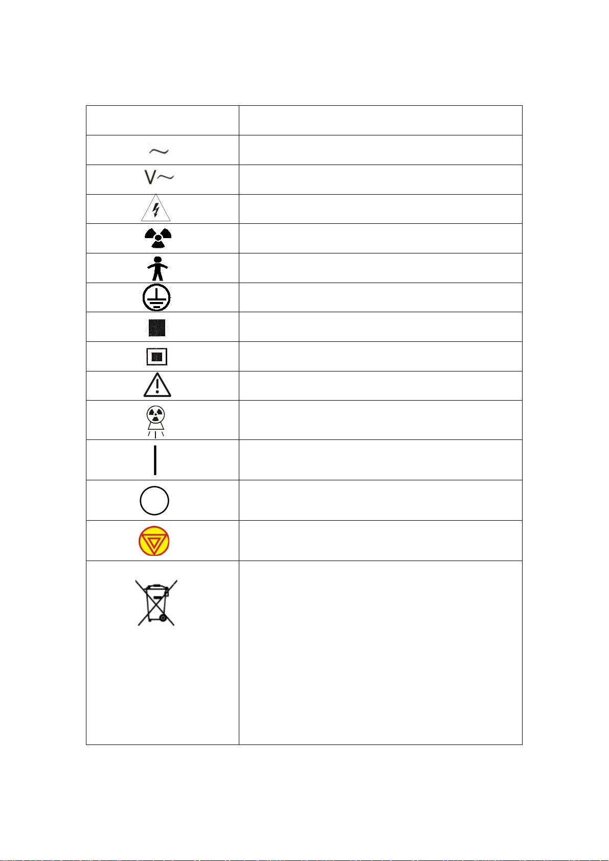
Safety symbols
Symbol Description
Attention, consult accompanying documents.
Alternating current.
AC power.
Dangerous voltage.
Ionizing radiation.
Type B equipment.
Ground.
Large focus.
Small focus.
X-ray radiate.
Power On.
Power Off.
Emergency Switch.
This symbol indicates that the waste of electrical
and electronic equipment must not be disposed as
unsorted municipal waste and must be collected
separately. Please contact an authorized
representative of the manufacturer or an authorized
waste management company for information
concerning the decommissioning of your equipment.
ii
Page 3

Limited condition for transportation and storage:
1. Environment temperature:-20~+45℃
2. Relative humidity range:10~80% no condensation
3. Range of atmospheric pressure :700~1060hPa
4. Conforming to the standard YY91099-2007
iii
Page 4

Please contact your supplier of the manufacturer for repairs and maintenance if there is
any trouble of machine.
Manufacturer: Shenzhen Landwind Industry Co.,Ltd.
Address: 4F,Block E, Bijing Bldg.81, jingtian Road, Futian District, Shenzhen China
Call center: 400-700-3788
iv
Page 5

Contents
Hazard Messages ....................................................................................................... i
Safety classification of the equipment ......................................................................... i
Safety symbols ............................................................................................................ ii
Chapter I General ........................................................................................................ 5
1.1 Installation environment conditions: ..................................................................... 5
1.2 Space requirements ............................................................................................ 5
1.3 Power requirements ............................................................................................. 6
Chapter II composition of the product and parameters ............................................... 7
2.1 Product composition structure .............................................................................. 7
2.1.1 Radiography table control system .............................................................. 7
2.1.2 High-Frequency and High-Voltage mainframe system ............................... 7
2.2 Main properties and technical parameters .......................................................... 8
Chapter Ⅲ Working principle .................................................................................... 10
3.1 Block diagram of circuit principle ........................................................................ 10
3.2 Principle of power and switch ............................................................................. 10
3.3 Generation and control principle ......................................................................... 11
3.4 X-ray tube filament heating principle ................................................................... 11
3.5 Start up and protection principles of rotary anode .............................................. 12
3.6 kV, mA and s interlock protection principle of capacity constraint ...................... 12
3.7 Control principle of radiography duration ........................................................... 12
3.8 Control principle of common radiography ........................................................... 12
1
Page 6

3.9 Control principle of Bucky diaphragm radiography ............................................. 13
3.10 Fault detection principle ................................................................................... 14
Chapter Ⅳ Installation Instructions ........................................................................... 15
4.1 Unpacking inspection ......................................................................................... 15
4.2 Installation Flow ................................................................................................. 15
4.3 Mechanical Installation ....................................................................................... 15
4.4 Cable connection ............................................................................................... 23
4.4.1 Connection between generator and tube ................................................. 23
4.4.2 Connection of common radiography machine Bucky diaphragm ............. 25
4.4.3 Connection of vertical radiography stand ................................................. 26
4.4.4 Other connections .................................................................................... 27
4.4.5 Connection of generator mainframe and console .................................... 27
4.4.6 Connection of generator mainframe and power ....................................... 28
Chapter Ⅴ Calibration instructions ................................................................................ 32
5.1 Collimator calibration ......................................................................................... 32
5.2 Chest plane center alignment ............................................................................ 32
5.3 Tube calibration .................................................................................................. 32
5.4 Generator Calibration ......................................................................................... 32
5.4.1 Preparation before debugging.................................................................. 32
5.4.2 Test of rotary anode ................................................................................. 34
5.4.3 Calibration of tube voltage ....................................................................... 34
5.4.4 Calibration of tube current ........................................................................ 35
2
Page 7

5.4.5 Test Bucky diaphragm .............................................................................. 37
5.5 Commissioning .................................................................................................. 37
Chapter Ⅵ Maintenance ................................................................................................ 38
6.1 Operator Maintenance ....................................................................................... 38
6.2 Overhaul ............................................................................................................ 39
Chapter Ⅶ Troubleshooting ........................................................................................... 40
7.1 Error Code ......................................................................................................... 40
7.2 Key point in fault diagnosis ................................................................................ 41
7.2.1 Console .................................................................................................... 42
7.2.2 Interface unit(PCB 21001E) ................................................................ 42
7.2.3 Mainframe control unit (PCB 21002C) ................................................ 44
7.2.4 Pulse width modulation unit (PCB 21003C) ............................................. 45
7.2.5 Auxiliary power ......................................................................................... 47
7.2.6 ±12V auxiliary power (PCB 21021) .......................................................... 47
Chapter Ⅷ Technical description ................................................................................... 48
Attached schedule—spare parts ..................................................................................... 50
3
Page 8

Blank Page
4
Page 9

Chapter I General
1.1 Installation environment conditions:
1. Environment temperature:10~+30℃
2. Relative humidity range:45~75% no condensation
3. Range of atmospheric pressure :860~1060hPa
1.2 Space requirements
Checking room area: 4.2×3.8 ㎡ Standard;
Operation room area: 4.2×2.0 ㎡ Standard;
Medical X-Ray Radiography System
Service
Height of room: ≥3.0m;
Height of the door: ≥2.3m;
Width of the door: ≥1.4m;
The brick wall of the examination room should has a thickness of 370mm
(equate with 2mm Al), the thickness of the concrete wall should be more
than 200mm;
The lead glass thickness between examination room and operating room
should be more than 1.5mm lead equivalent, and field of vision should not
less than 0.25 ㎡,with height of 1200mm from ground;
Roof is 1.0mm lead equivalent.
If the room is at the bottom of building, protection measure for the ceiling is
needed; the protection should not less than 2mm Al equivalent. If the room is
not at the bottom, there is not only the ceiling but ground is needed X-ray
protection, which also requires 2mmAl equivalent. While the room is at top, it
just needed to make a protection for ground.
5
Page 10

Medical X-Ray Radiography System
Service
If the room is at the bottom (either cottage or building), the glass of the
examination room should use lead glass with 1mmAl equivalent or 240mm
brick wall;
It is advised that the room should has a smooth cement floor or ceramic tiles
on the ground, if it is a wood floor, the installed location on the ground must
be reinforced, and the ground under the installation of the base location
demand of 100mm deep cement, and no less than 800 kg / ㎡ bearing.
1.3 Power requirements
1) Three-phase AC380V, 100A power switch, independent earthing line and N
line.
Voltage fluctuant range:≤10%;
Power:≥50kW;
Inherent impedance:≤0.3Ω;
Earthing impedance:≤4.0Ω;
Power line diameter≥25mm
2
;
2) It is recommend that the user should configure with a 80 kW Regulator if the
power supply is instability.
3) The hospital should be purchased a five-core copper cable with 3×25 mm ²
+2×16 mm ², which about 8.5M long.
4) The power of the device is large, please make sure the local transformer
power and density of use of the equipment before installation.
5) It is required that there must be a hole for line between operating room and
examination room. If the hold is on the ground, it must cover by 2mm Al.
6) Installation work should be carried out in accordance with related rules of
power supply department.
6
Page 11

Medical X-Ray Radiography System
Service
Chapter II composition of the product and parameters
2.1 Product composition structure
Medical X-ray Equipment is mainly composed of high-frequency high-voltage generating
device, tube, collimator, Radiography table and Radiography table control system.
Different configurations and performances are provided according to customer demands.
Mechanical parts of this equipment are composed of Column and Radiography table.
Integrated design of column and bed body is used in this Equipment, where the bed body
is fixed to the ground via screws, and the column is fixed onto the bed body via screws,
with horizontal and longitudinal movement of column along guide rails by using gear
bearings. X-ray tube components and Collimator are vertically mounted on horizontal
shaft of the column right above the bed body, capable for vertical movement and rotation;
film box is mounted below bed panel, capable for horizontal and longitudinal movement
along guide rails.
Mainframe system consists of high-voltage generator, control console, and X-ray tube.
2.1.1 Radiography table control system
Radiography table control system controls the longitudinal movement of the column,
vertical movement of X-ray source movement, as well as the components radiography
table horizontal movement by the circuit composed of power supply components,
integrated control panel, control panel, as well as sensors, electromagnet brake
components, etc.
Please refer to the Radiography Table for more information.
2.1.2 High-Frequency and High-Voltage mainframe system
The system contains high-voltage generator, control console and mainly provide X-ray
tube with working voltage.
1. Console
Equipped with touchless membrane key and key tone, the console is connected with
generator and other X-ray system.
2. Mainframe
Including high pressure oil tank, HF inverter, medium speed anode rotation controller
7
Page 12
Medical X-Ray Radiography System
Service
(standard configuration), real-time controller and adaptor.
2.2 Main properties and technical parameters
Note: According to customer requirements and configurations, the equipment
may have different performances and main technical parameters, as per the
actual configuration:
Radiography
table
Generator
Grid
Tube
bed movement
range
Longitudinal ≥950mm
Transverse ≥220mm
Size of tabletop 2100mm×760mm
Height 700 mm
Movement of column and Bucky diaphragm
synchronously and manually
move
Film size 5″×7″ - 14"×17"
X-ray tube assembly vertical movement
range
X-ray tube assembly longitudinal
movement range
1100mm
1350mm
Rotation of column ±180°
X-ray tube rotates around x ray tube
support frame center
±90°
Voltage 380V AC
Power supply
Frequency 50Hz
Nominal output power 50kW
Radiography
Tube voltage adjustment
range
Tube current adjustment
range
Load time adjustment
range
40kV - 150kV
32mA - 630mA
0.003s - 6s
Size 15"×18"
Grid ratio 10:1
Line density 103
Focal distance 100cm/180cm
Maximum
Anode heat
150kHU
units
Tube Voltage 150kV
Maximum
power of tube
19kW/50kW
8
Page 13

Collimator
Medical X-Ray Radiography System
Target material tungsten rhenium molybdenum (RTM)
Target angle 12°
Focal 0.6/1.2mm
Anode rotating
speed (50Hz)
Inherent
filtration
2800 rpm /min
Minimum 1.2mm AL. Equivalent
Lamp timer 30s
Operation
mode
Manual
Service
9
Page 14
Medical X-Ray Radiography System
Service
Chapter Ⅲ Working principle
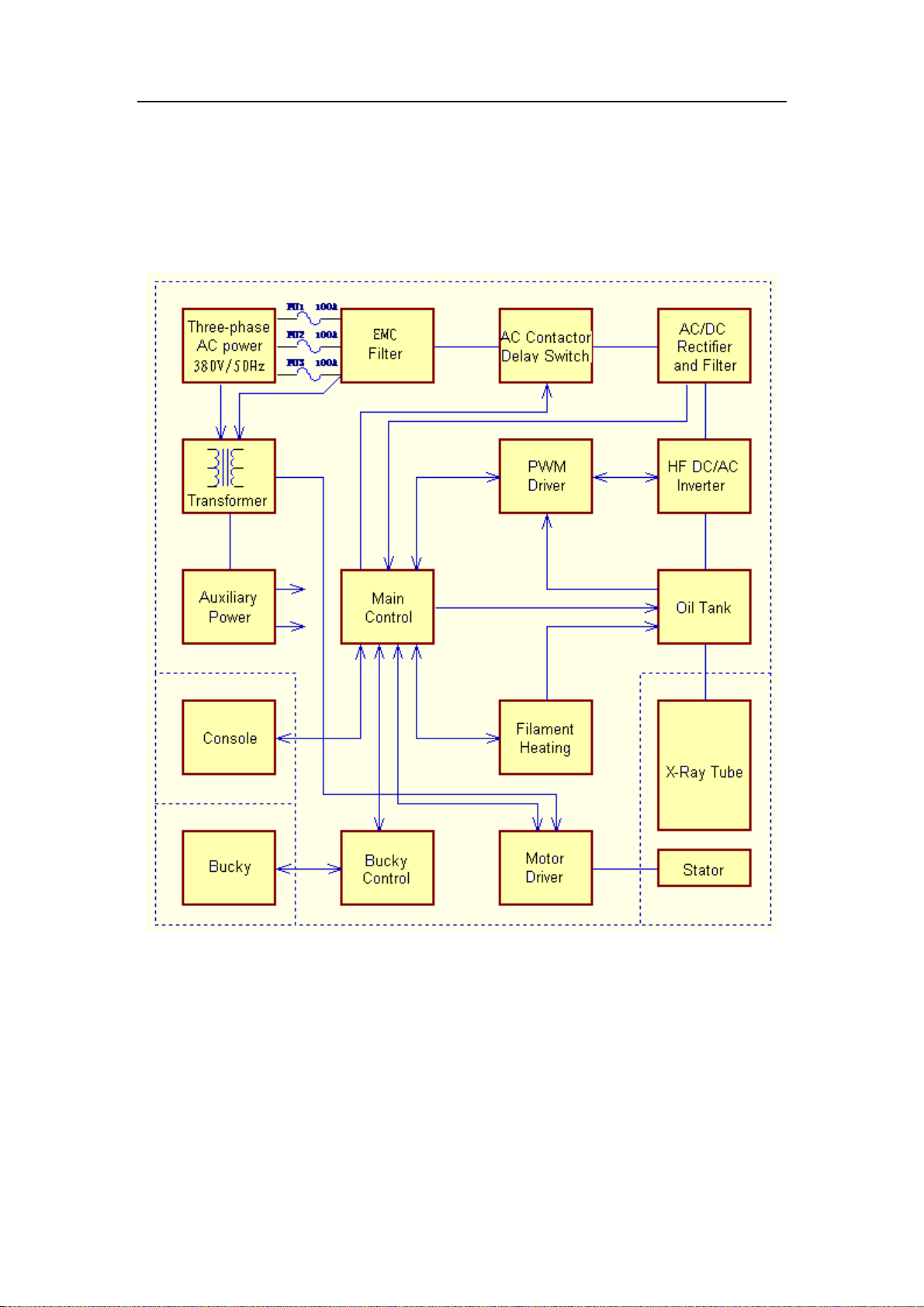
3.1 Block diagram of circuit principle
Figure 3-1 Block diagram of circuit principle
3.2 Principle of power and switch
Three-phase 380V power connects to the mainframe via L1, L2, L3 and N of wiring
terminal X1, and is supplied to the inverter passing through fuse, filter, AC contact, rectifier
module and filter unit. Another line of L3 phase fees to power transformer supplying power
10
Page 15

Medical X-Ray Radiography System
Service
to the auxiliary power supply, which outputs +12V and -12V power to console and
mainframe and auxiliary power to the driving circuit for filament heating. After energization,
the system is shutdown. When "On" key on the console is pressed, the console send start
orders to the mainframe which then changes connector unit terminal X3-8 (power control
terminal) to high level after receipt of the order, the soft charging pulls in the AC contact K2,
voltages from L1, L2, L3 phases perform soft charging to filter unit capacitor through soft
charging resistance R1, R2 R3 and rectifier module. The charging voltage is monitored
and detected by connector unit X4-1 (cold terminal) and X4-2 (hot terminal), when the
voltage exceeds 420Vdc, main AC contact K1 is pulled in, voltages from L1, L2 and L3 is
sent to the inverter through main AC contact K1, rectifier module V1 and filter unit, and
then the main power supply circuit is energized. The machine is ready for start, X3-7
(power status terminal) is at high level, the mainframe control unit sends normal start
signal to the console after receipt of ready-for-start signal, the whole machine is standby.
3.3 Generation and control principle
After startup, three-phase AC 380V power is loaded on inverter after rectifying and
wave-filtering; when the console sends exposure order to the mainframe, the inverter acts,
HF square wave output is loaded on high voltage oil tank to generate high DC voltage.
Voltage sampling circuit of high voltage oil tank feedbacks sampling signals to pulse width
modulation unit, which generates real-control pulse width modulation signal to regulate
high voltage and consequently stabilizes high DC voltage.
Terminal “+kV FB” of generator oil tank top cover is feedback terminal of positive high
voltage, which outputs 1V equal to 10kV output at high voltage terminal; "“-kV FB”" is
feedback terminal of negative high voltage, which outputs -1V equal to -10kV output at
high voltage terminal.
3.4 X-ray tube filament heating principle
Generator heats the filament through pulse width modulation AC voltage. Under different
kV and mA combinations, the control procedure sends control signal of filament data
11
Page 16

Medical X-Ray Radiography System
Service
through digital analog converting circuit, this signal controls filament heating inverter to
generate pulse width modulation AC voltage on filament heating inverter. This HF voltage
excite heating of filament.
Note: Filament is in pre-heating status during standby status.
3.5 Start up and protection principles of rotary anode
When the position 1 of hank brake switch is pressed, rotary anode starter terminal X5-4 on
21001E panel is at low level, controlled silicon V76 is energized; rotary anode winding is
energized to start. After 1 S latency, V75 stops, V77 is energized, at this moment, start-up
voltage of rotary anode winding drops from 160V to 40V for normal operation, triode V53
is energized, status terminal X 5-3 is at low level, indicator lamp on the console illuminates
and radiography preparation is completed. When the position 2 of hand brake is pressed
and after radiography, V77 disconnects, and V78 is energized, 80V pulse DC current is
loaded on anode winding till the anode stops rotation (about 10 s). If some faults impair
start up and rotation of rotary anode, the triode V53 stops, V5-3 is at high level, the
console displays fault information code E40 for anode start up fault. In this case,
radiography may not performed even after position 2 of hand brake switch is pressed, and
by this way the protection is achieve.
3.6 kV, mA and s interlock protection principle of capacity constraint
kV, mA and s interlock protection principle of capacity constraint is controlled by
micro-computer control system intelligent module according to tube capacity
characteristics calculation.
3.7 Control principle of radiography duration
Control circuit of radiography duration is digital circuit with double time limit function.
3.8 Control principle of common radiography
When the console is in radiography status, parameters, such as kV, mA, s/mAs values
and Bucky diaphragm are selectable on the console according to radiation condition.
12
Page 17

Medical X-Ray Radiography System
Service
When the position 1 of hand brake is pressed, CPU of main control unit sends the order
after detecting the information, and then the filament heating circuit of 21003C panel
rapidly heat the cathode filament of the X-ray tube, rotary anode driver of 21001E panel
starts up the rotary anode of X-ray tube for operation. When the position 2 of the hand
brake switch is pressed, pulse width modulation circuit of 21003C panel generates pulse
width modulation signal to drive the inverter, which then drives the high voltage oil tank to
generate high voltage which is loaded on the X-ray tube to generate X-ray and to perform
radiography. If the hand brake switch is loosed during radiation, the exposure radiography
will immediately stop.
3.9 Control principle of Bucky diaphragm radiography
a)Bucky diaphragm is vibration type: Table or vertical chest radiography stand Bucky
diaphragm is selectable on the console, when the position 1 of the hand brake switch is
pressed, the rotary anode starts up to heat the filament, and when the position 2 of the
hand brake switch is pressed, control relays of 2100 penal Bucky diaphragm and chest
radiography stand Bucky diaphragm are pulled in, the Bucky diaphragm pickup winding is
energized and starts to work, the pickup grid moves back and forth, after 0.5s latency, the
control relay of table Bucky diaphragm or the control relay of chest radiography stand
Bucky diaphragm disconnects, the radiography exposure begins, after pre-setting
exposure time, the hand brake switch shall be loosed to reset the control circuit to the
status as before.
b)The Bucky diaphragm is power type: table or vertical chest radiography stand Bucky
diaphragm are selectable on the console, when the position 1 of hand brake switch is
pressed, control relay of 21001 E panel table Bucky diaphragm or the control relay of
chest radiography stand Bucky diaphragm pulled in, the Bucky diaphragm motor is
energized and starts to work, the grid is driven and moves back and forth, when the
position 2 of hand brake switch is pressed, radiography exposure begins, after presetting
exposure time, the control relay of table Bucky diaphragm or the control relay of the chest
13
Page 18

Medical X-Ray Radiography System
Service
radiography stand Bucky diaphragm disconnects.
3.10 Fault detection principle
Mainframe control system performs self-inspection during electrification and performs
monitoring to all units during operation of the mainframe, in case of abnormal condition,
the system may suspend in real-time, send fault information to the console and send fault
alert signal.
When the grid has phase voltage lower than 342Vac or loses phase, connector unit
terminal X2-3'' P-S is at low level, the control system may generate power fault information
code "E00" after detecting this low level, the mainframe cut off main power supply.
When the position 1 of hand brake switch is pressed, the control system will monitor
filament heating circuit and anode driving circuit. The filament is heated and temperature
will be increased, if the heating current is over-low or the heating voltage is over-high, the
control system will generate default information of filament unit as "E03". X3-12''FIL CON'
level of filament heating inverter of pulse width modulation unit increases, filament heating
inverter cut off, at the same time, the main power supply disconnects. When the rotary
anode is driven abnormally, level of X2-4 "M-S" of driver A1 increases, the system detects
the signal and generates anode default information "E04", the rotary anode driving stops
and the main power supply is cut off.
During exposure, if the inverter components fails due to over-current or poor connection of
power components caused by discharge in the high voltage circuit. protective circuit of
inverter acts, port voltage of X1_6“OC_A” or X2_6“OC_B” of the converter drops under
4V, and the protective circuit of the pulse width modulation unit acts to cut off the output of
pulse width modulation signal, and then the inverter stops. At this moment, the pulse width
modulation circuit board (PCM 21003C) illuminates fault status LED and outputs low level
to the main control unit, which then suspends and stops exposure, the main power supply
is cut off, and default information "E01" or "E02" are sent to the console, in such a way, the
mainframe hardware and software are protected.
14
Page 19

Medical X-Ray Radiography System
Chapter Ⅳ Installation Instructions
Pre-installation inspection:
Machine room layout meeting requirements;
Connection to corresponding power supply;
Installation of grounding facilities.
Note:
Installation of equipment shall be completed by trained and authorized
persons.
Service
The installer shall allow for easy operation of the equipment and sufficient
space for maintenance during installation.
Check for damage and obvious rain trace on external package.
4.1 Unpacking inspection
After unpacking the box, please check for completion good condition of parts and
accessories per accessory list.
Immediately contact your supplier in case of incompletion or damage of parts.
The accessory list is made based on your purchase contract.
Note: Keep the packing materials for reuse of them in future packing and
delivery.
4.2 Installation Flow
Fixing table→ Table installation→ Column installation→ X-ray tube assembly
installation→ Controller panel installation→ Collimator installation→ Chest unit
installation→ Electric lines connection.
4.3 Mechanical Installation
Step 1: Fixing table components. Move the table to designated position where punch fixed
15
Page 20

Medical X-Ray Radiography System
Service
hole well in advance and fasten it with screws.
Step 2: Install the table panel. Loose screw the hexagonal cylinder head mounting screws
of the limited block, remove the block at one end, and the table panel will be push to the
table components; the pulley on the both side of table components must be slotted into
table panel’s rail at the same time. After installation, slid back and forth to see if it is
smooth, if not, you should adjust the two pulley eccentricity at ends of the components.
Finally, fix back the limit block to the rail.
Caution: This step requires at least two people to operate simultaneity to avoid
personal injury or equipment damage for the panel is heavy.
Table Panel
Limit block
Figure 4-1 Table panel installation
Column pulley installation. First remove the limit block at one end of the rail, and then
push the pulley into the rail gently, and then fix back the limit block to the rail. Glide the
pulley back and forth to see if it can move smoothly, if not, it is necessary to readjust the
eccentric screw on the pulley to adjust the flexibility of pulley.
Note: The cover plate should be taken down before adjusting the eccentric
screw.
Note: The limit block should be installated before adjusting the eccentric
screw.
16
Page 21

Cover plate
Pulley
Medical X-Ray Radiography System
Service
Rail
Figure 4-2 Pulley installation
Eccentric screw
Limit block
Figure 4-3 Eccentric screw and limit block
Step 4: The weights box installation. Foist the weights box into column from top of
column; pay attention to wire rope, four-wheeled of weight box should resist the column’s
four angles.
Note: You should put 6-8 weights into the box to keep the balance of the
column and support.
17
Page 22

Medical X-Ray Radiography System
Service
Note: Check the wire rope which had fixed to the box before installation.
Note: The wire ropes should straighten out before installation, to avoid the wire
is clamped between box and column at the installation process.
Weights Box
Figure 4-4 Weights box installation
Step 5: install the wire rope wheel at the top of the column and arrangement the wire rope
to bridge over the wheel, and then fix the wheel with screws.
18
Page 23

Medical X-Ray Radiography System
Service
Column
Wheel
Figure 4-5 Wheel installation
Step 6: Hold up the column and vertically put on the pulley, fix it with six cylinder
hexagonal head screws.
Column
Screws
Figure 4-6 Column installation
19
Page 24

Medical X-Ray Radiography System
Service
Caution: the tube support will rise after the weights have been laid; it needs one
people to draw the tube support to avoid possible equipment damage.
Caution: As the column is heavy, this step needs at least four people to
cooperate with the installation.
Warning: After this step, the quantity of the weights in the box should be adjust
in time, to avoid the damage due to the drop down of the support.
Step 6: Put the X-ray tube on the support and fix it with four screws. Take attention to the
direction of the tube, ensure the faucet for high-voltage cable must forward to the column
as show as following figure. Then adjust the tube at horizontal state, finally screw down
the taper dowel.
Caution: For the weights reasons, there is a person to need to pull down the
tube support and keep at a appropriate location, and then another person
install the tube at X-ray tube installation; and then release the support slowly to
the top.
Support
20
Figure 4-7 X-ray tube installations
Page 25

Medical X-Ray Radiography System
Service
Adjust taper pin
Screws M5X16
Figure 4-8 Fix the X-ray tube
Step 7: Collimator installation. Slightly loosened four cross screws of collimator, poke out
two fixing brackets; install collimator on the controller panel, then poke in the brackets to
buckle flange, fix four cross screws on collimator with spanner. Finally connect the wires of
collimator.
Figure 4-9 Collimator installation
Caution: When fix the screws of the collimator; the collimator should be
supported to prevent the damage due to drop down.
Step 8: Control panel installation. Cover the control panel support at the tube support and
fix with six screws.
21
Page 26

Medical X-Ray Radiography System
Service
Control panel support
Figure 4-10 Control panel support installation
Step 9: Install the panel to the support and fix with six screws.
Figure 4-11 Control panel installation
22
Fixed screws
Figure 4-12 Control panel installation
Page 27

Medical X-Ray Radiography System
Service
Step 10: Connect the lines between X-ray tube and radiography table.
Step 11: Install the cover and shield of column.
Step 12: Chest unit installation. Rotate the tube with 90°and measure the distance
between it and two vertex of chest unit film box by using tapeline,the discrepancy should
not more than 2mm. Finally fix the chest unit to ground with four bolts.
4.4 Cable connection
4.4.1 Connection between generator and tube
Anode and cathode cables shall be arranged according to space arrangement (length of
cable).
1. Connection of high voltage cable
Caution:
Terminal plug of high voltage cable is subject to damage and shall be
careful during use.
These terminal plug shall be kept straight, and dowels shall be open (in
parallel edge to edge ).
1)Accessories of each terminal plug shall be installed in accordance with instruction of
cable manufacturer.
2)High voltage port of X-ray tube shall be kept clean. The whole surface of high voltage
plug to be connected to X-ray tube including metal pin shall be coated a layer of silicon
grease. Anode cable and cathode cable shall be carefully connected to corresponding
X-ray tube input terminal. All connections shall be correct, anode and cathode directions
shall be correct, Cable nuts shall be tightened.
3)The high voltage cable plug to be connected to the generator shall be coated a layer of
silicone grease. The anode and cathode cable which have been connected with the X-ray
23
Page 28

Medical X-Ray Radiography System
Service
tube shall be connected to corresponding generator plug. All connections shall be correct,
anode and cathode directions are correct. Cable nuts shall be tightened.
2. Wiring of rotary anode motor cable
Function of X6 terminal of connector unit circuit board (PCB 21001E) is indicated in figure
4-13. Cable of rotary anode shall be correctly connected to X6 terminal of connector unit
circuit board (PCB 21001E) of generator mainframe, As indicated in figure 4-14. The
machine may drive middle speed tube (2800r/min), driving voltage setting of rotary anode
is: start-up voltage of 160Vac, operation voltage of 40Vac and braking voltage of 80Vac,
for adjustment, it is only required to shift one end of each power line (16#, yellow),
operation power line (17#, red) and braking power line (18#, green) from terminal block
(PCB 21008) to required voltage leading-out terminal on the terminal block. Selectable
voltages and positions are indicated in figure 4-15.
Figure 4-13 Port terminal X 6 (PCB 21001E)
1 Working winding driving output port of rotary
anode (2)
2 Starting winding driving output port of rotary
anode (1)
3 Driving output common port of rotary anode
(0)
4 Power null line (N)
5 Null(NC)
6 Working power input port of rotary anode
(RUN)
7 Starting power input port of rotary anode(ST)
8 Braking power input port of rotary anode
(BRAKE)
24
Page 29

Medical X-Ray Radiography System
Figure 4-14 Installation diagram of rotary motor
Service
Figure 4-15 Terminal board (PCB 21008B)
Note: as indicated in the figure, incoming line end of live line goes out from live
line leading-out terminal via fuse F14, two incoming lines and outgoing lines
are short connected respectively via PCB short-circuit copper foil; two null line
s are short connected via PCB short-circuit copper foil.
4.4.2 Connection of common radiography machine Bucky diaphragm
Function of X1 terminal of interface unit circuit board (PCB 21001E) is indicated in figure
4-16.
25
Page 30

Medical X-Ray Radiography System
Service
Vibration winding of common radiography machine Bucky diaphragm or cold end
connection wire of actuating motor stator shall be connected to low level end (such as null
line ) of Bucky diaphragm driving power, the hot end connector shall be connected to the
rd
terminal of X1 terminal of interface unit circuit board (PCB 21001E), and the high level
3
end (such as live line) of Bucky diaphragm driving power shall be connected to the 4
th
terminal of X1 terminal of interface unit circuit board (PCB 21001E). If the Bucky
diaphragm driving power needs 110Vac, which can be lead out from terminal block
(PCB21008) as indicated in figure 4-15. Electrical connection of common radiography
machine Bucky diaphragm finally completes after cable laying.
Note: Bucky diaphragm driving power high level connector shall be connected
via fuse.
Figure 4-16 Interface terminal X1 (PCB 21001D)
1 Standby 5 Driving control port of Bucky diaphragm 2
2 Driving port of AC contact K1
3 Driving control port of Bucky diaphragm 1 7 Driving port of AC contact K3
4 Driving power port (such as null line ) of
Bucky diaphragm 1
6 Driving power port (such as null line ) of
Bucky diaphragm 2
8 Driving power port (null line ) of AC contact
4.4.3 Connection of vertical radiography stand
Vibration winding of Bucky diaphragm or cold end connection wire of actuating motor
rotator shall be connected to low level end (such as null line) of Bucky diaphragm driving
th
power, hot end connector shall be connected to 5
26
terminal of X1 terminal of interface unit
Page 31

Medical X-Ray Radiography System
Service
circuit board (PCB 21001E), high level end of Bucky diaphragm driving power (such as
th
live line) shall be connected to the 6
terminal of X1 terminal of interface unit circuit board
(PCB 21001E). Electrical connection of common radiography machine Bucky diaphragm
finally completes after cable laying.
Note: Bucky diaphragm driving power high level connector shall be connected
via fuse.
4.4.4 Other connections
If radiography machine power supply is special, such as 110V/50Hz or 24V/50Hz, the
power can be lead out from circuit board (PCB 21008), as indicated in figure 4.
Note: Power capacity is limited as:110V×2A=220VA,24V×8A=192VA。
If localization light of collimator requires additional 12Vac power, which can be lead out
from terminal 1st and 2
nd
of terminal X4 of circuit board (PCB 21008B).
Note: Power capacity is limited as: 12×9=108VA。
4.4.5 Connection of generator mainframe and console
The mainframe adopts flexible RS422/RS232 communication interface technology. If the
console adopts RS 422, the core of RS422 shall be installed on D15 integrated block plug
beside the communication socket before connection; if the console adopts RS232, the
RS422 core shall be removed, and the core of RS232 shall be installed on D14 integrated
block plug beside the communication socket
1. The pin plug of accessory communication cable shall be inserted in port X2 of
mainframe control unit circuit board (PCB21002C), plug screws shall be tightened, as
indicated in figure 4-17, and communication cable shall be properly laid.
2. Another end of communication cable shall be plugged into pin bed of console, as
indicated in figure 4-16. Plug screw shall be tightened.
27
Page 32

Medical X-Ray Radiography System
Service
Figure 4-17 Connection diagram of communication cable
4.4.6 Connection of generator mainframe and power
1. Before power cable connection, user shall properly prepare electrical cabinet as
indicated in figure 4-18 or electrical cabinet with equivalent function and emergency
switch. Power cable shall be high quality multi-strand copper core insulation cable.
When the three-phase-four-line power cable is used, protective earthing cable shall be
yellow-green double color insulation high quality copper core multi-strand cable with
2
cross section not less than 10mm
.
2. Function of generator power interface terminal is indicated in figure 4-19.
28
Page 33

Medical X-Ray Radiography System
Service
Figure 4-18 Arrangement diagram of X-ray room power
Figure 4-19 Power interface terminal X1
1 Power supply L1 phase interface (L1)
2 Power supply L1 phase interface (L2)
4 Power supply null line
interface (N)
5 Protective earthing port (PE)
3 Power supply L1 phase interface (L3)
Followings shall be noted during connection:
a) It is proposed to install an emergency switch beside the console.
29
Page 34

Medical X-Ray Radiography System
Service
b) Circuit breaker power of electrical cabinet is off.
c) The cable shall be cut off a proper length, and insulations on both ends of the cable
shall be removed, and wire lug shall be connected through pressure welding.
d) Power phase lines of L1, L2, L3 and null line (N) shall be connected to corresponding
port on terminal block of power interface terminal X1, and protective earth shall be
connected to PE terminal of power interface terminal X1.
e) Power line shall be laid properly and connected to corresponding interface of electrical
cabinet.
f) Make sure that the emergency switch has been correctly connected to the electrical
cabinet; when the emergency switch is pressed, generator power can be cut off.
g) It is proposed to take out fuse tubes of three fuses of F1, F2 and F3 from generator
mainframe, and then they shall be directly measured by
ends.
multimeter on X1 of five power
Note: contact resistance of protective earth line shall meet standard.
Figure 4-20 Wiring diagram of X1 terminal
Warning: the generator keeps connection with the power line, unless the circuit
30
Page 35

Medical X-Ray Radiography System
Service
breaker installed on the electrical cabinet is closed, or the safety switch on the
generator is closed, the power will keep on.
Note:
Although the console is closed, the internal auxiliary power supply and
control circuit of the generator still connects with the po wer line. Make sure
that the system shall have been fully disconnected with the grid before
repair and maintenance.
X1-PE is protective earth port. Protective earth connector shall be copper
2
line with cross section not less than 6mm
;The earth line shall be properly
connected with special earth line.
31
Page 36

Medical X-Ray Radiography System
Service
Chapter Ⅴ Calibration instructions
5.1 Collimator calibration
Manually operate the two knobs on collimator panel to calibrate X-ray beam range. At
1.
1m position from focus, on the plane vertical to bed, selectable minimum X-ray beam
size should be less than 15 × 15 mm.
2. Turn on indicate lamp switch, make up/down movement of tube focus, change SID,
and check for light source center line deviation distance ≤ 10mm. If it exceeds the
range, check dolly installation status, loose tube anti-turn screws, and readjust tube
angle.
Please refer to Collimator for more information.
5.2 Chest plane center alignment
Paste a small piece of lens onto film box center, and then weaken collimator light,
estimate the lens area size, observe the position of reflected light; if the reflected light hit
the central position of collimator, it means center alignment of chest plane has been
achieved.
5.3 Tube calibration
1. Shut down mainframe power supply, connect high-voltage cable to host generator,
start up the machine and calibrate tube.
2. Turn tube to “0” position, and SID to “100”, and then put film box in film box plate; turn
on light source of light collimator, place a marker on bed cross center and then, make
exposal to check for deviation of X-ray source from film box center, which should be ≤
10mm. If it exceeds the range, readjust light source of light collimator and make
another exposal for further check.
5.4 Generator Calibration
5.4.1 Preparation before debugging
1. Debugging or detection instrument shall be as follows:
1)Storage oscillograph Tektronix TDS210 or similar products
2)Multimeter
32
Page 37

Medical X-Ray Radiography System
Service
3)Digital milliammeter (optional)
4)Digital milliampere-second meter (optional)
5)Voltage box (optional)
6)X-ray dose tester (optional)
2. Before energization, all power terminals and connectors shall be scrutinized to
eliminate short-circuit or open-circuit and etc, to ensure correct and firm connection.
1) Protective earth shall be specially checked for reliable connection, and shield of high
voltage cable shall be specially checked for reliable connection to the ground.
2) High voltage socket of oil tank shall be checked for reliable connection to tube anode
and cathode.
3) If tube current is directly tested, two ends of mA detecting point on the oil tank shall be
check to make sure reliable connection with mA detector.
nd
4)Resistance of the 2
of X 5 terminal of pulse width modulator (PCB 21003C) and resistance of 3
(minifocus) against 1
position, and the resistances shall be zero.
5) When resistance of 5
terminal (macro focus end) against 1st terminal (common terminal)
rd
terminal
st
terminal (common terminal) shall be measured by multimeter ohm
th
terminal against 4th terminal of terminal X2 on pulse width
modulator (PCB 21003C) is 4.7kΩ(±0.5kΩ) measured by multimeter, this indicates that
the +kV sampling circuit is normal; When resistance of 6th terminal against 4th terminal
of terminal X2 on pulse width modulator (PCB 21003C) is 4.7kΩ(±0.5kΩ) measured by
multimeter, this indicates that the -kV sampling circuit is normal; When resistance of 1st
terminal against 3rd terminal is 10kΩ(±0.5kΩ), and when the machine is in
fluoroscopy
mode, the
+mA sampling circuit is normal, when resistance of 2
resistance of 1st terminal against 3rd terminal is 200kΩ, this indicates that the
nd
terminal against 4th terminal is 0kΩ,
this indicates that the -mA sampling circuit is normal (-mA has been reliably connected
with earth end).
33
Page 38

Medical X-Ray Radiography System
Service
5.4.2 Test of rotary anode
This test requires two operators, one operates console, the other operator observes
rotating speed of anode of X-ray tube. When the position 1 of hand brake switch is
pressed, rotating speed of anode shall be checked and the start up of anode shall be
normal.
Note: during test, exposure shall be avoided; otherwise, operators approaching
to the X ray tube may suffer X-ray radiation.
5.4.3 Calibration of tube voltage
Before ex-factory, KV value of the machine has been correctly calibrated, in general,
recalibration is not necessary, however, if necessary, following steps shall be followed for
recalibration:
1. Protective unit (PCB 2100108A)TP1 is test point of +kV value, TP3 is test point of -kV
value and V4 cathode is earth clamping end.
2. At test point of kV value, ratio of voltage value to kV is 1V:10kV, hot end of
storage oscilloscope
probe 1 is clamped to test point of +kV value, cold end is clamped to
digital
measuring earth, hot end of probe 2 is clamped to test point of -kV value and cold end is
clamped to measuring earth. (or apply volt box or other measuring instrument) .
3. Voltage of 21002 C panel TP2 shall be 3.20V (±0.05V) measured, otherwise 21002 B
potentiometer RW3 shall be finely adjusted; Voltage of 21002 C panel TP3 shall be
0.57V(±0.05V) measured, otherwise potentiometer RW2 shall be finely adjusted;
4. Parameter selection of calibration point: minifocus, 50mA,100ms,40kV (note: voltage
on one side is half of this kV value.)
5. Exposure, adjusted pulse width modulator 21003C potentiometer RW1 (adjustment +
kV value), RW2 (adjustment -kV value) (kV value increases in clockwise adjustment and
reduces in counterclockwise adjustment), and then exposure and fine adjustment shall be
34
Page 39

Medical X-Ray Radiography System
repeated till correct calibration is achieved (error less than 5%).
Service
Figure 5-1 waveform of output voltage
6. Voltage calibration of the tube has been completed.
5.4.4 Calibration of tube current
Calibration of tube current is realized by setting the tube current through changing
corresponding byte in filament current data ROM. Data corresponding to each setting
value varies with different parameters of tube and high voltage cable. Even in a same tube,
after a period of time, the setting current may deviate from the actual tube current,
therefore, the tube current shall be subject to preliminary calibration after installation;
during use, regular calibration shall be performed at 6 month or shorter interval. Calibrated
data are stored in nonvolatile memory chip, which locates on PCB of mainframe control
unit.
When tube current is directly measured, current measurer has special requirement to
shortest sampling time for measurement, such as continuous measurement sampling time
35
Page 40

Medical X-Ray Radiography System
Service
of milliampere-second meter is longer than 70ms, continuous measurement sampling time
of current position of common digital multi-meter is longer than 500ms, to shorten time for
calibration and reduce X-ray radiation hazard to calibrators, it is proposed to adopt current
resistance sampling for indirect measurement, which adopts
measure voltages on both ends of sampling resistance.
storage oscillograph to
During tube current calibration, the storage oscillograph is used as measuring tool,
Tektronix TDS210 storage oscillograph is proposed to use, test point of tube current is at
R27 (has been lead out with by resistance) of protective panel (PCB 200108A). At this
point, ratio of voltage to tube current is 1V:100mA (in
to tube current is 200mV:1mA
); the cold end of storage oscillograph probe shall be clamped
fluoroscopy status, the ratio of voltage
at V4 cathode (GND) on panel, and hot end shall be clamped at R27 (lead out with
resistance).
Radiography tube current shall be calibrated as per following steps:
1)Press “S/mAs” key till two "Di" sound, ant then release the key, then the system is in
maintenance status.
2)Press radiography kV increase/decrease selective key to display "2" in radiography kV
display screen, at this moment, modification of password unit is selectable.
3 ) Press radiography mA increase/decrease selective key to display modification
password "88" on radiography mA screen.
4)Press "storage key" to store this value
5)Press "RST" key to return to standby condition.
6)Select focus. such as minifocus
7)Press S/mAs increase/decrease key to set the exposure time to 25ms.
8)Press mA increase/decrease key to preset mA value.
9)Press kV increase/decrease key to set kV value to 45kV.
36
Page 41

Medical X-Ray Radiography System
Service
10) Press "S/mAs" key till four "Di" sound, S/mAs display screen indicates "P"; release the
key.
11) Press S/mAs increase/decrease key to display data to be input in S/mAs display
screen, such as "P 80".
12) Press "storage key" to store this value.
13) Perform exposure action under this condition.
14) Read storage oscillograph recorded value. if recorded value is higher than setting
value, value in S/mAs display screen shall be reduced, on the contrary, the value shall be
increased.
15) Repeat 11)--14) steps till record value of oscillograph is in line with the setting value,
and then the calibration of combined parameter of kV value and mA value has completed.
16) Increase kV value by 10kV, repeat 11)--15) steps to calibrate this combined parameter.
17) Repeat step (16) till mA calibration completes.
18) Repeat steps 6) --17) to calibrate another mA.
5.4.5 Test Bucky diaphragm
If ready key is pressed in safety condition, the electric Bucky diaphragm shall operate; if
exposure key is pressed, the vibrator Bucky diaphragm shall vibrate. When exposure
finishes, the Bucky diaphragm shall stop.
5.5 Commissioning
After debugging and in normal operation condition, test card or water bag maybe used as
test piece for radiography to determine normality of the machine.
37
Page 42

Medical X-Ray Radiography System
Service
Chapter Ⅵ Maintenance
In order to ensure the continued safe operation, X-ray machine should carry out regular
maintenance. There are two aspects of the maintenance, one is by the user or operator
maintenance, and the other is by qualified service personnel. The manufacturer bear to
provide at least 5 years supply of spare parts after the machine manufacturers.
6.1 Operator Maintenance
1. After one-week operation, user may spray Pledge on equipment surface, and then
wipe the surface with dry gauze or tower.
2. After each operation, user shall thoroughly wipe the table panel surface with
gauze dipping with medicinal alcohol.
Pay attention to the following information for maintenance by users:
Caution: Do not remove the casing or internal elements in the cabinet and
console. Damage to personnel or the machine caused by ignoring this attention
is no responsibility of the manufacturer.
1. When the x-ray generator is working, do not clean any part of it. Do cleaning after the
generator is shut down and the power is turned off.
2. Clean the machine frequently, esp. when there is corrosive matter. Spray inorganic
detergent on a piece of rag and use the rag to clean the machine casing. Do not use
vacuums or organic solvents for cleaning.
3. Keep the machine room tidy, dry and airy. The machine shuns heat and the sun.
4. Replace the dewatering filler vaseline in HT connectors periodically. For connectors
used for HT generator components the replacement is done once less than a year; for
connectors used for x-ray tube components, the replacement is done once less than half
year. Intensify examination and updating during the summer or when there is heavy work.
38
Page 43

Medical X-Ray Radiography System
Service
5. Pay attention to the condition of power supply. Check if its internal resistance (or
voltage drop) has changed. Maek efforts to realize the requirements for the power supply
of the machine.
6. Check the grounding device frequently to make sure all parts are safely and reliably
grounded.
6.2 Overhaul
Note: This step shall be performed only by trained service personnel.
1. User shall regularly check dust inside through front and back covers after half or
one year of operation, as the case may be. Check shall focus on various switches
and contacts for their electrolytic corrosion and uncleanness, which shall be wipe
out with gauze dipping with medicinal alcohol, switches and contacts suffering
serious corrosion or pollution shall be replaced. In addition, components and
wiring connectors shall be checked for loose and displacement, tighten them, if
required.
2. During operation, power voltage shall be maintained in normal level. In the event
of occurrence of over-high, over-low, surge voltage and other abnormalities, the
operation shall be suspended till the cause has been found and trouble-shooting
measures has been taken accordingly.
3. All knobs and keys of the controller shall be gently operated; overexertion shall be
avoided to prevent dislocation, damage or poor contact, even breakage.
39
Page 44

Medical X-Ray Radiography System
Service
Chapter Ⅶ Troubleshooting
7.1 Error Code
The generator is capable of self-diagnosis. It can give signals to report big problems,
helping with repair a lot. For trouble-shooting, normally, check the power supply system
first and then the auxiliary power supply of the generator.
When the system goes wrong, the KV screen on the console will display the
corresponding error code as the figure 7-1 shows:
Figure 7-1 Error code illustration
Fig. Error code display
Error
code
Where and what is the problem? Trouble-shooting
E00 Abnormal power or fault of input circuit
Overcurrent or fault of inverter
E01
discharge of BR1. X-ray tubes or HT
parts and lead to over-loading.
Overcurrent or fault of the inverter
E02
discharge of BR2. X-ray tubes or HT
parts and lead to over-loading.
E03
E04
Failure of cathode heating or the fault
of heating driver circuit
Failure of anode heating or the fault of
anode heating driver circuit
Check normality of AC power and
replace the circuit board of the
interface unit.
Check HT circuits and the inverter
and replace faulty parts.
Check HT circuits and the bulb tube
and filament heating circuit and
replace faulty parts.
Check anode motor circuits and
anode drivers and replace faulty
parts.
40
Page 45

E05 The machine fails to start.
E06 The machine fails to shutdown.
E07 Self-diagnosis fails.
E08 Resetting fail.
Medical X-Ray Radiography System
Service
Cut off all power supply, start the
machine two minutes later. if the
trouble is still there, check the
interface board, communication
cables and the console.
Cut off all power supply, start the
machine two minutes later. if the
trouble is still there, check the
interface board, communication
cables and the console.
E09 The internal radiating port fails.
E10
The protective circuit of the inverter
fails.
E11 The focus switching fails.
E12 The Bucky diaphragm fails
E13 Positive deviation of tube voltage.
E14 Negative deviation of tube voltage.
E15 Positive deviation of tube current
E16 Negative deviation of tube current
E17 Positive deviation of voltage reference.
E18
Negative deviation of voltage
reference
E19 Positive deviation of current reference
E20 Negative deviation of current reference
Controlling system hardware problem;
to be checked. Parts to be replaced.
Check normality of electrical
connection of Bucky diaphragm
Calibrated.
E21 Invalid parameters
E22 Invalid orders
E23 Automatic reset of main system
E24 EEPROM is not initialized Initialized debugging performed.
7.2 Key point in fault diagnosis
In case of system error, fault causes can be diagnosed rapidly through checking test point
41
Page 46

Medical X-Ray Radiography System
Service
and signal indicator of corresponding parts, and trouble-shooting may be performed
quickly to recover normal operation of the system.
7.2.1 Console
After switching the power supply on, the control system is energized and begins to self
inspection. Console luminescent indicators flashes to help repairman to perform
inspection. After self inspection, kV screen displays "OFF" or "E"; "E" indication is normal
since last operation shuts down and losses power abnormally. If the console has no
reaction after switching-on, or "E00" is displayed, this may be caused by abnormal power
supply system, and following inspection steps shall be followed:
a)Is the power supply normal?
b)Is the mainframe cabinet fuse normal?
c)Are L1, L2 and L3 phase powers are normal ?
d)Is auxiliary power ±12V is normal?
e)Is communication cable connected correctly?
f)Fault of console.
When "ON" key of the console is pressed, the system begins soft-start; kV display screen
displays initialization accounting. After soft-start, main power source is connected, the
console shall display normal X-ray radiography parameters.
7.2.2 Interface unit(PCB 21001E)
The interface unit is equipped with LED status indicator and reference voltage precision
potentiometer. Item code and information of LED indicator is as follows:
1. V42--filter unit stored energy status indicator lamp. Illumination of V42 indicates
electrification of capacitor. When charge voltage remained in the capacitor is less than
10V, V42 blacks out. Note! Power shall be off at least 3minutes prior to complete
42
Page 47

Medical X-Ray Radiography System
Service
discharging of the capacitor! Black V42 does not mean complete discharge.
2. V19---On indicator. When "ON" key is pressed, the lamp shall illuminate. If black, the
machine will not start, port X3-7 shall be checked for level. If level is low, connection line
with main control unit (PCB 21002) shall be checked; if level is high, this unit (PCB21001D)
or null line and all phases L1, L2 and L3 shall be checked.
3.V20---Bucky diaphragm 1 Working status indicator. If Bucky diaphragm 1 is selected,
the indicator illuminates during exposure preparation and at the moment of exposure.
4.V20---Bucky diaphragm 2 Working status indicator. If Bucky diaphragm 1 is selected,
the indicator illuminates during exposure preparation and at the moment of exposure.
5.V22----Ready-start status indicator. When the machine is ready for start, the indicator
illuminates, X3-7 is at high level. If black, the machine cannot start up, and the console
displays "E00", in this case, check shall be performed according to potentiometer RW3,
which is pre-charging voltage regulation potentiometer, TP4 point beside is level test
point.
(1)If pre-charging voltage exceeds 380VDC and V22 is black, the console displays
"E00" or continuous counting, this may be caused by modified feature of components of
pre-charging voltage monitoring circuit. Press "OFF" key till LED V42 blacks out, finely
adjust RW3 (level at TP4 point decrease) to set low pre-charging voltage, repeat start-up,
fine adjustment and detection till pre-charging voltage reaches to 380VVDC and AC
contact K1 attracts.
(2)If pre-charging voltage is lower than 380VDC, V22 illuminates, AC contact K1 of main
power supply line attracts, the mainframe starts up, after long run operation in this status,
service life of energy storage filtration capacitor (PCB 21007) will be shorten. Finely adjust
RW3 (level at TP4 point increase) in counter clockwise to increase pre-charging voltage to
380VDC.
6. V45……Rotary anode working signal lamp. During standby, the lamp blacks out.
43
Page 48

Medical X-Ray Radiography System
Service
When the Ready key is pressed, the indicator lamp shall illuminates, otherwise, it
indicates that exposure ready check is not passed, the console displays "E04", in this
case, voltage at port X6_6、X6_7、X6_8 (against X 6-4) shall be checked for normality. If
abnormal, corresponding connection wire and fuse and power transformer T1 on terminal
block (PCB 21008) shall be checked; if normal, voltage at X5-5 port shall be checked for
low level after pressing the exposure Ready button, if low, this connection wire and main
control unit (PCB21002) shall be checked, otherwise, the unit (PCB 21001E) shall be
replaced.
7.2.3 Mainframe control unit (PCB 21002C)
Normal start-up indicates that mainframe micro processer's function and communication
interface are normal. Normality of other I/O interface maybe traced and checked through
observing normality of other units. If it is required to replace mainframe control unit circuit
board, the non- volatile store D1 for storing calibration data on original circuit board shall
be shift to newly replaced circuit board. See figure 7-2.
44
Figure 7-2 Main control unit printed circuit board (PCB 21002C)
Page 49

Medical X-Ray Radiography System
Service
7.2.4 Pulse width modulation unit (PCB 21003C)
The pulse width modulation unit is equipped with 8 LED status indicators and two kV
calibration precision potentiometers.
1. V7----Fluoroscopy/radiography status indicator. The indicator illuminates during
fluoroscopy and blacks out during radiography.
2. V23----inverter BR1 protection test indicator. The indicator illuminates during standby
status, when "ON" key is pressed to reset the machine, the indicator blacks out.
3. V24----inverter BR2 protection test indicator. The indicator illuminates during standby.
When "ON" key is pressed to reset the machine, the indicator blacks out.
4. V35---Inverter BR1 fault indicator. The indicator illuminates during standby. when
"ON" key is pressed to reset the machine, the indicator blacks out. During exposure, if this
indicator is black and exposure is abnormally interrupted, this indicates that inverter BR1
is in overcurrent protection status, the console displays "E01", and repair shall be
performed according to steps as follows:
(1)Press clear key or restart machine, select lowest value of 40kv, lowest mA, 250ms
and perform exposure with this parameter.
(2)If exposure is normal, select 80kV and maintain other parameters unchanged, and
re-exposure.
(3)If exposure is normal, select 120kV and maintain other parameters unchanged, and
re-exposure.
(4)If normal, preliminary judgment may deny the existence of discharge fault in high
voltage circuit
(5)If a same fault (fault "E01") occurs during these three exposures, this indicates that
the machine is subject to serious interference or indicates existence of discharge fault in
high voltage circuit or fault in power circuit, in this case, communication cable, earthing,
45
Page 50

Medical X-Ray Radiography System
Service
high voltage connection (high voltage plug, socket and cable) , tube, inverter, high voltage
oil tank, main control penal and consol shall be checked for normality.
5. V32----Inverter BR2 fault indicator. Ditto perform check.
6. V31--inverter working status signal lamp. The lamp illuminates during standby or
protection; during exposure, the lamp blacks out.
7. V38----filament heating status indicator. The indicator blacks out during standby or
abnormal status; presses Ready key, filament is heated, and this indicator illuminates, if
this indicator is black, this indicates abnormal heating, the console displays error code
"E03", and repair shall be performed as follows:
(1)Is filament heating data normal ?
(2)Is communication flat cable connection among pulse width modulation plate and
main control panel are normal?
(3)Is filament heating auxiliary power normal?
(4)Is filament transformer driving circuit normal?
(5)Is filament normal?
(6)Replace this unit circuit board.
8. V67----focus working indicator. The indicator illuminates during large focus and blacks
out during small focus. When focus selection key is pressed, V67 is in corresponding
working status.
9. Potentiometer functions are as follows:
( 1 ) RW1----+kV adjust potentiometer, turn clockwise to increase +kV, turn
counter-clockwise to reduce +kV.
( 2 ) RW2------kV adjust potentiometer, turn clockwise to increase -kV, turn
counter-clockwise to reduce -kV.
46
Page 51

Medical X-Ray Radiography System
Service
7.2.5 Auxiliary power
In case of fault of filament heating auxiliary power +48V, press of Ready key may display
error code "E03".
7.2.6 ±12V auxiliary power (PCB 21021)
Fault of ±12V auxiliary power may cause no reaction of console or continuous counting
after switch-on, the main power cannot connect.
a) E00 code: indicate failure of start-up. A possible damaged part is interface unit
(21001E) or tube overheating protection.
b) E01/E02 code: indicate overcurrent protection of generator. A possible damaged part
is inverter or tube discharge or grid voltage exceeds power requirement.
c) E03 code: indicate failure of filament heating. Possible damaged part is pulse width
unit (21003C) or poor contact of 48V power or high voltage cable cathode or burn out of
tube filament.
d) E04 code: indicate start failure of tube rotary anode. A possible damaged part is burn
out of interface unit (21001E) or tube rotary anode power fuse or abnormal rotation of tube
rotary anode.
47
Page 52

Medical X-Ray Radiography System
Service
Chapter Ⅷ Technical description
1. Filtration of X-ray tube assembly
Additional filter 1.5mm AI equivalent, total filtration exceeds 2.5mm AI equivalent.
2. Limitation of X-ray equipment radiation beam
Range of X ray radiation beam is adjustable through manual operation of two knobs
on the collimator panel. At 1m away focus and on the plane perpendicular to the
tabletop, selectable minimum size of X ray radiation beam shall be less than 15mm x
15mm.
3. Position of reference axis and distance between focus and image receptor
During normal operation, reference axis of X-ray field is perpendicular to the cassette.
Notch of the cassette clamp shall be aligned with reference light of radiation field if
required during radiography. X-ray source assembly is adjustable continuously; SID
value can be read on scale of the column.
4. Corresponding relationship between X-ray field and image receptor
1) Under the circumstance that the cassette plane is perpendicular to the
reference axis (3° tolerance) , the measurement shall indicate that the sum of
deviations between edges of the receptor and edges of X ray filed shall be
not more than 3% of SID indicator value.
2) Sum of deviations between X and Y axial directions shall be not more than
4% of SID indicator value.
5. Distance between focus and skin
To minimize and rationalize patient’s absorption for radiation, the operator shall
maintain distance between focus and skin as longer as possible.
6. Attenuation of X ray beam
48
Page 53

Medical X-Ray Radiography System
To prevent excessive attenuation of X-ray beam caused by the material inserted
between patient and X film, the tabletop panel adopts medium dense laminated panel.
7. Control of protection area
Radiography machine and console shall be installed separately. During loading,
operator or staffs are not required to approach the patient; the generator mainframe
may carry out following isolated control functions:
1) Selection and control of operation method
2) Selection of loading factors
3) Action of radiation switch
Service
8. Position of focus and tolerance between focus and reference axis
Position of focus and tolerance between focus and reference axis is 55.4±0.37.
49
Page 54

Medical X-Ray Radiography System
Service
Attached schedule—spare parts
1. Wearing parts:
NO. P/N name Standard/type PCS
1 47010003 Fuse
2 47010004 Fuse
3 47010005 Fuse
4 39160007
5 39160009
Fixed three-port
Monistat
Fixed three-port
Monistat
Ф5×20,2A/250VAC
Ф5×20,6A/250VAC
Ф5×20,8A/250VAC
TO-220 package,LM7805
LM78H24,TO-3 package 2
3
1
1
1
6 39100008 IC DIP14,74LS06 3
7 26030011
8 48030055
9 48030035 Reset key-switch
Halogen tungsten lamp
Small-size Emergency
stop switch
24V 100W 1
Ф23.6×40,
Ф16, LAS1-A
Ф23.6×40,
Ф16, LAS1
mounting hole
mounting hole
1
4
2. spare parts:
NO. P/N name Standard/type PCS
1 27030003 Colligation Board LWX-50P Colligation Board 1
2 27030001 Power Supply Board
LWX-50P Power Supply
Board
1
3 27030002 Control Panel LWX-50P Control Panel 1
50
 Loading...