

Page 1

SHENZHEN HI-LINK ELECTRONIC CO.,LTD
Version:V1.0 Issuing date:2017-2-17 copy right@Hi-Link
HLK-RM08S USER MANUAL
Page 2

CONTENTS
1. BRIEF INTRODUCTION
1.1. BASIC PARAMETERS
2. BLOCK DIAGRAM
2.1. TYPICAL APPLICATION
2.2. SPECIFICATIONS
3. ELECTRICAL CHARACTERISTICS
3.1. INPUT VOLTAGE
3.2. RF CHARECTERISTICS
3.2.1. 802.11B 11M
3.2.2. 802.11G 54M
3.2.3. 802.11N MCS7(HT20)
3.2.4. 802.11N_MCS7(HT40)
............................................................................................................................................
....................................................................................................................................
......................................................................................................................................................
........................................................................................................................................
..........................................................................................................................................
................................................................................................................................
..................................................................................................................................
..................................................................................................................................
..............................................................................................................................
..........................................................................................................................
....................................................................................................................
....................................................................................................................
1
1
2
3
4
4
4
5
5
5
6
6
4. PINS DEFINITION
4.1. PINS DIFINITION DIAGRAM
4.2. DEFAULT PINS DIFINITION
5. DIMENSIONS
..................................................................................................................................................
..........................................................................................................................................................
......................................................................................................................
......................................................................................................................
7
7
8
10
Page 3

1
HLK-RM08S
1. Brief Introduction
1.1. Basic parameters
High data processing ability,MCU frequency 580MHz
150M Mbps
Support 802.11b/g/n mode
20/40 channel bandwidth
Support 802.11v
Support AP,STA and AP,STA mixed
Fifth 10/100M adaptive com port
One USB2.0 host interface
Multiple interfaces SPI/SD-XC/eMMC
Rich peripheral interfaces,SPI,I2C,I2S,PCM,UART,JTAG,GPIO
Widely used in IOT
Inbuilt powerful PMU
Support 16 Multiple BSSID
Support multiple encryption WEP64/128, TKIP, AES, WPA, WPA2, WAPI
Support QoS,WMM,WMM-PS
HLK-RM08S based on MT7688KN is a low cost and low power consumption IOT module developed by
Hi-Link.The module has rich interfaces and powerful processor and could be widely used in smart devices and
cloud service applications.
Page 4
2
HLK-RM08S
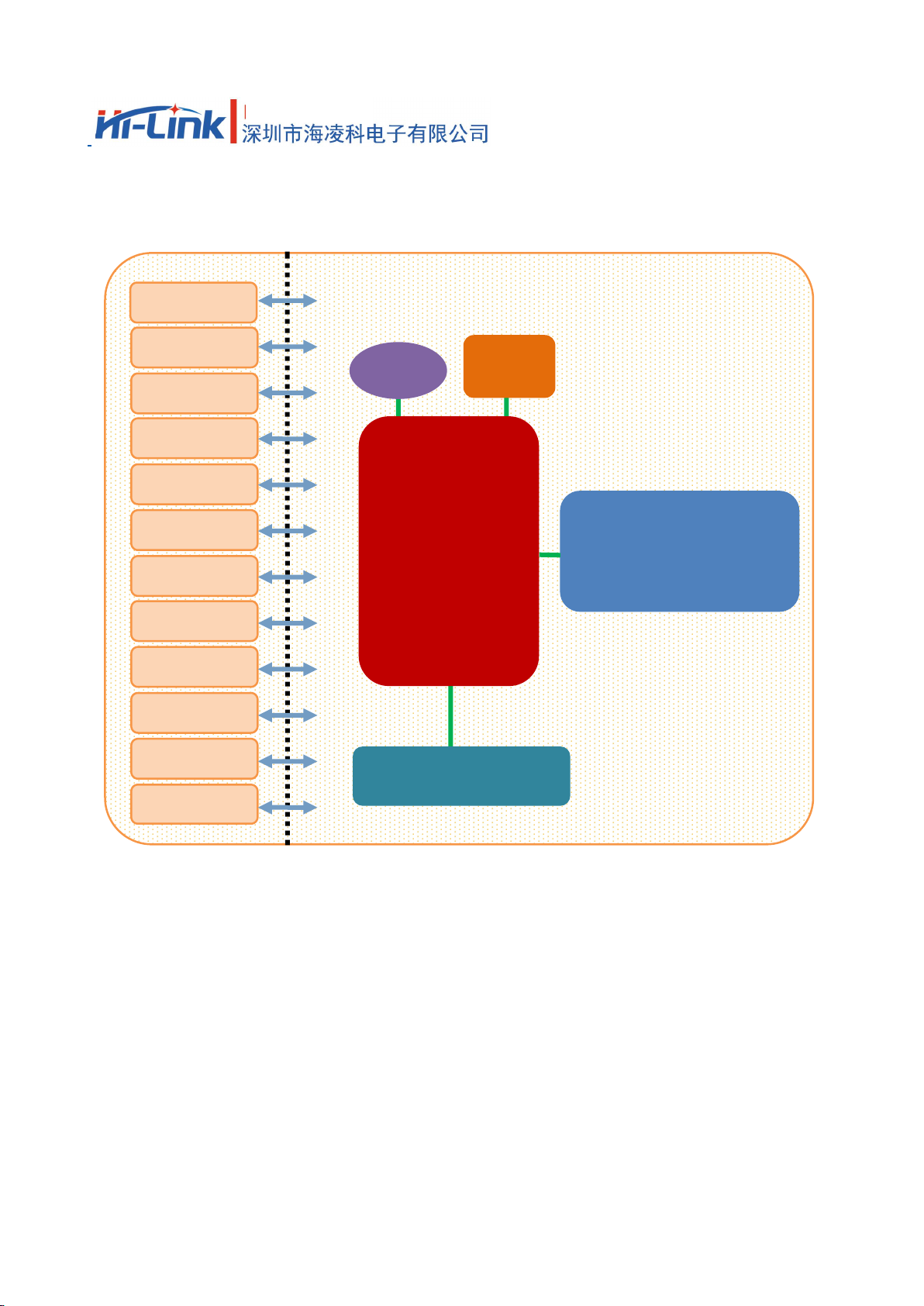
2. Block diagram
EINT
Ethernet
UART
GPIO
PWM
USB_HOST
SPI
SPIS
I2C
I2S
JTAG
SDXC
MT7688KN
3.3V
40MHz
SPI Flash(32MB)
IPEX Connector
HLK-RM08S Block Diagram
Page 5
3
HLK-RM08S
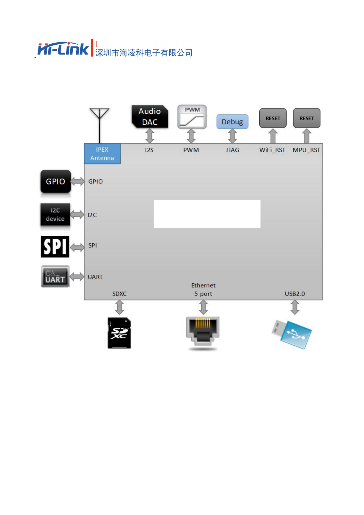
2.1. Typical application
HLK-RM08S
HLK-RM08S typical peripheral interfaces diagram
Page 6
4
HLK-RM08S
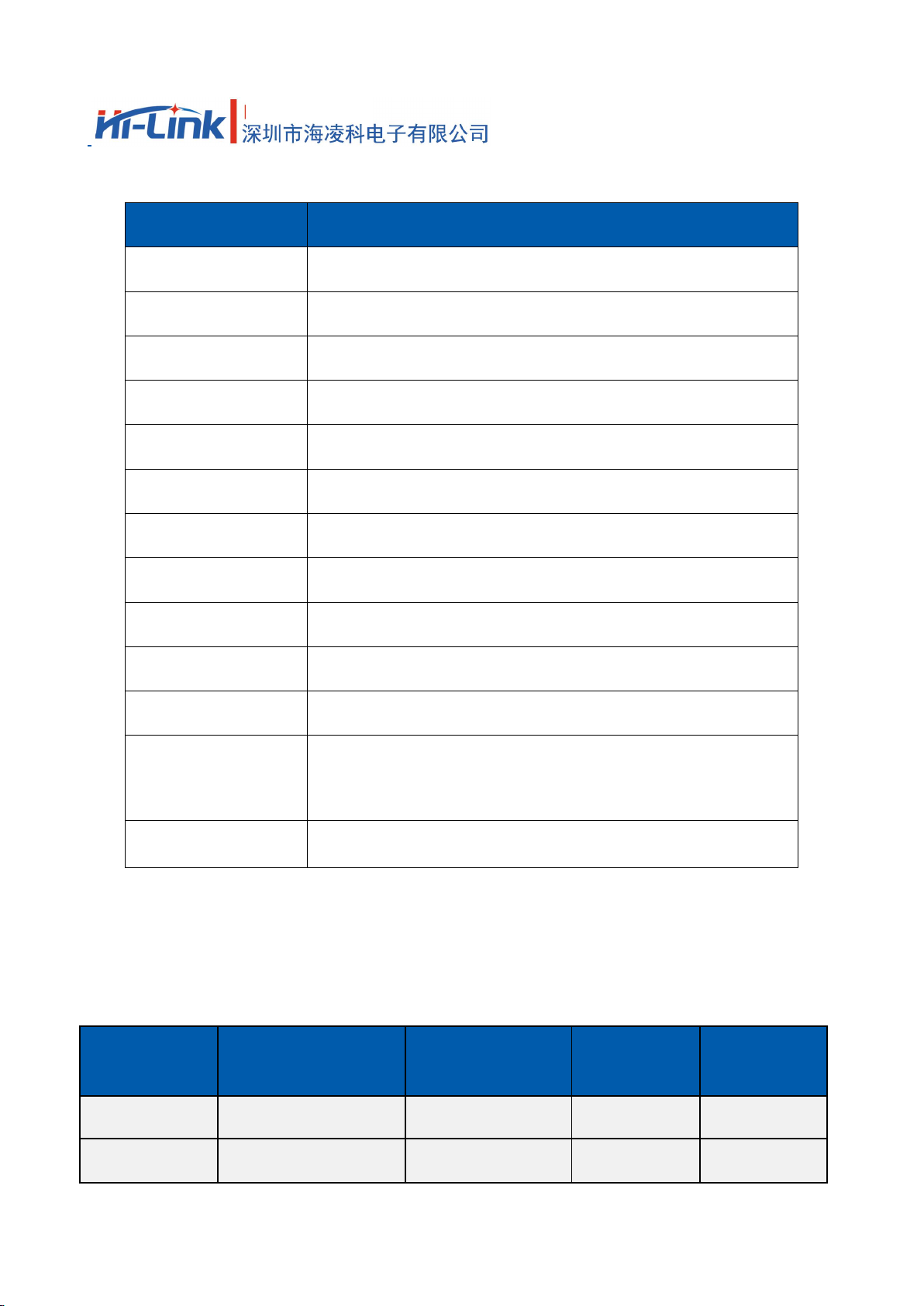
2.2. Specification
Item
Parameter
Model
HLK-RM08S
Main Chip
MT7688KN
I-Cache,D-Cache
64KB,32KB
Kernel
MIPS24KEc
Main frequency
580MHz
RAM
64Mb
Flash
32Mb
RF
1T1R 802.11n 2.4GHz
USB2.0
1
UART
2
Temperature
Environmental temperature:-40℃~85℃
Humidity
working:10~95%(noncondensing)
Storage:5~95%(noncondensing)
Size
17.4mm×25.8mm×2.8mm
3. Electrical characteristics
3.1. Input voltage
Name
Function
Min voltage(V)
Typical
voltage(V)
Max Voltage
(V)
VBAT
Supply voltage
3.2
3.3
3.4
I/O
I/O Voltage
3.2
3.3
3.4
Page 7
5
HLK-RM08S
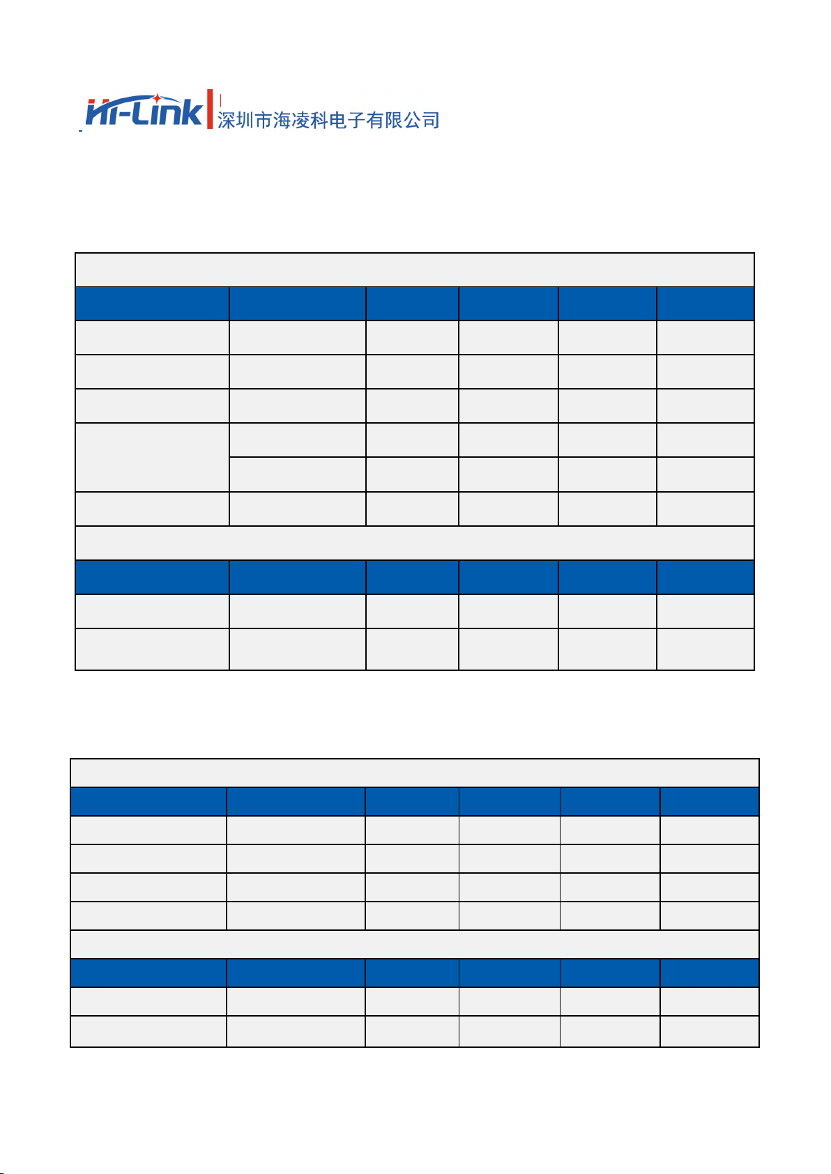
3.2. RF Characteristics
3.2.1. 802.11b 11M
802.11b Transmit (Conductive)
Item
Condition
Min.
Typ.
Max.
Unit
Frequency Range
Channel 1
Channel 13
Tx Power Level
DQPSK
182022
dBm
Frequency Tolerance
-15015
ppm
Spectral Mask
11MHz→22MHz
40
dBr
>22MHz
53
dBr
Modulation Accuracy
All Data Rate
15
%
802.11b Receiver (Conductive)
Item
Condition
Min.
Typ.
Max.
Unit
Frequency Range
Channel 1
Channel 13
Min. Input
11Mbps PER<8%
-91.5
-89.5
-87.5
dBm
3.2.2. 802.11g 54M
802.11g Transmit (Conductive)
Item
Condition
Min.
Typ.
Max.
Unit
Frequency Range
Channel 1
Channel 13
Tx Power Level
OFDM
151719
dBm
Frequency Tolerance
-15015
ppm
Modulation Accuracy
All Data Rate
-31
-28
%
802.11g Receiver (Conductive)
Item
Condition
Min.
Typ.
Max.
Unit
Frequency Range
Channel 1
Channel 13
Min. Input
54Mbps PER<10%
-78.0
-76.0
-74.0
dBm
Page 8

6
HLK-RM08S
3.2.3. 802.11n MCS7(HT20)
802.11n_HT20 Transmit (Conductive)
Item
Condition
Min.
Typ.
Max.
Unit
Frequency Range
Channel 1
Channel 13
Tx Power Level
OFDM
151719
dBm
Frequency Tolerance
-15015
ppm
Modulation Accuracy
All Data Rate
-31
-28
dB
802.11n_HT20 Receiver (Conductive)
Item
Condition
Min.
Typ.
Max.
Unit
Frequency Range
Channel 1
Channel 13
Min. Input
MCS7 PER<10%
-76.5
-74.5
-72.5
dBm
3.2.4. 802.11n_MCS7(HT40)
802.11n_HT40 Transmit (Conductive)
Item
Condition
Min.
Typ.
Max.
Unit
Frequency Range
Channel 1
Channel 13
Tx Power Level
OFDM
15.0
17.0
19.0
dBm
Frequency Tolerance
-15015
ppm
Modulation Accuracy
All Data Rate
-31
-28
dB
802.11n_HT40 Receiver (Conductive)
Item
Condition
Min.
Typ.
Max.
Unit
Frequency Range
Channel 1
Channel 13
Min. Input
MCS7 PER<10%
-76.5
-74.5
-72.5
DBM
Page 9

7
HLK-RM08S
4. PINS DEFINTION
4.1. Pins definition diagram
HLK-RM08S Default pins definition diagram
Page 10

8
HLK-RM08S
4.2. Default pins definition
Pin
Name
( Function
1)
Function 2
Function 3
Function 4
GPIO
Note
1
I2S_DI
PCMDRX
GPIO0
2
I2S_WS
PCMCLK
GPIO2
3
I2S_DO
PCMDTX
GPIO1
4
I2S_CLK
PCMFS
GPIO3
5
SPI_CS1
REF_CLKO
GPIO6
6
SPI_MOSI
GPIO8
7
SPI_CLK
GPIO7
8
SPI_MISO
GPIO9
9
UART_TXD0
GPIO12
Default is serial port
TR
10
UART_RXD0
GPIO13
Default is serial port
TR
11
GPIO0
REF_CLKO
PERST_N
GPIO11
12
MDI_RP_P0
GPIO24
13
MDI_RN_P0
GPIO23
14
MDI_TP_P0
GPIO22
15
MDI_TN_P0
GPIO21
16
MDI_TP_P1
SPIS_CS
PWM_CH0
GPIO14
17
MDI_TN_P1
SPIS_CLK
PWM_CH1
GPIO15
18
MDI_RP_P1
SPIS_MISO
UART_TXD2
GPIO16
19
MDI_RN_P1
SPI_MOSI
UART_RXD2
GPIO17
20
MDI_RP_P2
eMMC_D7
PWM_CH0
GPIO18
21
MDI_RN_P2
eMMC_D6
PWM_CH1
GPIO19
22
MDI_TP_P2
UART_TXD2
eMMC_D5
PWM_CH2
GPIO20
23
MDI_TN_P2
UART_RXD2
eMMC_D4
PWM_CH3
GPIO21
24
MDI_TP_P3
SD_WP
eMMC_WP
GPIO22
25
MDI_TN_P3
SD_CD
eMMC_CD
GPIO23
26
MDI_RP_P3
SD_D1
eMMC_D1
GPIO24
Page 11

9
HLK-RM08S
27
MDI_RN_P3
SD_D0
eMMC_D0
GPIO25
28
MDI_RP_P4
SD_CLK
eMMC_CLK
GPIO26
29
MDI_RN_P4
SD_CMD
eMMC_CMD
GPIO28
30
MDI_TP_P4
SD_D3
eMMC_D3
GPIO29
31
MDI_TN_P4
SD_D2
eMMC_D2
GPIO27
32
USB_DP
Default not available
33
USB_DM
Default not available
34
EPHY_LED4_N
JTAG_RST_N
GPIO30
Com 4 status led
35
EPHY_LED2
JTAG_TMS
GPIO32
Com 2 status led
36
EPHY_LED0
JTAG_TDO
GPIO34
Com 0 status led
37
GND38GND
39
3.3V
Suggested external
power supply current≥
500mA
40
3.3V
41
WLED_N
GPIO35
WiFi status LED
42
EPHY_LED1
JTAG_TDI
GPIO33
Com 1status LED
43
EPHY_LED3
JTAG_CLK
GPIO31
Com 3status LED
44
PORST_N
WIFI reset
45
WDT_RST_N
GPIO37
Watchdog timeout reset
46
UART_TXD1
PWM_CH0
GPIO45
Default is serial port
TR
47
UART_RXD1
PWM_CH1
GPIO46
Default is serial port
TR
48
REF_CLK0
GPIO38
Reference clock output
49
PERST_N
GPIO36
PCIe device reset
50
I2C_SD
GPIO5
51
I2C_CLK
GPIO4
52
GND
53
ANT
Default not connected
54
GND
Page 12

10
HLK-RM08S
Notes:
1,All pins default 1
2,IO drive current is 4mA
3,All TTL is 3.3V
5. Dimensions
Introductions:
1,The size of the module is length 1mm,width 1mm,space 1.4mm , depth 1.8mm.
2,The thickness of the module is 1.8mm.
3, The noted numbers in the picture is the actual size of module,do recommended pad extension around
1mm, internal heat shrink 0.2mm pad, internal thermal pad grounding once do encapsulation.
Do when the package recommended pad extension around the 1mm, 3 internal heat shrink 0.2mm pad,
internal thermal pad grounding.
HLK-RM08S Drawing
Page 13

FCC Warning
This device complies with Part 15 of the FCC Rules. Operation is subject to the following two conditions:
(1) This device may not cause harmful interference, and (2) this device must accept any interference received,
including interference that may cause undesired operation.
NOTE: Any changes or modifications to this unit not expressly approved by the party responsible for compliance
could void the user's authority to operate the equipment.
FCC Radiation Exposure Statement:
This equipment complies with FCC radiation exposure limits set forth for an uncontrolled environment. End users
must follow the specific operating instructions for satisfying RF exposure compliance.
Note 1: This module certified that complies with RF exposure requirement under mobile or fixed condition, this
module is to be installed only in mobile or fixed applications.
A mobile device is defined as a transmitting device designed to be used in other than fixed locations and to
generally be used in such a way that a separation distance of at least 20 centimeters is normally maintained
between the transmitter's radiating structure(s) and the body of the user or nearby persons. Transmitting devices
designed to be used by consumers or workers that can be easily re-located, such as wireless devices associated
with a personal computer, are considered to be mobile devices if they meet the 20 centimeter separation
requirement.
A fixed device is defined as a device is physically secured at one location and is not able to be easily moved to
another location.
Note 2: Any modifications made to the module will void the Grant of Certificatio n, t his module is limited to OEM
installation only and must not be sold to end-users, end-user has no manual instructions to remove or install the
device, only software or operating procedure shall be placed in the end-user operating manual of final products.
Note 3: Additional testing and certification may be necessary when multiple modules are used.
Note 4: The module may be operated only with the antenna with which it is authorized. Any antenna that is of the
same type and of equal or less directional gain as an antenna that is authorized with the intentional radiator may be
marketed with, and used with, that intentional radiator.
Note 5: To ensure compliance with all non-transmitter functions the host manufacturer is responsible for ensuring
compliance with the module(s) installed and fully operational. For example, if a host was previously authorized as
an unintentional radiator under the Declaration of Conformity procedure without a transmitter certified module
and a module is added, the host manufacturer is responsible for ensuring that the after the module is installed and
operational the host continues to be compliant with the Part 15B unintentional radiator requirements. Since this
may depend on the details of how the module is integrated with the host, ShenZhen HaiLingKe Electronic co., Ltd.
shall provide guidance to the host manufacturer for compliance with the Part 15B requirements.
Page 14

Note 6: FCC ID label on the final system must be labeled with “Contains FCC ID: 2AD56HLK-RM08S” or
“Contains transmitter module FCC ID: 2AD56HLK-RM08S”.
 Loading...