

Page 1
HLK-M50
niki@hlktech.com
Specification
Shenzhen HaiLingKe Electronic co.,Ltd
HLK-M50 SPEC.
.
Version:V1.0 Date changed:2017-12-27 All right reserved@ Shenzhen Hi-Lin Electronic company
Page 2

HLK-M50
niki@hlktech.com
Catalogue
1. PRODUCT INTRODUCTION .............................................................................................................................. 1
1.1.
1.2.
1.3.
2. FUNCTIONAL DIAGRAM ......................................................................................................................................... 3
3.SPECIFICATIONS ........................................................................................................................................................ 3
3.1 SYSTEM MEMORY .................................................................................................................................................. 3
3.2 INTERFACE ............................................................................................................................................................... 4
3.3 INTERFACE EXTENSION APPLICATION EXAMPLE...................................................................................... 5
3.4 POWER ....................................................................................................................................................................... 5
HLK-M50 MODULE TYPE.............................................................................................................................. 1
WLAN FEATURES............................................................................................................................................ 2
MCU FEATURES .............................................................................................................................................. 2
Specification
4. MODULE PIN DEFINITION ..................................................................................................................................... 6
4.1 PIN DIAGRAM DEFINITION ................................................................................................................................. 6
4.2 DEFAULT PIN DEFINITION ................................................................................................................................... 7
4.3 GPIO ALTERNATE FUNCTION AND FUNCTION PIN POSITION ................................................................. 8
5. MODULE SIZE CHART ............................................................................................................................................. 8
6. TYPICAL APPLICATION CIRCUIT ........................................................................................................................ 9
7. RECOMMENDED REFLOW TEMPERATURE ..................................................................................................... 9
FCC W
ARNING
............................................................................................................................................................. 11
Page 3
HLK-M50
niki@hlktech.com
Specification
1. Product introduction
The HLK-M50 WiFi module is a low-power chip that integrates MCU, PMU, clock, and IEEE802.11b / g / n
MAC / PHY / radio.
Module supports 2.4GHz IEEE802.11b / g / n, USB Host and Device 2.0 HS, Micro SD card (SDMMC
interface), UART, I2C, I2S, PMW, SPI and other interfaces, analog keys (GPADC0).
Software using mbedOS5.1 operating system, has two versions : WiFi serial transmission function version
and secondary development.
Second development version provides rich development interface, users can develop their own applications
based on mbedOS through C or C ++. Development kit to provide a large number of guidance documents and test
routines to facilitate rapid development of users.
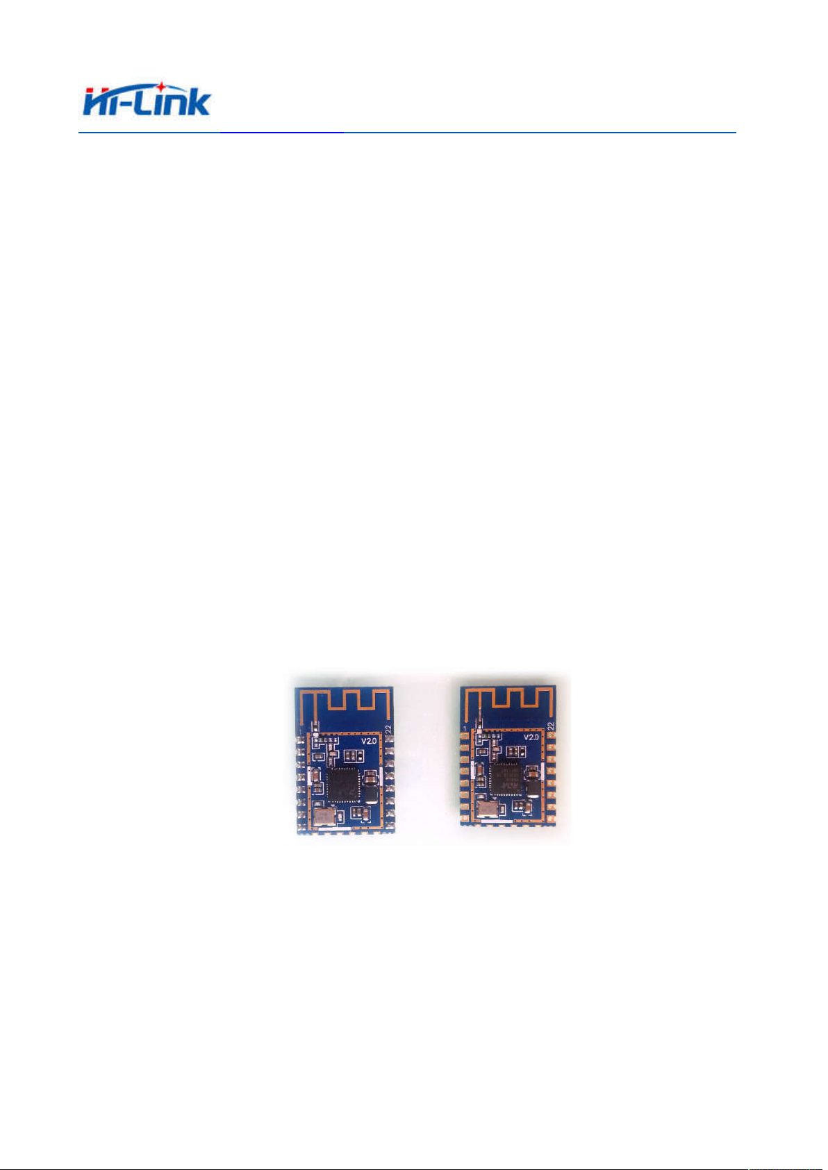
1.1. HLK-M50 Module Type
Pin section and SMD section front
Page 1 of 12
Page 4

HLK-M50
niki@hlktech.com
1.2. WLAN Features
Single-chip integrated MAC/PHY/Radio
Supports 2.4GHz IEEE 802.11b/g/n
Integrated PA, LNA
20/40MHz bandwidth, maximum 150Mbps
Support WPA, WPA2, WEP, TKIP,CCMP
Support STA, softAP, P2P, STA+softAp,STA+P2P
Support A-MPDU, A-MSDU, HT-BA
Lightweight TCP / IP protocol stack
Specification
1.3. MCU Features
Integrated ARM-CM4 MCU, the maximum clock frequency of 160MHz
Integrated MPU and mbed uvisor
Support external psram interface
Built-in 8Mbit SPI flash
Function pin position programmable
Available external rising / falling edge interrupt or wake-up GPIO
Integrated UART×2/I2S×2/I2C×1/PWM×8/SPI×4/SDMMC×1/USB2.0×1
Integrated 2 channel ADC
Integrated watchdog and low-power timer
Operating system using mbedOS5.1
Page 2 of 12
Page 5
HLK-M50
niki@hlktech.com
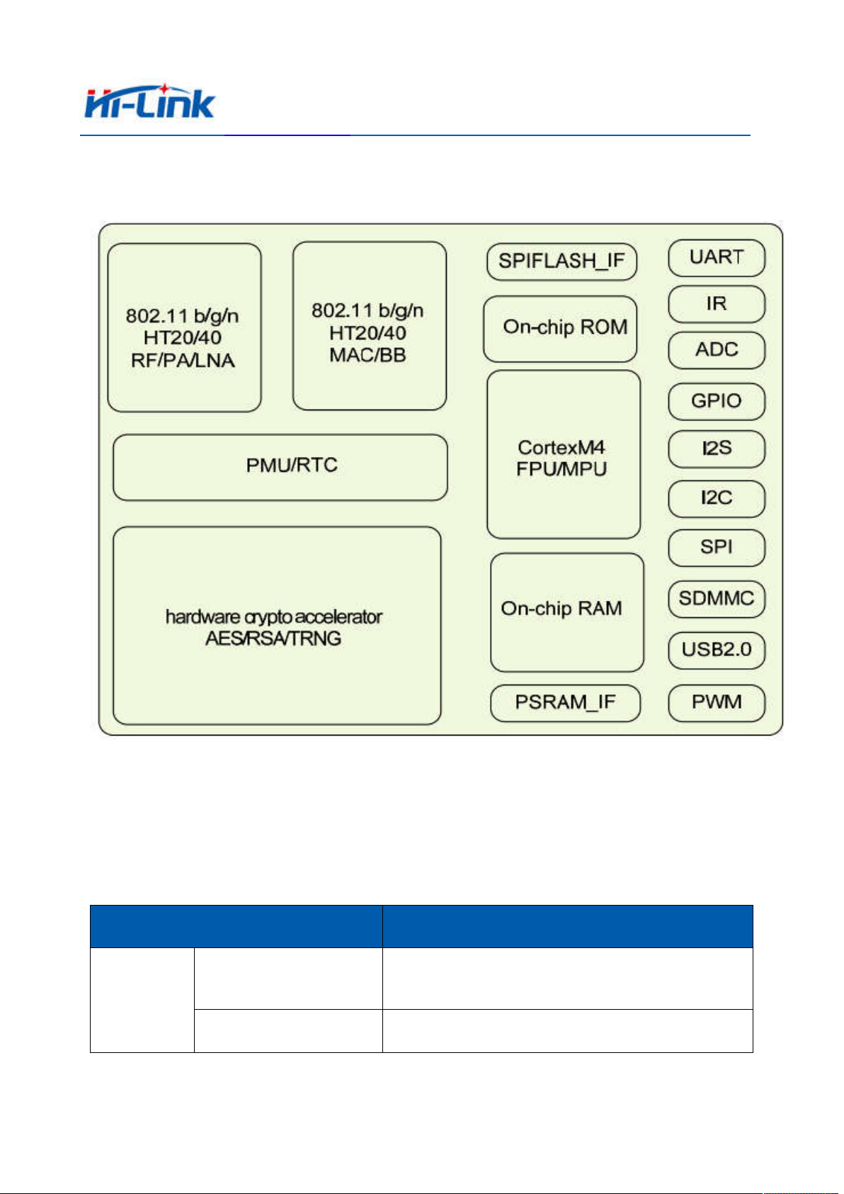
2. Functional diagram
Specification
HLK-M50 Module functional diagram
3.Specifications
3.1 System memory
Project Parameters
96K Bytes User SRAM
32K Bytes icache
Memory
System
Built-in RAM
Built-in Flash Built-in 8Mbit flash
Page 3 of 12
Page 6

HLK-M50
niki@hlktech.com
3.2 Interface
项目 参数
GPIO
Serial performance
I2S Interface Features
I2C Interface
Performance
supports up to 17 GPIO ports, of which 16 can trigger interrupts
supports up to 2 serial ports, baud rate can be configured to 1200bps -
4Mbps
Supports 2 I2S Interfaces; I2S Host BCLK Supports 96/192/384/512 /
44.1 / 88.2KHz; Supports 16/32 bit per channel, Data Format
Configurable as 16/20 / 24bit or Software Configurable Maximum
24bit per channel)
Supports one I2C standard interface. Support master or slave operation.
There are 3 standard speed modes:
1. Standard mode (<100Kb/s)
2. Fast mode (<400Kb/s)
Specification
PWM Interface
Performance
SPI Interface
SDMMC Interface
3. High-speed mode (<3.4Mb/s)
Supports up to eight PWM interfaces; PWM cycle and duty cycle
programmable, duty cycle can be configured between 0-100; cycle
programmable, the software can choose a different clock to produce
longcycles
As the SPI host, up to 4 SPI slave; SPI clock programmable and
maximum 20Mhz; data length can be configured by software, the
maximum 64bit;
Support 1 SDMMC interface
USB Interface
Support 1 USB interface
Page 4 of 12
Page 7

HLK-M50
niki@hlktech.com
3.3 Interface Extension Application Example
Specification
Note:
1,The figure can be extended function, the common firmware do not support some features, please consult
our FAE if you need.
2,The module factory default is USB HOST。
3.4 Power
Typical
Symbol Function Min.Voltage(V)
Voltage(V)
VBAT Supply voltage range
I/O I/O Input Voltage range
3.3 3.3 3.5 ≥500mA
2.7 3.3 3.6 ≤10mA
Symbol Function Min. Voltage (V) Typical Voltage (V) Maximum Voltage (V) Current (mA)
Maximum
Voltage(V)
Current
(mA)
Page 5 of 12
Page 8

HLK-M50
niki@hlktech.com
VBAT supply voltage range 3.3 3.3 3.5 ≥500mA
I / O I / O Input Voltage Range 2.7 3.3 3.6 ≤10mA
4.
Module pin definition
4.1 Pin Diagram Definition
Specification
HLK-RM08S default Pin diagram definition
Note:
1,The figure is the default definition, the multiplexing function is not listed.
2,Please do not arbitrarily pull of each free function pin, so as cause the module does not start properly.
Page 6 of 12
Page 9

HLK-M50
niki@hlktech.com
4.2 Default Pin definition
Number
1
2
3
4
5
6
7
8
9
10
11
Name Type Description
RST
ADC
GPIO1
GPIO2
GPIO3
GPIO13
GPIO12
3.3V
GPIO23
GPIO22
GPIO21
I RESET signal of the chip
I/O General purpose ADC
I/O General purpose input/output
I/O General purpose input/output
I/O General purpose input/output
I/O General purpose input/output
I/O General purpose input/output
PWR I/O power supply
I/O General purpose input/output
I/O General purpose input/output
I/O General purpose input/output(no interrupt)
Specification
12
13
14
15
16
17
18
19
20
21
22
Pin type definition:
I/O → Digital input/output;
I → Digital input
O → Digital output
GPIO0
GPIO4
GPIO5
GND
GPIO8
GPIO7
GPIO9
USB-DN
USB-DP
RX
TX
I/O General purpose input/output
I/O General purpose input/output
I/O General purpose input/output
GND buck ground
I/O General purpose input/output
I/O General purpose input/output
I/O General purpose input/output
I/O USB negative signal
I/O USB positive signal
I/O UART_RX
I/O UART_TX
A,I → Analog input
A,O → Analog output
A,I/O → Analog input/output
PWR → Power
GND → Ground
Page 7 of 12
Page 10

HLK-M50
niki@hlktech.com
4.3 GPIO alternate function and function pin position
Specification
5. Module size chart
Unit:millimetre(mm)
HLK-M50 Dimension
Page 8 of 12
Page 11

HLK-M50
niki@hlktech.com
6. Typical application circuit
Specification
Note:
This is a schematic diagram of the M50 development test suite. Schematic and PCB source files, please ask
sales.
Module over the furnace, please follow this temperature curve in strict implementation. Reflow temperature
deviation is too large will cause damage to the module!
7. Recommended reflow temperature
Module over the furnace, please follow this temperature curve in strict implementation.Reflow temperature
deviation too large will cause damage to the module!
Page 9 of 12
Page 12

HLK-M50
niki@hlktech.com
Temperature setting (centigrade)
Temper.
area
Up 125 135 155 185 195 225 240 230
Down 125 135 155 185 195 225 240 230
Conveyor speed: 70.0 cm/min.
1 2 3 4 5 6 7 8
Specification
Page 10 of 12
Page 13

HLK-M50
niki@hlktech.com
FCC Warning
Specification
This device complies with Part 15 of the FCC Rules. Operation is subject to the following two
conditions:
(1) This device may not cause harmful interference, and (2) this device must
accept any interference received, including interference that may cause undesired
operation.
NOTE 1: This equipment has been tested and found to comply with the limits for a
Class B digital device, pursuant to part 15 of the FCC Rules. These limits are
designed to provide reasonable protection against harmful interference in a
residential installation. This equipment generates, uses and can radiate radio
frequency energy and, if not installed and used in accordance with the instructions,
may cause harmful interference to radio communications. However, there is no
guarantee that interference will not occur in a particular installation. If this
equipment does cause harmful interference to radio or television reception, which
can be determined by turning the equipment off and on, the user is encouraged to try
to correct the interference by one or more of the following measures:
- Reorient or relocate the receiving antenna.
- Increase the separation between the equipment and receiver.
-Connect the equipment into an outlet on a circuit different from that to which the receiver is
connected.
-Consult the dealer or an experienced radio/TV technician for help.
NOTE 2: Any changes or modifications to this unit not expressly approved by the
party responsible for compliance could void the user's authority to operate the
equipment.
Please notice that if the FCC identification number is not visible when the module is
installed inside another device, then the outside of the device into which the module is
installed must also display a label referring to the enclosed module. This exterior label
Page 11 of 12
Page 14

HLK-M50
niki@hlktech.com
Specification
can use wording such as the following: “Contains FCC ID: 2AD56HLK-M50” any
similar wording that expresses the same meaning may be used.
This equipment complies with FCC radiation exposure limits set forth for an
uncontrolled environment. This transmitter must not be co-located or operating
in conjunction with any other antenna or transmitter. The module is limited to
OEM installation ONLY.
The OEM integrator is responsible for ensuring that the end-user has no manual
instruction to remove or install module.
There is requirement that the grantee provide guidance to the host manufacturer
for compliance with Part 15B requirements.
This module certified that complies with RF exposure requirement under mobile or fixed
condition, this module is to be installed only in mobile or fixed applications.
A mobile device is defined as a transmitting device designed to be used in other than fixed
locations and to generally be used in such a way that a separation distance of at least 20 centimeters
is normally maintained between the transmitter's radiating structure(s) and the body of the user or
nearby persons. Transmitting devices designed to be used by consumers or workers that can be easily
re-located, such as wireless devices associated with a personal computer, are considered to be
mobile devices if they meet the 20 centimeter separation requirement.
Page 12 of 12
 Loading...