

Page 1
HLK-M30-DS V1.0 7/30/2014
HLK-M30 Data Sheet
Overview:
HLK-M30 is a new low-cost embedded UART-WIFI module
(serial port -Wireless) developed by Shenzhen HaiLingKe
Electronic co., Ltd.
This product is an embedded module based on the universal
serial interface network standard,built-in TCP / IP protocol stack,
enabling the user serial port,wireless network (wifi) interface
between the onversions.Through the HLK-M30 module, the
traditional serial devices do not need to change any
configuration,userdata can be transmitted through the Internet
network. Provide a quick solution for the user’s serial devices to
transfer data via WIFI
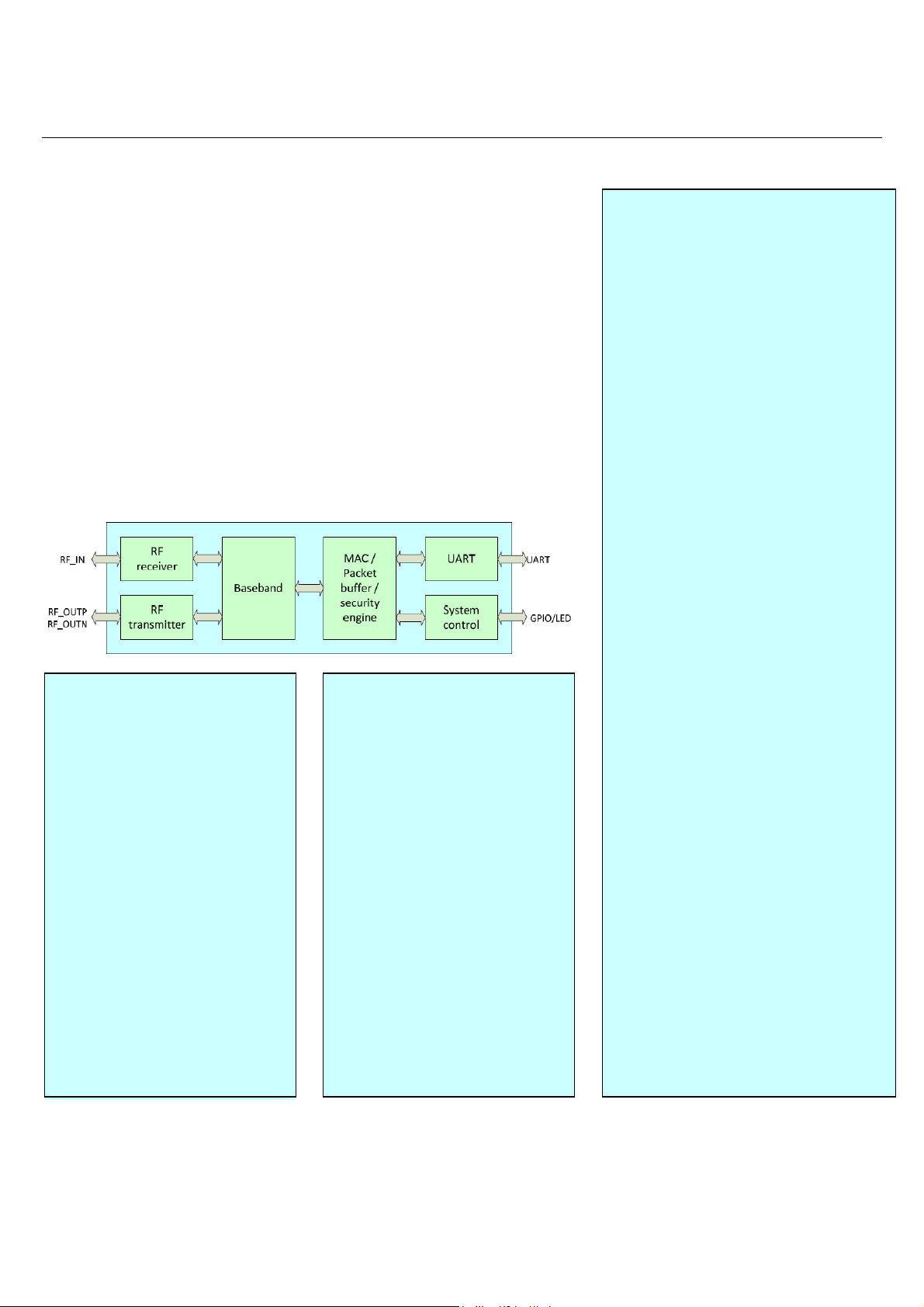
Module Block Diagram
Benefits
Low Power consumption
•
• Ready to use in products
• Minimizes product development
• No RF test required for systems
• Serial to Wifi; Smart;Small;
• Support Smart Connection
• Transparent Transmission
• Serial to Wifi; Smart;Small;
• Compliant with CE and FCC
Applications
• WiFi Led Control
• WiFi Power Switch
• Smart Home;Smart Buliding
• OBDII WiFi Diagnose
• RFID Data Transfer
• Toys and Gaming Peripherals
• Industrial Systems
• Telemetry
• Remote Control
Features:
• 2.4GHz 802.11b/g/n,compatible
• WiFi Sta/Soft AP Mode
• Support Smart Connection
• The range of baudrate: 1200~115200bps
• Support transparent transmission mode
• Support multiple security authenti-cation
mechanisms:
WEP64/WEP128/ TKIP/ AES
WEP/WPA-PSK/WPA2-PSK
• Support wireless roam
•
Support multiple network protocols:
TCP/UDP/ /DHCP/DNS
• Support AT instruction Set
• Device Dimensions 16.3mm*14mm*
2.24mm
Lead-free and RoHS compliant
Page 2
HLK-M30-DS V1.0 7/30/2014
HLK-M30 Data Sheet
1. Introduction
The HLK-M30 module provides designers with a ready made component that provides a fully integrated solution for
applications, using the IEEE802.11 standard in the 2.4-2.5GHz ISM frequency band, including802.11b/g/n, can be quickly
and easily included in product designs. The modules integrate all of the RF components required, removing the need to
perform expensive RF design and test. Products can be designed by simply connecting sensors and switches to the
module IO pins or uart interface. The modules use MTK’s chip Wireless Microcontroller, allowing designers to make use of
the serial interface to connect with their device. Hence, this module allows designers to bring wireless applications to
market in the minimum time with significantly reduced development effort and cost.
The HLK-M30 is an embedded module based on the universal serial interface network standard,built-in T CP / IP
protocol stack, enabling the user serial port, wireless network (wifi) interface between the conversions. Through the
HLK-M30 module, the traditional serial devices do not need to change any configuration; data can b e transmitted through
the Internet network. Provide a quick solution for the user’s serial devices to transfer data via Ethernet Also the HLK-M30
module have FCC modular approvals and is compliant with EU regulations.
2. Specifications
The parameters are defined here.
VDD=3.3V @ +25°C
Typical DC Characteristics Notes
RX Active, HT40, MCS7
TX HT40, MCS7 @15dBm
Typical RF Characteristics Notes
Receive sensitivity -70dBm(802.11n) Use IQview to adjust
Maximum Transmit power 18dBm/15dBm/13.5dBm 802.11b/g/n
RF Port impedance – Ipex onnector 50 ohm 2.4 - 2.5GHz
VSWR (max) 2:1 2.4 - 2.5GHz
Centre frequency accuracy +/-25ppm Additional +/-15ppm allowance
UART 2pins 1200-115200kbps
GPIO 5pins GPIO
VCC 2pins 3.3V+/-10% Two VCC should all connect to power
AN 4pins Analog
GND 23pins GND
Peripherals
150mA
210mA
802.11.n
802.11.n
Notes
Page 3
HLK-M30 Data Sheet
HLK-M30-DS V1.0 7/30/2014
3. Product Development
HaiLingKe supplies all the development tools needed to enable end-product development to occur quickly and efficiently.
These are all available from www.hlktec h.com. A evaluation kits is also available, allowing products to be quickly bread
boarded. Efficient development of software applications is enabled by the provision of a complete, unlimited, software
developer kit.This package provides everything required to develop application code and to trial it with hardware
representative of the final module.
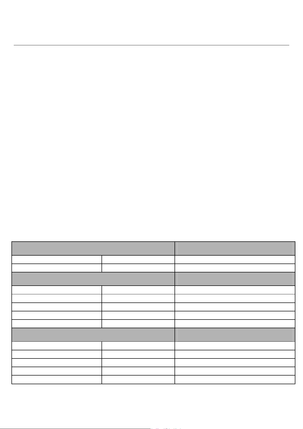
4. Pin Layout
LED
ES/RST
GPIO2
TX
RX
RST
GND
27 28 29 30 31 32 33 34
GND
GPIO1
GPIO0
GND
GND
GND
GND
VDD2
GND
ANT
1
2
3
4
5
6
7
8
9
10 11 12 13 14 15 16 17
GND
GND
Note:VDD1 and VDD2 should all connect to 3.3V. Pin 35/36/37/38 is GND.
35
37
GND
36
38
GND
GND
26
GND
25
GND
24
GND
23
GND
22
GND
21
GND
20
GND
19
VDD1
18
AN4
AN1
AN2
AN3
4.1. Pin Description
Pin No
1
2
Signal Type Description
GPIO1 General GPIO
GPIO0
General GPIO
Page 4

HLK-M30-DS V1.0 7/30/2014
3
GND
Analogue Ground
HLK-M30 Data Sheet
4
5
6
7
8
9
10
11
12
13
14
15
16
17
18
19
GND
GND
GND
VDD2
GND
ANT
GND
GND
GND
GND
GND
AN1
AN2
AN3
AN4
VDD1
Analogue Ground
Analogue Ground
Analogue Ground
Supply Voltage, 3.3V+/-10%
Analogue Ground
Antenna Pin
Analogue Ground
Analogue Ground
Analogue Ground
Analogue Ground
Analogue Ground
Analogue Pin(Reserved)
Analogue Pin(Reserved)
Analogue Pin(Reserved)
Analogue Pin(Reserved)
Supply Voltage, 3.3V+/-10%
20
21
22
23
24
25
26
27
28
29
30
31
32
33
34
35
GND
GND
GND
GND
GND
GND
GND
GND
GND
RST_N
RX
TX
LED
ES/RST
GPIO2
GND
Analogue Ground
Analogue Ground
Analogue Ground
Analogue Ground
Analogue Ground
Analogue Ground
Analogue Ground
Analogue Ground
Analogue Ground
Reset Module
UART RX
UART TX
Staus LED
Exit/Default/Update
General GPIO
Analogue Ground
36
37
38
GND
GND
GND
Analogue Ground
Analogue Ground
Analogue Ground
Page 5

FCC Warning
This device complies with Part 15 of the FCC Rules. Operation is subject to the following two conditions:
(1) this device may not cause harmful interference, and
(2) this device must accept any interference received, including interference that may cause undesired operation.
NOTE: Any changes or modifications to this unit not expressly approved by the party responsible for compliance
could void the user's authority to operate the equipment.
Page 6

FCC Radiation Exposure Statement:
This equipment complies with FCC radiation exposure limits set forth for an uncontrolled environment. End users
must follow the specific operating instructions for satisfying RF exposure compliance.
Note 1: This module certified that complies with RF exposure requirement under portable or mobile or fixed
condition, this module is to be installed only in portable or mobile or fixed appl ications.
A portable device is defined as a transmitting device designed to be used so that the radiating structure(s) of the
device is/are within 20 centimeters of the body of the user
A mobile device is defined as a transmitting device designed to be used in other than fixed locations and to
generally be used in such a way that a separation distance of at least 20 centimeters is normally maintained
between the transmitter's radiating structure(s) and the body of the user or nearby persons. Transmitting devices
designed to be used by consumers or workers that can be easily re-located, such as wireless devices associ ated
with a personal computer, are considered to be mobile devices if they meet the 20 centimeter separation
requirement.
A fixed device is defined as a device is physically secured at one location and is not able to be easily moved to
another location.
Note 2: Any modifications made to the module will void the Grant of Certificatio n, t his module is limited to OEM
installation only and must not be sold to end-users, end-user has no manual instructions to remove or install the
device, only software or operating procedure shall be placed in the end-user operating manual of final products.
Note 3: The device must not transmit simultaneously with any other antenna or transmitter.
Note 4: To ensure compliance with all non-transmitter functions the host manufacturer is responsible for ensuring
compliance with the module(s) installed and fully operational. For example, if a host was previously authorized as
an unintentional radiator under the Declaration of Conformity procedure without a transmitter certified module
and a module is added, the host ma nufacturer is responsible for ensuring that the after the module is installed and
operational the host continues to be comp liant with the Part 15B unintentional radiator requirements. Since this
may depend on the details of how the module is integrated with the host, Shenzhen HaiLingKe Electronic co., Ltd
shall provide guidance to the host manufacturer for compliance with the Part 15B requirements.
Note 5: FCC ID label on the final system must be labeled with “Contains FCC ID: 2AD56HLK-M30” or
“Contains transmitter module FCC ID: 2AD56HLK-M30”.
The transmitter module must be installed and used in strict accordance with the manufacturer's instructions as
described in the user documentation that comes with the host product. Shenzhen HaiLingKe Electronic co., Ltd is
responsible for the compliance of the module in all final hosts.
Page 7

HLK-M30-DS V1.0 7/30/2014
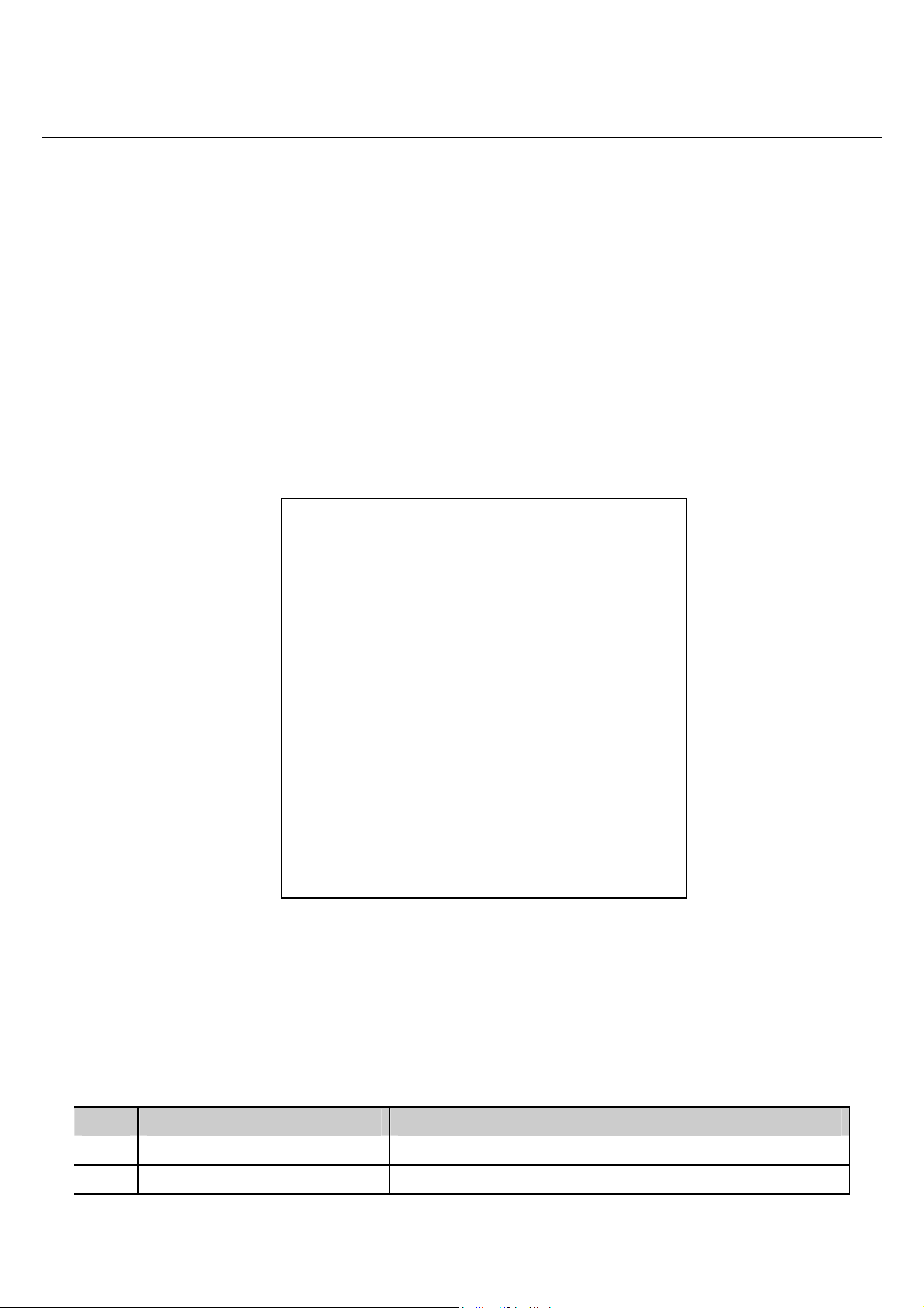
5.Package Information(QFN Packaging)
HLK-M30 Data Sheet
5.1.Ordering Information
Part number Package Operate Temp
HLK-M30 14.1*16.5mm QFN38 -20~70°C
Unit:mm
 Loading...