

Page 1

ShenZhen HaiLingKe Electronic co., Ltd
HLK-7628N User Manual
ETHERNET
WIFI
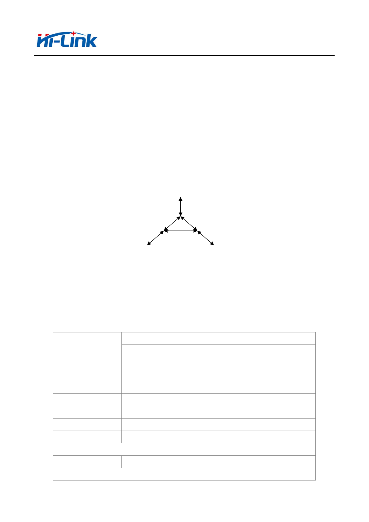
Full function serial network/wifi module
1/49
Page 2

Directory
1 BRIEF INTRODUCTION ............................................................................................................................................ 5
2 SUMMARIZE ................................................................................................................................................................ 5
2.1
TECHNICAL SPECIFICATIONS ..................................................................................................................................... 5
2.2
HARDWARE EXPLANATION ........................................................................................................................................ 6
2.2.1 Mechanical Dimensions ................................................................................................................................... 6
3 QUICK START .............................................................................................................................................................. 7
3.1
FACTORY RESETTING ................................................................................................................................................. 7
3.2
CONFIGURATION NETWORK PARAMETER ................................................................................................................... 7
3.3
CONFIGURATION SERIAL NETWORK PARAMETER ....................................................................................................... 7
4 FUNCTION DESCRIPTION ....................................................................................................................................... 7
4.1
SERIAL TO ETHERNET ............................................................................................................................................... 8
4.2
SERIAL TO WIFI CLIENT ......................................................................................................................................... 8
4.3
SERIAL TO WIFI AP .................................................................................................................................................. 9
4.4
DEFAULT MODE ...................................................................................................................................................... 10
4.5
SERIAL WORK MODE SWITCHING ............................................................................................................................. 10
4.6
SERIAL-NETWORK DATA CONVERSION ..................................................................................................................... 11
4.7
PARAMETER CONFIGURATION DIRECTION ................................................................................................................ 13
5 WEB CONFIGURA TIO N ........................................................................................................................................... 14
5.1
WEB NETWORK CONFIGURATION ........................................................................................................................... 14
5.1.1 Serial to Ethernet- dynamic ip........................................................................................................................ 15
5.1.2 Serial to Ethernet - static ip ........................................................................................................................... 15
5.1.3 Serial to WIFI CLIENT- dynamic ip ............................................................................................................... 15
5.1.4 Serial to WIFI CLIENT- static ip .................................................................................................................... 16
5.1.5 Serial to WIFI AP ........................................................................................................................................... 16
5.2
WEB SERIAL PORT CONFIGURATION ........................................................................................................................ 16
5.3
COMMIT CHANGERS ................................................................................................................................................ 18
6 SERIAL AT COMMAND CONFIGURATION ........................................................................................................ 18
6.1
ENTER AT COMMAND MODE.................................................................................................................................... 18
6.2
AT COMMAND ......................................................................................................................................................... 18
6.2.1 netmode .......................................................................................................................................................... 20
2/49
Page 3

6.2.2 wifi_conf ......................................................................................................................................................... 20
Channel
6.2.3
6.2.4 dhcpc .............................................................................................................................................................. 21
6.2.5 net_ip .............................................................................................................................................................. 22
6.2.6 net_dns ........................................................................................................................................................... 22
6.2.7 dhcpd .............................................................................................................................................................. 22
6.2.8 dhcpd_ip ......................................................................................................................................................... 22
6.2.9 dhcpd_dns ...................................................................................................................................................... 23
6.2.10 dhcpd_time ................................................................................................................................................... 23
6.2.11 net_c ommit ................................................................................................................................................... 23
6.2.12 out_trans ...................................................................................................................................................... 24
6.2.13 remoteip ........................................................................................................................................................ 24
6.2.14 re moteport .................................................................................................................................................... 24
6.2.15 remotepro ..................................................................................................................................................... 24
6.2.16 timeout .......................................................................................................................................................... 25
6.2.17 mode ............................................................................................................................................................. 25
.......................................................................................................................................................... 21
6.2.18 uart ............................................................................................................................................................... 25
6.2.19 uartpacklen ................................................................................................................................................... 26
6.2.20 uartpacktimeout ............................................................................................................................................ 26
6.2.21
escape
.......................................................................................................................................................... 26
6.2.22
tcp_auto
6.2.23 save ............................................................................................................................................................... 27
6.2.24 reconn ........................................................................................................................................................... 27
6.2.25 ver................................................................................................................................................................. 27
6.2.26 Clport ........................................................................................................................................................... 28
6.2.27 RTS
6.2.28 XON_XOFF.................................................................................................................................................. 28
6.2.29 net_wanip ..................................................................................................................................................... 28
6.2.30 tcp_client_check ........................................................................................................................................... 29
6.2.31 S2N_Stat ....................................................................................................................................................... 29
6.2.32 Get_MAC ..................................................................................................................................................... 29
...................................................................................................................................................... 26
(
This function has not been implemented yet) ................................................................................ 28
6.2.33 wifi_ConState ............................................................................................................................................... 29
6.2.34 wifi_Scan ...................................................................................................................................................... 30
6.2.35 suspend ......................................................................................................................................................... 30
6.2.36 C2_remoteip ................................................................................................................................................. 30
6.2.37 C2_re m oteport ............................................................................................................................................. 30
3/49
Page 4

6.2.38 C2_remotepro ............................................................................................................................................... 31
6.2.39 C2_timeout ................................................................................................................................................... 31
6.2.40 C2_mode ...................................................................................................................................................... 31
6.2.41 C2_uart ........................................................................................................................................................ 32
6.2.42 C2_uartpacklen ............................................................................................................................................ 32
6.2.43 C2_uartpacktimeout ..................................................................................................................................... 32
6.2.44 C2_
tcp_auto
............................................................................................................................................... 32
6.2.45 C2_tcp_client_check .................................................................................................................................... 33
6.3
AT COMMAND CONTROL CODE ROUTINE.............................................................................................................................. 33
6.3.1 Configuration information query ................................................................................................................... 33
6.3.2 Serial to Ethernet (dynamic ip addr ess) ......................................................................................................... 34
6.3.3 Serial to Ethernet (static ip address) .............................................................................................................. 35
6.3.4 Serial to wifi client(dynamic ip address) ........................................................................................................ 36
6.3.5 Serial to wifi client(static ip address) ............................................................................................................. 37
6.3.6 Serial to wifi AP ............................................................................................................................................. 38
6.3.7 Factory reset .................................................................................................................................................. 39
7 SERIAL CONFIGURATION TOOL ..................................................................................................................................... 39
7.1
SEARCH MODULE .................................................................................................................................................... 41
7.2
SET PREFERENCES ................................................................................................................................................... 41
7.3
SUBMIT CONFIGURATION ......................................................................................................................................... 42
7.4
USER DATA RETENTION ........................................................................................................................................... 43
INQUIRY CONFIGURATION ........................................................................................................................................ 43
7.5
7.6
ENTER TRANSP ARENT TRANSMISSION ..................................................................................................................... 43
7.7
FACTORY RESET ...................................................................................................................................................... 43
8 SEARCHING DEVICE TOOL .................................................................................................................................. 44
9 FACTORY RESET ...................................................................................................................................................... 45
10 UPGRADE FIRMWARE .......................................................................................................................................... 46
4/49
Page 5
深圳市海凌科电子有限公司 Shenzhen Hi-Link Electronic Co.,Ltd
A
A
Http://www.hlktech.com Tel:0755-36989385 Fax:0755-83575189
1 Brief Introduction
HLK-7628N is a new low-cost embedded UART - ETH - WIFI module developed bu
shenzhen Hi-Link electronic technology co.,ltd.
This product is an embedded module based on the universal serial interface network standard,
built-in TCP/IP protocol stack, enabling the user serial port, Ethernet, wireless network (wifi)
interface between the conversions.
Through the HLK-7628N module, the traditional serial devices do not need to change any
configuration; Data can be transmitted through the internet network. Provide a quick solution for
the user’s serial devices to transfer data via Ethernet.
Serial Com
2 Summarize
2.1 Technical Specifications
Network Standard
Wireless Transmission
Rate
Tracks Number
Frequency range
Emission power
EthernetWIFI(Client/AP)
Picture 1.Function Structure
Table 2-1 Technical Specifications
Wireless:IEEE 802.11n、IEEE 802.11g、IEEE 802.11b
Wired:IEEE 802.3、IEEE 802.3u
11n:Maximum up to 150Mbps
11g:Maximum up to 54Mbps
11b:Maximum uo to 11Mbps
1-14
2.4-2.4835G
12-15DBM
Interface
ntenna
ntenna Type
Functional Parameters
5 Ethernet、2 Serial、1 USB(host/slave)、GPIO
On board antenna /External antenna
5/49
Page 6
深圳市海凌科电子有限公司 Shenzhen Hi-Link Electronic Co.,Ltd
Http://www.hlktech.com Tel:0755-36989385 Fax:0755-83575189
WIFI Work Mode
WDS Function Support WDS wireless bridge connection
Wireless Security
Network Management
Serial to Ethernet
Network Drive/Wireless/Router
Wireless MAC address filtering
Wireless security function switch
64/128/152 bit WEP encryption
WPA - PSK/WPA2 - PSK、WPA/WPA2 security mechanism
Remote Web management
Configuration file import and export
WEB software upgrade
Maximum transmission 500000bps
TCP connection Max connection number>20
UDP connection Max connection number>20
Serial baud rate 1200~500000bps(Support nonstandard bps)
Other parameter
Status indicator light Status indicator
Operating temperature:-20-70℃
Environmental standards
Other performance
Operating humidity:10%-90%RH(non-condensing)
Storage temperature:-40-80℃
Storage humidity:5%-90%RH(non-condensing)
Frequency bandwidth optional:20MHz、40MHz, automatically
2.2 Hardware Explanation
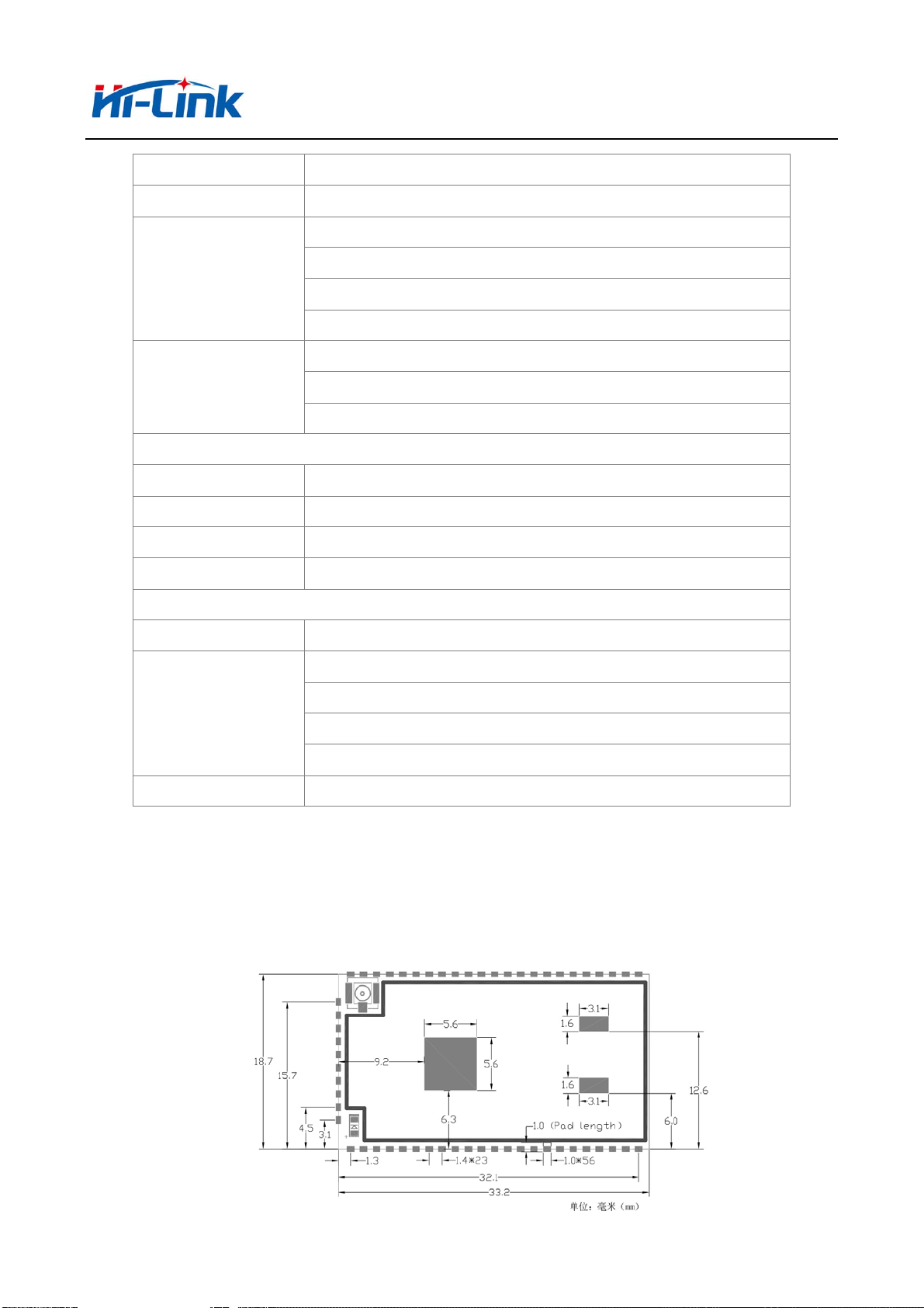
2.2.1 Mechanical Dimensions
HLK-7628N size is shown below:(L*W)=33.2mm*18.7mm*2.2mm
6/49
Page 7

深圳市海凌科电子有限公司 Shenzhen Hi-Link Electronic Co.,Ltd
Http://www.hlktech.com Tel:0755-36989385 Fax:0755-83575189
Note:
1. I/O port electrical level voltage is 3.3V
3 Quick start
3.1 Factory resetting
In order to ensure that all the configuration process correctly, let module restore factory
settings. In factory mode can skip this step. 5V(350mA) to supply power to the module, wait
about 30 seconds after startingthe low WDT/RST pin exceeds Trst, the release of WDT/RST
Pin,the system will automatically restart. The system is already in factory mode.
3.2 Configuration network parameter
Set the PC to static IP mode and then connect it with the module via Ethernet or WIFI. The IP
address is set to 192.168.16.100/255.255.255.0, gateway192.168.16.254.(wifi default and ssid
default password, see this document)open the browser http://192.168.16.254/,enter the web
configuration page,default user name and password is admin/admin. Modity the network
parameter through the web. Now, the module’s IP address is192.168.16.254. Configuration
details can be seen in 5.1.
3.3 Configuration serial network parameter
Open the browser http://192.168.16.254/,enter the serial to network web configuration page.
Configure the serial to network parameter as needed through a wed page. Configuration details can
be seen in 5.2.
4 Function Description
The module can be divided into four modes: default mode, serial to Ethernet, serial to wifi
client, and serial to wifi AP.
7/49
Page 8

深圳市海凌科电子有限公司 Shenzhen Hi-Link Electronic Co.,Ltd
Http://www.hlktech.com Tel:0755-36989385 Fax:0755-83575189
4.1 Serial to Ethernet
HLK-7628NMCU
COM1
DHCP IP
/STATIC IP
ETH1
ETHERNET SERIAL
SWITCH
/ROUTER
Picture 3.Serial to Ethernet model
In this mode,ETH1 enable,WIFI、ETH2 function close. Through the appropriate settings,data
between COM1 and ETH1 network can achieve mutual conversion.
Ethernet can be configured as dynamic IP address(DHCP),can also configured ad static
address(STATIC).
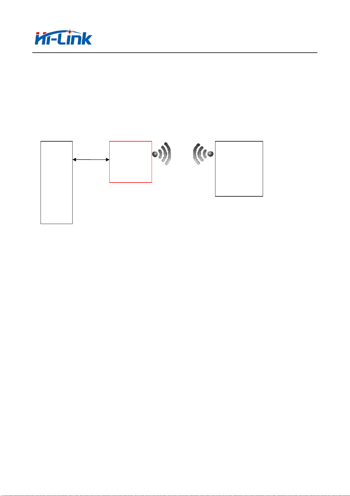
4.2 Serial to WIFI CLIENT
HLK-7628NMCU WIFI AP
COM1
SERIAL
DHCP IP
/STATIC IP
WIFI
Client
Picture 4.Serial to WIFI CLIENT model
In this mode, WIFI enable, module works in the CLIENT mode, ETH1、ETH2function
close.Through the appropriate settings,data between COM1 and ETH1 network can achieve
mutual conversion.
8/49
Page 9
深圳市海凌科电子有限公司 Shenzhen Hi-Link Electronic Co.,Ltd
Http://www.hlktech.com Tel:0755-36989385 Fax:0755-83575189
WIFI CLIENTcan be configured as dynamic IP address(DHCP),can also configured ad static
address(STATIC).
WIFI safety: support all encryption methods at present.
4.3 Serial to WIFI AP
SERIAL
HLK-7628NMCU
COM1
DHCP ENABLE
WIFI
AP
WIFI CLIENT
(PHONE、pad)
Picture 5.Serial to WIFI AP model
In this mode, WIFI enable, module works in the AP mode, ETH1、 ETH2function
close.Through the appropriate settings,data between COM1 and ETH1 network can achieve
mutual conversion.
WIFI safety: support all encryption methods at present.
In this mode, WIFI device can connect with the module and become the device under WIFI
LAN.
9/49
Page 10
深圳市海凌科电子有限公司 Shenzhen Hi-Link Electronic Co.,Ltd
Http://www.hlktech.com Tel:0755-36989385 Fax:0755-83575189
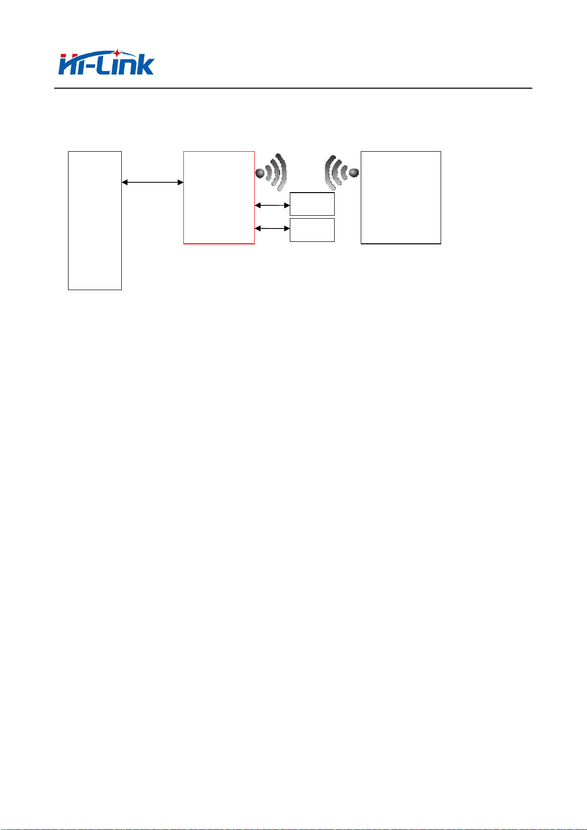
4.4 Default Mode
SERIAL
HLK-7628NMCU
COM1
DHCP ENABLE
WIFI
AP
ETH2
ETH1
LAN
WAN
WIFI CLIENT
(PHONE、pad)
Picture 6.Default mode model
In this mode, WIFI enable, module works in the AP mode, ETH1、ETH2function enable.ETH1
works as WAN,ETH2 works as LAN.Through the appropriate settings,data between COM1
and network can achieve mutual conversion.
WIFI safety: support all encryption methods at present.
In this mode, WIFI device can connect with the module and become the device under WIFI
LAN.
WAN default IP is dynamic IP address.LAN、WIFI for the same local area network, enable by
default DHCP server.
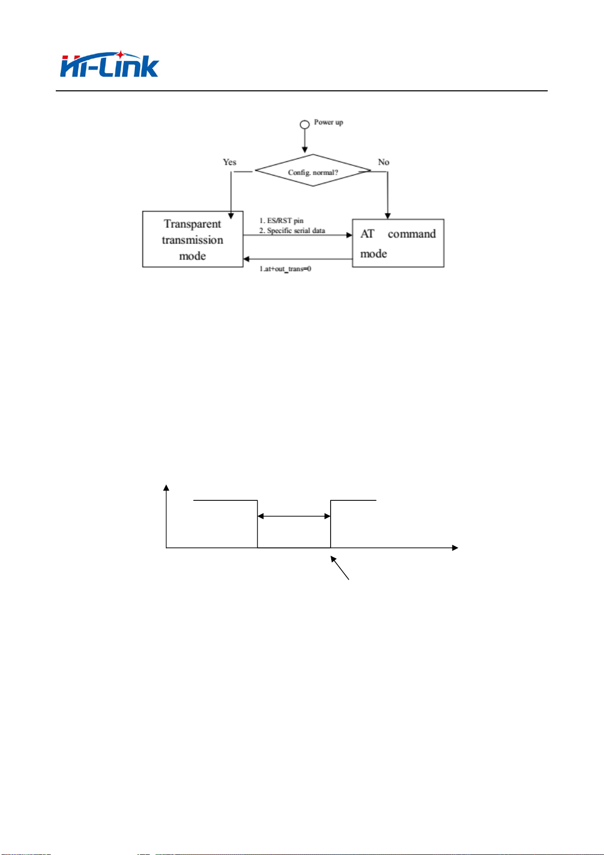
4.5 Serial work mode switching
Module serial work status is defined as two modes: transparent transmission mode, the AT
command mode.
10/49
Page 11
深圳市海凌科电子有限公司 Shenzhen Hi-Link Electronic Co.,Ltd
Http://www.hlktech.com Tel:0755-36989385 Fax:0755-83575189
Picture7.Serial work mode switching
After power on normally, the module will check whether the current network serial port
configuration is normal, if the network connection is normal, the module automatically enters.
There are three kinds of methods for transparent mode entering AT command mode:
1.WDT/RST Pin.
In any state, keep WDT/RST pin low time greater than Tes and less than Trst, the module will
immediately enter the AT command mode.
>Tes
WDT/RST
<Trst
t
AT Command
Picture8. WDT/RST Exit transparent transmission mo
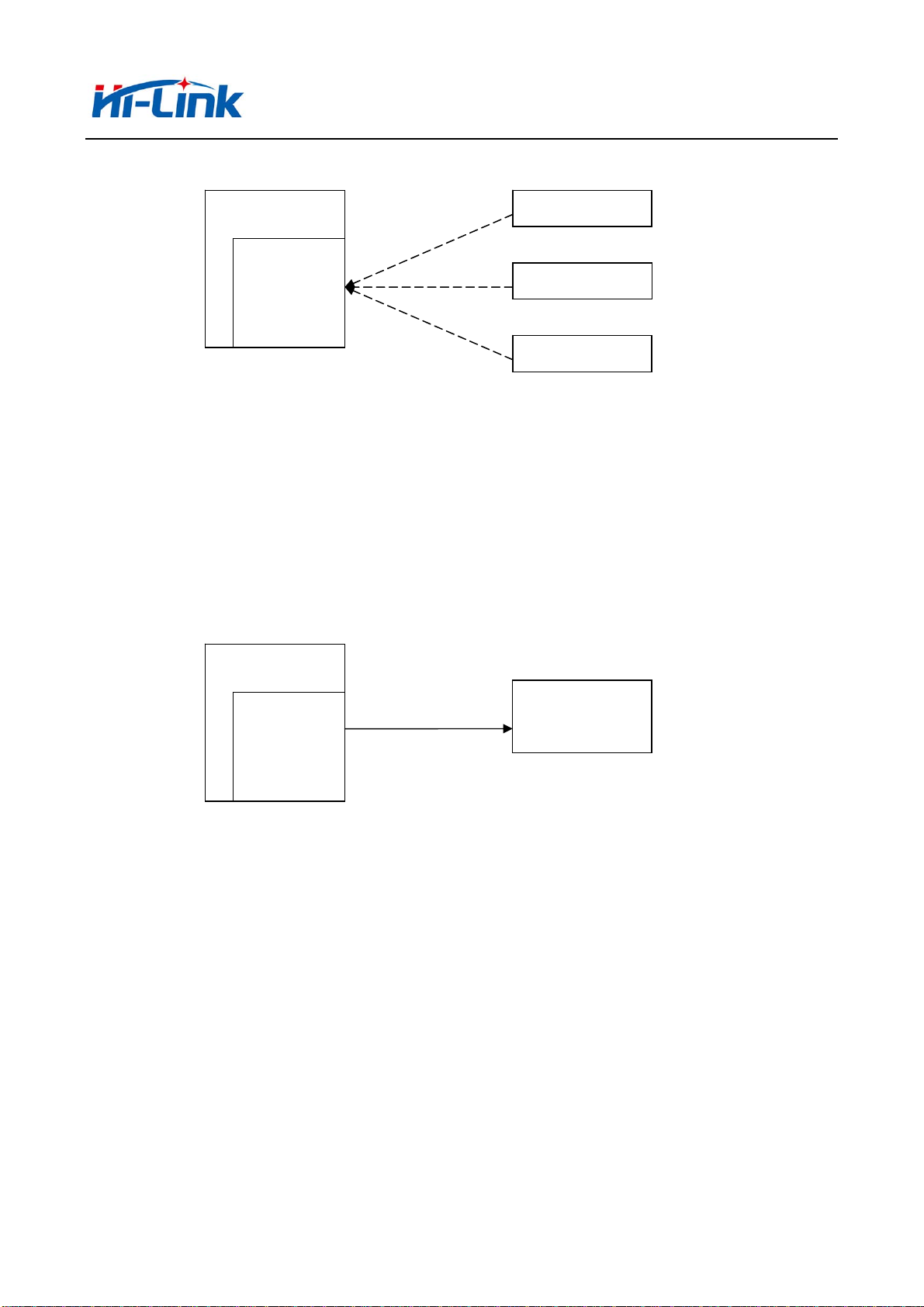
4.6 Serial-network data conversion
Serial data conversion divided into 4 modes:TCP Server、TCP Clinet、UDP Server、UDP
Client。
TCP Server
11/49
Page 12
深圳市海凌科电子有限公司 Shenzhen Hi-Link Electronic Co.,Ltd
Http://www.hlktech.com Tel:0755-36989385 Fax:0755-83575189
HLK-7628N
TCP Client
TCP Server
TCP Client
TCP Client
Picture 10.TCP Server
In this mode, the module is listening on the specified port, waiting for TCP client connection,
if connected, all TCP data is sent directly to the serial port end, the data of the serial end sent to
TCP client end.
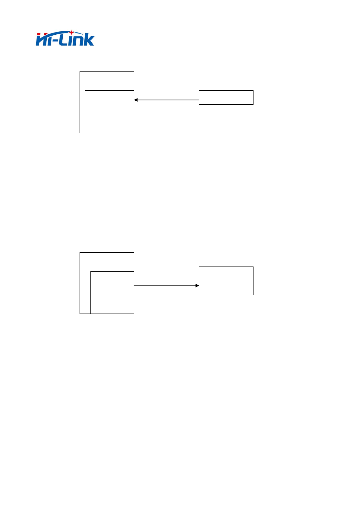
TCP Client
HLK-7628N
TCP Client
TCP Server
图 11.TCP Client
In this mode, the module is connected to the specified domain /IP port. All the data sent from
the TCP server-side end will be sent directly to the serial port, the data from the serial end sent to
the TCP server-side. abnormal network disconnect will cause the module active reconnect. TCP
active reconnect, and otherwise the module will not reconnect.
UDP Server
12/49
Page 13
深圳市海凌科电子有限公司 Shenzhen Hi-Link Electronic Co.,Ltd
Http://www.hlktech.com Tel:0755-36989385 Fax:0755-83575189
HLK-7628N
UDP Server
UDP Client
图 12.UDP Server
In this mode, module open the specified local port, once received is sent to the data port, and
record the last connection on remote information. Serial port to receive data will be sent directly
to the remote IP,recorded port.
UDP Client
HLK-7628N
UDP Client
UDP Server
图 13.UDP Client
In this mode, the module directly sends the serial data to the specified ip, port. The serial data
returned from the server will be distributed to serial port.
4.7 Parameter configuration direction
The module provides two ways for the configuration parameter:
1.WEB page;
2.Serial AT command.
Access to WEB configuration page requires the confirmation of the module’s IP address, as
well as the user name and password that authenticated by WEB.
13/49
Page 14
深圳市海凌科电子有限公司 Shenzhen Hi-Link Electronic Co.,Ltd
Http://www.hlktech.com Tel:0755-36989385 Fax:0755-83575189
Configure parameter through the serial port AT command needs to make the module into the
AT command mode first.
Serial configuration HLK-7628N_CONFIG: Configure the module through AT command,
provide a easier and convenient configuration process through the configuration combination of
each parameter.
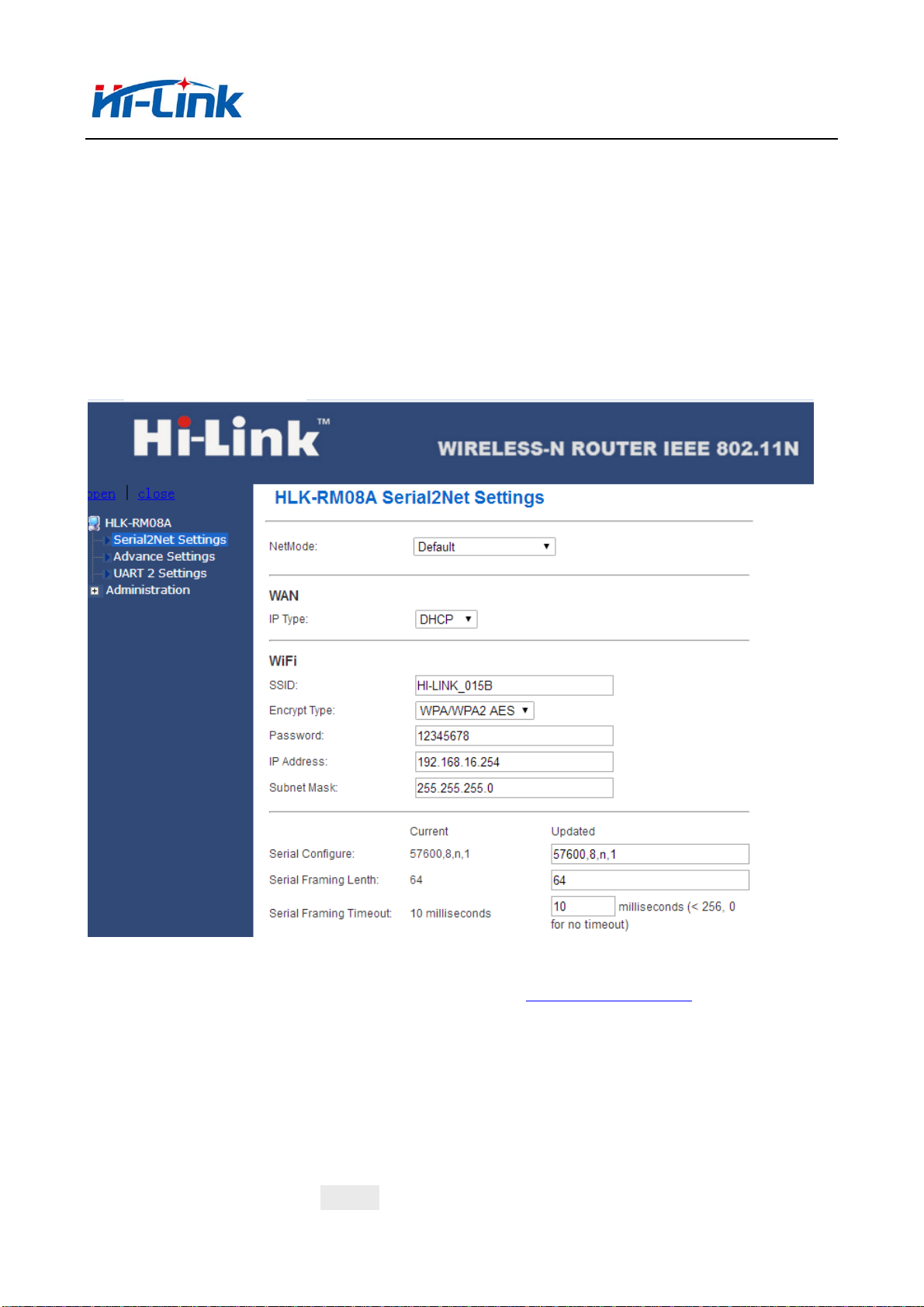
5 WEB configuration
Picture 14.WEB configuration page
Through the correct module address (default addresshttp://192.168.16.254/)you can access to
the web configuration page, the page can be divided onto 3 areas:
1 Network configuration area;
2 Serial function area;
3 Configuration submit area;
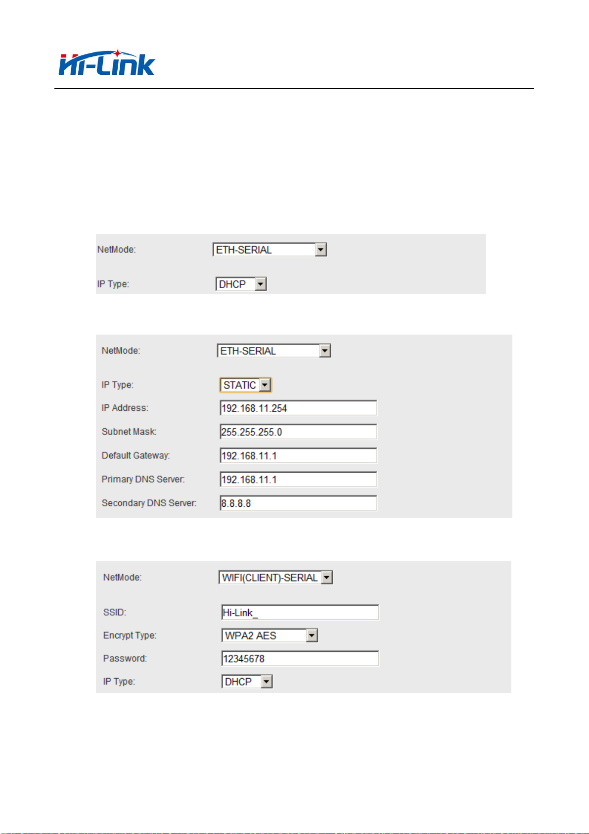
5.1 WEB Network configuration
Net mode selection(NetMode):
14/49
Page 15
深圳市海凌科电子有限公司 Shenzhen Hi-Link Electronic Co.,Ltd
Http://www.hlktech.com Tel:0755-36989385 Fax:0755-83575189
Default – default work mode
ETH -SERIAL – Serial to Ethernet
WIFI(CLIENT)-SERIAL – Serial to WIFI CLIENT
WIFI(AP)-SERIAL) – Serial to WIFI AP
Choose different work mode, the web will show you different page. Mode
configuration page is as follows:
5.1.1 Serial to Ethernet- dynamic ip
Picture 15. Serial to Ethernet- dynamic
5.1.2 Serial to Ethernet - static ip
Picture 16. Serial to Ethernet - static
5.1.3 Serial to WIFI CLIENT- dynamic ip
Picture17. Serial to WIFI CLIENT- dynamic
15/49
Page 16

深圳市海凌科电子有限公司 Shenzhen Hi-Link Electronic Co.,Ltd
Http://www.hlktech.com Tel:0755-36989385 Fax:0755-83575189
5.1.4 Serial to WIFI CLIENT- static ip
Picture18. Serial to WIFI CLIENT- static
5.1.5 Serial to WIFI AP
Picture19. Serial to WIFI AP
5.2 WEB serial port configuration
Serial web configuration is as follows:
16/49
Page 17

深圳市海凌科电子有限公司 Shenzhen Hi-Link Electronic Co.,Ltd
Http://www.hlktech.com Tel:0755-36989385 Fax:0755-83575189
Picture 20. web serial port configuration
Current shows the current configuration,Updated shows the current parameter.
Serial Configure : Serial configuration. The format is as follows:Mbps,data
bits,parity bit and stop bit.
For example:“115200,8,n,1”。
Serial Framing Lenth:The serial frame length
Serial Framing Timeout:The serial frame time
Network Mode:The network mode.Choose Client、Server or none.
Remote Server Domain/IP:The remote server name or IP address.
For example:192.168.11.245 or www.hlktech.com 。
Locale/Remote Port Number:Local or remote port number.Network mode is different
parameters specified remote port number, server is the specified port number.
Network Protocol:The type of network protocol.Used tcp or udp.
Network Timeout:Network timeout. Server network mode, when there is no data
transmission within the timeout period, the connection will be disconnected. 0
specified never disconnected.
17/49
Page 18

深圳市海凌科电子有限公司 Shenzhen Hi-Link Electronic Co.,Ltd
Http://www.hlktech.com Tel:0755-36989385 Fax:0755-83575189
5.3 Commit changers
Click on the Apply configuration of the current page submission. If the network
parameters have been changed, the submission process may require about 25 seconds.
If only modify the serial port function configuration, the submission process will
finished soon.
Click cancel to reload the page, the modified configuration will be lost/
6 Serial AT command configuration
6.1 Enter AT command mode
6.2 AT command
In AT mode, the configuration parameters of the system can be done through the
serial port AT instruction. The command as follows:
at+[command]=[value]\r
According to the different command module will return different value.For
example:”at+remoteip=192.168.11.133\r”Set the ipaddress is 192.168.11.133。
Foe example :”at+remoteip=?\r”check the remote ip address.
Command list is as following:
netmode Network model
wifi_conf WiFi configuration
Channel WiFi channel
dhcpc DHCP Client configuration
net_ip Network IP address
net_dns Network DNS address
dhcpd DHCP server configuration
dhcpd_ip DHCP server IP address
dhcpd_dns DHCP server DNS address
dhcpd_time DHCP server allocates time
net_commit Submit network configuration
out_trans Exit transmission
remoteip Remote server domain name or address
remoteport Local or remote port number
remotepro Network protocol type
18/49
Page 19

深圳市海凌科电子有限公司 Shenzhen Hi-Link Electronic Co.,Ltd
Http://www.hlktech.com Tel:0755-36989385 Fax:0755-83575189
timeout Network timeout
mode Serial network mode
uart Serial configuration
uartpacklen Serial frame length
uartpacktimeout Serial frame time
escape Exit serial transmission
tcp_auto TCP automatic reconnect
save Submit serial port configuration and restart service
reconn Restart service
default Factory reset
reboot Restart module
ver Version
CLport TCP/UDP CLIENT local port
RTS Serial output instructions(485)
XON_XOFF XON/XOFF flow control enable
net_wanip wan ip address
tcp_client_check TCP CLIENT remote state detection
S2N_Stat Serial port function
Get_MAC Get MAC address
wifi_ConState WiFi CLIENT connect status
wifi_Scan WiFi scan
suspend System hang up
C2_uart Serial 2 serial configuration
C2_mode Serial 2 serial network mode
C2_remoteip Serial 2 remote server name or IP address
C2_port Serial 2 local or remote port number
C2_CLport Serial 2 TCP/UDP CLIENT local port
C2_protocol Serial 2 network protocol type
C2_timeout Serial 2 network timeout
C2_uartpacklen Serial 2 serial frame length
C2_uartpacktimeout Serial 2 serial frame time
C2_tcp_auto Serial 2 TCP automatic reconnect
C2_tcp_client_check Serial 2 TCP CLIENT remote state detection
19/49
Page 20

深圳市海凌科电子有限公司 Shenzhen Hi-Link Electronic Co.,Ltd
Http://www.hlktech.com Tel:0755-36989385 Fax:0755-83575189
6.2.1 netmode
Function:
Network mode setting.
Form:
at+netmode=<netmode>\r
Parameter:
Network mode
value Meaning
0 Default mode
1 Ethernet
2 WiFi client
3 WiFi AP
6.2.2 wifi_conf
Function:
Wireless setting.
Form:
at+wifi_conf=<ssid>,<encrypt type>, <password> \r
Parameter:
ssid:Network SSID
encrypt type: Encryption
Encryption
20/49
Page 21

深圳市海凌科电子有限公司 Shenzhen Hi-Link Electronic Co.,Ltd
Http://www.hlktech.com Tel:0755-36989385 Fax:0755-83575189
wpawpa2_tkip wpa/wpa2 tkip
wpawpa2_aes wpa/wpa2 aes
password:password
6.2.3 Channel
value Meaning
none Open network
wep_open Wep encryption, open authentication
wep Wep encryption,keyed authentication
wpa_tkip wpa tkip
wpa_aes wpa aes
wpa2_tkip wpa2 tkip
wpa2_aes wpa2 aes
auto Automatic selection
Function:
WiFi Wireless channel choice.
Form:
at+Channel=<Channel>\r
Parameter:
Channel:0-14.(0-automatic selection)
6.2.4 dhcpc
Function:
Dhcp client enable
Form:
at+dhcpc=<dhcpc>\r
Parameter:
Dhcp client enable
value Meaning
0 Static ip address
1 Dynamic ip address
21/49
Page 22

深圳市海凌科电子有限公司 Shenzhen Hi-Link Electronic Co.,Ltd
Http://www.hlktech.com Tel:0755-36989385 Fax:0755-83575189
6.2.5 net_ip
Function:
The network IP sets. This parameter is invalid when DHCP client is working.
Form:
at+Net_ip=<ip>,<mask>,<gateway>\r
Parameter:
Ip:ip address
Mask:subnet mask
Gateway:gateway
6.2.6 net_dns
Function:
The network DNS sets.his parameter is invalid when DHCP client is working.
Form:
at+Net_dns=<dns1>,<dns2>\r
Parameter:
dns1:Primary DNS address
dns2:Secondary DNS address
6.2.7 dhcpd
Function:
DHCP server enable. 网 This parameter is invalid when the network mode not in AP
mode.
Form:
At+dhcpd=<dhpcd>\r
Parameter:
Dhcp Server enable
value Meaning
0 Close
1 Open
6.2.8 dhcpd_ip
Function:
Dhcp server ip setting.
22/49
Page 23

深圳市海凌科电子有限公司 Shenzhen Hi-Link Electronic Co.,Ltd
Http://www.hlktech.com Tel:0755-36989385 Fax:0755-83575189
Form:
At+Dhcpd_ip=<ip start>,<ip end>,<mask>,<gateway>\r
Parameter:
Ip start:ip start address
Ip end:ip cut-off address
Mask:subnet mask
Gateway:gateway
6.2.9 dhcpd_dns
Function:
Dhcp server dns setting.
Form:
At+Dhcpd_dns=<dns1>,<dns2>\r
Parameter:
dns1:Primary dns address
dns2:secondary dns address
6.2.10 dhcpd_time
Function:
Dhcp server timesetting
Form:
At+Dhcpd_time=<time >\r
Parameter:
time:allocate dhcp valid time to device
6.2.11 net_commit
Function:
Submit network setting.All parameters related to network configuration are
required to be committed after this setting. The command execution time takes about
30s.
Form:
At+ Net_commit=< Net_commit >\r
Parameter:
Submit network settings
value Meaning
23/49
Page 24

深圳市海凌科电子有限公司 Shenzhen Hi-Link Electronic Co.,Ltd
Http://www.hlktech.com Tel:0755-36989385 Fax:0755-83575189
0 Disable
1 Refer
6.2.12 out_trans
Function:
Exit the pass through mode. The function of exiting the pass mode cannot actually
be used on the serial port.
Form:
At+out_trans=<out_trans>\r
Parameter:
Submit network settings
value Meaning
0 Enter transparent transmission
1 Exit transparent transmission
6.2.13 remoteip
Function:
Remote ip or domain name setting.
Form:
At+remoteip=< remoteip >\r
Parameter:
Remote server domain name or ip address.
6.2.14 remoteport
Function:
Remote port setting.
Form:
At+ remoteport=<remoteport>\r
Parameter:
Remoteport:Remote port.
6.2.15 remotepro
Function:
Protocol type setting.
24/49
Page 25

深圳市海凌科电子有限公司 Shenzhen Hi-Link Electronic Co.,Ltd
Http://www.hlktech.com Tel:0755-36989385 Fax:0755-83575189
Form:
At+ remotepro=<remotepro>\r
Parameter:
remotepro setting
value Meaning
None None
Tcp Tcp protocol
Udp Udp protocol
6.2.16 timeout
Function:
Network timeout
Form:
At+timeout=<timeout>\r
Parameter:
Network timeout. Under server network mode,When there is no data transfer in the
timeout period, the connection will be disconnected and the.0 specified never
disconnects.
6.2.17 mode
Function:
Convert mode setting
Form:
At+mode=<mode>\r
Parameter:
Mode setting
value Meaning
None None
Client Client
Server Server
6.2.18 uart
Function:
Serial port configuration setting
Form:
25/49
Page 26

深圳市海凌科电子有限公司 Shenzhen Hi-Link Electronic Co.,Ltd
Http://www.hlktech.com Tel:0755-36989385 Fax:0755-83575189
At+uart=<baud>,<data>,<parity>,<stop>\r
Parameter:
Baud:Bps
Data:data bit
Parity:check bit
Stop:stop bit
6.2.19 uartpacklen
Function:
Frame length of serial port group setting.
Form:
At+uartpacklen =<uartpacklen>\r
Parameter:
uartpacklen:Frame length of serial port group( units:bytes)。
6.2.20 uartpacktimeout
Function:
Group frame time of serial setting
Form:
At+ uartpacktimeout=<uartpacktimeout>\r
Parameter:
uartpacktimeout:Group frame time of serial(Units:ms)。
6.2.21 escape
Function:
Serial port exit transparent transmission enable
Form:
At+ escape=<escape>\r
Parameter:
escape:0 - close,1 - enable
6.2.22 tcp_auto
Function:
TCP automatic reconnection. This function is turned on and the connection will
continue to try to re-establish the connection, regardless of any reason.
26/49
Page 27

深圳市海凌科电子有限公司 Shenzhen Hi-Link Electronic Co.,Ltd
Http://www.hlktech.com Tel:0755-36989385 Fax:0755-83575189
Form:
At+ tcp_auto=<tcp_auto>\r
Parameter:
tcp_auto:0 - Close ,1 - enable
6.2.23 save
Function:
Submit the serial port conversion configuration and restart the service
Form:
At+ save=<save>\r
Parameter:
Submit serial port setting
value Meaning
0 Disable
1 Refer
6.2.24 reconn
Function:
Restart serial conversion service
Form:
At+ reconn =< reconn >\r
Parameter:
Restart serial conversion service
value Meaning
0 Disable
1 Restart serial conversion service
6.2.25 ver
Function:
Firmware version inquiry
Form:
At+ ver =?\r
Parameter:
None.
27/49
Page 28

深圳市海凌科电子有限公司 Shenzhen Hi-Link Electronic Co.,Ltd
Http://www.hlktech.com Tel:0755-36989385 Fax:0755-83575189
6.2.26 Clport
Function:
TCP/UDP CLIENT local port
Form:
At+ CLport=< CLport>\r
Parameter:
Clport:local port number.
6.2.27 RTS (This function has not been implemented yet)
Function:
Serial output indication.In the 485 scenario, a separate pin is usually required
to indicate the reception or transmission status of the 485 transceiver. After this
function is enabled, the GPIO_1 pin indicates the output state of the serial port
as the output pin.
Form:
At+ RTS =< RTS >\r
Parameter:
value Meaning
0 Close
1 Open
6.2.28 XON_XOFF
Function:
XON/XOFF Flow control enable.
Form:
At+ XON_XOFF=< XON_XOFF >\r
Parameter:
RTS
6.2.29 net_wanip
Function:
XON_XOFF
value Meaning
0 Close
1 Open
28/49
Page 29

深圳市海凌科电子有限公司 Shenzhen Hi-Link Electronic Co.,Ltd
Http://www.hlktech.com Tel:0755-36989385 Fax:0755-83575189
wan ip address.
Form:
At+ net_wanip =?\r
Parameter:
无
6.2.30 tcp_client_check
Function:
TCP CLIENT Remote status detection.
Form:
At+ tcp_client_check =< tcp_client_check >\r
Parameter:
tcp_client_check
value Meaning
0 Close
1 Open
6.2.31 S2N_Stat
Function:
Serial function status
Form:
At+ S2N_Stat =?\r
Parameter:
None
6.2.32 Get_MAC
Function:
Get MAC sddress
Form:
At+ Get_MAC =?\r
Parameter:
None
6.2.33 wifi_ConState
Function:
29/49
Page 30

深圳市海凌科电子有限公司 Shenzhen Hi-Link Electronic Co.,Ltd
Http://www.hlktech.com Tel:0755-36989385 Fax:0755-83575189
WiFi CLIENT Connection status
Form
At+ wifi_ConState =?\r
Parameter:
None
6.2.34 wifi_Scan
Function:
WiFi scan
Form:
At+ wifi_Scan =?\r
Parameter:
None
6.2.35 suspend
Function:
System suspension
Form:
At+ suspend =< suspend >\r
Parameter:
suspend
value Meaning
0 Awake
1 Hang up
6.2.36 C2_remoteip
Function:
Serial 2 remote ip or domain setting
Form:
At+ C2_remoteip=< remoteip >\r
Parameter:
Remote server domain name or IP address
6.2.37 C2_remoteport
Function:
Serial 2 remote port setting
Form:
30/49
Page 31

深圳市海凌科电子有限公司 Shenzhen Hi-Link Electronic Co.,Ltd
Http://www.hlktech.com Tel:0755-36989385 Fax:0755-83575189
At+ C2_remoteport=<remoteport>\r
Parameter:
Remoteport:Remote port
6.2.38 C2_remotepro
Function:
Serial port 2 protocol type setting.
Form:
At+ C2_remotepro=<remotepro>\r
Parameter:
Remotepro setting
value Meaning
None None
Tcp Tcp protocol
Udp Udp protocol
6.2.39 C2_timeout
Function:
Serial 2 network timeout
Form:
At+ C2_timeout=<timeout>\r
Parameter:
Network timeout. Under server network mode,When there is no data transfer in the
timeout period, the connection will be disconnected and the.0 specified never
disconnects.
6.2.40 C2_mode
Function:
Serial port 2 conversion mode setting.
Form:
At+ C2_mode=<mode>\r
Parameter:
value Meaning
None None
Mode setting
31/49
Page 32

深圳市海凌科电子有限公司 Shenzhen Hi-Link Electronic Co.,Ltd
Http://www.hlktech.com Tel:0755-36989385 Fax:0755-83575189
Client Client
Server Server
6.2.41 C2_uart
Function:
Serial port 2 serial configuration setting.
Form:
At+ C2_uart=<baud>,<data>,<parity>,<stop>\r
Parameter:
Baud:Bps
Data:data bit
Parity:check bit
Stop:stop bit
6.2.42 C2_uartpacklen
Function:
Serial2 frame length setting
Form:
At+ C2_uartpacklen =<uartpacklen>\r
Parameter:
uartpacklen:Frame length of serial port group(Units:bytes)。
6.2.43 C2_uartpacktimeout
Function:
Serial port 2 serial frame time setting
Form:
At+ C2_uartpacktimeout=<uartpacktimeout>\r
Parameter:
uartpacktimeout:Group frame time of serial(Units:ms)
6.2.44 C2_tcp_auto
Function:
The serial 2TCP auto reconnect. This function is open and any connection is
disconnected for any reason. The module will continue to try to re-establish the
connection
Form:
32/49
Page 33

深圳市海凌科电子有限公司 Shenzhen Hi-Link Electronic Co.,Ltd
Http://www.hlktech.com Tel:0755-36989385 Fax:0755-83575189
At+ C2_tcp_auto=<tcp_auto>\r
Parameter:
tcp_auto:0 - close,1 - enable
6.2.45 C2_tcp_client_check
Function:
Serial 2TCP CLIENT remote status detection.
Form:
At+ C2_tcp_client_check =< tcp_client_check >\r
Parameter:
tcp_client_check
value meaning
0 Close
1 Open
6.3 AT command control code routine
6.3.1 Configuration information query
code:
char *query="\
\
at+netmode=?\r\n\
at+wifi_conf=?\r\n\
at+dhcpd=?\r\n\
at+dhcpd_ip=?\r\n\
at+dhcpd_dns=?\r\n\
at+dhcpd_time=?\r\n\
at+dhcpc=?\r\n\
at+net_ip=?\r\n\
at+net_dns=?\r\n\
at+net_wanip=?\r\n\
\
at+remoteip=?\r\n\
at+remoteport=?\r\n\
at+remotepro=?\r\n\
at+timeout=?\r\n\
at+mode=?\r\n\
at+uart=?\r\n\
33/49
Page 34

深圳市海凌科电子有限公司 Shenzhen Hi-Link Electronic Co.,Ltd
Http://www.hlktech.com Tel:0755-36989385 Fax:0755-83575189
at+uartpacklen=?\r\n\
at+uartpacktimeout=?\r\n\
at+ver=?\r\n\
";
Com_send(query);
Return:
at+netmode=? 0
at+wifi_conf=? Hi-Link,wpa2_aes,12345678
at+dhcpd=? 0
at+dhcpd_ip=? 192.168.14.1,192.168.15.254,255.255.254.0,192.168.15.254
at+dhcpd_dns=? 192.168.15.254,0.0.0.0
at+dhcpd_time=? 86400
at+dhcpc=? 1
at+net_ip=? 192.168.15.254,255.255.254.0,192.168.11.1
at+net_dns=? 192.168.11.1,0. 0.0.0
at+net_wanip=? ,,
at+remoteip=? 192.168.11.245
at+remoteport=? 8080
at+remotepro=? tcp
at+timeout=? 0
at+mode=? server
at+uart=? 115200,8,n,1
at+uartpacklen=? 64
at+uartpacktimeout=? 10
at+ver=? V1.39(Dec 6 2012)
6.3.2 Serial to Ethernet (dynamic ip address)
code:
char *commands_eth="\
\
at+netmode=1\r\n\
at+dhcpc=1\r\n\
\
at+remoteip=192.168.11.245\r\n\
at+remoteport=8080\r\n\
at+remotepro=tcp\r\n\
at+timeout=0\r\n\
at+mode=server\r\n\
at+uart=115200,8,n,1\r\n\
at+uartpacklen=64\r\n\
at+uartpacktimeout=10\r\n\
34/49
Page 35

深圳市海凌科电子有限公司 Shenzhen Hi-Link Electronic Co.,Ltd
Http://www.hlktech.com Tel:0755-36989385 Fax:0755-83575189
at+net_commit=1\r\n\
at+reconn=1\r\n\
";
Com_send(commands_eth);
Reurn:
at+netmode=1 ok
at+dhcpc=1
at+remoteip=192.168.11.245 ok
at+remoteport=8080 ok
at+remotepro=tcp
at+timeout=0 ok
at+mode=server
at+uart=115200,8,n,1 ok
at+uartpacklen=64 ok
at+uartpacktimeout=10 ok
at+net_commit=1
6.3.3 Serial to Ethernet (static ip address)
code:
char *commands_eth_static="\
\
at+netmode=1\r\n\
at+dhcpc=0\r\n\
at+net_ip=192.168.11.254,255.255.255.0,192.168.11.1\r\n\
at+net_dns=192.168.11.1,8.8.8.8\r\n\
\
at+remoteip=192.168.11.245\r\n\
at+remoteport=8080\r\n\
at+remotepro=tcp\r\n\
at+timeout=0\r\n\
at+mode=server\r\n\
at+uart=115200,8,n,1\r\n\
at+uartpacklen=64\r\n\
at+uartpacktimeout=10\r\n\
at+net_commit=1\r\n\
at+reconn=1\r\n\
";
Com_send(commands_eth_static);
Return:
35/49
Page 36

深圳市海凌科电子有限公司 Shenzhen Hi-Link Electronic Co.,Ltd
Http://www.hlktech.com Tel:0755-36989385 Fax:0755-83575189
at+netmode=1 ok
at+dhcpc=0
at+net_ip=192.168.11.254,255.255.255.0,192.168.11.1 ok
at+net_dns=192.168.11.1,8.8.8.8 ok
at+remoteip=192.168.11.245 ok
at+remoteport=8080 ok
at+remotepro=tcp
at+timeout=0 ok
at+mode=server
at+uart=115200,8,n,1 ok
at+uartpacklen=64 ok
at+uartpacktimeout=10 ok
at+net_commit=1
6.3.4 Serial to wifi client(dynamic ip address)
code:
char *commands_wifi_client="\
\
at+netmode=2\r\n\
at+wifi_conf=HI-LINK,wpa2_aes,12345678\r\n\
at+dhcpc=1\r\n\
\
at+remoteip=192.168.11.245\r\n\
at+remoteport=8080\r\n\
at+remotepro=tcp\r\n\
at+timeout=0\r\n\
at+mode=server\r\n\
at+uart=115200,8,n,1\r\n\
at+uartpacklen=64\r\n\
at+uartpacktimeout=10\r\n\
at+net_commit=1\r\n\
at+reconn=1\r\n\
";
Com_send(commands_wifi_client);
Return:
at+netmode=2 ok
at+wifi_conf=HI-LINK,wpa2_aes,12345678 ok
at+dhcpc=1
at+remoteip=192.168.11.245 ok
at+remoteport=8080 ok
at+remotepro=tcp
36/49
Page 37

深圳市海凌科电子有限公司 Shenzhen Hi-Link Electronic Co.,Ltd
Http://www.hlktech.com Tel:0755-36989385 Fax:0755-83575189
at+timeout=0 ok
at+mode=server
at+uart=115200,8,n,1 ok
at+uartpacklen=64 ok
at+uartpacktimeout=10 ok
at+net_commit=1
6.3.5 Serial to wifi client(static ip address)
code:
char *commands_wifi_client_static="\
\
at+netmode=2\r\n\
at+wifi_conf=HI-LINK,wpa2_aes,12345678\r\n\
at+dhcpc=0\r\n\
at+net_ip=192.168.11.254,255.255.255.0,192.168.11.1\r\n\
at+net_dns=192.168.11.1,8.8.8.8\r\n\
\
at+remoteip=192.168.11.245\r\n\
at+remoteport=8080\r\n\
at+remotepro=tcp\r\n\
at+timeout=0\r\n\
at+mode=server\r\n\
at+uart=115200,8,n,1\r\n\
at+uartpacklen=64\r\n\
at+uartpacktimeout=10\r\n\
at+net_commit=1\r\n\
at+reconn=1\r\n\
";
Com_send(commands_wifi_client_static);
return:
at+netmode=2 ok
at+wifi_conf=HI-LINK,wpa2_aes,12345678 ok
at+dhcpc=0
at+net_ip=192.168.11.254,255.255.255.0,192.168.11.1 ok
at+net_dns=192.168.11.1,8.8.8.8 ok
at+remoteip=192.168.11.245 ok
at+remoteport=8080 ok
at+remotepro=tcp
at+timeout=0 ok
at+mode=server
at+uart=115200,8,n,1 ok
37/49
Page 38

深圳市海凌科电子有限公司 Shenzhen Hi-Link Electronic Co.,Ltd
Http://www.hlktech.com Tel:0755-36989385 Fax:0755-83575189
at+uartpacklen=64 ok
at+uartpacktimeout=10 ok
at+net_commit=1
6.3.6 Serial to wifi AP
code:
char *commands_wifi_ap="\
\
at+netmode=3\r\n\
at+wifi_conf=Hi-Link_,wpa2_aes,0000000000\r\n\
at+dhcpd=1\r\n\
at+dhcpd_ip=192.168.16.100,192.168.16.200,255.255.255.0,192.168.16.254\r
\n\
at+dhcpd_dns=192.168.16.254,8.8.8.8\r\n\
at+dhcpd_time=86400\r\n\
at+net_ip=192.168.16.254,255.255.255.0,192.168.16.254\r\n\
at+net_dns=192.168.16.254,8.8.8.8\r\n\
\
at+remoteip=192.168.11.245\r\n\
at+remoteport=8080\r\n\
at+remotepro=tcp\r\n\
at+timeout=0\r\n\
at+mode=server\r\n\
at+uart=115200,8,n,1\r\n\
at+uartpacklen=64\r\n\
at+uartpacktimeout=10\r\n\
at+net_commit=1\r\n\
at+reconn=1\r\n\
";
Com_send(commands_wifi_ap);
return:
at+netmode=3 ok
at+wifi_conf=Hi-Link_,wpa2_aes,0000000000 ok
at+dhcpd=1 ok
at+dhcpd_ip=192.168.16.100,192.168.16.200,255.255.255.0,192.16 8.16.254 ok
at+dhcpd_dns=192.168.16.254,8.8.8.8 ok
at+dhcpd_time=86400 ok
at+net_ip=192.168.16.254,255.255.255.0,1 92.168.16.254 ok
at+net_dns=192.168.16.254,8.8.8.8 ok
at+remoteip=192.168.11.245 ok
at+remoteport=8080 ok
38/49
Page 39

深圳市海凌科电子有限公司 Shenzhen Hi-Link Electronic Co.,Ltd
Http://www.hlktech.com Tel:0755-36989385 Fax:0755-83575189
at+remotepro=tcp
at+timeout=0 ok
at+mode=server
at+uart=115200,8,n,1 ok
at+uartpacklen=64 ok
at+uartpacktimeout=10 ok
at+net_commit=1
6.3.7 Factory reset
code:
char *commands_device_default="\
\
at+default=1\r\n\
at+reboot=1\r\n\
";
Com_send(commands_device_default);
return:
at+default=1
After 30s, the module starts normally and all configuration parameters are factory
configurations,
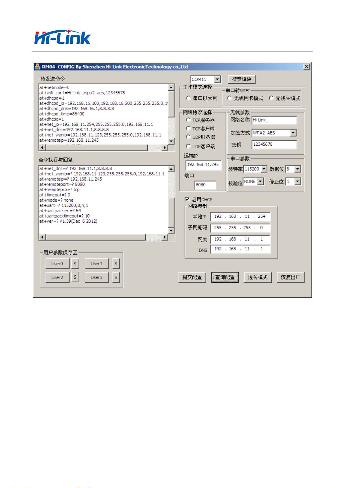
7 Serial configuration tool
HLK-7628N_CONFIG is a tool for configuring modules through serial ports. The tool
interface is as follows:
39/49
Page 40
深圳市海凌科电子有限公司 Shenzhen Hi-Link Electronic Co.,Ltd
Http://www.hlktech.com Tel:0755-36989385 Fax:0755-83575189
1 2
13
3
14
12
5
4
6
7
8
9
10
11
Interface description:
1. Configure serial selection
2. Search module button
3. Work mode select button
4. Wireless configuration parameter
5. Network protocol selection
6. Serial configuration parameter
7. Network IP address configuration
8. Submit configuration button
9. Query configuration button
10. Enter transparent transmission button
Picture15. Serial configuration tool
40/49
Page 41

深圳市海凌科电子有限公司 Shenzhen Hi-Link Electronic Co.,Ltd
Http://www.hlktech.com Tel:0755-36989385 Fax:0755-83575189
11. Restore factory setting button
12. AT command sending
13. AT command information return
7.1 Search module
By configuring the serial port selection, selecting the PC end string slogan,
and clicking the search module button, the tool will search the HLK-7628N module with
the specified serial port, and modules that have been connected and executed in the
AT instruction mode will be searched.The searched module information will be
displayed in the AT instruction execution return information area, as shown below:
Picture16. Serial configuration tool search module
At this point, PC and modules have been able to establish normal AT instruction
communication. All the AT command interaction processes need to be done on the basis
of normal AT instruction communication
7.2 Set preferences
The configuration item 3,4,5,6,7 configures the required function. During
configuration modification, the corresponding AT instruction is generated
immediately after the AT instruction area to be sent. The resulting AT instruction
is not passed to the module immediately. As follows:
41/49
Page 42

深圳市海凌科电子有限公司 Shenzhen Hi-Link Electronic Co.,Ltd
Http://www.hlktech.com Tel:0755-36989385 Fax:0755-83575189
Picture 17. serial configuration tool instructions
7.3 Submit configuration
By clicking the submit configuration button, the tool immediately sends the
instruction of the AT instruction area to be sent to the module. The execution of
the command is displayed in the AT instruction execution return information area.
42/49
Page 43

深圳市海凌科电子有限公司 Shenzhen Hi-Link Electronic Co.,Ltd
Http://www.hlktech.com Tel:0755-36989385 Fax:0755-83575189
Picture 18. Serial configuration tool
7.4 User data retention
The user parameter save area provides the ability to save parameters. By this
function, you can save up to 4 groups of parameters, user0, user1, user2, user3.,
and click the S button next to them, which pops up the confirmation box, as shown
below:
Picture19. Serial configuration tool to save
clicked"yes" button , the instruction of the AT instruction area to be sent will
be saved as the user0 parameter group. After any click on the user0, the user0
parameter group will be called immediately and the AT command area to be sent will
be covered
The saved user parameters are stored as text files in the tools directory. The
filenames are user0, user1, user2, user3.
7.5 Inquiry configuration
Click the query button configuration tool, immediately to send a series of commands
AT configuration module query module current, AT instruction execution results
immediately executed in the AT command returns the information display area, each
configuration item will return along with the corresponding change information.
7.6 Enter transparent transmission
Assuming that the module is already under the AT command, you can enter the
transmission mode immediately by clicking on the transmission mode button。
7.7 Factory reset
click the factory settings button,as shown below:
43/49
Page 44

深圳市海凌科电子有限公司 Shenzhen Hi-Link Electronic Co.,Ltd
Http://www.hlktech.com Tel:0755-36989385 Fax:0755-83575189
Picture 20. erial configuration tool to restore factory settings
Clicked "yes" button , the tool sends the AT command immediately. After about
30s, the module enters the status of the factory settings
8 Searching device tool
HLK-7628N_Discover is a tool for searching HLK-7628N modules on the web side.The
interface is as follows:
Picture 21. Device search tool interface
Click “Discover” button, The tool will immediately search all the HLK-7628N
module in the LAN connected by PC.The search module is displayed immediately in the
message, The information contains ip address 、mac address and version information.
44/49
Page 45

深圳市海凌科电子有限公司 Shenzhen Hi-Link Electronic Co.,Ltd
Http://www.hlktech.com Tel:0755-36989385 Fax:0755-83575189
9 Factory reset
Support the factory setting as following ways.
1.Through the web page.
2.Through the serial AT command.
3.By keeping WDT/RST pin low, the time is greater than Trst.
WDT/RST
>Trst
Reset to Default.
Picture 22. WDT/RST Factory reset
Factory default settings parameter as below:
netmode 0
wifi_conf Hi-Link_,wpa2_aes,12345678
Channel 1
dhcpc 1
net_ip 192.168.11.254,255.255.255.0,192.168.11.1
net_dns 192.168.11.1,8.8.8.8
dhcpd 1
t
dhcpd_ip 192.168.16.100,192.168.16.200,255.255.255.0,192.168.16.1
dhcpd_dns 192.168.16.1,8.8.8.8
dhcpd_time 86400
remoteip 192.168.11.245
remoteport 8080
remotepro tcp
timeout 0
mode server
uart 115200,8,n,1
uartpacklen 64
uartpacktimeout 10
escape 0
45/49
Page 46

深圳市海凌科电子有限公司 Shenzhen Hi-Link Electronic Co.,Ltd
Http://www.hlktech.com Tel:0755-36989385 Fax:0755-83575189
escape2 1
tcp_auto 1
IP address 192.168.16.254
Wifi password 12345678
Web username/password admin/admin
Tes 100ms
Trst 6s
Tescape2 2000ms
C2_uart 57600,8,n,1
C2_mode 0
C2_remoteip 192.168.1.245
C2_port 8081
C2_CLport 0
C2_protocol 1
C2_timeout 0
C2_uartpacklen 64
C2_uartpacktimeout 10
C2_tcp_auto 1
C2_tcp_client_check 1
10 Upgrade firmware
1. Restore factory setting
2. Pc connect module with Ethernet mode, ip:192.168.16.123/255.255.255.0. Browser access
192.168.16.254. User name/password:admin/admin。
3. Open the following page. Select the appropriate firmware, click apply to start the
upgrade.Wait about 1.5 minutes, can not cut off power during the upgrade,
otherwise,module damage may occur.
46/49
Page 47

深圳市海凌科电子有限公司 Shenzhen Hi-Link Electronic Co.,Ltd
Http://www.hlktech.com Tel:0755-36989385 Fax:0755-83575189
Picture 23. upgrade firmware
Attached:Please refer to other technical parameter:HLK-7628N-DATAsheet
FCC Warning
This device complies with Part 15 of the FCC Rules. Operation is subject to the following two
conditions:
(1) This device may not cause harmful interference, and (2) this device must accept any interference
received, including interference that may cause undesired operation.
NOTE 1: Any changes or modifications to this unit not expressly approved by the party responsible
for compliance could void the user's authority to operate the equipment.
47/49
Page 48

深圳市海凌科电子有限公司 Shenzhen Hi-Link Electronic Co.,Ltd
Http://www.hlktech.com Tel:0755-36989385 Fax:0755-83575189
FCC Radiation Exposure Statement:
This equipment complies with FCC radiation exposure limits set forth for an uncontrolled
environment. End users must follow the specific operating instructions for satisfying RF exposure
compliance.
Note 1: This module certified that complies with RF exposure requirement under mobile or fixed condition, this
module is to be installed only in mobile or fixed applications.
A mobile device is defined as a transmitting device designed to be used in other than fixed locations
and to generally be used in such a way that a separation distance of at least 20 centimeters is
normally maintained between the transmitter's radiating structure(s) and the body of the user or
nearby persons. Transmitting devices designed to be used by consumers or workers that can be
easily re-located, such as wireless devices associated with a personal computer, are considered to be
mobile devices if they meet the 20 centimeter separation requirement.
A fixed device is defined as a device is physically secured at one location and is not able to be
easily moved to another location.
Note 2: Any modifications made to the module will void the Grant of Certification, this module is
limited to OEM installation only and must not be sold to end-users, end-user has no manual
instructions to remove or install the device, only software or operating procedure shall be placed in
the end-user operating manual of final products.
Note 3: Additional testing and certification may be necessary when multiple modules are used.
Note 4: The module may be operated only with the antenna with which it is authorized. Any
antenna that is of the same type and of equal or less directional gain as an antenna that is authorized
with the intentional radiator may be marketed with, and used with, that intentional radiator.
Note 5: To ensure compliance with all non-transmitter functions the host manufacturer is
responsible for ensuring compliance with the module(s) installed and fully operational. For example,
if a host was previously authorized as an unintentional radiator under the Declaration of Conformity
procedure without a transmitter certified module and a module is added, the host manufacturer is
48/49
Page 49

深圳市海凌科电子有限公司 Shenzhen Hi-Link Electronic Co.,Ltd
Http://www.hlktech.com Tel:0755-36989385 Fax:0755-83575189
responsible for ensuring that the after the module is installed and operational the host continues to
be compliant with the Part 15B unintentional radiator requirements. Since this may depend on the
details of how the module is integrated with the host, LM Technologies Ltd. shall provide guidance
to the host manufacturer for compliance with the Part 15B requirements.
Note 6: FCC ID label on the final system must be labeled with “Contains FCC ID:
2AD56HLK-7628N” or “Contains transmitter module FCC ID: 2AD56HLK-7628N”.
49/49
 Loading...