

Page 1
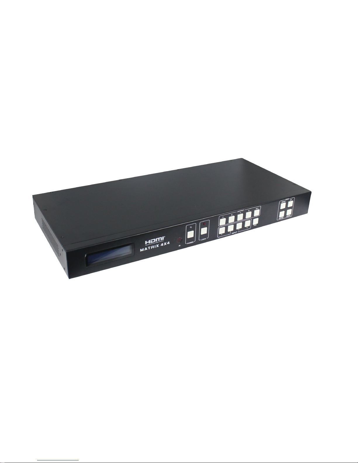
HDBaseT™ 4×4 HDMI Matrix over
CAT5e/6/7
Operation Manual
Ver1.0 Page 1 of 20
Page 2

1.Introduction
The HD BaseT 4x4 HDMI Matrix with simultaneous CAT5e/6/7 and HDMI
outputs connects four HDMI sources to eight displays. This matrix features four
HDMI outputs and each HDMI output is mirrored to provide a CAT-Cable
output which runs simultaneously. It supports the transmission of video
(resolutions up to 1080p Full HD and 4Kx2K@30Hz) and supports high
resolution digital audio formats such as LPCM 7.1CH, Dolby TrueHD, Dolby
Digital Plus and DTS-HD Master Audio.Connect a HD BaseT Receiver to each
of the CAT-Cable outputs to extend the HDMI signal up to 328ft/100m (100m
Version) or 230ft/70m(70m version)for multi-room connectivity. It works with
Blu-Ray players, Set-Top boxes, Home Theater PCs, and game consoles that
connect to an HDMI display. Any source is accessible at all times by any display
by selecting it via the supplied IR Remote Control, RS-232, TCP/IP or by using
the selection buttons on the front panel. This device supports High Definition
Audio, and 3D signal compatibility.
2.Features
• HDMI1.4, HDCP 1.4 and DVI1.0 compliant
• Supports HDMI 3D pass-through
• Supports resolutions from VGA~WUXGA and HD resolutions from
480i~1080p~4Kx2K@30 dependent upon the EDID settings
• Supports transmission distances up to 328ft/100m (100m Version) or
230ft/70m(70m version) through CAT5e/6/7 cable
• Support POE fuction
• Supports simultaneous HDMI and CAT outputs
• Supports wideband IR(30-60Khz) matrix system, IR transport channel can be
forward or backward
• Supports RS-232, remote control, on-panel control and TCP/IP Control
• Supports smart EDID management
Ver1.0 Page 2 of 20
Page 3

• Supports LPCM 7.1CH, Dolby TrueHD, Dolby Digital Plus and DTS-HD
Master Audio transmission
3.Package Contents
HD BaseT 4x4 HDMI Matrix 1pcs
HD BaseT Receiver 4pcs
12V/5A DC power adaptor 2pcs
Operation Manual 1pcs
Wideband IR Tx calbe 4pcs
Wideband IR Rx cable 5pcs
HDMI Matrix IR Remote 1pcs
Mounting ears 2pcs
RS232 cable 1pcs
4.Specifications
Video Bandwidth 297MHz[
10.2Gbps]
Support Video Resolution 480i,576i,480p,576p,720p,1080i,
1080p24/30/50/60.4Kx2K@30;
Input Ports 4×HDMI, 5×IR Receiver, 1×RS-232,
1xRJ-45(Control),4x RS232
Output Ports 4×CAT5e/6/7, 4×IR Blaster, 4×HDMI
HDMI connector Type A 19 pin female
RJ-45 connector WE/SS 8P8C
3.5mm connector (TX and RX) IR Receiver/IR Blaster
ESD Protection Human-body Model:
± 8kV (Air-gap discharge)
± 4kV (Contact discharge)
Power Supply 12 V/5 A DC (US/EU standards,
CE/FCC/UL certified)
Ver1.0 Page 3 of 20
Page 4
Dimensions 440 mm (W)×200 mm (D)×45 mm (H)
Weight 1820 g
Chassis Material Metal
Silkscreen Color Black
Operating Temperature 0 ºC~40 ºC/32 ºF~104 ºF
Storage Temperature −20 ºC~60 ºC/−4 ºF~140 ºF
Relative Humidity 20~90 % RH (non-condensing)
Power Consumption 30 W(max)/0.5w(Standby)
5. PANEL FUNCTIONS
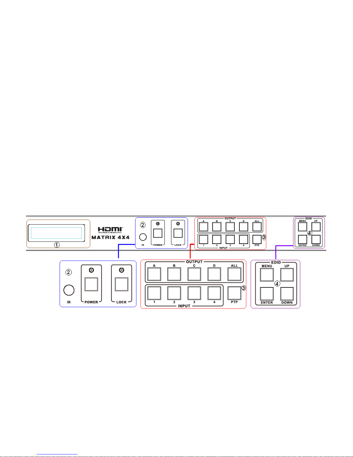
5.1 Front Panel
Part 1. LCM: Displays the information of each input and output setting and
EDID management .
Part 2. IR: IR Receiver window (accepts the remote control signal of this
device only).
POWER: Press this button to power the device on/off. The LED will
illuminate green when the power is on, red when it is in
'Standby' mode.
LOCK: Press this button to lock all the buttons on the panel, press again to
Ver1.0 Page 4 of 20
Page 5

unlock.
Part 3. OUTPUT/INPUT: Press the OUTPUT and INPUT button to select the
output corresponding input.
For example: Press OUPUT ALL>INPUT 1, The OUTPUT A,B,C,D
will be set to INPUT 1.
Press PTP button, The OUTPUT A,B,C,D will corresponding INPUT
1,2,3,4.
Part 4. EDID: Smart EDID management,the LCM will display the EDID
operation.
Press the MENU button will enter the EDID management window, press
UP or DOWN button to select the needed EDID settting, press
ENTER button to select the download input source.it can easy
download any EDID mode to any input source.
Note: The EDID mode table
EDID Mode EDID Description
1 1080i, 2CH AUDIO
2 1080i, DOLBY/DTS 5.1
3 1080i, HD AUDIO
4 1080p, 2CH AUDIO
5 1080p, DOLBY/DTS 5.1
6 1080p, HD AUDIO
7 3D,1080p, 2CH AUDIO
8 3D, 1080p,DOLBY/DTS 5.1
9 3D,1080p, HD AUDIO
10 4k*2k, 2CH AUDIO
11 4k*2k, DOLBY/DTS 5.1
12 4k*2k, HD AUDIO
13 DVI 1024x768
14 DVI 1920X1080
15 DVI 1920X1200
Ver1.0 Page 5 of 20
Page 6

16 Copy from HDMI OUTPUT A
17 Copy from HDMI OUTPUT B
18 Copy from HDMI OUTPUT C
19 Copy from HDMI OUTPUT D
20 Copy from HDBT OUTPUT A
21 Copy from HDBT OUTPUT B
22 Copy from HDBT OUTPUT C
23 Copy from HDBT OUTPUT D
EDID. What is it and what is it used for?
Under normal circumstances, a source device (digital and analog) will require
information about a connected device/display to assess what resolutions and
features are available. The source can then cater its output to send only
resolutions and features that are compatible with the attached device/display.
This information is called EDID (Extended Display Information Data)
and a source device can only accept and read one EDID from a connected
device/display. Likewise, the source an only output one resolution for use by a
connected device/display.
Why is EDID so important with the HDMI Matrix ?
The Matrix is complex piece of technology that replicates and switches between
multiple inputs and outputs. Each connected source device will require one EDID
to read. EDID management is carefully handled by HDMI Matrix to provide a
single EDID for each source to read.
What options do I have to manage the EDID in the HDMI Matrix ?
First, it is important to note that each source device can only output one
video/audio signal type. This includes resolutions and timings. When multiple
devices/displays are used, such as with the HDMI Matrix, it is important to use
devices/displays that have similar or compatible resolutions/features. This will
ensure that the single video/audio signal produced by the source device is
accepted by all of the connected output devices/displays.The user has the option,
Ver1.0 Page 6 of 20
Page 7

through the EDID management window, to choose how the unit will manage the
EDID from multiple HDMI devices/displays. Therefore the user has some
control over the resolutions/features that the source devices will output. The
HDMI Matrix for has a multiple EDID management modes that will control how
the EDID information from multiple devices/displays are combined, ignored, and
routed.
5.2 Rear Panel
Part 1: PC CONTROL
TCP/IP: This port is the link for TCP/IP controls, connect to an active Ethernet
link with an RJ45 terminated cable.
RS232: Connect to a PC or control system with D-Sub 9-pin cable for the
transmission of RS-232 commands.
Part2: IR Channel
IR EXT: if the panel sensor is obstructed or the unit is installed in a closed area
out of infrared line of sight,the IR RX receiver included can be inserted into the
IR EXT port at the rear to extend the IR sensor range and enable local control of
Ver1.0 Page 7 of 20
Page 8

the matrix.
IR IN/OUT: Super IR control system interface. for further details, please refer
to the Super IR system control introduction.
Part3: HDMI INPUT
Connect to the HDMI input source devices such as a DVD player or a Set-top
Box with HDMI cable.
Part4: OUTPUT
The HDMI OUTPUT connect to HDMI equipped TVs or monitors and the
HDBT OUTPUT connect to the HDBT Receiver. The coaxial and analog audio
output connect to the audio amplifier. The TX and RX for RS232 communication
with the HDBT Receiver TX and RX.
Part5: DC and POE POWER INPUT
Plug the 12V/5A DC power supply into the DC12V and 12V/POE port for matrix
power and HDBT Receiver power in.
6. Remote Control
1. Press this button to power on the matrix or set it to
standby mode.
2.Press these button to select output A,B,C,D for
input 1,2,3,4 port.
7. IR Control system(
IR Call-back of
Ver1.0 Page 8 of 20
Page 9

Matrix and Source Devices
)
The matrix is not only a
switcher and extender of
multiple HDMI signals to
multiple HDMI receivers
located remotely, it also passes
IR control signals through the
IR call-back system to the
matrix and HDMI sources for
full, independent control of all
connected inputs from output
locations.
Two-way IR Call-back
Between matrix, Sources and
Displays from Multiple
Locations
A key feature on the matrix is
discrete IR control of the
matrix, sources and displays
from any location – so inputs
at the matrix end can be
controlled at a display location
and displays can be controlled
at the matrix location. This is
accomplished by placing a series of IR Emitters on devices to control and IR
Receivers at all locations you wish to control from to enable the IR signal to
travel both ways via the single Cat5e/6/7 cable.
Ver1.0 Page 9 of 20
Page 10

01. At Matrix end: Insert
the 3.5mm jacks of the IR TX Emitters included with the unit into the IR TX
Emitter ports at the rear of the matrix according to input. The IR signal is added
to the HDMI of the input device so, for example, if the user is watching Blu-ray
on input 1, the IR signal will be directed through the IR TX1 socket to control the
device.
As each IR TX port is allocated to an individual HDMI input port, if the user is
unable to establish IR control of the device, care should be taken to check firstly,
that the IR emitter and HDMI input ports match (Input 1-TX1, Input2-TX2 etc.)
with plugs secured in correct ports, and secondly, that the IR TX emitter sensors
are firmly attached directly to the front of inputs and covering infrared sensor
windows of the source devices.Some later adjustment may be needed to the
location of the sensor to achieve the best performance results - sometimes
moving the sensor to different areas on the source can improve IR performance.
NOTE: Infrared receiving areas of devices can be located by shining a flashlight
onto the front of the device – the sensor should be able to be seen through the
plastic as a small, round object inside.Insert 3.5mm jacks of IR RX receivers into
RX ports, making sure the receivers themselves are placed in clear view to
receive an infrared signal from the remote handset used to control the display
outputs.
02. At display end: Insert the IR RX Receiver jack into the IR RX port of the
display receiver balun, with the receivers themselves placed in clear view on or
near the displays to receive an infrared signal from the remote handset used to
control inputs.Insert the IR TX Emitter jack into the IR TX port of the display
receiver balun, ensuring that the emitter sensor is securely attached to infrared
sensor window of the display.Follow the same connection and positioning for all
baluns/displays connected to the matrix.If all IR TX Emitters and IR RX
Ver1.0 Page 10 of 20
Page 11

Receivers are positioned and connected correctly with sources, displays and
display receivers fully powered and the matrix set to IR call-back enabled and IR
TX Swicth mode activated, two-way IR will now be possible.
Note: Misplaced or poorly secured IR Emitters and Receivers may result in
intermittent IR control signals passed to and from the matrix. Check your
placement and adjust if necessary.
Ver1.0 Page 11 of 20
Page 12

8. HDBT Receiver
Ver1.0 Page 12 of 20
Page 13

1.
RS232 Port: communiate with 4x4 Matrix RS232 port.
2.
IR IN: Connect to the IR Receiver for IR signal reception. Ensure that remote
being used is within the direct line-of-sight of the IR receiver.
3.
IR OUT: Connect the IR Blaster cable included in the package for IR signal
transmission. Pace the IR blaster in direct line-of-sight of the equipment to be
controlled.
4.
HD BaseT IN: Standard HDBaseT signal input port.
5.
DC IN: Plug the 12V DC power supply into the unit.
6.
LINK LED: This red LED illuminate when the Transmitter and Receiver is
connected with CAT5e/6/7 cable.
7.
Data LED: This red LED illuminate when the HD BaseT signal is normal.
8.
HDMI OUT: HDMI Output port.
9.
HDMI OUT LED: This red LED illuminate when the HDMI OUT connect to
the HDTV.
10.
Update: For software update.
9. PC controller user guide
Installation
Matrix controller is a green software. Just copy MatrixController.exe to PC
which is used to control the Matrix by RS232 COM port or TCP/IP to complete
installation.
Preparation
Ver1.0 Page 13 of 20
Page 14

Connect PC and Matrix by RS232 cable (headers of both sides of cable
should be FEMALE) or TCP/IP(local area network)
Power-up Matrix
Double click MatirxController.exe icon to run it
How to control Matrix
“General” page
1. Select RS232 COM or TCP mode
2. Select RS232 COM port
3. Click to connect or disconnect PC and Matrix
4. Select Matrix IP
5. Connet to Matrix IP
6. Search Matrix IP
7. Configure Matrix IP and MAC
Ver1.0 Page 14 of 20
Page 15

8. Click to reset to the factory settings
9. Device information display area
10. Click to refresh device status: include device information displayed in 9 area
and Input/Output Settings on “Matrix” page
11. Click to clear device information
12. Enable or disable Beep
Configure TCP
After action of 7 , edit form will pop-up as below:
1. Select auto or static IP
2. Rewrite the Matrix IP
3. Rewrite the Matrix MAC
“EDID control” page
Ver1.0 Page 15 of 20
Page 16

The controller have 3 methods to set the EDID mode. Manual mode, Copy
mode and open EDID file mode.
1. Select the needed EDID to input port and click set button the EDID will
write to the selected HDMI input ports.
2. Copy the selected HDMI output or HDBT output EDID and click set button
to write to the selected HDMI input ports.
3. Open the user define EDID file and click set button to write to the selected
HDMI input ports.
4. Click the status button to refresh input EDID status.
Ver1.0 Page 16 of 20
Page 17

“Matrix” page
1. LED which display Input number for respective Output
2. Click to select Input port for respective Output port
3. Click to select previous or next Input port for respective Output port
“FW upgrade” page
Ver1.0 Page 17 of 20
Page 18

1. Click to open FW file(file extension is “.fw”)
2. Display the FW file path
3. Displaying the progress of the software upgrade
4. Click to upgrade the Matrix software
5. Display the message of the software upgrade
6. Clear the message of the software upgrade
Ver1.0 Page 18 of 20
Page 19

10. Operate and Connect
1. Connect up to 4 sources such as a Blu-Ray Player, game console, A/V
Receiver, Cable or Satellite Receiver, etc. to the HDMI inputs on the unit. Do
not hotplug! Insert and extract cables carefully with the power switch off.
Connecting and disconnecting while the unit is powered can result in damage
to circuitry.
2. Connect the output HDBT ports and/or HDMI output ports, starting with
output 1, to the HDBT Receiver display receivers (sold separately) (using well
terminated or pre-terminated Cat5e/6/7 cables no longer than 328 ft)
3. If utilizing UTP, connect the output HDMI ports of the HDBT Receiver
display receivers (sold separately) to high-definition displays such as an
HDTV or HD projector that use HDMI inputs. Note that high-speed HDMI
cables are recommended for the distances that are required for each
connection.
Ver1.0 Page 19 of 20
Page 20

4. Plug in IR transmitters to the back of the Matrix Selector Switcher unit (IR
TX), the transmitters are labeled IR TX, place in front of the IR receiver of the
source, ensure that each emitter is placed in front of the IR receiver eye.
Double-sided adhesive tape provided.
5. Plug in IR receivers to the port of the HDBT Receiver display receivers (sold
separately) ,the receivers are labeled IR RX, use provided double-sided
adhesive tape to stick emitters at each display at a desired place that will
receive a remote signal.
6. For power, plug in the source first, followed by the Matrix (power supply
included), followed by the display receivers, followed by each output
connected.
7. Power on each device in the same sequence.
Ver1.0 Page 20 of 20
 Loading...