

Page 1
User Manual
FXS Series Gateway
Shenzhen DBL Co. Ltd.
Http://www.dbltek.com
Support@dbltek.com
sales@
dbltek.com
2010-01-06
Page 2

Contents
1. Product Introduction...................................................4
1.1 General Information....................................................................................................4
1.2 Protocol.........................................................................................................................4
1.3 Hardware Specification..............................................................................................5
1.4 Software Specification................................................................................................5
1.5 List of the Package......................................................................................................5
1.6 Appearance...................................................................................................................6
2. Connection.....................................................................8
2.1. Interface Description:.....................................................................................................8
2.2. Indicator lights explanation:..................................................................................10
2.3. Connection diagram:...............................................................................................11
3. Configuration...............................................................12
3.1. Factory setting parameters: ..................................................................................12
3.2. Log on to the Gateway............................................................................................12
3.2.1. Get IP..................................................................................................................12
3.2.2. Open browser and input IP....................................................................................13
3.3 Gateway Configuration.............................................................................................14
3.3.1. User options.......................................................................................................15
3.3.2. Network Configuration ....................................................................................17
3.3.3. Call Setting........................................................................................................19
3.3.3.1. H.323...........................................................................................................19
3.3.3.1.1 Configuration mode............................................................................21
3.3.3.1.2. Encryption...........................................................................................22
3.3.3.2. H.323 Advanced Setting ...........................................................................22
3.3.3.3. SIP Protocol................................................................................................24
3.3.3.3.1. Configuration Mode...........................................................................26
3.3.3.3.2. SIP Advanced Configuration.............................................................27
3.3.3.3.3. Media Advanced Configuration........................................................28
3.3.3.4. Firewall Traversal......................................................................................29
3.3.3.4.1. H.323 Signaling NAT Traversal.........................................................29
3.3.3.4.2. SIP Signaling NAT Traversal ..............................................................30
3.3.3.4.3. Media NAT Traversal..........................................................................31
3.3.4. Phone Settings...................................................................................................32
3.3.5. Save Changes.....................................................................................................33
3.3.6. Abandon changes ..............................................................................................33
4. Tools...............................................................................34
4.1. Online Upgrade.........................................................................................................34
Page 3

4.2. Change Password......................................................................................................34
4.3. Restore factory settings..........................................................................................34
5. Dialing Rules................................................................35
5.1. Basic rules of grammar...........................................................................................35
5.2. With a limited number of digit dialing rules.......................................................36
6. Understand More........................................................37
6.1. Gateway Initialization.............................................................................................37
6.2. Advanced Configuration..........................................................................................37
6.3. Notes..........................................................................................................................37
Page 4

1. Product Introduction
1.1 General Information
FXS Series Gateway are the performance Gateway, which developed by DBL Co. FXS
Series gateways built-in H.323 and SIP protocols. Highly reliable line detection prevents
the line hanging death in the largest tent. Convenient and practical function of a broken
network escape, when disconnect the network, or VOIP logon fails, FXS to mention the
opportunity to jump directly to the outside PSTN. It can forward outside Caller ID
Number under the SIP protocol, which is an important function of PBX application. Super
Echo Cancellation Algorithm and Balanced Circuit make line echo minimum. Low price,
Stable and performance are pronoun of the FXS Series products,it is the first choice of
PXS Manufacturers, Call Center and System Integrators.
FXS Series mainly include HT_912, HT_922, HT_842R, HT_882.
1.2 Protocol
¾ TCP/IP V4 (IP V6 auto adapt)
¾ ITU-T H.323 V4 Standard
¾ H.2250 V4 Standard
¾ H.245 V7 Standard
¾ H.235 Standard(MD5,HMAC-SHA1)
¾ ITU-T G.711 Alaw/Ulaw, G.729A, G.729AB, and G.723.1 T.38 Voice Codec
¾ RFC1889 Real Time Data Transmission
¾ Proprietary Firewall-Pass-Through Technology
¾ SIP V2.0 Standard
¾ Simple Traversal of UDP over NAT (STUN)
¾ Web-base Management
¾ PPP over Ethernet (PPPOE)
¾ PPP Authentication Protocol (P AP)
¾ Internet Control Message Protocol (ICMP)
¾ TFTP Client
¾ Hyper Text Transfer Protocol (HTTP)
¾ Dynamic Host Configuration Protocol (DHCP)
¾ Domain Name System (DNS)
¾ User account authentication using MD5
¾ Out-band DTMF Relay: RFC 2833 and SIP
Page 5

1.3 Hardware Specification
¾ ARM9E Processor
¾ DSP for voice codec and voice processing
¾ Two 10/100 Base T Ethernet ports with full compliant with IEEE 802.3
¾ LEDS for Ethernet port status
¾ Direct Connect Ethernet
1.4 Software Specification
¾ LINUX OS
¾ Built-in HTTP Web Server
¾ PPPOE Dial-up
¾ NAT Broadband Router Functions
¾ DHCP Client
¾ DHCP Server
¾ Firmware On-line upgrade
¾ PSTN Caller ID transmit
¾ Multiple Language Support
¾ Supported call divert
¾ Supported PSTN auto call out to PSTN
¾ Supported Multi-devices Cooperate Mode(Group Mode)
¾ Supported SMS call out
1.5 List of the Package
a) One Gateway main unit
b) One DC24V/500mA power adaptor
c) One Ethernet cable (2 M)
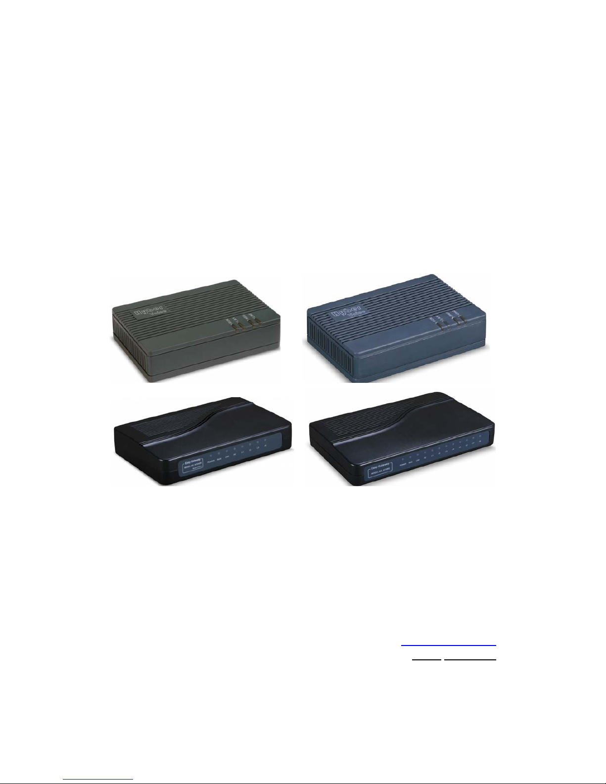
Page 6
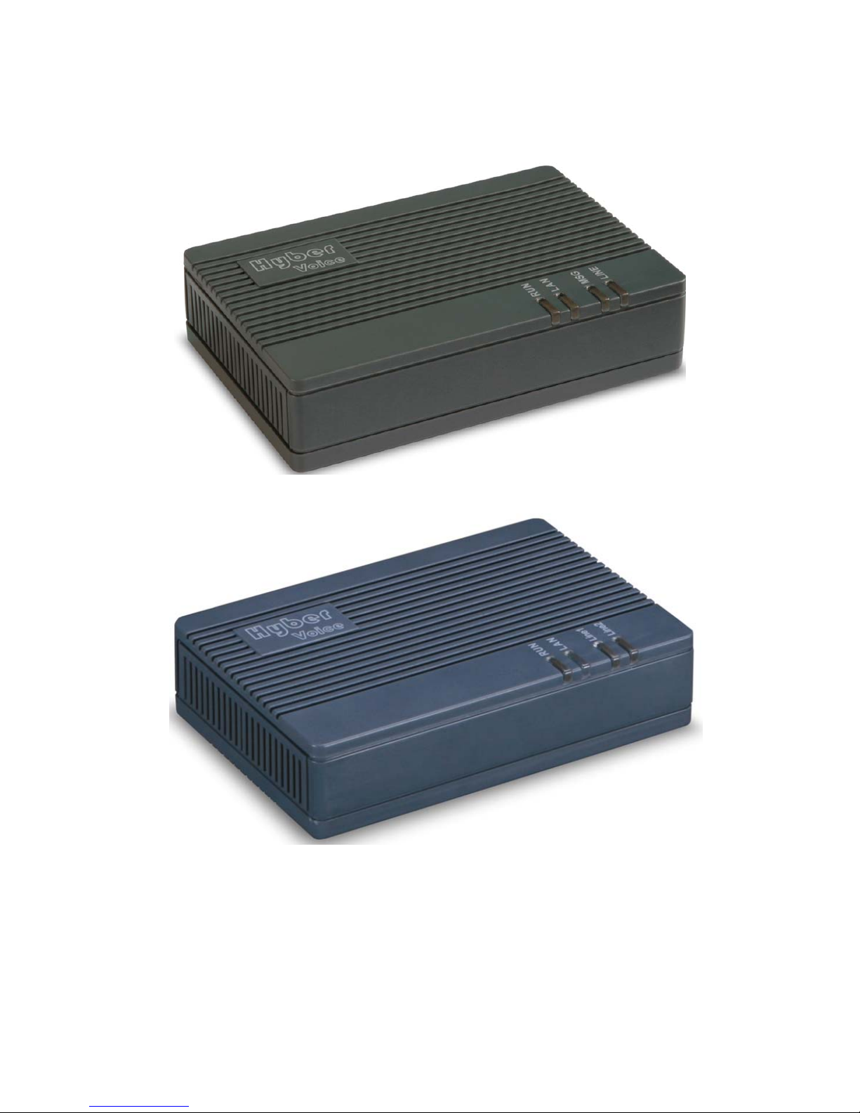
1.6 Appearance
HT_912T
HT_922T
Page 7
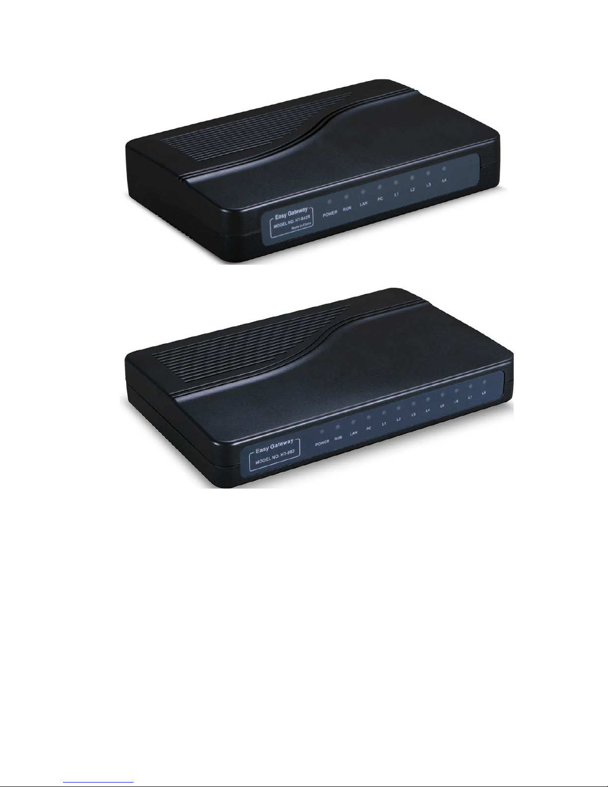
HT_842R
HT_882
1) LAN
Connect this port to an Ethernet Switch/Router, the Ethernet of a DSL modem, or
other network access equipment.
2) PC
Connect a computer or other network device to this port. (Less than 100
mid-range)
3) Power (DC24V/500mA)
Connect the 24V/500mA Adapter provided to this power jack.
4) Reset
Reset switch, use to start the device or delete the configuration quickly.
Page 8
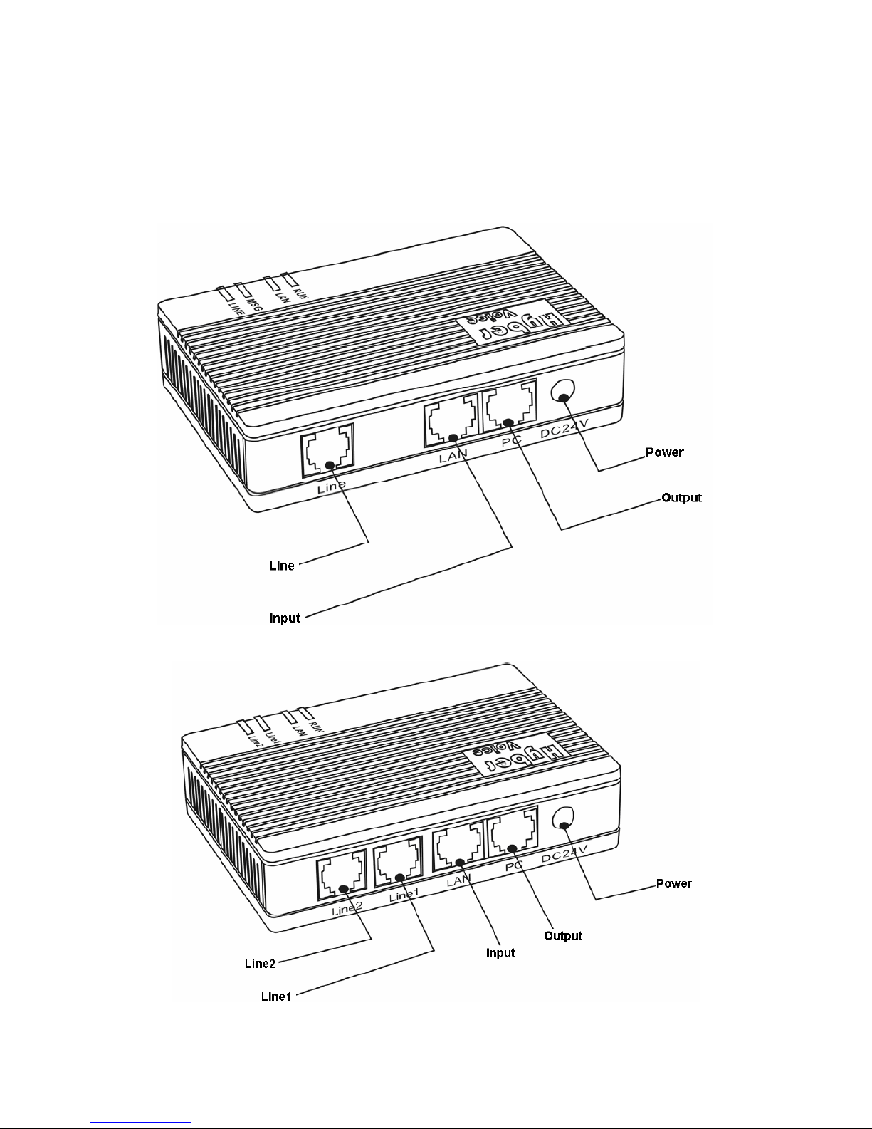
2. Connection
2.1. Interface Description:
HT-912
HT-922
Page 9
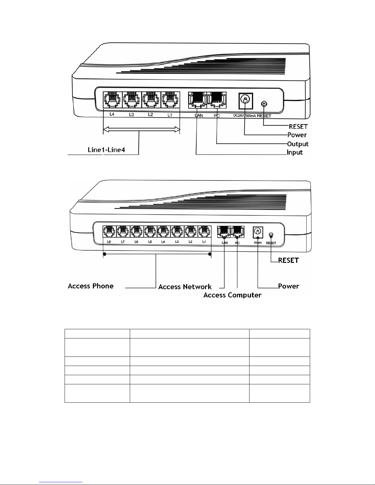
HT-842R
HT-882
Diagram 2-1
Interface Name Connect to Notes
L (1-8) FXS Output, connected to normal phone Length of line less
than 300 meters
LAN Network input, connected to Network 10/100Base T
PC Network output, connected to computer 10/100Base T
DC24V Connected to power
RESET Restore the factory configuration Press(more than 10
seconds)will ok
Page 10
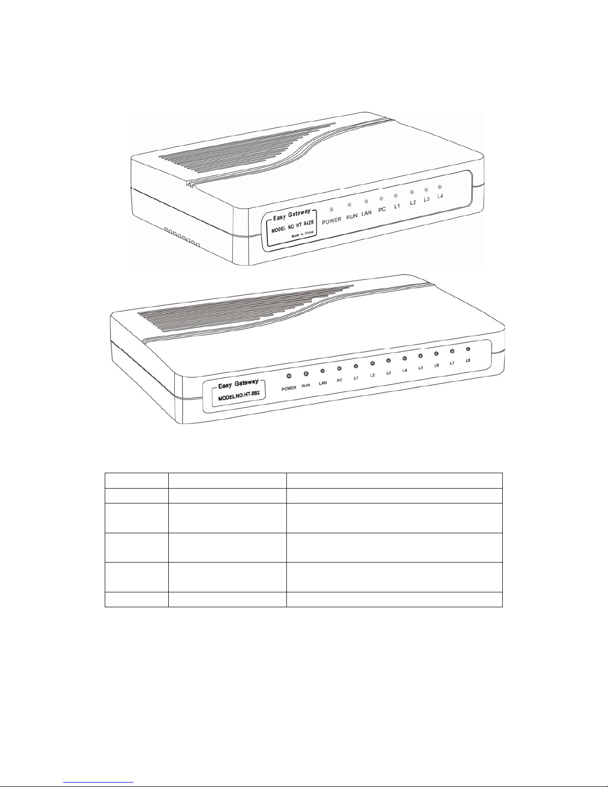
2.2. Indicator lights explanation:
Diagram 2-2
Name Explanation performance
Power Power LED Post-Long after starting
RUN Working status lights Logged, flash 250 ms; login, slow flash 500 ms;
upgrading, Continuous flashing 100 ms.
LAN LAN Network Lights Light after connect the Network, flash when
Data Transmission
PC PC Network Lights Light after connect the Network, flash when
Data Transmission
L (1-8) Line status lights Light after picking up the phone
Page 11
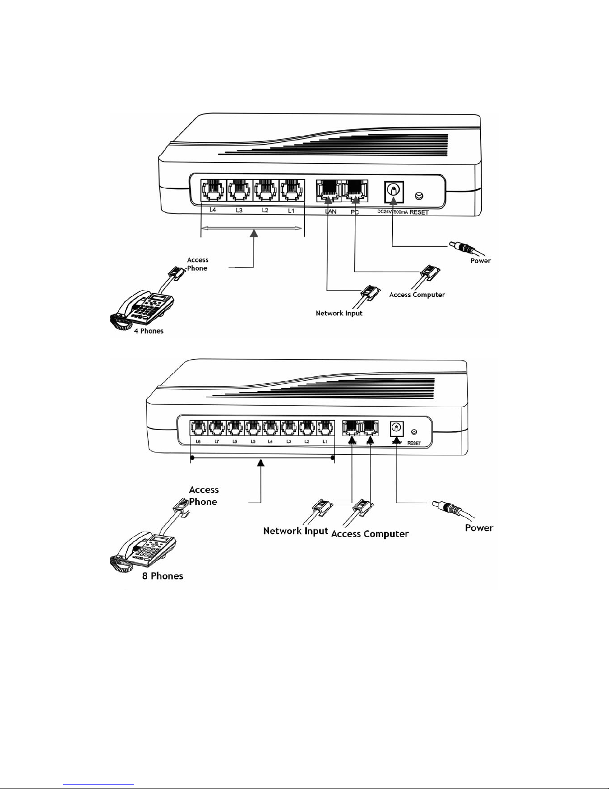
2.3. Connection diagram:
Diagram 2-3
FXS Series have a LAN port and a PC port. Please connect as follows:
1. Open the package, there are a Gateway, a power, and a cable;
2. Take out of Ethernet cable and connect to LAN port;
3. The PC supports Network share, connect to the computer or lower switch;
4. FXS is connected to normal telephone.
Make transformer output terminal.
Page 12

3. Configuration
3.1. Factory setting parameters:
Parameter Default setting Explanation
Username admin
Password admin Please remember the password
after change
LAN Network Setting DHCP
PC Network Setting Bridge mode
LAN IP *00(Chinese)
*01(English)
Press “*00” or “*01” get IP address
LAN IP Setting *03 Such as *03192*168*1*2#
Restore factory *11983185922 After input password and hear
“Toot”, then success, you just to
pull power and restart the
Gateway.
3.2. Log on to the Gateway
3.2.1. Get IP
A) Make sure that there is DHCP sever: In accordance with connection diagram
2-3,connect the Gateway and open power , see if the RUN light flash or not.
About the RUN light quick flashes 10 seconds, put up the telephone and press
*00, telephone will report IP address in Chinese; Press *01, then will report in
English.
B) Without DHCP sever in the Network: Put up the telephone and press *03+IP
address, such as “*03192*168*1*2#”, indicates that IP temporary address is
192.168.1.2. If you want to know how setting is successful, just to press *00 or
*01 and hear the IP again. Notice that the temporary IP is the same as the
PC-segment and not conflict with other Network setting. The same
PC-segment means the first three sections the number of IP must consistent,
such as 192.168.1.3 and 192.168.1.5 are the same segment, 192.168.1.3 and
192.168.2.4 are not.
Page 13

3.2.2. Open browser and input IP
After get IP or set a segment IP, open the browser (IE), and input IP on the
Address Bar.
If the connection is correct, the W eb Browser will prompt you to enter the “User
name” (admin) and “Password” (admin) as shown below.
Input the username and password, enter state page, as following figure:
Page 14

Sequence number: The Gateway factory serial number;
Software version number: FXS Series’ software version. This parameters is identified by
the system automatically, users can change by upgrading the Gateway;
Hardware model: Its line configuration can be identified by system software;
Line (1-8) Registration Status: Normal registration,show LOGIN, or, show LOGOUT.
LAN port: Shows the LAN IP;
LAN’s Hardware address: LAN’s MAC address;
PC port: Shows the PC IP;
PPPOE: Shows the status of PPPOE, Disabled or enabled;
Default route: The Gateway use;
Domain Name Server: The DNS Server of the Gateway.
3.3 Gateway Configuration
Click “Configure”, enter interface, and start to configure:
Page 15

3.3.1. User options
A) Language
Enter the language page, you can configure it. If now Chinese, you want English
page, choose “English”, then click “Save change”, that is OK.
Also you can configure it with “Language option” in the upper right corner. As figure,
click “English”.
B) Time Zone
According to special place to configure, device use Network Time Protocol obey the
information of time and date on the server, the lag will change automatically. For
example: the Pacific Standard Time is GMT-8, while Pacific daytime is GMT-7.
Page 16

Time Zone shows the place where users are, only fill it correctly, CND and billing
information can show the right time.
C) Time Server
Server address that the Gateway get Network time by Internet. The default is:
pool.npt.org.
D) Auto Provision
Choose “Enable” and fill the server IP, if service provider do not support the service,
then choose “Disable”, which make setting start-up speed fast.
E) Remote Control
Input *20# and initiate requests by Terminals device, doing this can control the
remote device. Remote control server is supported by service provider, default port
is 1920, logo terminals by SN. The address and password are the same.
As indicated in figure, fill 202.155.200.154, pick the phone and press *20#, then hear
a long tone, shows succeed. Open http://202.155.200.154:8086
, and you will see the
connected Gateway model and serial number, click “serial number”, you can
configure it.
Page 17

F) Tone Mode
It is dialing tone and ring back tone, and so on. You can choose different tone
according to different countries.
G) China Phone Code Matching
Can match all the China phone code and make sure the fastest dial time
H) Reboot Time
The Gateway will reboot within the specified time, in order to clean the equipment
cache, and make sure the device running normally.
3.3.2. Network Configuration
When you need to change the way of Network connection, you can choose
“Network Configuration” and start to configure.
Access network has 3 kinds, get IP address automatically (DHCP)、Hand Set、and
PPPOE. When choose getting IP address automatically, you just to click “DHCP”, do
not need to fill parameters.
When choose Hand Set, click “standard IP” and fill the IP address, mask and
Gateway address. When use standard IP, you should fill in “Main DNS” server-address
to get Domain Name Service, getting this address you can consult your Internet access
service providers.
Page 18

When need to use PPOE, click it, and input the Username and password.
When use PPOE, need to enable Gateway routing, so that the PC that connected
to the Gateway can connect to the Internet correctly. Change the PC Bridge Mode
into Standard IP, configure as follows:
Page 19

PC port enables standard IP, the mask 2555.2555.2555.0, after enable DHCP, the
computer that connected to the PC port can get arbitrary IP in the range of start
address and end address.
Notes: The PC IP could not exist in the same segment with the LAN, in case of
conflict.
3.3.3. Call Setting
3.3.3.1. H.323
Click “Call Settings”, expand the page, configure all the parameters:
1. Choose the terminal mode H.323
2. Fill login information: Server address, Gatekeeper address, telephone number, H.323
ID. If need to fill certification information, please click “Enable Authentication”, and
fill the certification account and password.
Page 20

Single Configure
Configure by Line
Page 21

Configure by Group
3. As indicated in Figure, when choose H.323 protocol, you should choose “H.323
Terminal”. When several lines use the same number, choose “Single server mode”,
when each line choose different numbers, choose “By wiring”. When choose “By
wiring”, each line can login to different servers.
A) H.323 telephone number
Composed by a group of decimal number, use to certain the number in the
Network. For example, 5551234 is effective number, input this number in the
bank. When login with telephone number, fill it; when login with number, you will
hear dial-tone, then dial again.
B) H.323 ID
A mode of account certification, users can fill according to the service provider.
C) Gatekeeper address
Use to find right Gatekeeper, fill the IP: 192.168.2.1 or domain: gk yourisp.com.
If your port is not the standard (1719, 1720), you can add the special port in the
back of the IP or domain, for example: login with 7300: 192.168.2.1:7300 or gk
yourisp.com:7300.
Notes: Any character of the parameters should be filled with ASCII.
D) Use authentication
Click “Enable authentication”, fill the bank in the corresponding option.
E) Dialing Rules
Please refers to “Dialing Rules”
F) Line Fax
HT-912T & HT-922T support T.38.
HT-842 & HT-882 dont support.
3.3.3.1.1 Configuration mode
The configuration mode of FXS VOIP channel: 1) Single configure; 2) Configure by line; 3)
Configure by group
Page 22

A) Single Configure: User can make several VOIP channel share the same
configuration.
B) Configure by line: Every VOIP channel can be supported service by different
providers, also login 2 or 4 telephone numbers on the same server, each number
is bundled with corresponding VOIP channel.
C) Configure by group: In this mode, each group can bundled one or several lines,
each line can exist in different groups. That is each line could login on 4 se rvers.
Notes: The special settings of 3 configuration mode refer to FXS configuration
3.3.3.1.2. Encryption
The Gateway is compatible of encryption of VOS and AVS, if need password, please
enable it.
A) VOS Signaling Encryption: Only make encryption on signaling.
B) VOS Signaling and Media Encryption: Make encryption on the signaling and media.
C) AVS Signaling Encryption: Only make encryption on signaling.
D) AVS Signaling and Media Encryption: Only make encryption on signaling.
Notes: The 4 encryption modes only effective on VOS or A VS users, if you use other
platform, you could use Firewall-penetrating technology Relay Agent by DBL.
Special details .please refer to Firewall-penetrating.
3.3.3.2. H.323 Advanced Setting
FXS Gateway’s advanced option, correspond “Advanced” and “Media”. Click
“Advanced”, the page as following:
Page 23

A) RAS Port
RAS is communications protocol of Terminal and Gatekeeper, and state
information of transferring login information, login information, broadband, and
the relationship of the 2 H.323. This option can designate the UDP of this protocol,
can be used by the router's port mapping.
B) Call signaling port (Q.931)
H.225-Q931 is call-control protocol of H.323, use to transfer the call-setting and
uninstall information between the 2 H.323. This option can designate the terminal
that receive the calling from Q.931 port, can be used by the router's port
mapping.
C) Media Control Port (H.245 Port)
H.245 is media control port of H.323. This option can designate the Terminal that
receive the calling from port connected to H.245, can be used by the router's port
mapping.
D) Quick Connect
Use to check and solve compatibility problems. If uncertain, do not choose this
option.
E) Registration Mode
Use to compatible different PBX, do not need to configure under normal
circumstances.
F) DTMF Signaling
By using DTMF, the telephone transfer phone-signal to call clearinghouse by audio
tape. That is to say, two different frequencies of sound are combined into 16 kind
of tone. Telecommunications or telecom service hotline like 1860 identifies these
special sounds by DSP, which use to certain the dial-number. DTMF has 2 styles:
Inband and Outband.
Page 24

1) Inband DTMF
This style makes the special dial-tone together with talk-tone and transfer out
without any treatment. So Inband only has one way to set DTMF signaling.
2) Outband DTMF
This style uses special methods and transfers the dial-tone to certain the
correctness. The special methods are the called protocol, such as RFC2833.
G) QOS Signaling
QOS is network quality of service and ability of higher priority service that
network supports, including dedicated broadband、control and delay jitter、packet
loss rate improvement and so on. This option can label for QOS which is
designated by call signaling packets, in order to improve the network quality of
service.
3.3.3.3. SIP Protocol
SIP (Session Initiation Protocol) is identified by IETF, use to create, change and
release the session of one or several participants. These sessions are like Internet
Multimedia Conference, IP phone or Multimedia Distribution. The session participants
could communicate by Multicast, Mesh Unicast, or mixture of the two.
If use SIP protocol, choose SIP Terminal, and enter SIP configuration page.
Single Server Mode
Page 25

Configure by Line
A) Telephone number
Use to fill numbers of this line. This number indicates that called is the only
parameter identification.
B) Display Name
When you call your friend John, then his phone will show you call.
C) SIP Proxy
Use to fill address of SIP Proxy. If your SIP Proxy is special port (is not the default
5060), you can notes in the back of IP P roxy or Domain. Such as: 192.168.2. 1:5070 or
tester.com.cn:5070.
D) SIP Registration Server
Use to register account for the Gateway, and fill the IP or Domain of SIP R egistration
Server. If your server is special port (is not the default 5060), you can notes in the
back of IP Proxy or Domain. Such as: 192.168.2.1:5070 or tester.com.cn:5070.
E) Outbound Proxy
Exist in the firewall/NAT. It is used to make signaling and stream can penetrate the
firewall.
F) Ownership of the domain
Use to manage the Domain Management Host of SIP protocol.
G) Certification ID
Use to fill the certification account that the Gateway logins on the SIP registration
server.
H) Password
Page 26

Use to fill the certification password when the Gateway logins on the SIP
registration server.
I) Dialing Rules
Please refer to “Dialing Rules”.
J) Backup Server
Use to register backup, when user have a Backup registration server, then can
choose this option. If the Backup registration server is enable, while the main server
is failure unexpectedly, the Gateway will register to the Backup server
automatically.
K) Line Fax
HT-912T/HT-922T supported T.38.
3.3.3.3.1. Configuration Mode
The configuration mode of FXS VOIP channel: 1) Single configure; 2) Configure by
line; 3) Configure by group
A) Single Configure: User can make several VOIP channel share the same
configuration.
B) Configure by line: Every VOIP channel can be supported service by different
providers, also login 2 or 4 telephone numbers on the same server, each number
is bundled with corresponding VOIP channel.
C) Configure by group: In this mode, each group can bundled one or several lines,
Page 27

each line can exist in different groups. That is each line could login on 4 se rvers.
Notes: The special settings of 3 configuration mode refer to FXS configuration
3.3.3.3.2. SIP Advanced Configuration
SIP advanced option, correspond “Advanced” and “Media”. Click “Advanced”
and “Media”, the page as following:
A) Signaling Port
SIP local port is the local UDP port, use to communicate with SIP proxy or other
SIP users.
B) NAT Keep
Use to keep the port when NAT communicate with SIP signaling, its unit is
seconds.
C) DTMF Signaling
By using DTMF, the telephone transfer phone-signal to call clearinghouse by audio
tape. That is to say, two different frequencies of sound are combined into 16 kind
of tone. Telecommunications or telecom service hotline like 1860 identifies these
special sounds by DSP, which use to certain the dial-number. DTMF has 2 styles:
Inband and Outband.
1) Inband DTMF
This style makes the special dial-tone together with talk-tone and transfer out
without any treatment. So Inband only has one way to set DTMF signaling.
2) Outband DTMF
This style uses special methods and transfers the dial-tone to certain the
correctness. The special methods are the called protocol, such as RFC2833.
D) QOS Signaling
QOS is network quality of service and ability of higher priority service that
network supports, including dedicated broadband、control and delay jitter、packet
loss rate improvement and so on. This option can label for QOS which is
designated by call signaling packets, in order to improve the network quality of
service.
Page 28

E) Signaling Encryption
a ) None: Not encrypted.
b) RC4: This is a variable key length stream encryption algorithm clusters, its
S-box is random, generally 256 bytes.
c) Fa st: a long delay for high-speed networks, TCP Congestion Control Protocol,
require server-side support.
d) VOS: For VOS users.
e) AVS: For AVS users.
f) N2C: For N2C users.
g) ECM: For ECM users.
h) ET263: For ET263 users.
F) NAT Signaling Penetration.
Special configurations please refer to firewall.
3.3.3.3.3. Media Advanced Configuration
Media Advanced Configuration Aimed at the gateway RTP media stream part of the
advanced configuration options, click “Media” in the “call setting”.
A) KTP Port (range)
Use to designate the UDP of Real-Time Media Transfer Protocol (RTP), used with
the router’s port mapping.
Notes: The terminal use several pairs of RTP, its value is the port range, such
as (5500-5520).
B) RTP Packet Length
The default time length of each wet packet is 20ms. Use to designate the size of
media-packet, the unit is sampling time ms.
C) Jitter delay processing mode
Use to designate Jitter delay buffer algorithm model. Adaptive mode is the best,
other modes are used for test, please do not use in the practical action.
D) Media Encryption
Page 29

a) None: Not encrypted.
b) RC4: This is a variable key length stream encryption algorithm clusters, its
S-box is random, generally 256 bytes.
c) ET263: For ET263 users.
E) Media QOS
QOS is network quality of service and ability of higher priority service that
network supports, including dedicated broadband、control and delay jitter、packet
loss rate improvement and so on. This option can label for QOS which is
designated by call signaling packets, in order to improve the network quality of
service.
F) Speech coding and sequencing
【√】indicate that coding is available, UP and DOWN on the currently selected
voice compression coding to adjust priorities
3.3.3.4. Firewall Traversal
In the advanced configuration of call settings, signal and media each has
firewall configuration.
3.3.3.4.1. H.323 Signaling NAT Traversal
There are four styles as follows:
Page 30

A) None
Select None to turn off this feature.
B) Nat Citron
Citron is a dedicated firewall penetration agreement for GNUGK.
C) Port Transparent/DMZ
Port Transparent refers that put network port of the LAN into computer or inside of
the LAN. The actual servers allow external users enjoy the servers of internal
server(FTP、HTTP、Telnet) .
Port Transparent includes the Gateway address and response server address.
Gateway is communications equipment that connect two different networks,
response to the server is standard service equipment that perform ECHO protocol.
D)Relay proxy
Relay proxy is a proprietary NAT traversal technology. It includes relay proxy
server address, port, username, and password.
Relay proxy makes encryption on the Gateway’s communication, this function need
the support of DBL. technology.
3.3.3.4.2. SIP Signaling NAT Traversal
SIP Signaling NAT Traversal h as 3 kinds:
Page 31

A) None
Select None to disable this feature.
B) STUN (RFC 3489)
STUN (Simple Traversal of UDP (User Datagram Protocol) through NATS
(Network Address Translators)) is a network protocol allowing a client behind a
NAT (or multiple NATS) to find out its public address, the type of NAT it is behind
and the internet-side port associated by the NAT with a particular local port.
Select STUN (RFC 3489) to use a STUN server for Signaling NAT Traversal. Enter the
IP address or the domain name of the STUN server to be used.
C) Relay Proxy
Relay proxy is a proprietary NAT traversal technology. Please consult your
service provider for more information. It includes relay proxy server address, port,
username, and password.
Relay proxy makes encryption on the Gateway’ s communication, this function need
the support of DBL. technology.
Currently, the following 3 kinds of packaging mechanism are supported.
3.3.3.4.3. Media NAT Traversal
Similar to Signaling NAT Traversal, this feature allows media packets (RTP) to be
routed properly in various network environments.
Page 32

A)NONE
Select None to disable this feature.
B) Port Transparent/DMZ
Port Transparent refers that put network port of the LAN into computer or inside of
the LAN. The actual servers allow external users enjoy the servers of internal
server(FTP、HTTP、Telnet).It contains Gateway address and the responding to the
server's address. Gateway is communications equipment that connect two different
networks, response to the server is standard service equipment that perform ECHO
protocol.
C)STUN(RFC3489)
STUN (Simple Traversal of UDP (User Datagram Protocol) through NATS (Network
Address Translators)) is a network protocol allowing a client behind a NAT (or
multiple NATS) to find out its public address, the type of NAT it is behind and the
internet-side port associated by the NAT with a particular local port.
Select STUN (RFC 3489) to use a STUN server for Signaling NAT Traversal. Enter the IP
Address or the domain name of the STUN server to be used.
D) Relay Proxy
Relay proxy is a proprietary NAT traversal technology. Please consult your service
provider for more information.
Currently, the following 3 kinds of packaging mechanism are supported:
¾ Mode 1: The media uses UDP packets and (or) encrypt with multiple UDP port;
¾ Mode 2: The media uses UDP packets and (or) encrypt with single UDP port;
¾ Mode 3: The media uses TCP packets and (or) encrypt (UDP over TCP).
3.3.4. Phone Settings
A) PhoneBook Function: Configure *50, you can use PhoneBook, if you need to dial
first number on PhoneBook, press *501#.
B) FXS 48v Standby: Use when standby.
Page 33

C) Billing Support: Enable the call hold, with the HOLD key to use.
3.3.5. Save Changes
When you finish settings, click “save change” save all the settings.
3.3.6. Abandon changes
If your new settings are not saved, you can clean all the unsaved new parameters.
Page 34

4. Tools
4.1. Online Upgrade
Page shows current version information, input upgrade address, click start, wait
after upgrade and start again. When the page shows “Upgrade successful”, click
“OK”.
Notes: Please keep in touch with the company’s technology support, in case
that get the latest information and upgrade address.
4.2. Change Password
Include “Ordinary user-level” (user) and “Administrator Class” (admin), input the new
password two times, click “change” is ok.
4.3. Restore factory settings
If you make sure that clean all configurations, click “OK”, wait start again. If not,
Page 35

click “Cancel”, back to current page.
Notes: All the users’ personal configur ation include new changed password will be
cleaned.
You also finish these by pressing “RESET” in a long time.
4.4. Reboot the system
If you are sue to reboot the system, click “OK”, if not, then click “Cancel”, back
to current page. Point the “RESET” gently with Small needle-like objects, the Gateway
will reboot.
Notes: Press the “RESET” will lead HTM_442 restore factory settings, all the
parameters that users configure will be cleaned.
5. Dialing Rules
Dialing rules make users configure number rules flexible, its expressions are:
Prefix: Action | Prefix: Action
Prefix is in front of the called number. “:” is Actions associated with Fu. “|”is
Separator, separates different prefix. Matching sequence is longest match.
For example: the Gateway is connected to extension line, fill “0755:-0755+9,|
07551:-0755” in PSTN, which indicates that dial 0755 Gateway, deleted (-0755)
dial “9” to get outside line, then dial the remaining numbers after 0.5 seconds. If
Dial 07551, which indicates that you dial inside number, the Gateway will dial the
extension number.
5.1. Basic rules of grammar
1. Rules can be separated by “|”, such as “00:-00|0:-0+86|:+86755“
2. Rules are matched by Sit-to-right, when encounter appropriate one, end the
match immediately, or continue next one.
3. Syntax rules is “AA: -aa+bb”,such as “0:-0+86”,“AA” is the matching numbers,
Page 36

in the back of the colon is the corresponding concrete operation. If succeed, minus
“aa” and “bb”, if not, continue next one. If the back of colon without operation,
such as“00:”, do not make any operation and exit. If in front of the colon without
string, such as “:+86755”, do operation.
4. Dialing rules have no range, its syntax rule is “[A-B]A:-aa+bb” or “A[A-B]:-aa+bb”.
For example: The range of 2 to 8 is that: “[2-8]:-aa+bb”or13 to 15 is
“1[3-5]:-aa+bb”.
Such as:
1. Rules: “0:|:0755”.
a. Input“02083185711”,output“02083185711”;
b. Input“83185700”,output“075583185700”.
2. Rules: “00:-00|0”-0+86|:+86755“.
a. Input“008522343318”,output“8522343318”;
b. Input“02083185711”,output“862083185711”;
c. Input“83185700”,output“8675583185700”.
3. Rules: “00:|0:-0+086|:+0086755”.
a. Input“008522343318”,output“008522343318”;
b. Input“02083185711”,output“00862083185711”;
c. Input“83185700”,output“008675583185700”.
4. Rules:“0:|1 [3-9]:+0|[2-8]:+0755|:+0755”.
a. Input“076322343318”,output“076322343318”;
b. Input“13044557766”,output“013044557766”;
or“13644557766”,output“013644557766”
c. Input“23185700”,output“075523185700”.
Or“73185700”,output“075573185700”
5.2. With a limited number of digit dialing rules
If you want to do restriction on every phone number, the dialing number of HT-3040
is configured as “AAXXXXXXX:-aa+bb”,AAXXXXXX is the matched number and its length.
Other numbers are instead of “X” or “x” except of “AA”; In the back of colon is the
corresponding concrete operation of this number.
The configurations as following:
Like the above 3. “00:|0:-0+0086|:+0086755”.
Change like this “00:|0:-0+0086|[1-8]xxxxxxx:+0086755”.
The length is 8 if you dial the number that the beginning are 1 to 8, the Gateway
will dial the number automatically add “0086755”. Or:
“0:|13:+0|:+0755”
Then add “0”in front of mobile number, and“0755”in front of city telephone
number.
Change like this “0:|13 [0-9] xxxxxxx:+0755”
Page 37

This rule is like above, but the length of mobile number is limited 11.
As indicated above, the length of city telephone number is limited 8. 13[0-9]
xxxxxxxx and [1-8] xxxxxxx indict 130xxxxxxxx to 139xxxxxxxx and 1xxxxxxx
to 8xxxxxxxx.
Notes: After using the median number of definitions, the length of number is longer than
the definition, then the superfluous numbers will be discarded, for example:
“0:|13[0-9]xxxxxxxx:+0|[1-8]xxxxxxx:+0755”
The number is 075588990011.
6. Understand More
6.1. Gateway Initialization
When forget the password, users can press (more than 10 seconds) RESET or
input *11983185922, restore factory configuration.
6.2. Advanced Configuration
There are many configuration option in the advanced configuration, such as
Agent Services, Speech Coding sequence and so on, if you familiar with our product,
you can configure directly, if not, please view our detailed description, or search our
technology support: support@at338.com
6.3. Notes
a) When use the Gateway, please notice that outside whether overhead line or
not, take measures of lightning (purchase Lightning All, or put Lightning Terminal on
the Wire frame).
b) The Gateway has a certain degree of heat, please ventilation and do not
cover flammable liquids.
c) The Gateway has line detection, if line is not connected well, then break
when you dial the Gateway.
d) The Gateway has fat switch polarity detection function, which can prevent
line hanging death and improve the Gateway’s time to hang up.
e) When device is upgrading, please notice that absolutely you can not tur n
off the power, or, the device will scrap!
 Loading...