

Page 1

User Manual
FCC ID: 2AKS8DX-BT18
Model Name: DX-BT18
Shenzhen DX-SMART Technology Co Ltd.
DX-BT18 Dual Bluetooth Module
Page 2

Table Of Contents
1、Overview .................................................................................................................14
2、Module Default Parameters .................................................................................14
3、Application Area....................................................................................................14
Power consumption parameters
4、
5、Transparent Transmission Parameters ................................................................15
6、Module Pin Description And Minimum Circuit Diagram..................................16
...................................................................15
7、Pin Function Description ......................................................................................17
8、Detailed Description Of Function pins.................................................................18
9、Dimensions ...........................................................................................................18
LAYOUT
10、
11、AT COMMAND...................................................................................................19
11.1 Test Instructions .....................................................................................21
11.2 Get The Software Version……………...................................................21
11.3 Set/Query Module Bluetooth MAC……...............................................21
11.4 Set/Query Device Name.........................................................................21
11.5 Set/Query - Serial Port Baud Rate..........................................................22
11.6 Set/Query Pairing PIN............................................................................22
11.7 Query - UUID………………….............................................................23
Precautions
...................................................................................19
11.8 Set -Service UUID..................................................................................23
11.9 Set- NOTIFY UUID\ WRITE UUID.....................................................24
11.10 Set -WRITE UUID ..............................................................................24
11.11 Disconnect The Llink……....................................................................24
12、Contact Us...........................................................................................................24
Page 3
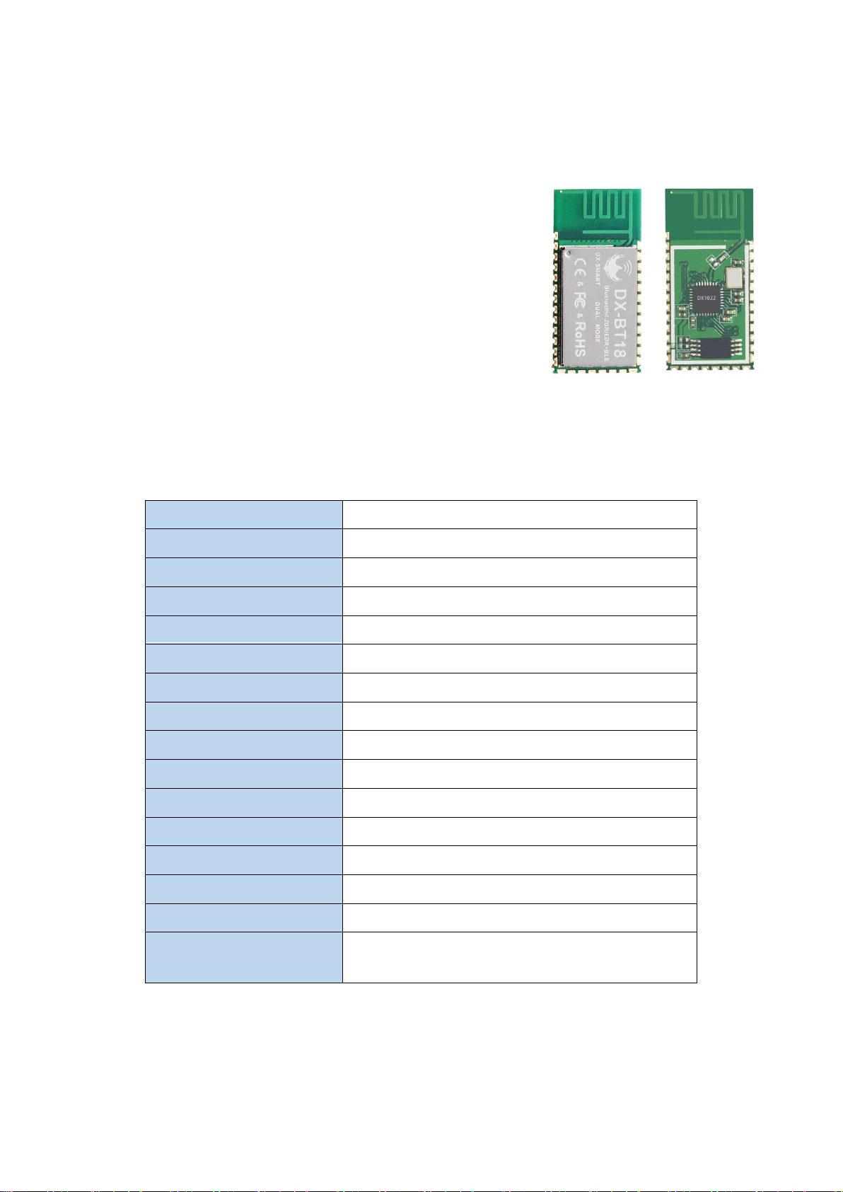
1.Overview:
DX-BT18 dual-mode Bluetooth module is a dual-mode
Bluetooth module (Dual-Mode) that is specially designed for
smart wireless data transmission by Shenzhen DX-SMART
Technology Co., Ltd. and follows the Bluetooth 4.2 standard
protocol.
DX-BT18 module applies to wireless data transmission
field, uses BT4.2 Bluetooth chip + PCB printed antenna
design, SOC chip embedded BT4.2 Dual-Mode protocol stack,
supports data transmission of Windows, Linux, Android, iOS
and other systems And applications, with industrial design,
transmission distance, data stability, simple operation, high
cost performance and technology leading edge.
2.
Module default parameters
Bluetooth Protocol Bluetooth 4.2 BR/EDR+BLE -
Working Frequency 2402-248MHz
Communication Interface UART
Power Supply 3.3V
Communication distance 30-40M (Open and unobstructed environment)
Physical Dimension 27mm x 13mm x 2.35 mm
Bluetooth Authentication ROHS REACH FCC
Bluetooth Name DX-BT18
Pairing Code 1234 (The SPP agreement is valid)
Serial Port Parameters
Service UUID FFE0
Notify\Write UUID FFE1
Write UUID FFE2
:
9600、8 data bits、1 stop bit、No check、No flow control
Storage temperature
Work temperature
Custom requirements
MIN:-40℃ - MAX:+140℃
MIN:-20℃ - MAX:+85℃
If you have other special function requirements, you
can contact us to customize the module.
Page 4

3.Application area:
DX-BT18 module supports BT4.2 SPP standard protocol, which can be paired with all
Bluetooth-enabled desktop computers, notebooks, Andriod mobile phones and Bluetooth main
module to achieve bidirectional data transmission and receiving; DX-BT18 module supports
BT4.2 BLE protocol at the same time , Can connect directly with iOS device with BLE Bluetooth
function, support background program resident operation.
Successful application of BT18 module:
※ Bluetooth wireless data transmission;
※ mobile phones, computer peripherals;
※ hand-held POS devices;
※ Medical equipment wireless data transmission;
※ smart home control;
※ car detection OBD equipment;
※ Bluetooth printer
※ Bluetooth Remote Control Toy
※ Anti-lost device, LED light control
4.Power consumption parameters:
DC-DC Average Current Unit
Discoverable 4.4 mA
Connected (BLE) 3.8 mA
Connected (SPP) 12 mA
5.Transparent transmission parameters
SPP data throughput:
Android ->BT18 -> UART UART ->BT18 -> Android BAUD
14400 bytes/s 7500 bytes/s 115200
BLE data throughput:
IPhone 6 ->BT18 -> UART UART ->BT18 -> IPhone 6
Baud rate 115200 Baud rate
Connection interval (ms) 15 Connection interval (ms)
115200
15
APP Serial packet size (bytes) 300 Serial packet size (bytes)
Transmission interval (ms) 20 Transmission interval (ms)
Throughput (bytes/s) 5000 Throughput (bytes/s)
300
50
5040
Page 5
Characteristic Write method
Note: This table parameter is for reference only and does not represent the maximum data
throughput that the module can support.
Write without
Response
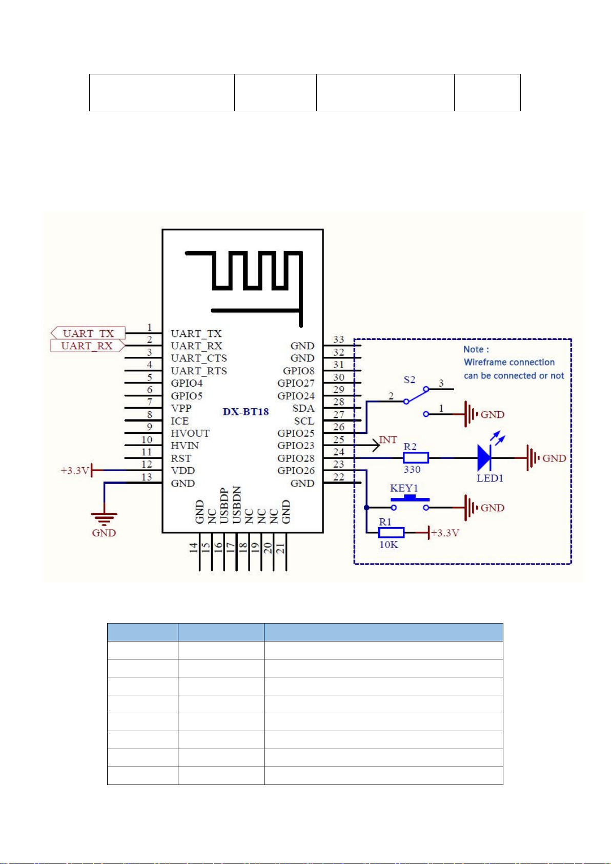
6.Module pin description and minimum circuit diagram:
7.Pin function description:
Pin number Pin name Pin description
1
2
3
4
5
6
7
8
UART_TX Serial data output
UART_RX Serial data input
UART_CTS Vacant
UART_RTS Vacant
GPIO4 Programmable input and output port
GPIO5 Programmable input and output port
VPP
ICE
Firmware upgrade port
VPP
Page 6

9
HVOUT Programmable input and output port
10
11
12
13
14
15
16
17
18
19
20
21
22
23
24
25
26
27
HVIN Vacant
RESETB Low level reset, at least 5ms
VCC Power supply V3.3
GND GND
GND GND
NC
USBDP
USBDN
NC
NC
NC
NC Vacant
NC Vacant
NC
NC
GND GND
GND GND
GPIO26 Disconnect pin (200ms low electrical pulse off)
GPIO28
GPIO23
GPIO25
LED light pin (unconnected flashing, connection
is always on)
Bluetooth connection indicator (not connected
low, connection high)
AT command switch pin (low AT command
mode)
SCL NC
28
29
30
31
32
33
SDA
GPIO24 Programmable input and output port
GPIO27 Programmable input and output port
GPIO28 Programmable input and output port
GND GND
GND GND
NC
8.Detailed description of function pins:
1、 P24 pin (GPIO28): LED indicator pin
·Used to indicate the status of the Bluetooth module. Correspondence between the LED
flashing mode and the Bluetooth module status is shown in the following table:
LED display
Uniformly slow flashing (800ms-on, 800ms-off) standby mode
always brigh
2. P26 pin (GPIO25): AT command switching pin
Pin status Module status
Module status
Connection Status
Connect to GND Enter AT command mode
Page 7

NC Module enters transparent mode
3. P25 pin (GPIO23): Connection status indicator
Pin status Module status
Low output standby mode
Output high Connection Status
4. P23 pin (GPIO26): Connect interrupt pin (module is in valid connection state)
Pin status Module status
No action Connection Status
Input 200ms low level pulse Interrupt connection, module enters standby
9.Dimensions:
10.LAYOUT
Precautions:
The DX-BT18 dual-mode Bluetooth module works in the 2.4G wireless band. It should try to
avoid the influence of various factors on the wireless transceiver. Pay attention to the following
points:
1. The product shell surrounding the Bluetooth module to avoid the use of metal, when using
part of the metal shell, should try to make the module antenna part away from the metal part.
2. The internal metal connecting wires or metal screws of the product should be far away from
the antenna part of the module.
3. The antenna part of the module should be placed around the PCB of the carrier board. It is
not allowed to be placed in the board and the carrier board under the antenna is to be milled empty.
Page 8

The direction parallel to the antenna does not allow copper to be laid or routed. It is also a good
choice to directly expose the antenna part out of the carrier board.
4. It is recommended to use insulating material for isolation at the module mounting position
on the substrate. For example, put a block of screen printing (TopOver Lay) at this position.
11. AT COMMAND
1. When sending AT commands, you need to pull module P26 low to enter the AT command
mode. At other times, the commands do not respond.
2. AT command, which belongs to the character line instruction, is parsed according to the line
(AT command must be returned by carriage return or \r\n, hexadecimal number is 0D0A)
3. The AT command only supports uppercase. The instruction prefix is AT+ and can be divided
into parameter setting instructions and read instructions.
4. Set the instruction format: AT+<CMD>=<PARAM> The operation succeeds.
Return:+<CMD>=<PARAM>\r\n OK\r\n Fail Back:ERR\r\n
5. Read instruction format:
AT+<CMD>? Operation succeeds: +<CMD>=<PARAM>\r\nFailed to return ERR\r\n
6. instruction error or not support, return ERR\r\n
AT
com
man
d
form
at
exam
ple
(figu
re 1
is AT
test
com
man
Page 9

d, Figure 2 is to change the Bluetooth name to 1234):
1、Test instructions:
Page 10

Function Command Response Description
Test instructions
AT+TEST\r\n \r\n OK\r\n
2、Get The Software Version:
Function Command Response Description
Query version number
AT+VERS?\r\n +VERS=<version>\r\n
OK\r\n
<version > Software
version number
Note: The version will be different depending on different modules and customization
requirements.
3、Set/Query Module Bluetooth MAC:
Function Command Response Description
Query module MAC
address
Set the module MAC
AT+ADSS?\r\n +ADSS=<addr>\r\n <addr> 12-bit MAC
AT+ADSS=<LA
address code
+ADSS=<addr>\r\n
address
DDR>\r\n
OK\r\n
Note: The SPP and BLE Bluetooth address codes of the module are the same address code.
4、Set/Query Device Name:
Function Command Response Description
Query Module device
Name
Set the module device
name
AT+NAME?\r\n +NAME=<name>\r\n
AT+NAME=<na
me>\r\n
+NAME=<name>\r\n
OK\r\n
<name> device Name,
Up to 19 bytes
Default NAME:BT18
Note: The Bluetooth names of the module's SPP and BLE are the same. Each time the name is
changed, the names of the SPP and BLE are the same.
Example:
1. Send Settings:
AT+NAME=DX-BT18\r\n ——Set module device name:“DX-BT18”
return:
+NAME=DX-BT18\r\n ——Set module device name:“DX-BT18” successed
Page 11

OK\r\n
2. Send inquiry:
AT+NAME?\r\n ——Query module device name
return:
+NAME=BT18r\n ——Return module device name:“ BT18”
5、Set/Query - Serial Port Baud Rate:
Function Command Response Description
Query module baud AT+BAUD?\r\n +BAUD=<baud>\r\n <baud> Baud rate
Set the module baud AT+BAUD=<ba
ud>\r\n
+BAUD=<baud>\r\n
OK\r\n
corresponding serial
number 1:9600
2:19200
3:38400
4:115200
Default BAUD:1(9600)
Note: The module must be re-powered after setting the baud rate, enabling the new baud rate
for data communication and AT command resolution.
Example: Setting the Serial Port Baud Rate: 38400
1. Send Settings:
AT+BAUD=3 \r\n
return:
+BAUD=3\r\n
OK\r\n
2. Send inquiry:
AT+BAUD?\r\n
return:
+BAUD=3\r\n
OK\r\n
6、Set/Query Pairing PIN:
Function Command Response Description
Query module SPP
pairing code
AT+PIN?\r\n +PIN=<pin>\r\n <pin> pairing PIN
Default PIN:1234
Page 12

Set module SPP pairing
AT+PIN=<pin>\r
+PIN=<pin>\r\n
code
\n
OK\r\n
7、Query—UUID:
Function Command Response Description
Query module UUID AT+UUID?\r\n +UUID=<service>,<noti
fy>,
<write>\r\n
<service> service
UUID
<notify> notify UUID
<write> write UUID
NOTE:Module default UUID: SERVICE UUID FFE0, NOTIFY UUID FFE1,WRITE UUID
FFE2 (When setting UUID, the last two bits need to be swapped with the first two bits)
Example:
1. Send Settings:
AT+UUID?\r\n ——Query module UUID
return:
+UUID= e0ff,e1ff,e2ffr\n
OK\r\n
8、Set—Service UUID:
Function Command Response Description
Query service UUID AT+SERV=<serv
ice>\r\n
+
=<service>\r\n
SERV
<service> service
UUID
Example:Set the service UUID to: FE01 (When setting, the last two bits need to be swapped
with the first two bits)
1. Send Settings:
AT+SERV =01FE \r\n
return:
+SERV=01fe r\n
OK\r\n
9、Set—NOTIFY UUID\ WRITE UUID:
Function Command Response Description
SET NOTIFY UUID AT+NOTIFY=< +SERV=<notify>\r\n <notify> notify UUID
Page 13

notify >\r\n OK\r\n
Note: This channel is NOTIFY and WRITE (It can be read or written)
Example:Set the NOTIFY UUID to: FE02(When setting, the last two bits need to be swapped
with the first two bits)
1. Send Settings:
AT+NOTIFY=02FE \r\n
return:
+NOTIFY=02fe r\n
OK\r\n
10、Set—WRITE UUID:
Function Command Response Description
Set WRITE UUID AT+WRITE?=<n
otify >\r\n
11、Disconnect The Link:
Function Command Response Description
Disconnect the link AT+DIS?\r\n \r\n OK\r\n
+WRITE?=<write>\r\n
OK\r\n
<write> write UUID
You can disconnect the
module when the
module is connected
12.Contact us
Shen Zhen DX-SMART Technology Co., Ltd.
Address:511 ,Building C, Yuxing Technology Park, Yuxing Chuanggu, Bao'an District, Shenzhen,
China
Tel: 0755-2997 8125
Fax: 0755-2997 8369
Website: http://www.szdx-smart.com/
Page 14

Single Module
FCC Statement
This device complies with part 15 of the FCC Rules. Operation is subject to the following two
conditions:
(1) This device may not cause harmful interference, and
(2) this device must accept
any interference received, including interference that may cause undesired operation.
Any Changes or modifications not expressly approved by the party responsible for compliance
could void the user's authority to operate the equipment.
The device has been evaluated to meet general RF exposure requirement. The device can be
used in portable exposure condition without restriction.
If the FCC identification number is not visible when the module is installed inside another device,
then the outside of the device into which the module is installed must also display a label
referring to the enclosed module. This exterior label can use wording such as the following:
“Contains Transmitter Module FCC ID: 2AKS8DX-BT18 Or Contains FCC ID: 2AKS8DX-BT18”
When the module is installed inside another device, the user manual of the host must contain
below warning statements;
1. This device complies with Part 15 of the FCC Rules. Operation is subject to the following two
conditions:
(1) This device may not cause harmful interference.
(2) This device must accept any interference received, including interference that may cause
undesired operation.
2. Changes or modifications not expressly approved by the party responsible for compliance
could void the user's authority to operate the equipment.
The devices must be installed and used in strict accordance with the manufacturer's instructions
as described in the user documentation that comes with the product.
Any company of the host device which install this modular with Single modular approval should
perform the test of radiated emissionand spurious emission according to FCC part 15C : 15.247
and 15.209 requirement,Only if the test result comply with FCC part 15C : 15.247 and 15.209
requirement,then the host can be sold legally.
 Loading...