

Page 1
Product Specification
Reversion v1.0
Date 2017-03-14
Model Name
Product Name
ENGINEER
ENGINEER
联系人:邓海兵 MO:13662644686
BL-M7603NU4
IEEE 802.11b/g/n (2T2R) WLAN USB Module
Blink Approve Field
QC
Customer Approve Field
QC
MANUFACTORY
SALES
PURCHASING
0
PDF pdfFactory Pro www.fineprint.cn
Page 2

Content
Content ................................................................................................................................................... 1
1. General Description .............................................................................................................................. 2
2. Applications ......................................................................................................................................... 2
3. Product Specification ............................................................................................................................ 2
3.1 Function Block diagram .............................................................................................................................. 2
3.2 Electrical and Performance Specification .................................................................................................. 2
3.3 DC Characteristic ........................................................................................................................................ 3
3.4 RF Characteristic ........................................................................................................................................ 4
3.5 Product Photo ............................................................................................................................................ 5
3.6 Mechanical Specification ........................................................................................................................... 5
3.7 ProductPinDefinition .................................................................................................................................. 6
4. Supported platform .............................................................................................................................. 7
5.Typical ApplicationCircuit-------------------------------------------------------------------------------------------8
6. Package information ............................................................................................................................ 9
7. Typical Solder Reflow Profile ................................................................................................................ 9
8. Precautions for use ............................................................................................................................ 10
1
PDF pdfFactory Pro www.fineprint.cn
Page 3
1. General Description
BL-M7603NU4 is a highly integrated Wi-Fi single chip which support 300 Mbps PHY rate. It fully complies with
IEEE802.11n and IEEE802.11b/g standard, offering feature-rich wireless connectivity at high standard, and
delivering reliable, cost-effective throughput from an extended distance.
Optimized RF architecture and baseband algorithms provide superb performance and lower power consumption.
Intelligent MAC design deploys a high efficient DMA engine and hardware data processing accelerators which
offloads the host processor.
2. Applications
MID, networking camera, STB GPS, E-book, Hard disk player, Network Radios, PSP and other device
which need be supported by wireless networking.
3. Product Specification
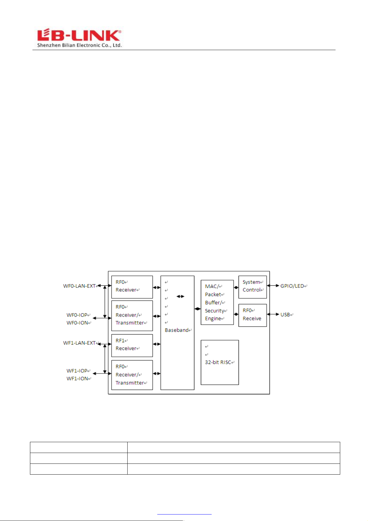
3.1 Function Block diagram
Figure 1 MT7603U block diagram
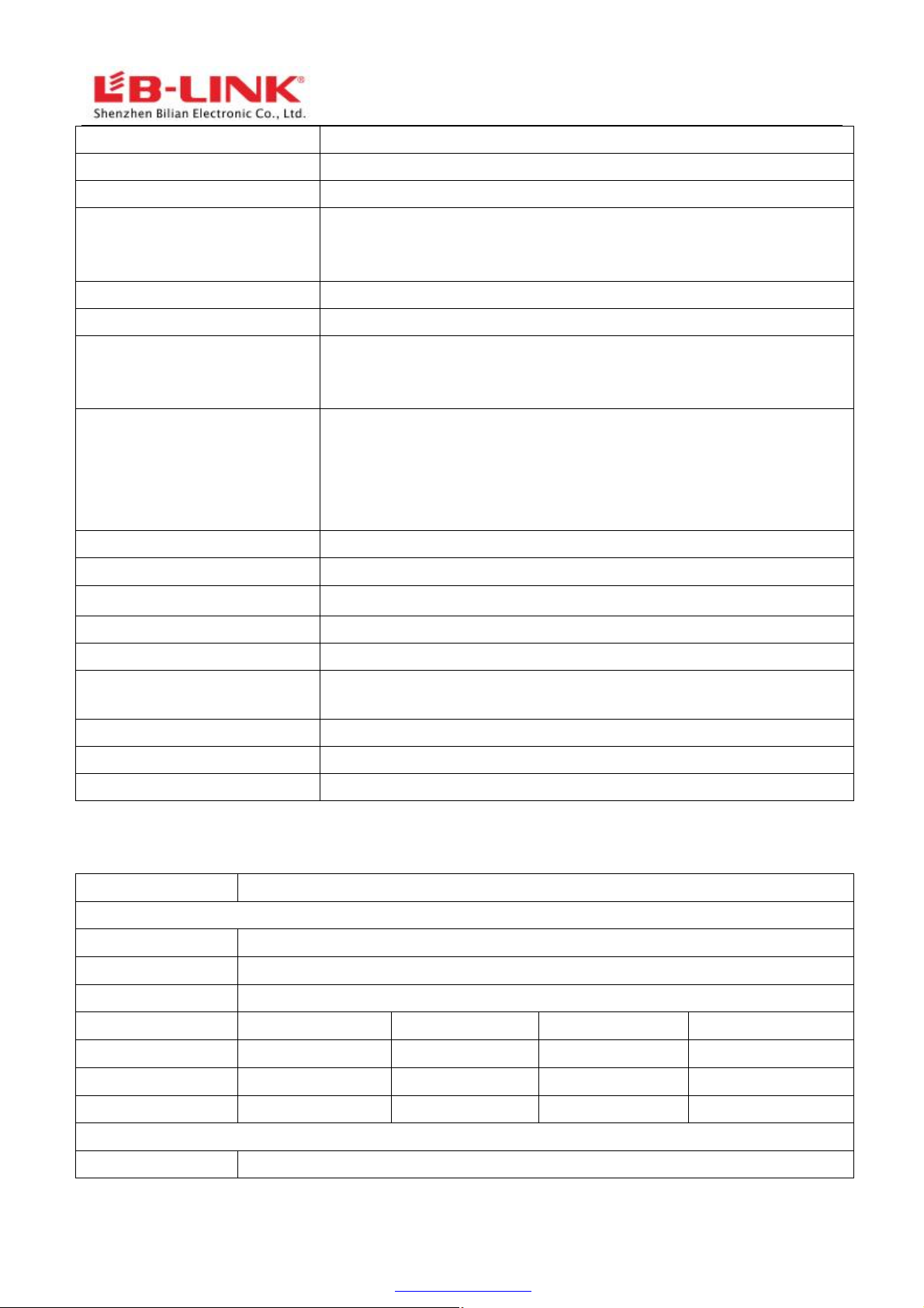
3.2 Electrical and Performance Specification
Item Description
Product Name BL-M7603NU4
Major Chipset MT7603U
2
PDF pdfFactory Pro www.fineprint.cn
Page 4
Host Interface USB2.0
Standard IEEE 802.11b, IEEE 802.11g,IEEE 802.11n
Frequency Range
Modulation Type
Working Mode
Data Transfer Rate
Spread Spectrum
Sensitivity @PER
RF Power
Antenna type Connect to the external antenna through the IPEX connector
The transmit distance
Dimension(L*W*H) 27x 17.7x 2.0mm (LxWxH)
2.4GHz~2.4835GHz
802.11b: CCK, DQPSK, DBPSK
802.11g: 64-QAM,16-QAM, QPSK, BPSK
802.11n: 64-QAM,16-QAM, QPSK, BPSK
Infrastructure, Ad-Hoc
1,2,5.5,6,11,12,18,22,24,30,36,48,54,135,300 Mbps(self-adapting)
IEEE 802.11b: DSSS (Direct Sequence Spread Spectrum)
IEEE 802.11g/n:OFDM (Orthogonal Frequency Division
Multiplexing)
1M: -94dBm@8%PER
9M: -90dBm@10%PER
11M:-88dBm@8%PER
54M:-74dBm@10%PER
135M:-68dBm@10%PER
14.71dBm@11b, 14.68dBm@11g , 14.93dBm@11n
Indoor 100M, Outdoor 300M, according the local environment
Power supply 3.3V +/-0.2V
Power Consumption standby mode 65mA@3.3V ,
Working mode 245mA@3.3V
Clock source 40MHz
Working Temperature -10°C to +50°C
Storage temperature -40°C to +70°C
3.3 DC Characteristic
Terms Contents
Specification : IEEE802.11b
Mode DSSS / CCK
Frequency 2412 – 2484MHz
Data rate 1, 2, 5.5, 11Mbps
DC Characteristics
TX mode
Rx mode
Sleep mode
Specification : IEEE802.11g
min
480
91
58
Typ max unit
650 750 mA
100 105 mA
60 65 mA
Mode
OFDM
3
PDF pdfFactory Pro www.fineprint.cn
Page 5

Frequency 2412 - 2484MHz
Data rate 6, 9, 12, 18, 24, 36, 48, 54Mbps
DC Characteristics
TX mode
Rx mode 95
Sleep mode 58
min Typ max
unit
170 230 480 mA
105 109 mA
60 65 mA
Specification : IEEE802.11n
Mode OFDM
Frequency 2412 - 2484MHz
Data rate 6.5, 13, 19.5, 26, 39, 135,300Mbps
DC Characteristics
min
Typ max unit
TX mode 165 220 450 mA
Rx mode
Sleep mode
95
58
105 110 mA
60 65 mA
4
PDF pdfFactory Pro www.fineprint.cn
Page 6

3.4 Product Photo
3.5 Mechanical Specification
Module dimension: Typical (W x L x H): 27.0mmx17.7mmx2.0mm Tolerance : +/-0.2mm
5
PDF pdfFactory Pro www.fineprint.cn
Page 7

3.6 ProductPinDefinition
6
PDF pdfFactory Pro www.fineprint.cn
Page 8

4. Supported platform
7
PDF pdfFactory Pro www.fineprint.cn
Page 9

Operating System CPU Framework Driver
WIN2000/XP/VISTA/WIN7 X86 Platform Enable
LINUX2.4/2.6 ARM, MIPSII Enable
WINCE5.0/6.0 ARM ,MIPSII Enable
5.Typical Application Circuit
8
PDF pdfFactory Pro www.fineprint.cn
Page 10

Figure 5 Typical application circuit
NOTE:
1. RF trace need to keep 50ohm impedance
6. Package information
7. Typical Solder Reflow Profile
9
PDF pdfFactory Pro www.fineprint.cn
Page 11

8. Precautions for use
1. Plus handle the module under ESD protection.
2. Reflow soldering shall be done according to the solder reflow profile. Peak temperature
245℃.
3.Products require baking before mounting if humidity indicator cards reads >30% temp <30 degree C, humidity
< 70% RH, over 96 hours.
Baking condition: 125 degree C, 12 hours
Baking times: 1 time
4. Storage Condition: Moisture barrier bag must be stored under 30 degree C, humidity under 85% RH. The
calculated shelf life for the dry packed product shall be a 12 months from the bag seal date. Humidity
indicator cards must be blue, <30%.
10
PDF pdfFactory Pro www.fineprint.cn
Page 12

FCC Statement
This device complies with part 15 of the FCC rules. Operation is subject to the following two conditions: (1) thi
s device may not cause harmful interference, and (2) this device must accept any interference received, incl
uding interference that may cause undesired operation.
Changes or modifications not expressly approved by the party responsible for compliance could void the user’
s authority to operate the equipment.
NOTE: This equipment has been tested and found to comply with the limits for a Class B digital device, pursua
nt to part 15 of the FCC Rules. These limits are designed to provide reasonable protection against harmful inte
rference in a residential installation. This equipment generates uses and can radiate radio frequency energy a
nd, if not installed and used in accordance with the instructions, may cause harmful interference to radio com
munications. However, there is no guarantee that interference will not occur in a particular installation. If this
equipment does cause harmful interference to radio or television reception, which can be determined by turn
ing the equipment off and on, the user is encouraged to try to correct the interference by one or more of the
following measures:
‐ Reorient or relocate the receiving antenna.
‐ Increase the separation between the equipment and receiver.
‐Connect the equipment into an outlet on a circuit different from that to which the receiver is connected.
‐Consult the dealer or an experienced radio/TV technician for help important announcement
Important Note:
Radiation Exposure Statement
This equipment complies with FCC radiation exposure limits set forth for an uncontrolled environment. This
equipment should be installed and operated with minimum distance 20cm between the radiator and your
body.
This transmitter must not be co-located or operating in conjunction with any other antenna or transmitter.
Country Code selection feature to be disabled for products marketed to the US/Canada.
This device is intended only for OEM integrators under the following conditions:
1. The antenna must be installed such that 20 cm is maintained between the antenna and users, and
2. The transmitter module may not be co-located with any other transmitter or antenna,
3. For all products market in US, OEM has to limit the operation channels in CH1 to CH11 for 2.4G band
by supplied firmware programming tool. OEM shall not supply any tool or info to the end-user
regarding to Regulatory Domain change. (if modular only test Channel 1-11)
As long as the three conditions above are met, further transmitter testing will not be required. However, the
OEM integrator is still responsible for testing their end-product for any additional compliance requirements
required with this module installed.
Important Note:
In the event that these conditions cannot be met (for example certain laptop configurations or co-location
with another transmitter), then the FCC authorization is no longer considered valid and the FCC ID cannot be
used on the final product. In these circumstances, the OEM integrator will be responsible for re-evaluating the
end product (including the transmitter) and obtaining a separate FCC authorization.
End Product Labeling
The final end product must be labeled in a visible area with the following" Contains FCC ID: 2AL6KBLM7603NU4 ".
Manual Information to the End User
The OEM integrator has to be aware not to provide information to the end user regarding how to install or
remove this RF module in the user’s manual of the end product which integrates this module.
The end user manual shall include all required regulatory information/warning as show in this manual.
Page 13

Integration instructions for host product manufacturers according to KDB 996369 D03 OEM
Manual v01
2.2 List of applicable FCC rules
CFR 47 FCC PART 15 SUBPART C has been investigated. It is applicable to the modular transmitter
2.3 Specific operational use conditions
This module is stand-alone modular. If the end product will involve the Multiple simultaneously transmitting condition or different
operational conditions for a stand-alone modular transmitter in a host, host manufacturer have to consult with module manufacturer
for the installation method in end system.
2.4 Limited module procedures
This module is Limited single modular without shielding, host manufacturer have to consult with module manufacturer for the
module limiting conditions when integrate the module in the host. module manufacturer should reviews detailed test data or host
designs prior to giving the host manufacturer approval.
2.5 Trace antenna designs
Not applicable
2.6 RF exposure considerations
This equipment complies with FCC radiation exposure limits set forth for an uncontrolled environment. This equipment should
be installed and operated with minimum distance 20cm between the radiator & your body.
2.7 Antennas
antenna types listed below, with the maximum permissible gain indicated. Antenna types not included in this list that have a
gain greater than the maximum gain indicated for any type listed are strictly prohibited for use with this device.
Peak gain ( dBi )
Model Type Connector
BAT-POLK-WIFI Dipole RF-SMA 5.0dBi / / / /
BAT-POLK-WIFI Dipole RF-SMA 5.0dBi / / / /
2400-2483.5
MHz
5150-5250
MHz
5250-5350
MHz
5470-5725
MHz
5725-5850
MHz
2.8 Label and compliance information
The final end product must be labeled in a visible area with the following" Contains FCC ID:2AL6KBL-M7603NU4".
2.9 Information on test modes and additional testing requirements
Host manufacturer which install this modular with limit modular approval should perform the test of
radiated emission and spurious emission according to FCC part 15C:15.247 and 15.209 requirement, only
if the test result comply with FCC part 15.247 and 15.209 requirement, then the host can be sold legally.
2.10 Additional testing, Part 15 Subpart B disclaimer
Host manufacturer is responsible for compliance of the host system with module installed with all other applicable requirements
for the system such as Part 15 B.
 Loading...