

Page 1
Shenzhen Union Security industr y C o., Ltd
T360-103 User’s Manual
1 / 22
Shenzhen Union Security industry Co., Ltd
T360-103 User’s Manual
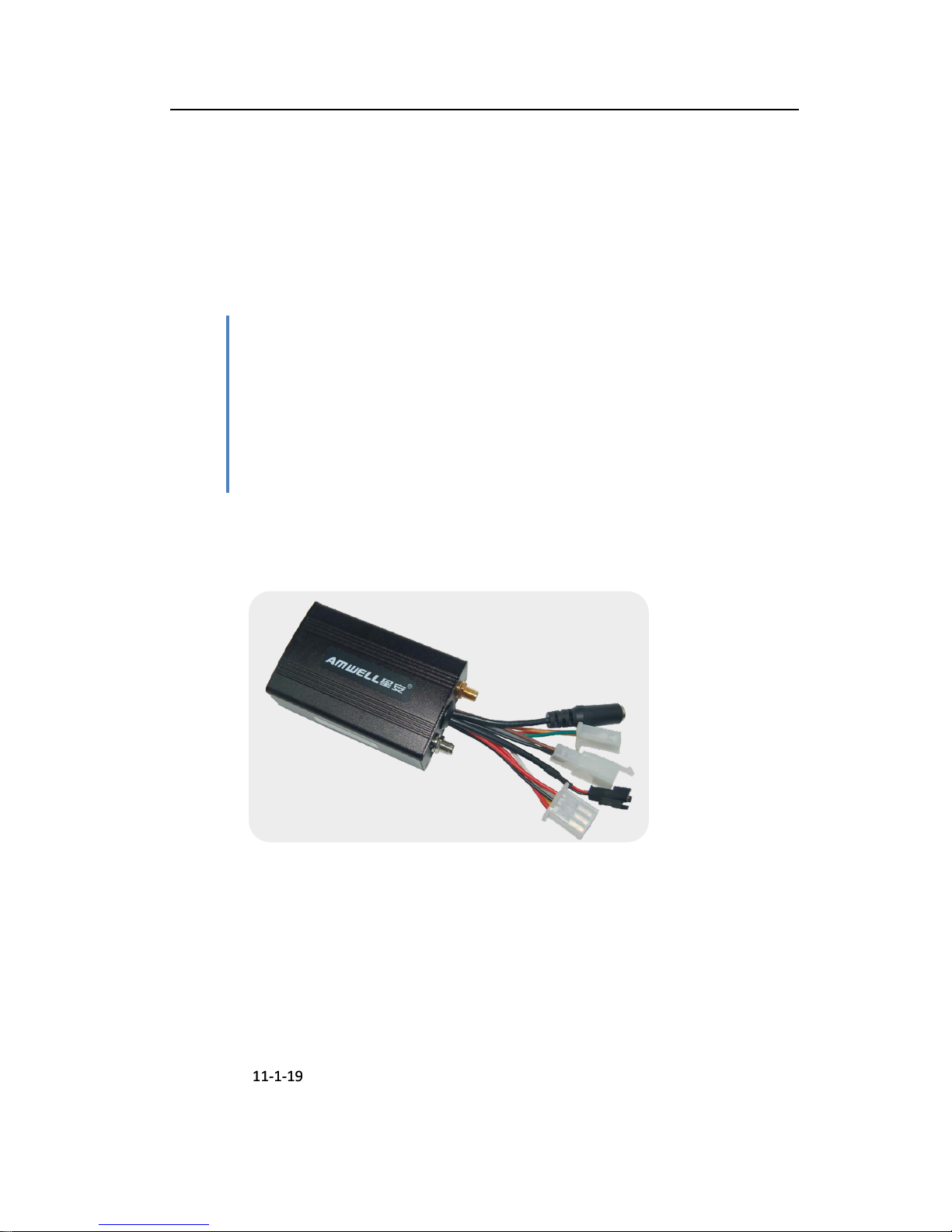
Amwell GPS Tracking Unit
2011-1-19
2011-1-19
Page 2

Shenzhen Union Security industr y C o., Ltd
T360-103 User’s Manual 2 / 22
Index
1. Product Profile ............................................................................................................................. 3
2. Technician parameter ................................................................................................................. 5
3. T360-103Packing list .................................................................................................................. 6
3.1. Standard Accessories ..................................................................................................... 6
3.2. Optional accessories ....................................................................................................... 6
3.3. Packing View and Serial setting cable .......................................................................... 7
4. T360-103 Indicator light description ........................................................................................ 8
5. Functions Description ................................................................................................................. 9
5.1. GPRS Mode Function ...................................................................................................... 9
5.1.1. Real-time positioning .......................................................................................... 9
5.1.2. Tracking a car ...................................................................................................... 9
5.1.3. Cut Fuel/Recover Fuel ........................................................................................ 9
5.1.4. Alarm functions ................................................................................................... 9
5.1.5. Remote Control functions ................................................................................ 11
5.1.6. Mileage statistics ............................................................................................... 11
5.2. SMS Mode Function (Command list in appendix 1) ................................................. 12
5.2.1. Real-time position ............................................................................................. 12
5.2.2. Tracking function ............................................................................................... 12
5.2.3. Cut Fuel/Recover Fuel ...................................................................................... 12
5.2.4. Alarm functions ................................................................................................. 12
5.2.5. Remote Control Functions ............................................................................... 12
6. Device Installation .................................................................................................................... 13
6.1. Prepare works ............................................................................................................... 13
6.2. Setting steps .................................................................................................................. 13
6.3. Install in a car................................................................................................................ 15
6.3.1. Prepare for install .............................................................................................. 15
6.3.2. Device diagram .................................................................................................. 15
6
.3.3. Main Device Installing ...................................................................................... 15
7. Extended function ..................................................................................................................... 18
8. FAQ ............................................................................................................................................. 19
Appendix1. SMS Command List .......................................................................................................... 20
Page 3

Shenzhen Union Security industr y C o., Ltd
T360-103 User’s Manual 3 / 22
1. Product Profile
Thank you for choosing our company's T360-103 GPS tracking products,
please carefully read the instructions before operating.
T360-103 satellite positioning system combined with positioning, monitor and
observe, alarm for help, advertising, vehicle scheduling, image capture and
tracking functions, it’s easy to use, easy to operate, the characteristics of a
full-featured, the main applies to vehicles and other mobile object location and
tracking services.
T360-103 fully supports the GPRS network data transmission function, GPRS
platform can be combined with software to make it more widely used in
large-scale cluster monitoring, emergency scheduling, location-based services,
traffic safety management and many other fields.
Product Features:
Support GPS positioning mode.
Support GPRS network data transmission.
Support for multi-directional terminal param eter settings.
Support for auto m atic sleep, standby operating current is only 100mA.
Support for peer-to-peer monitoring, poi nt to group con trol, group all -round
monitoring of the group.
Combined with a nti-theft, positi oning, mo nitoring contro l, ala rm, such as first
aid and tracking mult i ple functions with a full rang e of integrated products.
【Note】
Herein after referred to as the 【default user】refers to has been set and
saved to the product of all num bers communications devices.
This product is SMS / GPRS dual-communication version of the product
factory default SMS mode, GPRS mode For more information, please refer to
the instructions on the relevant SMS communication mode conversion
instructions convert.
If an error or a write command to send messages of non-default number of
instructions, this product will ignore it.
All input commands can be upper a nd lowerc ase let ters in Eng lish, b ut need
to use standard English punctuation, , must not use other input method
instead of the English punctuation. And all SMS commands is no space
character between the contents.
This product is factory default password is 【1234】, convenience-oriented
Page 4

Shenzhen Union Security industr y C o., Ltd
T360-103 User’s Manual 4 / 22
brochures to explain the following command operation for some of those
involved in your password are the product's default password 【1234】
This product is not waterproof, choose the dry location to install, a nd pay
attention to water moisture.
Please installed and use this product properly
Page 5

Shenzhen Union Security industr y C o., Ltd
T360-103 User’s Manual 5 / 22
2. Technician parameter
Name Parameter
Gift Box Dimension 180mm × 128mm × 60mm
Color Black
Working voltage 9V -- 30V DC
Working current
80 mA – 110 mA(12V/DC)
Back-up battery life time Up to 1 hour
Tracker size 85mm X 55mm X 29mm
Weight Tracker weight 0.2kg Tota l packet 0.5kg
Working temperature
-25℃ -- 65℃
Moisture
5% -- 95%(Non-water vapor condensation state)
GSM Frequency 900MHz/1800MHz or
850MHz/900MHz/1800MH z/190 0 MHz
GPS Module Latest U-BLOX locating module from Sweden or Skylab
GPS Sensitivity -159Db
GPS Frequency 1575.42 MHz
Receiving panel structu re GPS module 32-channel
Locating accuracy
< 5m (95%)
Cold start time
< 45s(in average)
Heat start time
< 2 s (in ave rage)
LED indicator light
usage of green / re d d u a l -color LED indicator light shows the
GPS / GSM status
GSM Chipset
HUAWEI or SIMCOM
Page 6

Shenzhen Union Security industr y C o., Ltd
T360-103 User’s Manual 6 / 22
3. T360-103Packing list
3.1. Standard Accessories
Accessory QTY Image Function
Packing 1PCS
Gift box packing
Main device 1PCS
T360-103 main device
GSM
Antenna
1PCS
Receiving GSM network signal
GPS Antenna 1PCS
Receiving satellite locating signal data
Relay 1PCS
Implementation of the core components
of cut off and restoration of
circuits/circuit of the relevant action
command
MIC 1PCS
User to monitor the voice inside the
vehicle, to assist users to determine
more accurate
6PINcable 1PCS
Product and vehicle or other equipments
installing cable connecting with the main
wire(SOS button i ncluded).
Binding
cables
3PCS /
For fixing the main device and wire used
Double
stickers
2PCS / For fixing the main device and wire used
3.2. Optional accessories
Name QTY Image Function
Bus Camera 1PC
Photographing in vehicles
Page 7

Shenzhen Union Security industr y C o., Ltd
T360-103 User’s Manual 7 / 22
Taxi camera 1PC
Photographing in vehicles
3.3. Packing View and Serial setting cable
Page 8

Shenzhen Union Security industr y C o., Ltd
T360-103 User’s Manual 8 / 22
4. T360-103 Indicator light description
LED light Light on Light off Description
Green 5 seconds 1 second GPS located
Green 1 second 1second GPS unlocated
Green 0.5Second 0.5Second Initialization
Red 1 second 1second Searching for GSM n et w ork
Red 0.5S 3S GSM network norm al
Red Flashing quickly transferring /receive GPRS data
Light off Device power failed or LED
indicator light error
Red Light always on In call or dialing
Page 9

Shenzhen Union Security industr y C o., Ltd
T360-103 User’s Manual 9 / 22
5. Functions Description
5.1. GPRS Mode Function
5.1.1. Real-time positioning
Monitoring center can directly locate the specified vehicle terminal call view,
in-car terminal will immediately return to the central monitoring platform details
such as vehicle location data. Location info rmation mainly include: time, longitude,
latitude, speed, location, location signs, vehicles and terminal status.
5.1.2. Tracking a car
Monitoring center can specify the device GPS data transmission time interval,
then device can upload data automatically with that interval. Factory default
upload interval is 30 seconds, adjustable range is 5-65535 seconds; if interval is
set to "" 5 seconds ", the terminal device will automatically return to the "5
seconds".
5.1.3. Cut Fuel/Recover Fuel
Monitoring center can be personalized to the designated vehicle and a remote
disconnect the circuit or to r est ore the circuit, when the vehicle termi nal receives
instruction on cut/restore fuel to take down/ restart car movements.
5.1.4. Alarm functions
Emergency alarm
When there is an emergency or ask for help, press 2 seconds on emergency
button, triggering an emergency alarm, the terminal immediately upload
emergency alarm. Control center received alarm information could confirm and
cancel alarm. (Installation please refer to the installation section【101A6B)
instructions】.
If the terminal is currently in standby sleep mode, wake-up immediately to
activate and exit standby mode, will also alarm to the Control center.
Over speed alarm
Traf fic sp eed a larm r efers t o t he device in accordance with the sp eed to allow the
user to set the value of consta ntly monitoring the vehicle speed, when the vehicle
speed exceeds pre set all owabl e va lue, the device will send over speed alarm data
reported to the Center, when the speed dropped to the default values that the
Page 10

Shenzhen Union Security industr y C o., Ltd
T360-103 User’s Manual 10 / 22
abolition of alarm. Center received alarm data may confirm or cancel the alarm.
Driving speed alarm set value in the 0-255 (km/h) range.
Geo-fence alarm
Exit into the Geo-fence alarm refers to the user to set up and one or more
permitted to enter or exit out of the region ban, issued and saved to the device,
device according to the user to set t he value of the const ant monitoring of vehic le
movement position, when the vehicl e latitude and longit ude value exc eeds a user
preset value, that is reported the corresponding data to enter or exit alarms,
when the vehicles return to the user default settings will be canceled within the
police. Users can confirm or cancel the alarm on demand. Electronic fence
delineated the largest number of 25, delineation of the size limitation.
Device main power loss alarm
When the vehicle power supply was cut off the terminal will issued a power off
warning in 3 seconds, at the same time start the backup battery power supply
(can last around 30min), again automatically detect whether the alarm is
canceled after 30 seconds, Center received alarm information could confirm and
cancel alarm. If the terminal is currently in standby sleep mode, will wake-up
immediately to activ ate and exit standby mode, will also alarm to the center.
The fatigue driving ala rm
Overtime drive; also known as fatigue, driving is mainly a continuous monitoring
of driver fatigue, driving out to bring the traffic safety problems. When the alarm
function to open overtime driving, driving conditions to determine the state of
ACC in the ON state dura tion beyond the default values, ie centr al issue, when the
ACC began to open the device time, when the preset value is exceeded, the
device will be immediately sent to the Center o f fatigue driving alert data, the user
can confirm or cancel the alarm on demand.
Illegal ignition warning
Illegal fire alarm is set on condition the driver are not allowed to start engine
within the restrict time. The device will report data o n illegal fire alarm. Determine
the conditions for this f unction is mainly "user to set the start / end da te and time,
ACC status from OFF to ON" .
Functional implementations: Users can set the open platform software illegally
firing the starting date and end date, from start / end time. When the vehicle
starts vehicle within a preset time, this device will immediately uploaded to the
center platform of illegal fire alarm information. Center received the information
after temporary abol ition of the alarm, can also cancel the alarm.
Page 11

Shenzhen Union Security industr y C o., Ltd
T360-103 User’s Manual 11 / 22
Custom Defined Alarm
The device with 2-way custom test line (the test line of the definition and
installation please refer to the section described in the insta llation of the 【101A2B
installation instructions】) in order to meet specific customer needs. When the
user needs to customize sensor alarm function can be defined according to their
own needs the name of the line alarm. As defined by the test line before it is
triggered, the device will immediately send a custom alarm to the central data
center can be confirmed after the receipt of alarm information and cancel alarm .
5.1.5. Remote Control functions
Remote monitoring
Monitoring center communication plat form can be set as monitor callback number,
send "listen in" command; the terminal will automatically call-back telephone
eavesdropping operation. (Requires SIM card enable call function)
Remote modify Control centre parameters
Device parameters can be changed by GPRS according to user needs, include
server IP/port and APN (Access Point Name). After the device is set to cha n ge to
new IP /port and APN, device will restart and parameters effective immediately.
Remote restart terminal equipment
Abnormal when an individual terminals on-line or for other reasons need to
restart the device, the user can correspond to the terminal through the platform
to restart the instruction issued.
Remote check the version and device status
In order to facilitate the timely after-sales and technical personnel to follow up
and follow-up technical upgrades, etc., the terminal device with terminal softwa re
version of the remote query feature. Users also can check the device status
remotely; include devic e par am eters, device GSM/ GPS sta tus, ACC status, and so
on.
5.1.6. Mileage statistics
The beginning of this equipment from loading automatically calculate mileage,
and mileage statistics from time to time to report to center platform, the center
can take advice on car mileage table stor ed data; also the centers can clear the
vehicle mileage data stored by platform, or be derived in accordance with set
Page 12

Shenzhen Union Security industr y C o., Ltd
T360-103 User’s Manual 12 / 22
time-related mileage sta ti sti cs. The mileage statistics value no bigger than 16000
km.
5.2. SMS Mode Function (Command list in append ix 1)
5.2.1. Real-time position
Device user can use authorized cell phone number send TRACK ONCE command
content to device, and device will reply real-time attitude and longitude to user’s
cell phone immediately.
【Note】: SMS have much longer dela y time tha n GPRS, and ma y have d iff erent
delay time in different mobile networks. Please find d etail command in appendix 1
5.2.2. Tracking function
User can set a time interval to device for data uploading, after that, device will
send position data to the primary authorized number.
【Note】: The SMS tracking t ime interv al unit is minut e, the minimum int erv al is
1 minute. Device will send longitude and latitude to home number (primary
authorized number) with set interval. Please find detail command in appendix 1
5.2.3. Cut Fuel/Recover Fuel
Users can send cut/recover Fuel text command to device to stop/recover a car.
Please find detail command in appendi x 1
5.2.4. Alarm functions
SOS Alarm
Over Speed Alarm
Device Main Power Loss Alarm
Customer Defined Alarm
5.2.5. Remote Control Functions
Remote Monitoring
Remote Modify Communicate Parameters
Remote Restart Device
Remote Check Device Status
Page 13

Shenzhen Union Security industr y C o., Ltd
T360-103 User’s Manual 13 / 22
6. Device Installation
After you get T360-103 product, please familiar with it and test it before you
install it in a Car, please check the packing list and make sure the packing and
product quality well.
6.1. Prepare works
Amwell GPS product
Serial setting cable and TEsetting software
Local GPRS SIM card
12V DC power supplier
Computer with COM port (if do not have COM port, can use USB to serial
cable instead)
6.2. Setting steps
Step1
. Insert SIM card into the Amwell GP S device.
Step2
. Connect the antennas (GSM antenna and GP S antenna) to device
Step3
. Connect the power cable to 12V DC power supplier (according to the
diagram of device connection in part 6.3.3.2)
Step4
.Connect the device with your computer via serial setting cable (or via
serial cable and USB to serial cab le)
Step5.
Start program TEsetting
Step5.1
. Select communicate type and set communicate port.
1.Select communicate type
:269
by LCD, 103 by control Handle
2.Communicate port, select port in use
3. Click
to open
the port
Page 14

Shenzhen Union Security industr y C o., Ltd
T360-103 User’s Manual 14 / 22
Step5.2
.Check communicate
Step5.3.
Set center par ameter and APN
3. Click
to check if the
serial communicate is ok
Page 15

Shenzhen Union Security industr y C o., Ltd
T360-103 User’s Manual 15 / 22
6.3. Install in a car
6.3.1. Prepare for install
This device using in 12V, 24V motor vehicles, wi ll not conflict with the original car
system, in order to facilita te fault diagno sis and unusual dispute aft er installation,
please check the pre-installation inspection and truthfully inform the owner.
Check all function whether it is normal for the vehicle. Such as: lights, small
lights, turn lights, fog lights, ACC, CD drive, electric windows, remote control
cars in the original control, engine start, engine run and so on.
Check various decorative items inside the vehicle whether standards to
connect, and check if decoration of the car has damaged.
Check with the product, if is damaged, if there is exposed copper
phenomenon.
6.3.2. Device diagram
6.3.3. Main Device Installing
6.3.3.1. SIM card installing instruction
Please set up SIM card service password before installing it into the device.
T360-103 implementation of the various functions required to support the SIM card
SMS message, GPRS functionality (Internet CMNET business), make sure that the SIM
card with the functions (if required monitoring, call features, SIM card is also required
to support voi ce calls f unction ).
Installation or removal of SIM card, please do that under power off the device
Page 16

Shenzhen Union Security industr y C o., Ltd
T360-103 User’s Manual 16 / 22
completely, otherwise it is possible the SIM car burnt.
SIM card installation or removal required for "+" screwdriver inserted back-end of
equipment, forced inside the top hole until the SIM card connectors automatically exit
the host. Specific installation steps please refer to the following diagrams:
6.3.3.2. 103A6A Cable Installation Diagram
Power positive wire (red):
power positive installation in general with the battery positive, or with the fuse box’s total
power input regular wire (+12 V). During
installation process must choose thick (+12
V) wires. And bind up the joint.
Power negative electrode (black):
The vehicle body metal itself is a negative
electrode; usually the installers will choose a
screw and loosen it, and then tied to
negative electrode wire, tightening it.
However, it will be oxidized after longtime, so
it will cause bad effect to the device.
Most of the vehicles need one or more screws to the anti-oxidation process, adopt ed with
multi-point grounding after gather up all cathode-ray by parallel w ay, to ensure the grounding.
So we should adopt the second way for
grounding. (Remarks: Its t heory is the same as
(+12) electricity cable, better to be thick.
ACC detecting wire (white):
This wire is majorly for detecting the ACC si gnal.
Please refer to the illustration f or the ACC signal
Page 17

Shenzhen Union Security industr y C o., Ltd
T360-103 User’s Manual 17 / 22
in the vehicle key insert part.
Electricity Power cut wire control (yellow):
T360-103 of the power control wire (yellow)
is mainly used to meet with the power relay
circuit to cut off the motor fuel or engine
circuit, forced to stop the engine running.
Emergency button:
Basically use for the driver while face an emergency situation, can
trigger the button T360-103 equipment to issued a distress call to
the center information platform. Usually trigger button does not
easily found location.
6.3.3.3. 103A4A Installation Instructions (optional)
Lines are installed 103A4A main camera cable connector; detaile d installation and use please
refer to the "camera ins tallation inst ructions" and "pl atf orm ope rating i nstru ctions" relate d to
the contents of the operation.
This Port also use for serial setting and firmware updating. For serial setting please see part
6.2; and for firmware updating please contact us.
6.3.3.4. GPS/GSM Antenna installing Guide
The location of device is recommended to install in the following locations and require
ensuring the right way, at the same time, please pay attention to the concealment.
In front bumper or near the headlight.
Between the rear case of the engine and windshield glass.
Before the bottom of the windshield and dashboard, GPS antenna should face to the sky.
(Note: Dashboard with many metal supporting places, so please put it in the upper place,
and avoid vehicle cables a nd speak or air condition where with st rong magnet ic,distance
with 20CM
The back seat of the cab below the rear windshield.
【Note】
During the installation process, please ensure GPS antenna head to being on a horizontal
plane , and without metal material covered.
Page 18

Shenzhen Union Security industr y C o., Ltd
T360-103 User’s Manual 18 / 22
6.3.3.5. Monitor Microphone (J1)
Please pay attention to the monitor MIC, make sure it is far
away from magnetic fields, such as: sound box speakers,
power cord, usually installed on the cab roof near the top.
【Note】: This function must support SIM card with voice
function
6.3.3.6. Louder Speaker (J2)
This is a optional part of 103, if you want the two way
communication function, you need select louder speaker
accessory and connect to this port.
7. Extended function
Photo taking function:
The cam era is infrared camera. It will automatically start the infrared function while in
the dark enviorenment.
The camera also works even using the backup battery while the main power is off.
The resolution of the photo is: 240x320 or 480x640. The size is from 10K-20K.
We could send ph oto-taki ng co mmand throu gh the m onitorin g softw are i n GPRS mode .
Also it sup port be triggered by the SO S button or by other triggers.(like door trigger or
other self-defined trigger). You can enable or disable the trigger function. Defaulted:
closed. For more details, please go to check the camera's user manual.
Note: Camera is optional devices.
Page 19

Shenzhen Union Security industr y C o., Ltd
T360-103 User’s Manual 19 / 22
8. FAQ
NO Problem Reason Solution
1
Light off af t er
device connected
with power
Power installed
incorrectly
1. power of positive and negative reversed
installed
2. the power of the cathode not connected;
3. the original car is controlled by main power
switch (mostly in 24V vehicle.)
Power disconnection
1. The electricity installing cable is power off
2. fu se disconnect
3. Main device and the connector to installing
lines bad connected
Indicator light fail Bad quality for the indicator light
2
Power indicator
light flashing
quickly or long
time light on.
SIM card could not be
detected after
electricity power on,
and the device reset
repeatedly.
1. Did not put in SIM card
2. SIM card inserted into the wrong direction
3. SIM card failure.
3
Equipment are
often not
positioned
GPS antenna fail
1. The installation of GPS antenna location is
incorrect,
2. GPS antenna quality problem, please change
another one.
3. GPS antenna and main device connecting
point is loosen or wrong place
4. GPS ante nna hea d at tac ked by w ate r or dam p
Signal interference
The electromagnetic interference Speaker
the market part of the electronic dog, wireless
MP3 signal interference
explosion-proof film covered to stopp e d GPS
signal
4
Sending SMS to
SIM card inside
the device, but no
response
Don’t reply messa ge s
Command format error
punctuation errors
no money in SIM card balance
Occasionally don’t
reply messages
Bad signal
Installation position wrong signal shielding
serious
5
There is noises
when listen in
Installation problems
Please avoid magnetic field installing power
supply
6
No alarm when
device power off
Back-up battery failed
to open
Find a local dealer to open backup battery switch
7
Unable to power
on the vehicle
Installation or
operation function
improperly adjust
1- Due to operation mistake to cut the fuel
pump.
2- relay failed or the installation wires
damaged and short-cut body.
Page 20

Shenzhen Union Security industry Co., Ltd
T360-103 User’s Manual
20 / 22
Appendix1. SMS Command List
NO IUSSE SEND COMMAND ANSWER COMMAND REMARK
1
SET SERVER IP
AND PORT
AS1234IPPO:119.147.23.108;7
777;#
IPPO:119.147.23.108;7777,26339788;OK Response content is “IP””Port””Current Device ID”
2 SET TERMINAL ID AS1234IDDO:26339788# IDDO:26339788;OK Response Current Device “ID”
3
A
P
N
Access Point
Name
AS1234APN:CMNET# APN:CMNET;OK At most 39 Character
4 APN user name AS1234USER:USER# USER:USER;OK At most 39 Character
5 APN password AS1234GPRSPASS:GPRS# GPRSPASS:GPRS;OK At most 39 Character
6 Restart Device AS1234RSGS# GSM/restart; OK Device Restart
7 Factory Reset ASAX*%UPAS# PASSWORD:1234;OK
All the parameters will be reset to f actory set exc ept
IP、Port、Device ID and APN
8
Device Status
Enquiry
AS1234STATE#
ID:99999999 VER:V1.05
IP:119.147.23.108,7777 CEN: AUT:
CSQ:19 GPS:OK ACC:ON GPRS:30
POWER:ON NETTYPE:SMS
1、 ID:Current Device ID
2、 Ver.:Current firmware version
3、 IP:Current IP and Port
4、 CSQ:Current GSM signal strength
5、 GPS:GPS available or not
6、 ACC:Current ACC status
7、 GPRS:Current GPRS data upload interval
8、 POWER:Current Power mode
9、 NETTYPE:Current Communicate mode
9 Awake up Device AS1234SLEEP:# SLEEP:OFF T emp leave sl eep mode, will sleep again after 25 min
10 Open/Close
AS1234WAKEUP:5#
WAKEUP:5
1、 Unit:“hour”;
Page 21

Shenzhen Union Security industry Co., Ltd
T360-103 User’s Manual 21 / 22
Standby Mode
2、 T ype and range:“0” Close;1~18:sleep for this
time and wakeup for 25minutes.
Standard function
1
Communicate Mode
Set
AS1234SMGP:0#
AS1234SMGP:1#
AS1234SMGP:2#
SMGP:UDP;OK
SMGP:TCP;OK
SMGP:SMS;OK
1、“0”UDP Mode;
2、“1”TCP Mode;
3.、“2”SMS Mode
2
Home Number Set
AS1234HOME:13510642316#
AS1234HOME:0#
HOME:13510642316;OK
HOME:CLEAR;OK
3
Authorized
Number2 Set
AS1234EMPOWER:135902518
97#
AS1234EMPOWER:0#
EMPOWER:13590251897;OK
EMPOWER: CLEAR;OK
4
Change Device
Password
AS1234PASSWORD:5678# PASSWORD:5678;OK
5
Track Once AS1234WHERE#
TRACK :speed:0;
http://maps.google.com/maps?hl=en&q=
+22.59325,+113.87099
Send once
6
SET TRACK Interval
(send to Control
Center only)
AS1234TRACK:3#
AS1234TRACK:0#
1、【 TRACK:3;OK】
2、【 TRACK:ERR】
3、【 TRACK:OFF;OK】
4、TRACK :speed:0;
http://maps.google.com/maps?hl=en&q=
+22.59325,+113.87099
1、Unit:“Minutes”
2、type:“0” cancel ;
7
Cut Fuel AS1234ENGINE:OFF# ENGINE:OFF;OK
8
Recover Fuel AS1234ENGINE:ON# ENGINE:ON;OK
9
Monitoring Number AS1234LISTEN:13481944860# Device will phone to telephone nuber13481944860
Page 22

Shenzhen Union Security industry Co., Ltd
T360-103 User’s Manual 22 / 22
10
SET Speed Limit AS1234SPEED:120#
AS1234SPEED:0#
ESPE:120;OK
ESPE:OFF;OK
1、Unit:“km/h”
2、Type and range:“0”cancel spee d limit
11
User Defined Alarm 1 AS1234 DEFINED1:1#
AS1234 DEFINED1:0#
User-defined1:ON;OK
User-defined 1:OFF;OK
Value type:“0”forbid;“1”open
(The alarm information will only send to authorized
Number and center numb er when Device work in
SMS mode )
12
User Defined Alarm 2 AS1234 DEFINED2:1#
AS1234 DEFINED2:0#
User-defined2:ON;OK
User-defined 2:OFF;OK
Value type:“0”forbid;“1”open
(The alarm information will only send to authorized
Number and center numb er when Device work in
SMS mode )
13
SOS Alarm SOS Button Pressed
SOS:Latitude:+22.61916;Longtitude:+1
13.85543;speed:52;ACC:ON
for 3s, device will send sos alarm once to home
number and authorized number set.
2.Detail alarm content see【Note 2】
14
Main
Power loss
Alarm
Main power supply cut (backup
battery must open)
POWER:
Latitude:+22.60227;Longtitude:+113.86
878;speed:44;ACC:OFF
1. Device end sos alarm once to home number and
authorized number set.
2. Detail alarm content see【Note 2】
Note:In all the SMS commands , the delete method of all the settable p arameters is to c hange the par ameters to ‘0’,it will be recognized as inv alid command
if leave it blank。
Note 1:
SMS Command format:
AS 1234 APN : CMNET
#
Start chars Password Type Content End Char
Note 2
TRACK: Latitude:+22.59429; Longitude:+113.86971; speed:0; ACC:ON
Type Current latitude Current longitude Current speed Current ACC status
 Loading...