

BIGTIDE SERVICE DOCUMENT
DVI Splitter Amplifier
DS01
User’s Manual
Preliminary version
Copyright © 2012 SHENZHEN BIGTIDE TECHNOLOGY CO., LTD

BIGTIDE DS01 V3.0
User’s Manual
Contents
1. INTRODUCTION ................................................................................2
2. SAFETY PRECAUTIONS...................................................................2
3. TECHNICAL INFORMATION..........................................................4
3.1 POWER SUPPLY .....................................................................................................4
3.1.1 AC power input ..............................................................................................................4
3.1.2 AC power loop through output .....................................................................................4
3.2 SIGNAL INTERFACE...............................................................................................4
3.2.1 Signal specifications .......................................................................................................5
3.2.2 DVI output +5V Pin 14 load capability........................................................................5
3.2.3 Power/Sync LED indicator............................................................................................ 5
3.3 PRODUCT FEATURES............................................................................................. 6
3.4 ENVIRONMENT CONDITIONS AND RELIABILITY................................................... 7
3.4.1 Operation ........................................................................................................................ 7
3.4.2 Transport and storage (packed) .................................................................................... 8
3.4.3 Mechanical requirements .............................................................................................. 8
3.4.4 Drop Test (packed) .........................................................................................................8
3.4.5 Safety specifications .......................................................................................................9
3.4.6 Electromagnetic compatibility ......................................................................................9
3.4.7 MTBF .............................................................................................................................. 9
3.4.8 ROHS ..............................................................................................................................9
3.5 MECHANICAL SPECIFICATIONS..............................................................10
3.5.1 Outline dimensions & weight ......................................................................................10
3.5.2 Package dimension and weight ...................................................................................11
3.5.3 Mounting brackets and screws.................................................................................... 11
4. CONNECTIONS AND START-UP ...................................................13
4.1 CONNECTING THE POWER CORD AND ITS BRACKET..........................................15
4.2 START-UP MODE AND CONNECTING DVI CABLE ................................................ 15
4.2.1 Start-up with the DDC of the unit itself .....................................................................15
4.2.2 Start-up with the DDC of the desired display device ................................................15
5. FAULT DIAGNOSTICS.....................................................................16
6. REMARKS AND CONTACT ADDRESS ........................................16
- 1 -

BIGTIDE DS01 V3.0
User’s Manual
1. Introduction
This manual describes the safety precautions, specification, operation, installation of
the Bigtide DS01 DVI Splitter.
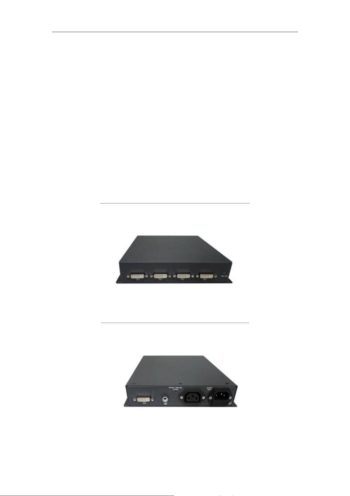
The BigtideDS01 is a DVI Splitter with one input and four outputs.
The DS01 distributes a single DVI-D input to four DVI-D outputs.
The DS01 has DDC functions by itself.
The DS01 is able to switch DDC automatically according to the preset priority.
The DS01 drives each DVI-D up to 15m at a resolution of 1600×1200@60Hz or
1920×1200@60Hz (24AWG STP).
The DS01 is able to pass the eye diagram testing.
The DS01 is powered by 100~240VAC power supply.
The DS01 can be mounted in a rack, in a drawer, on a wall, under a desk, or set on a tabletop. It
can also be used side by side.
The unit is engineered to meet all rigorous safety requirements, including UL, CUL, CE,
CCC, and to meet all rigorous EMC requirements.
The unit can fulfill QR Med6 requirements and RoHS Compliance.
2. Safety precautions
Caution
Read instructions
Read and understand all safety and operating instructions before using the device.
Follow warnings
Follow all warning and instruct ions marked on the device or in the user information.
Regular maintenance are recommended
Correct and safe operation of the DVI splitter is dependent on proper transport, storage,
installation and assembly, as well as careful operation and maintenance.
For the sake of safety, the following precautions must be observed:
- 2 -

BIGTIDE DS01 V3.0
User’s Manual
Danger
There is a danger to life if the warning information is not observed. Severe
personal injury or damage to property may occur.
1. Do not open the unit yourself, because certain components inside the units are at
high- voltage.
2. Only use a perfect power supply cable, because a damaged power supply cable
may result in a fire or electric shock.
3. Only use the same type of fuse 3.15A/250V
4. Do not insert any objects into the housing, because objects inserted into the
housing may result in damage to the unit.
5. Do not expose the unit to rain or excessive moisture.
6. Do not hurt yourself when moving the unit.
Warning
Incorrect installation may result in extensive damage to property. Installation should be
carried out by trained personnel.
1. When installing your electrical system with our products, please observe the safety
requirements of EN60601-1-1 (IEC601-1-1).
2. Take appropriate measures to particularly ensure that discharge currents remain below
the required limits.
Appropriate measures:
• Disconnecting devices for signal input and output unit.
• Use of a safety transformer.
• Use of additional PE conductor.
3. Only use the signal cables and interface cables specified by the manufacturers for the
installation
4. Use power cords with a PE contact.
Only insert into sockets with a PE contact.
5. Provide sufficient heat dissipation
Slots are provided at the sides of the housing.
These slots are provided to prevent overheating of sensitive components inside.
These slots must never be blocked by other objects.
6. The permissible ambient temperature range (0ºC to 45ºC) must not be violated.
7. Take care when transporting! Use the original packaging!
8. The device could be sent back to the manufacturer for recycling or proper disposal
after their useful lives. Alternatively the device shall be disposed in accordance with
national laws after their useful lives.
- 3 -
BIGTIDE DS01 V3.0
User’s Manual
3. Technical information
3.1 Power supply
3.1.1 AC power input
Input Voltage
: AC100-240 V± 10%
Current (max) : 0.35A (without AC power loop through output)
: 2A (with AC power loop through output)
Frequency
: 50/60Hz ± 3Hz
Power Consumption : <20W (without AC power loop through output)
3.1.2 AC power loop through output
Output Voltage
Current (max) : 1.65A
Frequency
: AC100-240 V± 10% (Equal to input)
: 50/60Hz ± 3Hz (Equal to input)
3.2 Signal interface
OUTPUT4
DVI-D
OUTPUT3
DVI-D
POWER/SYNC LED INDICATOR
FRONT PANEL
Figure 1
- 4 -
OUTPUT2
DVI-D
OUTPUT1
DVI-D
BIGTIDE DS01 V3.0
User’s Manual
INP U T
DV I-D
GND
AC PO W E R O U TPU T
OUTLET 3P IEC TYPE
AC PO W E R INPU T
INLET 3P IEC TYPE
REAR PANEL
Figure 2
3.2.1 Signal specifications
Item SPEC
Digital Signal
Input
DVI-D Input
DVI-Digital
DDC via DVI
Digital Signal
Output
DVI-D Output
DVI-Digital
DDC via DVI
3.2.2 DVI output +5V Pin 14 load capability
+5V load capability: Max. current 600mA for each output DVI port.
3.2.3 Power/Sync LED indicator
Power input on without DVI digital sync input LED light and color orange
Power input on with DVI digital sync input LED light and color green
Power input off LED extinguished
- 5 -

BIGTIDE DS01 V3.0
User’s Manual
3.3 Product features
Specification
Item
Digital Input
Horizontal frequency 30kHz -82kHz
Vertical frequency 50.0Hz - 85.0 Hz (Non-Interlaced)
Video Signal Digital Video
Input Signals
Output
Signals
Sync. Signal TMDS
Pixel Clock 25.0MHz-165.0MHz
Maximum data rate 1.65Gbps
Input connector DVI-D Connector
Horizontal frequency 30kHz -82kHz
Vertical frequency 50.0Hz - 85.0 Hz (Non-Interlaced)
Video Signal Digital Video
Sync. Signal TMDS
Pixel Clock 25.0MHz-165.0MHz
Maximum Data Rate 1.65Gbps
Output connectors DVI-D Connectors
DVI-D: Over 15m at 1600×1200@60Hz
Transmission distance
(24AWG STP)
Preset Digital Timings of The Unit 36
Highest
DDC
Switching
automatically
Priority
OUTPUT1→OUTPUT2→OUTPUT3→
OUTPUT4→The UNIT
Lowest
Safety CCC, CE, CB Regulations
EMC CISPR 22 Class B, FCC part 15 Class B
- 6 -

BIGTIDE DS01 V3.0
User’s Manual
Plug and Play VESA DDC2B
Environment
Condition
Power
Supply
Operating temperature
Operating humidity
0~45 degree C
20%~85% (without condensation)
AC 100-240V 50/60HZ ≤ 0.35A (without
AC power loop through output)
Input Voltage
AC 100-240V 50/60HZ ≤2A (with AC
power loop through output)
Power Consumption
<20W (without AC power loop through
output)
Input Connector IEC320 C14
Output Voltage
AC100-240V, 50 / 60Hz; ≤1.65A
Output Connector IEC320 C13
DVI-D Signal Cable 2.0 m
Accessories
AC Power cord (Extension
Type)
Green-yellow PE cable 3.0 m; 4 mm2
Mounting brackets and
Screws
3.0 m
All kinds for assembling the unit.
User’s manual English and Chinese (CD)
3.4 Environment conditions and reliability
3.4.1 Operation
Ambient temperature range
Temperature gradient
Humidity
Atmospheric pressure 1060 – 700 hPa (0 -- 3048m)
0 -- +45℃
Max. 6℃/h, no condensation
20%~85%
- 7 -

BIGTIDE DS01 V3.0
User’s Manual
3.4.2 Transport and storage (packed)
Ambient temperature range
Temperature gradient
Humidity
-20 -- +60℃
Max. 10℃/h, no condensation
10%~95%
3.4.3 Mechanical requirements
Packed unit
Shock Class 2M2 according to IEC721
Vibration Class 2 according to IEC68-2
3.4.4 Drop Test (packed)
According to IEC68-2
Corner
Edge
Surfaces
(Cushion should be changed to new one.)
Corner
Edge
Position Height
1 100cm
3,2,4 100cm
A,B,C,D 100cm
E 100cm
F 100cm
5 100cm
6,7 100cm
- 8 -

BIGTIDE DS01 V3.0
User’s Manual
Figure 3
3.4.5 Safety specifications
Safety standards
Approvals CCC, CB
Conformity CE
EN60601
3.4.6 Electromagnetic compatibility
IEC60601-1-2
EMC
CISPR22 /24 CLASS B
FCC Part 15 CLASS B
3.4.7 MTBF
100000 hours
3.4.8 ROHS
ROHS Compliance
- 9 -

BIGTIDE DS01 V3.0
User’s Manual
3.5 MECHANICAL SPECIFICATIONS
3.5.1 Outline dimensions & weight
Figure 4
Item Set
Width 220.00mm
Size of set
Housing components Aluminum
Ventilation slots In two sides.
Connection panel At rear and front
Net weight Approximately 2.4 Kg
- 10 -
Depth 179.80mm
Height 44.00mm

BIGTIDE DS01 V3.0
User’s Manual
3.5.2 Package dimension and weight
D
H
W
Figure 5
Width (mm)
Outer size of box
Depth (mm)
Height (mm)
Gross weight Approximately 5.0 Kg
3.5.3 Mounting brackets and screws
Figure 6 Figure 7
Power card bracket Bottom mounting bracket
450mm
350mm
100mm
- 11 -

BIGTIDE DS01 V3.0
User’s Manual
Figure 8 Figure 9
Side mounting bracket Side overlap mounting bracket
Figure 10 Figure 11
Rubber foot Connecting bracket
Figure 12 Figure 13
Machine screw M4×6 and M3×6 Machine screw cut-M4×8
Figure 14 Figure 15
Self tapping screw M4×10 Nut M4
- 12 -

BIGTIDE DS01 V3.0
User’s Manual
4. Connections and start-up
Caution
In order to ensure safety operation of the equipment, close attention must be paid to the
information contained in this User’s Manual as well as the warnings in section2 “safety
precaution”.
DDC switching
1. The unit has DDC functions by itself.
DDC switching priority:
2.
Highest Output1→Output2→Output3→Output4→Device itself Lowest
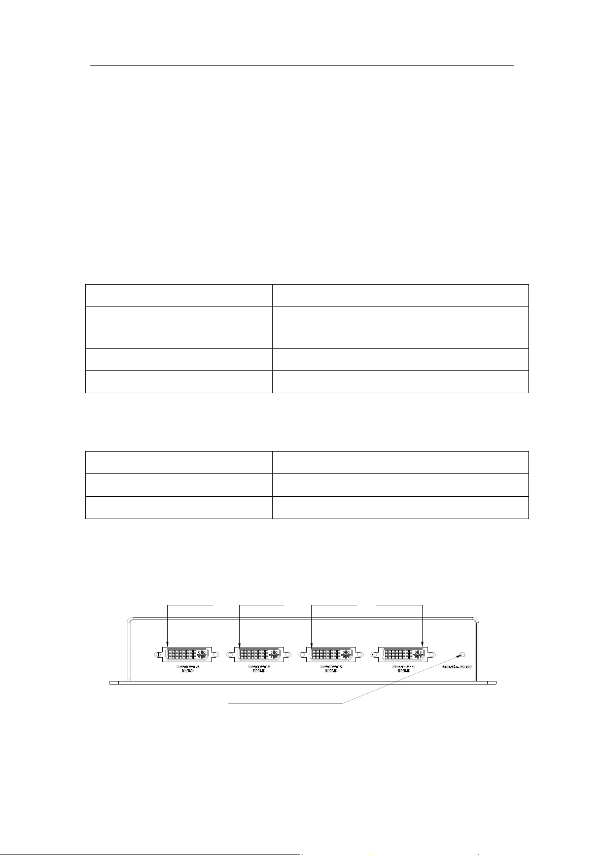
Front panel
OUTPUT4
DVI-D
Output DVI-D female connector
The output DVI-D signal with a resolution of 1600
be driven up to 15m over DVI cable made of 24 AWG STP cable.
Power/sync LED indicator
Power input on without DVI digital sync input: LED light and color orange
Power input on with DVI digital sync input: LED light and color green
Power input off: LED extinguished
Note
1.
The transmission distance varies greatly depending on the signal resolution, the type of
DVI Cable, graphic card, and display used in the system.
2. Although DVI dual link connectors are used, the device is only compatible with
single-link DVI-D video signals.
OUTPUT3
DVI-D
POWER/SYNC LED INDICATOR
OUTPUT2
DVI-D
FRONT PANEL
Figure 16
×1200@60Hz or 1920×1200@60Hz can
OUTPUT1
DVI-D
- 13 -

BIGTIDE DS01 V3.0
User’s Manual
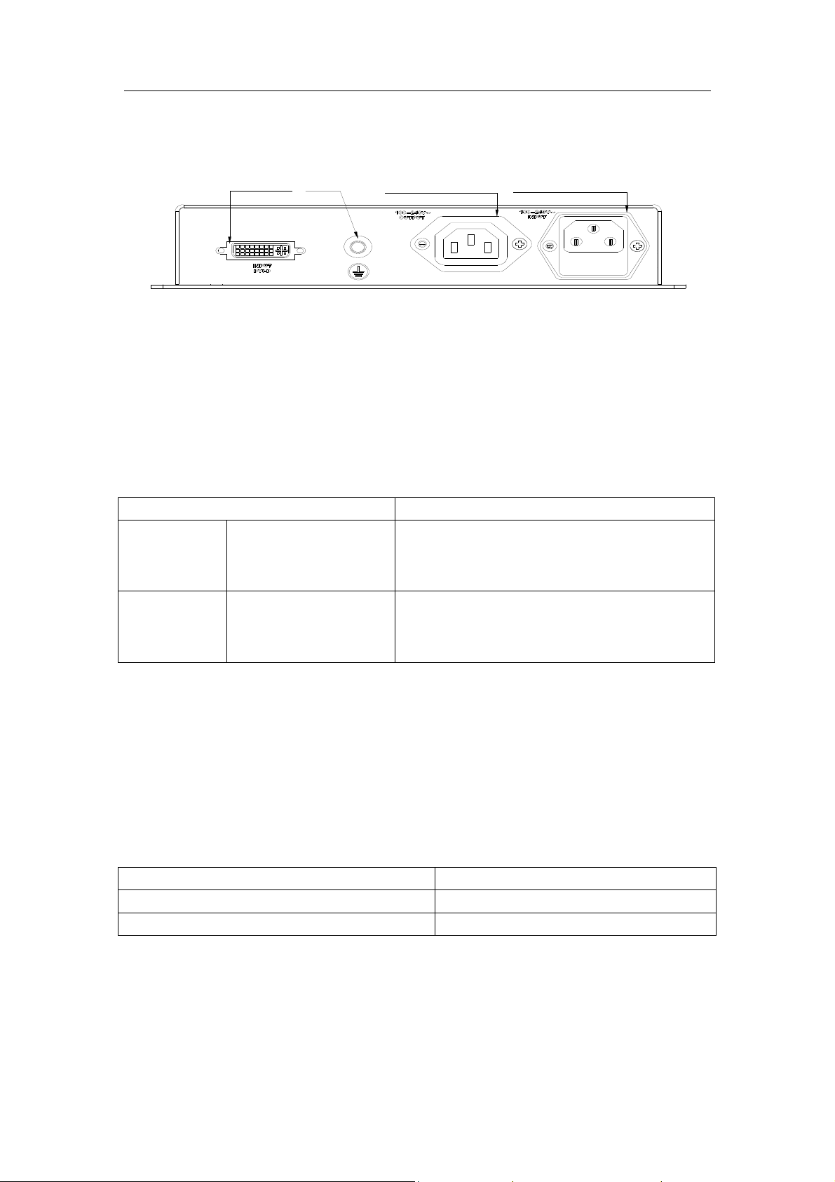
Rear panel
INP U T
DV I-D
GND
AC PO W E R O U TPU T
OUTLET 3P IEC TYPE
AC PO W E R INPU T
INLET 3P IEC TYPE
REAR PANEL
Figure 17
DVI-D signal input
Equalizes the DVI input, ensuring signal integrity.
AC power input and AC power output
AC 100-240V 50/60Hz
GND
Protective earth
Note
1. Protective earth must be connected w ith PE cab le for safety.
2. When AC power output is used, the output current should not exceed its maximum value.
Connection sketch
Figure 18
Figure 19
- 14 -

BIGTIDE DS01 V3.0
User’s Manual
In order to start the unit, the following steps should be carried out in the given sequence.
4.1 Connecting the power cord and its bracket
Caution
Use a power cord with PE conductor corresponding to the safety requirement of
the respective country of use.
Remove the machine screw over PE sign, and then fix the PE cable on the housing of the unit
1.
with the machine screw.
Put the power cords on the power cord bracket.
2.
Connect the power cords into AC power input receptacle and AC power output receptacle.
3.
Connect AC power output according to the needs of the system.
Install the power cord bracket to the unit with three M3*6 machine screws and tighten.
4.
Connect the power supply socket.
5.
4.2 Start-up mode and connecting DVI cable
4.2.1 Start-up with the DDC of the unit itself
1. Connect DVI-D input connector on the unit to DVI-D output connector on the video source
device with the attached DVI-D signal cable.
2. Power on the unit.
3. Power on the video source device.
4. After start-up is over, connecting DVI output connectors on the unit to the desired display
devices with DVI-D signal cables.
5. Power on the desired display devices.
Note
DDC communication is between the video source device and the unit itself.
4.2.2 Start-up with the DDC of the desired display device
1. Connect DVI-D input connector on the unit to DVI-D output connector on the video source
device with the attached DVI-D signal cable.
2. Connect DVI output connectors on the unit to the desired display devices with DVI-D signal
cables.
- 15 -

BIGTIDE DS01 V3.0
User’s Manual
3. Power on the unit and the desired display devices.
4. Power on the video source device.
Note
DDC communication is between the video source device and the desired display device
connected to the DVI output connector of the highest DDC priority.
5. Fault diagnostics
Fault Cause Remedy
Broken fuse Inform servicing department. operation LED off
No picture appears on
the display device,
operation LED green
Power cord not inserted
or incorrectly inserted
No video signal into the
display device
Insert power cord.
Check DVI-D cable and its connection.
Abnormal picture
appears on the display
device, operation LED
green
operation LED orange No video signal into the
Abnormal video signal
into the display device.
unit
Check DVI-D cable and its connection.
Check video source and DVI-D cable
connection.
6. Remarks and contact address
Invalidity of guarantee
All unauthorized electrical or mechanical alterations on or in the unit result in loss of the
guarantee.
Information on the User’s Manual
For clarity reasons, this User’s Manual does not contain all detailed information on this product.
Your attention is additionally drawn to the fact that the contents of this User’s Manual are not part
of a previous or existing agreement, commitment or statutory right and do not change the latter.
Guarantee
All commitments on the part of BIGTIDE are contained in the respective sales contract which also
contains the complete and solely applicable warranty conditions. These warranty conditions in the
contract are neither extended nor limited by the contents of User’s Manual.
- 16 -

BIGTIDE DS01 V3.0
User’s Manual
Repairs
Please contact your distributor from whom you originally purchased the product.
Environmental protection
When disposing of the device, the requirements and laws in the respective country must be
observed.
Contact address
Name of Manufacture: Shenyang Torch-Bigtide Digital Technology Co., Ltd.
Address: No.18-8B, Yaoyang Road, Huishan Economic Development Area, Shenbei New District,
Shenyang, China 110164
Person to be contacted: Mr. Chen Baohu
Tel: 86-24-88087621
- 17 -

FCC
6WDWHPHQW
Federal Communication Commission Interference Statement
This equipment has been tested and found to comply with the limits for a Class B digital device,
pursuant to
Part 15
against harmful interference in a residential
radiate radio
of the FCC Rules. These limits are designed to provide reasonable protection
frequency energy
installation.
and, if not installed and used in accordance with the instructions,
This equipment generates, uses and can
may cause harmful interference to radio communications. However, there is no guarantee that
interference will not occur in a particular installation.
If this equipment does cause harmful
interference to radio or television reception, which can be determined by turning the equipment off
and on, the user is encouraged to try to correct the interference by one of the following measures:
-Reorient or relocate the receiving antenna.
-Increase the separation between the equipment and receiver.
-Connect the equipment into an outlet on a circuit different from that to which the receiver is
connected.
-Consult the dealer or an experienced radio/TV technician for help.
This device complies with Part 15 of the FCC Rules. Operation is subject to the following two
conditions: (1) This device may not cause harmful interference, and (2) this device must accept any
interference received, including interference that may cause undesired operation.
FCC Caution: Any changes or modifications not expressly approved by the party responsible for
compliance could void the user's authority to operate this equipment.
 Loading...