

Customer Specification
HL1916
19 Inch LCD Display
Name Department/Title Date Signature
Cheng HuanJun
Xu Bin
SSME CT PL
Bigtide R&D VP
Last change: 27
th
, Oct. 2005
Copyright @ SSME (SIEMENS
Medical Equipment Ltd.) All
rights reserved
HL1916
Page 1 of 32

CONTENTS
1. SCOPE.....................................................................................................4
2. ELECTRICAL PERFORMANCE ....................................................... 5
2.1 Power Supply...................................................................................................5
2.2 Power Management........................................................................................5
2.3 Signal Interface ...............................................................................................5
2.3.1 Signal Specifications.................................................................................6
2.3.2 D-SUB Connector and Pin Assignment (Figure1)....................................6
2.3.3 Digital Visual Interface and Pin Assignment (DVI)..................................7
2.3.4 Control Interface.......................................................................................7
2.4 Product Features..............................................................................................9
2.5 Screen Performance......................................................................................10
2.5.1 Standard Testing Conditions...................................................................10
2.5.2 Brightness...............................................................................................11
2.5.3 V iew angle..............................................................................................11
2.5.4 Brightness Uniformity ............................................................................11
2.5.5 Contrast radio..........................................................................................11
2.5.6 White Color Coordinates ........................................................................11
2.5.7 Response T ime........................................................................................11
2.5.8 Color Gray ..............................................................................................11
2.5.9 Gamma Curve.........................................................................................12
3. OPERATING GUIDE..........................................................................14
3.1 Keys assignment ...........................................................................................14
3.2 Key Functions without active OSD Menu...............................................15
3.3 Key Functions in the OSD Menu ..............................................................15
3.4 Submenu Calls...............................................................................................15
3.5 Locking of OSD Menu ................................................................................15
3.6 Description of OSD Menu..........................................................................15
4. MECHANICAL SPECIFICATIONS ................................................. 18
4.1 Outline dimensions & weight.....................................................................18
4.2 Screen Quality...............................................................................................19
4.2.1 H/V outline position................................................................................19
4.2.2 Outline edge position.............................................................................. 20
4.2.3 Structure width position..........................................................................20
4.3 Packaging .......................................................................................................21
4.3.1 Package dimension and weight...............................................................21
5. ENVIRONMENT CONDITONS........................................................ 21
5.1 Operation Temperature................................................................................21
Last change: 27
th
, Oct. 2005
Copyright @ SSME (SIEMENS
Medical Equipment Ltd.) All
rights reserved
HL1916
Page 2 of 32

5.2 Transport and storage (Packed)..................................................................22
5.3 Mechanical requirements............................................................................22
5.4 Drop Test (packed).......................................................................................23
5.5 Safety specifications.....................................................................................23
5.6 Electromagnetic compatibility...................................................................24
5.7 MTBF...........................................................................................................24
6. DEFECT, SCRATCH and DUST........................................................25
6.1 Condition........................................................................................................25
6.2 Dot Defect......................................................................................................25
6.3 Polarize Defects ............................................................................................26
6.4 Foreign Material............................................................................................26
6.5 Line Defect.....................................................................................................27
6.6 Others..............................................................................................................27
7. NOTICE FOR HANDING...................................................................27
7.1 Handing...........................................................................................................27
Appendix 1 Preset Timings...................................................................29
Last change: 27
th
, Oct. 2005
Copyright @ SSME (SIEMENS
Medical Equipment Ltd.) All
rights reserved
HL1916
Page 3 of 32

Federal Communications Commission (FCC) Statement
You are cautioned that changes or modifications not expressly approved by the
part responsible for compliance could void the user’s authority to operate the
equipment
FCC- Class B
This equipment has been tested and found to comply with the limits for a Class B
digital device, pursuant to part 15 of the FCC Rules. These limits are designed to
provide reasonable protection against harmful interference in a communications.
However, there is no guarantee that interference will not occur in particular
installation. If this equipment does cause harmful interference to radio or
television reception, which can be determined by turning the equipment off and on,
the user is encouraged to try to correct the interference by one or more of the
following measures:
- Reorient or relocate the receiving antenna.
- Increase the separation between the equipment and receiver.
- Connect the equipment into an outlet on a circuit different from that to which
the receiver is connected.
- Consult the dealer or an experienced radio/TV technician for help.
1. SCOPE
This document defines the performance requirements for a 19.0-inch TFT LCD color
monitor for medical use. This product is controlled by model name; any change will be
recorded in the list and confirmed by SIEMENS MED.
This high-resolution color display is specifically designed to meet the rigorous
performance standards needed for diagnostic, interventional radiology, and other
medical applications. To guarantee image integrity, features include accurate signal
conversion and a wide range of interfacing options.
This monitor is factory calibrated to achieve DICOM part 3.14 compliance and
Gamma CIE at the factory set point. The luminance stabilization circuit employs a built
in photo sensor to keep the back-light lamps at a constant luminance for consistent
calibration over the life of the display and can control the back light system
automatically to extend the life of the monitor and achieve very short warming up time.
The surface of the monitor has an anti-glare coating to minimize reflection and a hard
coating to reduce scratch.
With the deliberate designed bracket the monitor can stick on the desktop firmly.
Last change: 27
th
, Oct. 2005
Copyright @ SSME (SIEMENS
Medical Equipment Ltd.) All
rights reserved
HL1916
Page 4 of 32
2. ELECTRICAL PERFORMANCE
2.1 Power Supply
-Input Voltage
: AC100-240 ± 10%
- Current (max) : 0.25A(AC220-240V); 0.55A(AC100-120V)
- Frequency
: 50/60Hz ± 3Hz
- Power Consumption : <54W
2.2 Power Management
Power Management condition and status for ANALOG Input mode
State
Horizontal Vertical Video Consumption
ON ON ON Active <54W Green
Active off
Power Management condition and status for DIGITAL Input mode
State
OFF ON Blanked Orange
ON OFF Blanked Orange
OFF OFF Blanked
DE Horizontal Vertical Video Consumption
SIGNALS Power
SIGNALS Power
LED
Status
<2W
Orange
LED
Status
Active off NO
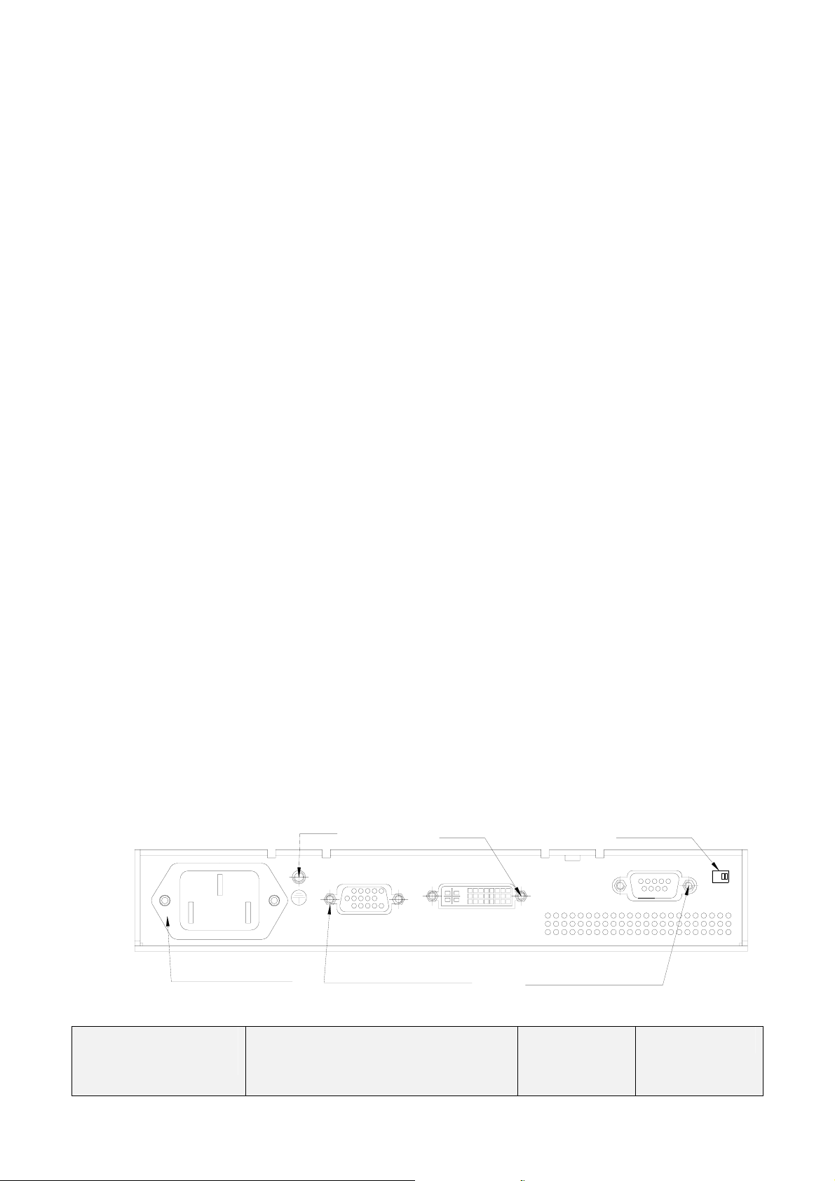
2.3 Signal Interface
Last change: 27
th
ON Pulses ON ON Active <54W Green
N/A N/A Blanked <2W Orange
Pulses
IN LET 3P IEC TYPE
Copyright @ SSME (SIEMENS
, Oct. 2005
Medical Equipment Ltd.) All
GND
15-PIN MIN D-TYPE VGA
FEMALE CONNECTOR
DVI-D
5V SWITCH
9-PIN D-SUB RS-232
FEMALE CONNECTOR
HL1916
Page 5 of 32
ONOFF
rights reserved
2.3.1 Signal Specifications
Item SPEC
Analog:
Frequency
Signal Input
(Analog)
D-SUB
CVS Signal
DVI-I Input Via DVI-I to VGA connector
DVI-D Input
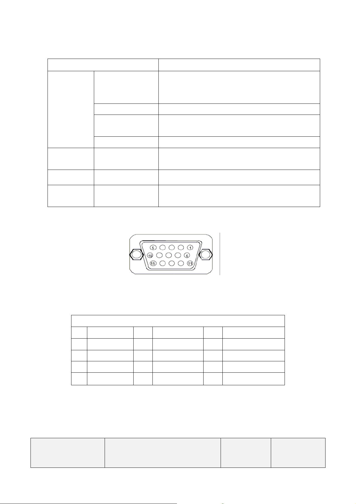
2.3.2 D-SUB Connector and Pin Assignment (Figure1)
Pixel clock 25--165MHz
Video Input
Signal Input Separate Sync, TTL (N or P)
H 30 ~ 82kHz
V 50 ~ 85Hz
Analog 0.7Vpp
Input Impedance 75 Ohm
Video Level: 0.5---1.0V
Sync level: 0.2---0.3V
DVI-Digital
DDC via DVI
Last change: 27
Figure 1
15-pin Min D-type Female Connector
Table 1
Pin - Assignment of 15-pin D-sub:
1 Red Video 6 Red Ground 11 Monitor Ground
2 Green Video 7 Green Ground 12 DDC-Serial Data
3 Blue Video 8 Blue Ground 13 H-Sync.
4 N/C 9 NC 14 V-Sync.
5 GND 10 Logic Ground 15 DDC-Serial Clock
th
, Oct. 2005
Copyright @ SSME (SIEMENS
Medical Equipment Ltd.) All
HL1916
rights reserved
Page 6 of 32
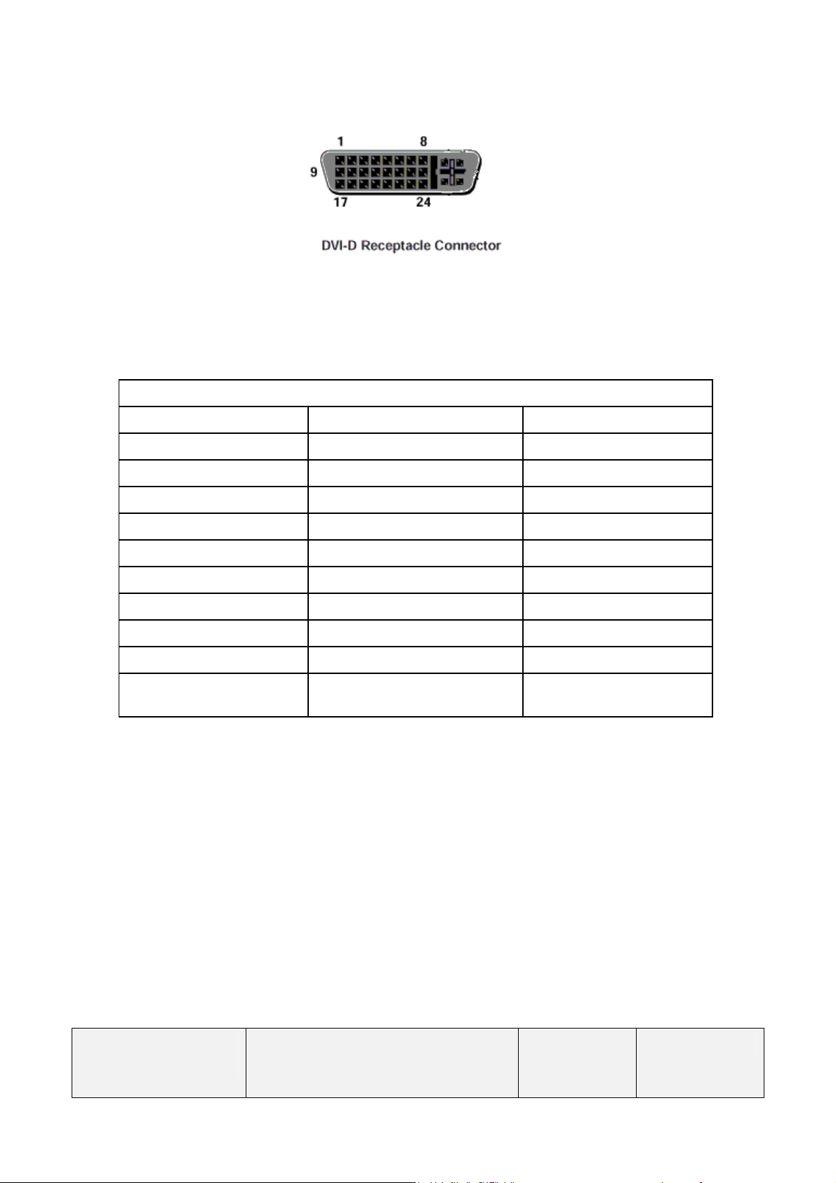
2.3.3 Digital Visual Interface and Pin Assignment (DVI)
Figure 2
29-pin DVI-D Female Connector
Table 2
Pin - Assignment of 29-pin DVI-D/DVI-I Female Connector
Pin 1 - TMDS Data 2- Pin 12 - TMDS Data 3- Pin 22 - TMDS Clock Shield
Pin 2 - TMDS Data 2+ Pin 13 - TMDS Data 3+ Pin 23 - TMDS Clock+
Pin 3 - TMDS Data 2/4 Shield Pin 14 - +5 V Power Pin 24 - TMDS ClockPin 4 - TMDS Data 4- Pin 15 – Ground
Pin 5 - TMDS Data 4+ Pin 16 - Hot Plug Detect
Pin 6 - DDC Clock Pin 17 - TMDS Data 0-
Pin 7 - DDC Data Pin 18 - TMDS Data 0+
Pin 8 - Analog Vertical Sync Pin 19 - TMDS Data 0/5 S h ield
Pin 9 - TMDS Data 1- Pin 20 - TMDS Data 5-
Pin 10 - TMDS Data 1+ Pin 21 - TMDS Data 5+
Pin 11 - TMDS Data 1/3
Shield
2.3.4 Control Interface
Beside the OSD, we also support RS-232 interface to update and control the monitor by
software. When the monitor is connected with a CT or other iatrical diagnosis instruments, we
provide additional interface for the service technician to get the status of the monitor and update
software. When use RS-232 for software update, first put 5V switch (near the RS-232 input) to on
position. And then load the soft ware from computer. After complete software update, slide the
switch to off position. And then power off the monitor. Power on again the software update is
completed.
Last change: 27
th
, Oct. 2005
Copyright @ SSME (SIEMENS
Medical Equipment Ltd.) All
HL1916
Page 7 of 32
rights reserved
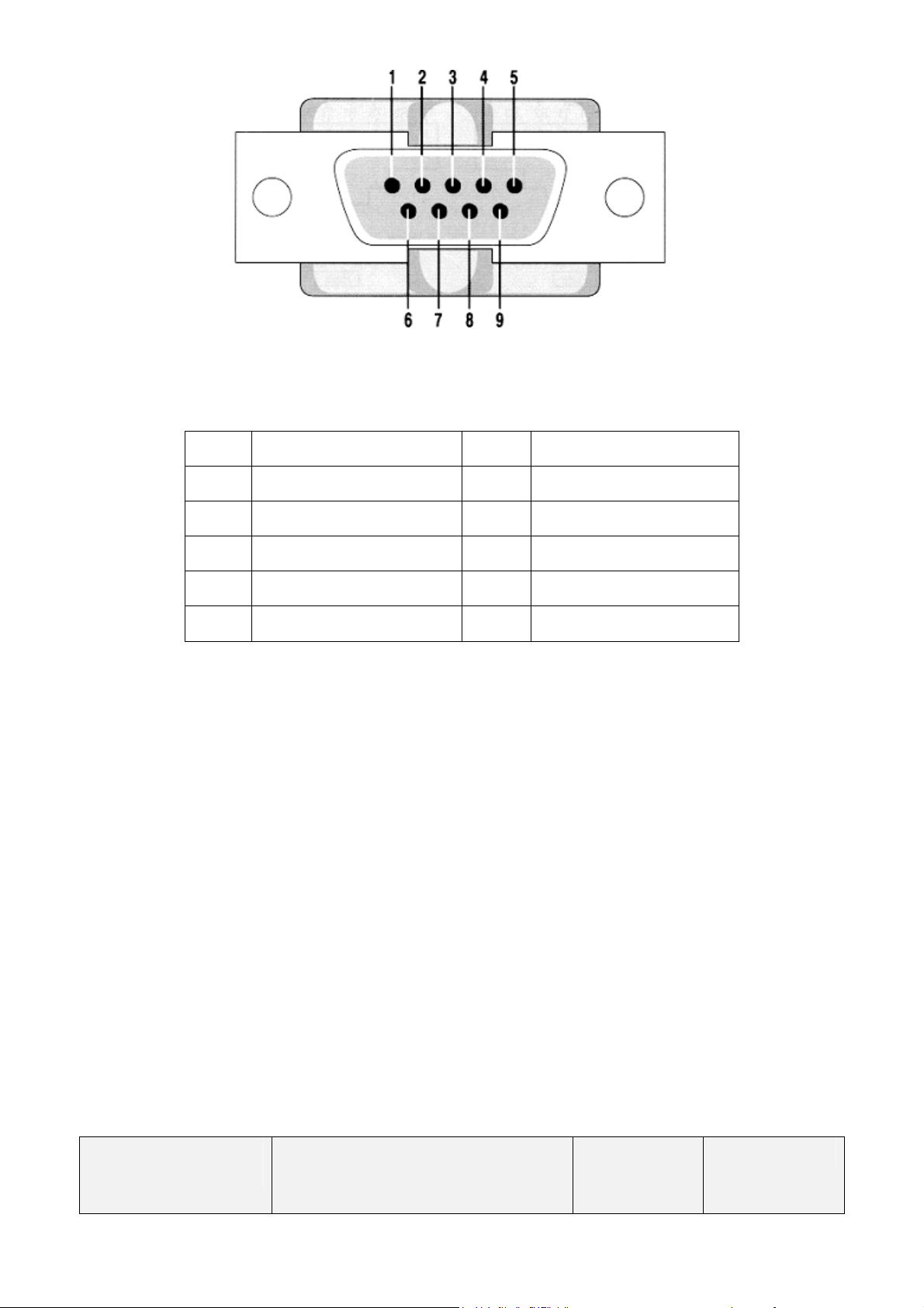
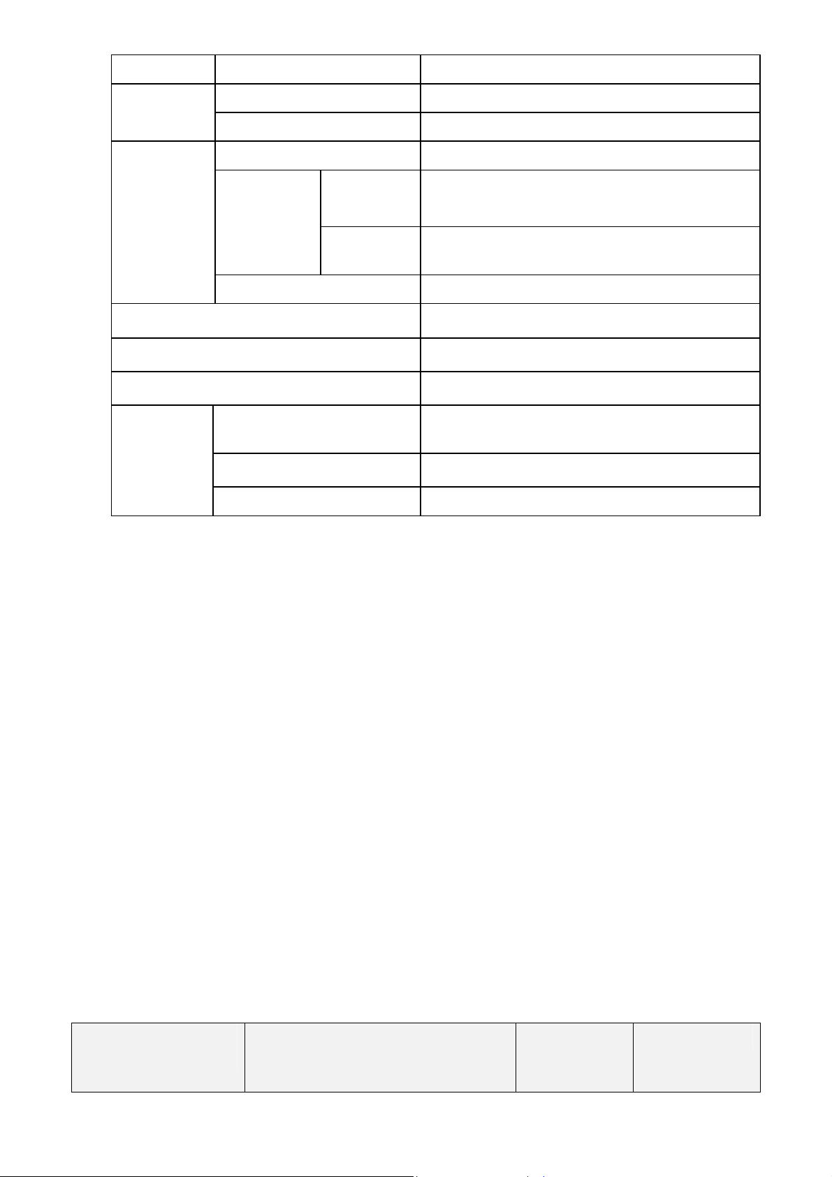
Figure 3 Female 9-PIN D-SUB connector
Table3
Pin Signal Pin Signal
1 Data Carrier Detect 6 Data Set Ready
2 Received Data 7 Request to Send
3 Transmitted Data 8 Clear to Send
4 Data Terminal Ready 9 Ring Indicator
5 Signal Ground
Last change: 27
th
, Oct. 2005
Copyright @ SSME (SIEMENS
Medical Equipment Ltd.) All
rights reserved
HL1916
Page 8 of 32
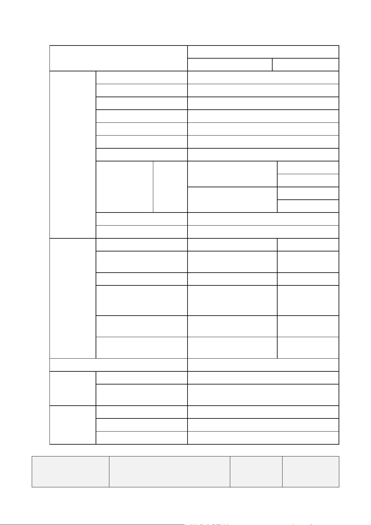
2.4 Product Features
Item
LCD
Specification
Analog Input Digital Input
Panel Module LG.PHILIPS LM190E05-SL02
Size 19.0” (48 cm diagonal)
Active Display Area 376.32 (H) x 301.056 (V) mm
Resolution 1280 x 1024 dots (SXGA)
Pixel Pitch 0.294(H) x 0.294(V) mm
Color Depth 16.7M true 8 bit
Luminance 280 cd/m2 (typical); 230cd/m2 (min.)
Viewing Angle
(Type.)
H
L 89 degree
R 89 degree
CR>10
H 89 degree
V
L 89 degree
Contrast Ratio 600:1 (typical); 400:1 (min.)
Back Light CCFL x 6pcs.
Horizontal frequency 31kHz -82kHz 31kHz -82kHz
Vertical frequency
50.0Hz - 85.0 Hz
(Non-Interlaced)
50.0Hz - 85.0 Hz
(Non-Interlaced)
Video Signal Analog RGB Digital RGB
Input
Signals
Sync. Signal
Separate Sync. (TTL)
Composite Sync.
TMDS
Sync on green
Pixel Clock 25.0MHz -165.0MHz
Input connector Mini D-sub 15Pin
25.0MHz
-165.0MHz
DVI-I (D) &
DVI-D
Preset Timings Factory preset: 39 / User preset: 10 *
Control key Select, up, down, exit
Functions
Regulations
OSD
Safety IEC60601-1, CCC
Backlight Brightness, Contrast, Color control,
Position, Size, Phase, Gamma, etc.
EMC IEC60601-1-2
Last change: 27
th
, Oct. 2005
Power Management VESA DPMS, EPA,
Copyright @ SSME (SIEMENS
HL1916
Medical Equipment Ltd.) All
rights reserved
Page 9 of 32
Plug and Play VESA DDC2B
Temperature 5-40 degree C Environment
Condition
Humidity 30-80% (without condensation)
Input Voltage AC100-240V, 50 / 60Hz; <0.5A
<54W
<2W
Power
Supply
Power
Consumption
Normal
operation
Power
saving
Input Connector 3P IEC Type
VESA compatible arm mounting interface
100mm x 100mm
Height up/down 60mm—80mm (around)
Tilt adjust Up & Down –5--15 degree
Accessories
AC Power cord (Extension
Type)
Signal Cable 3.0 m: D-sub15pin VGA; 3.0 m: DVI-D
3.0 m
Others User’s manual, DVI-I to VGA connector
Remark: The monitor shall recognize preset modes within a range of ±1KHz for horizontal and
±1Hz for vertical. (See appendix 1)
2.5 Screen Performance
2.5.1 Standard Testing Conditions
- Warm up time
≥ 20
minutes.
- AC supply voltage 100-240VAC, 50/60Hz
- Ambient temperature
- Relative Humidity 30% --80%
20°C -25°C
- Video signal 1280 x 1024 @ 60Hz; DVI-D
- Ambient Environment Dark
- Setting Set to Gamma CIE factory preset
- Luminance meter Minolta CA-210
Last change: 27
th
, Oct. 2005
Copyright @ SSME (SIEMENS
Medical Equipment Ltd.) All
rights reserved
HL1916
Page 10 of 32

2.5.2 Brightness
Factory Preset (Gamma CIE) : Lmin = 0.36+0.15/-0.1 cd/m²
Lmax = 137+5/-5 cd/m²
Factory Preset (DICOM) : Lmin = 0.45+0.15/-0.1 cd/m²
Lmax = 137+5/-5 cd/m²
Max. Brightness: ≥230cd/m2 (adjust CCFL, Contrast and Brightness to Maximum)
Test Condition: White Luminance (L max) is defined as a luminance of L255 Gray
Level at the center point on LCD surface. Also Black Luminance (L
min
) is defined as a Luminance of L0 Gray level at the center point on
LCD surface. (See Note 1 Note 4)
2.5.3 View angle
Left/Right and Up/Down typical 178 degree (CR≥10) (Note 2)
2.5.4 Brightness Uniformity
Deviation less than 20% (Note 5)
Comply with DIN6868-57 Class B
2.5.5 Contrast radio
Over 400:1 (note 3)
2.5.6 White Color Coordinates
X=0.313 ± 0.03
Y=0.329 ± 0.03
(Note 7)
2.5.7 Response Time
Typical (Tr+Td): 18ms (Note 6)
2.5.8 Color Gray
64 gray level should seen clearly
256 gray levels should be seen smoothly
Last change: 27
th
, Oct. 2005
Copyright @ SSME (SIEMENS
Medical Equipment Ltd.) All
rights reserved
HL1916
Page 11 of 32

2.5.9 Gamma Curve
Within ± 10% tolerance of calculated value
Factory Preset gamma value: Gamma CIE; DICOM; Gamma 2.0; 2.2; 2.4; NATIVE
(Gamma CIE is default setting)
Note1: Test Equipment Setup
The measurement should be executed in a stable, windless and dark room between
20 minutes after the backlight at the given temperature for stabilization of the backlight.
This should be measured in the center of screen. Test equipment should be equivalent
with the following equipment.
Environment condition: Ta=25±2°C
Last change: 27
th
, Oct. 2005
Copyright @ SSME (SIEMENS
Medical Equipment Ltd.) All
rights reserved
HL1916
Page 12 of 32

Note2: Viewing angle is measured as follow:
Note 3: Definition of contrast Ratio (CR):
Ratio of gray max (Gmax) & gray min (Gmin) at the center point of the panel.
Gmax: Luminance with all pixels white
Gmin: Luminance with all pixels black
Note 4: Definition of Luminance of White: Luminance of white at center point.
Note 5: Definition of brightness uniformity
Bmax: Maximum brightness
Bmin: minimum brightness
Last change: 27
th
, Oct. 2005
Copyright @ SSME (SIEMENS
Medical Equipment Ltd.) All
rights reserved
HL1916
Page 13 of 32

Note 6: Definition of response time is as follows:
Sum of TrD, TfR
When the display data is changed from white to black, response time is
measured
Optical
Response
100
90
10
0
white
TrD TrR
black
Note 7: Definition of Color Chromaticity (CIE 1931)
Color coordinate of Red , Green, Blue & White at center point .
3. OPERATING GUIDE
3.1 Keys assignment
white
Last change: 27
th
, Oct. 2005
LED
MENU
UP
DOWN
SET
Figure 4
Copyright @ SSME (SIEMENS
Medical Equipment Ltd.) All
rights reserved
HL1916
Page 14 of 32

3.2 Key Functions without active OSD Menu
Key Action
Menu Activate OSD
Up Select VGA (DVI-A) input source
Down Select DVI-D input source
Note: This choice is in case all the signal sources are available. If not, the signal on the any one
input will be displayed.
3.3 Key Functions in the OSD Menu
Keys Situation Action
Menu Always Jump to next line
Slide controller Increase Value Up
Command “Enter Key”
Down Slide controller Decrease value
Set
Except “Exit OSD” Menu One menu level upwards
(Settings are retained)
In “Exit OSD” Menu Return to main menu
(Settings are retained)
3.4 Submenu Calls
Press the “Menu” key while the OSD is active, the function icon will jump to next line.
Pressing the “Up” key, the coordinate submenu will be selected.
3.5 Locking of OSD Menu
Keys Action
1 time Set key
3 times Up key
within 3 seconds
Lock or unlock OSD
If the OSD is locked, it is only possible to
select input source (see 3.1 section).
3.6 Description of OSD Menu
Last change: 27
th
, Oct. 2005
Copyright @ SSME (SIEMENS
Medical Equipment Ltd.) All
rights reserved
HL1916
Page 15 of 32

Main Menu Function
Brightness 0…100%
Contrast 0…100%
Brightness
/Contrast
Backlight
Color
Adjustment
range
0…100%
Recommended
setting Max. 80%
1,2,3 User
1, 9300K
2, 7300K
3, 6500K
User define
Description
It is used to adjust the black level of the
monitor.
This allows the darker area to be seen more
distinctly.
Note: for DVI-D signals the brightness
setting is optimized. Manual changes are
not recommended.
Adjustment of contrast
This allows the brighter area to be seen
more distinctly.
Note: for DVI-D signals the Contrast
setting is optimized. Manual changes are
not recommended.
Adjustment brightness of LCD backlight to
adapt total brightness for room illumination
Set desired color or Hue
Three fixed color temperatures and one
adjustable color temperature are available
The color locations 1 to 3 can not be saved
Position
Picture Source
Auto function
(Analog input
only)
Set user
color
Red Gain
Green Gain
Blue Gain
H Position 0…100% Shift picture in horizontal direction
V Position 0…100% Shift picture in vertical direction
-32…+32
VGA (DVI-A)
DVI-D
Define user color temperature
Select Red, Green, Blue gain separately
Select source for main display
When you enter this OSD menu the current
source is highlighted.
Following switch off and on of the display,
the picture sources are searched one after
another.
The auto functions are used to assist the
automatic setting of parameters. The quality
of settings depends on the picture contents
and the type of synchronization.
Corresponding items in the OSD can adjust all
settings finely.
Last change: 27
th
, Oct. 2005
Copyright @ SSME (SIEMENS
Medical Equipment Ltd.) All
rights reserved
HL1916
Page 16 of 32

y
Auto
brightness
/contrast
On/Off
Automatically get input signal match with the
monitor
Language
Auto
position
/phase
On/Off
/frequency
Execute
selected
auto
function
English
Chinese
Frequency
/Phase
Sharpness
Interpolation filter
1 to 7
Automatically adjusts the image position,
H-Size (or V-Size) and Fine settings. Improve
focus clarity and image stability.
The selected auto functions are executed.
Note: The quality of the function depends on
the applied picture contents. To get better
effect it is recommended to apply full screen
and including whiteness contents picture.
Select the language of OSD menu.
Note: English menu is default state.
You can make further settings for the
picture source
Adjust the frequency and phase of the input
signal.
One of the 7 filters can be selected for the
focus setting to reduce scaling artifacts.
Interpolation filters depend on the input
resolution. A filter is not usually used with
1280X1024 since each pixel is controlled
by its own pulse. The user should
individually adjust the filter depending on
the application.
Adjustment of OSD horizontal position
Others
OSD setting
H position
V position
Adjustment of OSD vertical position
(Default state is on the bottom right corner
of the screen)
DPMS
setting
DPMS on
The backlight is switched off while it is no
input signal. (The default state is DPMS
on)
The backlight will not switch off if it is no input
DPMS off
Status
signal. Only switches off along with the power
switches off.
Current display settings can be called here
in the respective picture mode.
Working hours of display, firmware type
and version, OSD version, configuration
version, current source, current timing of
input signal, current LUT
Service level 2 Settings in this menu must only be carried out by service person*
Quit OSD
menu
Accept changes
Reject changes
Quick OSD menu and either save or reject
the changes.
If you have reached this menu
unintentionall
, you can return to the main
Last change: 27
th
, Oct. 2005
Copyright @ SSME (SIEMENS
Medical Equipment Ltd.) All
rights reserved
HL1916
Page 17 of 32

menu using the Set key.
Note: if the OSD menu is quit by changing
the timing or by switching off the monitor,
the modification you have made are saved.
OSD is
locked
* Service level 2 enter: while the highlight line is on the service level 2 position, press 1 x Up, and 2
x Down keys, it will enter the following submenu.
Service level 2 For LUT select and factory settings recall: Brightness; Contrast; Backlight; Color
3, 6500K; OSD position. (The default state is Gamma CIE)
Gamma CIE Select Gamma CIE LUT
DICOM Select DICOM LUT
Gamma 2.0 Select Gamma 2.0 LUT
Gamma 2.2 Select Gamma 2.2 LUT
Gamma 2.4 Select Gamma 2.4 LUT
Native Select panel native characteristics
If this message is displayed, you do not
have the authority to carry out th e changes
in the OSD menu.
Please contact your servicing partner in this
case.
4. MECHANICAL SPECIFICATIONS
4.1 Outline dimensions & weight
SIEMENS
Figure 5
Last change: 27
th
, Oct. 2005
Copyright @ SSME (SIEMENS
Medical Equipment Ltd.) All
rights reserved
HL1916
Page 18 of 32

Item Set
Width 425mm
Size of set
Tilt 0 degree – 20degree
Housing components Aluminum
Kensington lock Yes
Visible screen surface
Ventilation slots In rear panel
Degree of protection IP20 to DIN40050
Connection panel At rear, covered
Net weight
4.2 Screen Quality
Depth 210mm
Height 493 (-60) mm
Approx. 376mm×301mm
Approximately 5.5 Kg (without stand)
Approximately 8.8 Kg (with stand)
4.2.1 H/V outline position
H: |L-R|≤1.0mm
V: |U-D|≤1.0mm
Last change: 27
th
, Oct. 2005
Copyright @ SSME (SIEMENS
Medical Equipment Ltd.) All
rights reserved
HL1916
Page 19 of 32

4.2.2 Outline edge position
∣A-B∣≤1.0mm ∣C-D∣≤1.0mm
∣E-F∣≤1.0mm ∣G-H∣≤1.0mm
4.2.3 Structure width position
∣A-B∣≤2.0mm
Last change: 27
th
, Oct. 2005
Copyright @ SSME (SIEMENS
Medical Equipment Ltd.) All
rights reserved
HL1916
Page 20 of 32

4.3 Packaging
Figure 6
4.3.1 Package dimension and weight
Box
Width (mm)
Outer size of box
Gross weight Approximately 12.5Kg
Depth (mm)
Height (mm)
5. ENVIRONMENT CONDITONS
5.1 Operation Temperature
Ambient temperature range
Temperature gradient
570
370
575
+5 -- +40℃
Max. 5℃/h, no condensation
Atmospheric pressure 1040 – 674 hPa
Last change: 27
th
, Oct. 2005
Copyright @ SSME (SIEMENS
Medical Equipment Ltd.) All
rights reserved
HL1916
Page 21 of 32

5.2 Transport and storage (Packed)
Ambient temperature range
Temperature gradient
Atmospheric pressure 1040 – 674 hPa (0 -- 3048m)
-20 -- +60℃
Max. 5℃/h, no condensation
5.3 Mechanical requirements
Operation
According to EN60068-2-6
Vibration
Shock
10--58 Hz within ± 0.075 mm deflection
58—500 Hz at 10 m/s2
According to EN 60068-2-27 (single shock)
150m/s2, 6ms
No permanent shock allowed in operating conditions
Packed unit
Vibration
Shock
According to EN60068-2-6
5--9 Hz within ± 3.5 mm deflection
9—500 Hz at 10 m/s2
According to EN 60068-2-27 (single shock)
250m/s2, 6ms(in storage packing)
According to EN 60068-2-29 (permanent shock)
Last change: 27
th
, Oct. 2005
Copyright @ SSME (SIEMENS
Medical Equipment Ltd.) All
rights reserved
HL1916
Page 22 of 32

5.4 Drop Test (packed)
Corner
Edge
Surfaces
(Cushion should be changed to new one.)
Corner
Edge
Position Height
1 76.0cm
3,2,4 76.0cm
A,B,C,D 76.0cm
E 76.0cm
F 76.0cm
5 76.0cm
6,7 76.0cm
Figure 7
5.5 Safety specifications
Safety standards
Approvals
Protection class Protection class 1
Degree of protection to
DIN 40050
Conformity CE
EN60601, IEC601
CAN/CSA – C 22.2 No 601.1 – M 90
CSA/us mark, UL 2601-1
IP 20
Last change: 27
th
, Oct. 2005
Copyright @ SSME (SIEMENS
Medical Equipment Ltd.) All
rights reserved
HL1916
Page 23 of 32

5.6 Electromagnetic compatibility
5.7 MTBF
Flat screen without Backlight: 50,000 operation hours.
Flat screen with Backlight: 10,000 operation hours.
Last change: 27
th
, Oct. 2005
Copyright @ SSME (SIEMENS
Medical Equipment Ltd.) All
rights reserved
HL1916
Page 24 of 32

6. DEFECT, SCRATCH and DUST
6.1 Condition
These defects are inspected under the following conditions:
Temperature: 20 ~ 25 degrees C
Humidity: 65
Illumination: Single 20W fluorescent lamp non-directive
(Appearance: 300 to 700 LUX)
Viewing distance: The distance between the LCM and the inspector’s eyes shall be at
Viewing angle: The inspection shall be conducted within normal viewing angle range.
6.2 Dot Defect
± 5% RH
least 30cm --50 cm.
Last change: 27
th
, Oct. 2005
Copyright @ SSME (SIEMENS
Medical Equipment Ltd.) All
rights reserved
HL1916
Page 25 of 32

Note 1: a. every dot herein means Sub- Pixel (Each Red, Green, or Blue Color)
b. Damaged less than half size of sub-pixels is not counted as defect
c. Dots darker than half brightness of sub-pixel are not defined as bright dot defect and dots
brighter than half brightness of sub-pixels is not defined as dark dot defect.
d. The definition of range A is included in range B.
Note 2: Panel Pixel Defect comply with ISO 13406-2 class 2
6.3 Polarize Defects
(Unit: mm)
Items Criteria
Scratches Linear 0.02 <= W <=0.05, 1.0<= L <=10.0, N <=5
Dent Circular 0.15<= D <=0.5, N<=5
Where W: Width
L: Length
D: Average diameter = (a + b) / 2
:
Note
a. Average Diameter
b. Linear: a>2b, Circular: a<=2b
c. Extraneous substances which can be wiped out, like Finger Print, Particles,
are not considered as a defect.
d. Defect which is on the black matrix (outside of Active Area) are not considered as a defect.
6.4 Foreign Material
(Unit: mm)
Items Criteria
Linear 0.02<= W <=0.1, 0.3<= L <=3.0, N <=5 Foreign
Material
Last change: 27
th
, Oct. 2005
Copyright @ SSME (SIEMENS
Medical Equipment Ltd.) All
Circular
0.2<= D <=0.5, N<=5
HL1916
rights reserved
Page 26 of 32

Where W: Width
L: Length
D: Average diameter = (a+b)/2
Note)
a. Average Diameter
b. Linear: a>2b, Circular: a<=2b
6.5 Line Defect
All kinds of line defects such as vertical, horizontal or cross are not allowed.
6.6 Others
Issues, which are not defined in these criteria, shall be discussed with both parties,
Customer and Supplier, for better solution.
7. NOTICE FOR HANDING
7.1 Handing
(1) When the module is assembled, it should be attached to the system firmly using all mounting
holes. Be careful not to twist or bend the modules.
(2) Because the inverters use high voltage, power should be disconnected before it is assembled or
disassembled.
(3) Refrain from string mechanical shock and /or any force to the module. In addition to damage,
this may cause improper operation or the module and CCFT backlight.
(4) Note that polarizers are very fragile and could be easily damaged. Do not press or scratch the
surface using the harder than a HB pencil lead.
(5) Wipe off water droplets or oil immediately. If you leave the droplets for a long time, staining
and discoloration may occur.
(6) If the surface of the polarizer is dirty, clean it using some absorbent cotton or soft cloth.
(7) The desirable cleaners are water, IPA (Isopropyl Alcohol) or Hexane. Do not use Ketone type
materials (ex. Acetone), Ethyl alcohol, Toluene, Ethyl acid or Methyl chloride. It might damage
to the polarizer due to chemical reaction.
Last change: 27
th
, Oct. 2005
Copyright @ SSME (SIEMENS
Medical Equipment Ltd.) All
HL1916
rights reserved
Page 27 of 32

(8) If the liquid crystal material leaks from the panel, it should be kept away from the eyes or mouth.
In case of contact with hands, legs or cloths, it must be washed away thoroughly with soap.
(9) Protect the module from static which may cause damage to the CMOS Gate Array IC.
(10) Use fingerstalls wit h soft gloves in order to keep display clean during th e incoming inspection
and assembly process.
(11) Do not disassemble the module.
(12) Do not pull or fold the lamp wire.
(13) Do not adjust the variable resistor located on the module.
(14) Protection film for polarizer on the module should be slowly peeled off just before use so that
the electrostatic charge can be minimized.
(15) Pins of I/F connector should not be touched directly with bare hands.
Last change: 27
th
, Oct. 2005
Copyright @ SSME (SIEMENS
Medical Equipment Ltd.) All
rights reserved
HL1916
Page 28 of 32

Appendix 1 Preset Timings
Last change: 27
th
, Oct. 2005
Copyright @ SSME (SIEMENS
Medical Equipment Ltd.) All
rights reserved
HL1916
Page 29 of 32

Analog Signal Timings
NO Timing
1024*768@43
1
2
3
4
5
6
7
8
HZ
1024*768@60
HZ
1024*768@70
HZ
1024*768@75
HZ
1024*768@85
HZ
1024*768@60
HZ
1024*768@72
HZ
800*600@56
HZ
Dot
freq
(Mhz)
44.900 35.522 22.806 1.247 3.920 86.958 10.810 0.296 0.056 P P YES
65.000 48.363 15.754 2.462 2.092 60.004 15.880 0.600 0.124 N N NO
75.000 56.476 13.653 1.920 1.813 70.069 13.599 0.513 0.106 N N NO
78.750 60.023 13.003 2.235 1.219 75.029 12.795 0.466 0.050 P P NO
94.500 68.677 10.836 2.201 1.106 84.997 11.183 0.524 0.044 P P NO
MAC
IBM
36.000 35.156 22.222 3.556 2.000 56.250 17.067 0.626 0.057 P P NO
H.freq
(Khz)
H.dis
(us)
H.bac
k
porch
(us)
Hs
width
(us)
V.freq
(Khz)
V.dis
(us)
V.back
porch
(us)
Vs
Wid
(us)
Hs.
Vs
pol
Inte
rlac
e
9
10
11
12
13
14
15
16
17
18
800*600@60
HZ
800*600@72
HZ
800*600@75
HZ
800*600@85
HZ
832*624@75
HZ
640*480@60
HZ
640*480@72
HZ
640*480@75
HZ
640*480@85
HZ
640*480@66
HZ
40.000 37.879 20.000 2.200 3.200 60.317 15.840 0.607 0.106 P P NO
50.000 48.077 16.000 1.280 2.400 72.188 12.480 0.478 0.125 P P NO
49.500 46.875
56.250 53.674 14.222 2.702 1.138 85.061 11.179 0.503 0.056 P P NO
MAC
25.175 31.469 25.422 1.907 3.813 59.940 15.253 1.048 0.064 N P NO
31.500 37.861 20.317 4.064 1.270 72.809 12.678 0.739 0.079 N N NO
31.500 37.500 20.317 4.064 1.270 72.809 12.678 1.739 0.079 N N NO
36.000 43.269
MAC
16016
17077
3.232 1.616 75.000 12.800 0.448 0.064 P P NO
2
2.222 1.556 85.008 11.093 0.578 0.069 N N NO
8
Last change: 27
th
, Oct. 2005
Copyright @ SSME (SIEMENS
Medical Equipment Ltd.) All
rights reserved
HL1916
Page 30 of 32

19
640*350@70
HZ
25.175 31.469 25.422 1.907 3.813 70.087 11.122 1.907 0.064 P N NO
20
21
22
23
24
25
26
27
28
29
720*350@70
HZ
640*400@70
HZ
720*400@70
HZ
640*350@85
HZ
720*350@85
HZ
640*400@85
HZ
720*400@85
HZ
1152*864@60
HZ
1152*864@70
HZ
1152*864@75
HZ
25.175 31.469 25.422 1.907 3.813 70.087 12.711 1.112 0.064 N P NO
31.500 37.86 20.317 3.048 2.032 85.080 9.244 1.585 0.079 P N NO
31.500 37.86 20.317 3.048 2.032 85.080 10.565 1.083 0.079 N P NO
35.500 37.927 20.282 3.042 2.028 85.039 10.546 1.107 0.079 N P NO
80.000 54.346 14.400 2.400 1.200 60.053 15.898 0.681 0.055 P P NO
94.200 63.955 12.229 2.038 1.019 70.016 13.501 0.719 0.047 P P NO
108.00 67.500 10.667 2.370 1.185 75.000 12.800 0.474 0.044 P P NO
30
31
32
33
34
35
36
37
38
1152*870@75
HZ
1152*900@66
HZ
1152*900@76
HZ
1280*960@60
HZ
1280*960@85
HZ
1280*1024@
60HZ
1280*1024@
75HZ
1280*1024@
85HZ
1280*768@
60HZ
MAC
21
SUN
108.00 60.000 11.852 2.889 1.037 60.000 16.000 0.600 0.050 P P NO
148.50 85.938 8.620 1.508 1.077 85.002 11.171 0.547 0.035 P P NO
108.00 63.981 11.852 2.296 1.037 60.020 16.005 0.594 0.047 P P NO
135.00 79.976 9.481 1.837 1.067 75.025 12.804 0.475 0.038 P P NO
157.50 91.146 8.127 1.422 1.016 85.024 11.235 0.483 0.033 P P NO
1600*1200@
39
60HZ
Last change: 27
th
, Oct. 2005
162.00 75.000 9.877 1.877 1.185 60.000 16.000 0.613 0.040 P P
Copyright @ SSME (SIEMENS
HL1916
Page 31 of 32
Medical Equipment Ltd.) All
rights reserved

Digital Signal Timings
Last change: 27
th
, Oct. 2005
Copyright @ SSME (SIEMENS
Medical Equipment Ltd.) All
rights reserved
HL1916
Page 32 of 32
 Loading...