

Customer Specification
HL1936SMT-L/R
19 Inch LCD Display
Name Department/Title Date Signature
Last change:
2015-1-23
Copyright @Bigtide
All rights reserved
HL1936(HL1936SMT-L
/R internal) For GE
Page 1 of 37
Change History
Update date Author Page Content
2015/1/23 JinZhonghua A0
Last change:
2015-1-23
Copyright @Bigtide
All rights reserved
HL1936(HL1936SMT-L
/R internal) For GE
Page 2 of 37

CONTENTS
1. SCOPE .................................................................................................5
2. ELECTRICAL PERFORMANCE......................................................6
3. OPERATING GUIDE........................................................................ 16
4. MECHANICAL SPECIFICATIONS................................................21
5. ENVIRONMENT CONDITONS ...................................................... 24
2.1 Power Supply ....................................................................................................... 6
2.2 Power Management .............................................................................................6
2.3 Signal Interface ....................................................................................................6
2.3.1 Signal Specifications.........................................................................................6
2.3.2 VGA Connector and Pin Assignment................................................................7
2.3.3 Digital Visual Interface and Pin Assignment (DVI-D) .....................................7
2.3.4 Control Interface ...............................................................................................8
2.3.5 USB Interface (HL1936SMT-R)....................................................................8
2.4 Product Features ..................................................................................................9
2.5 Screen Performance ........................................................................................... 11
2.5.1 Standard Testing Conditions ...........................................................................11
2.5.2 Brightness ....................................................................................................... 11
2.5.3 View angle ......................................................................................................13
2.5.4 Brightness Uniformity ....................................................................................13
2.5.5 Contrast ratio...................................................................................................13
2.5.6 Response Time................................................................................................ 13
2.5.7 Gamma Curve.................................................................................................13
3.1 Keys assignment ................................................................................................16
3.2 Key Functions without active OSD Menu ......................................................... 16
3.3 Key Functions in the OSD Menu.......................................................................16
3.4 Submenu Calls...................................................................................................17
3.5 Locking of OSD Menu.......................................................................................17
3.6 Description of OSD Menu .................................................................................17
3.7 Factory Default Setting ...................................................................................... 20
4.1 Outline dimensions & weight ............................................................................21
4.2 Screen Quality....................................................................................................22
4.2.1 H/V outline position........................................................................................22
4.2.2 Outline edge position ......................................................................................22
4.2.3 Structure width position..................................................................................23
4.3 Packaging...........................................................................................................23
4.3.1 Package dimension and weight.......................................................................23
5.1 Operation Temperature ......................................................................................24
5.2 Transport and storage (Packed).......................................................................... 24
5.3 Mechanical requirements ................................................................................... 24
5.4 Drop Test (packed)............................................................................................. 25
5.5 Safety specifications ..........................................................................................25
5.6 Electromagnetic compatibility ........................................................................... 26
Last change:
2015-1-23
Copyright @Bigtide
All rights reserved
HL1936(HL1936SMT-L
/R internal) For GE
Page 3 of 37

5.7 MTBF ................................................................................................................26
6. DEFECT, SCRATCH and DUST...................................................... 26
7. NOTICE FOR HANDING ................................................................ 32
Handing....................................................................................................................32
Appendix 1 Preset Timings ........................................................................ 33
Last change:
2015-1-23
Copyright @Bigtide
All rights reserved
HL1936(HL1936SMT-L
/R internal) For GE
Page 4 of 37

1. SCOPE
This document defines the performance requirements for a 19.0-inch TFT LCD
monochrome monitor for medical use. This product is controlled by model name; any
change will be recorded in the list and confirmed by GE.
This high-resolution monochrome display is specifically designed to meet the
rigorous performance standards needed for diagnostic, interventional radiology, and
other medical applications. To guarantee image integrity, features include accurate
signal conversion and a wide range of interfacing options.
This monitor is factory calibrated to achieve DICOM part 3.14 compliance and
Gamma CIE at the factory set point. The luminance stabilization circuit employs a built
in photo sensor to keep the back-light lamps at a constant luminance for consistent
calibration over the life of the display and can control the back light system
automatically to extend the life of the monitor and achieve very short warming up time.
The surface of the monitor has an anti-glare coating to minimize reflection and a hard
coating to reduce scratch.
With the deliberate designed bracket the monitor can stick on the desktop firmly.
The monitor has a glass on the LCD.(HL1936SMT-L)
The monitor has a touch screen on the LCD. (HL1936SMT-R)
Last change:
2015-1-23
Copyright @Bigtide
All rights reserved
HL1936(HL1936SMT-L
/R internal) For GE
Page 5 of 37
2. ELECTRICAL PERFORMANCE
2.1 Power Supply
-Input Voltage
: DC24V 10%
- Current (max) : 2A
- Power Consumption : <50W
2.2 Power Management
Power Management condition and status for ANALOG Input mode
SIGNALS Power State
Horizontal Vertical Video Consumption
ON ON ON Active <50W Green
Active
off
Power Management condition and status for DIGITAL Input mode
OFF ON Blanked
ON OFF Blanked
OFF OFF Blanked
SIGNALS Power State
DE Horizontal Vertical Video Consumption
<5W
LED
Status
Orange
Blinking
LED
Status
ON Pulses ON ON Active <50W Green
Active
off
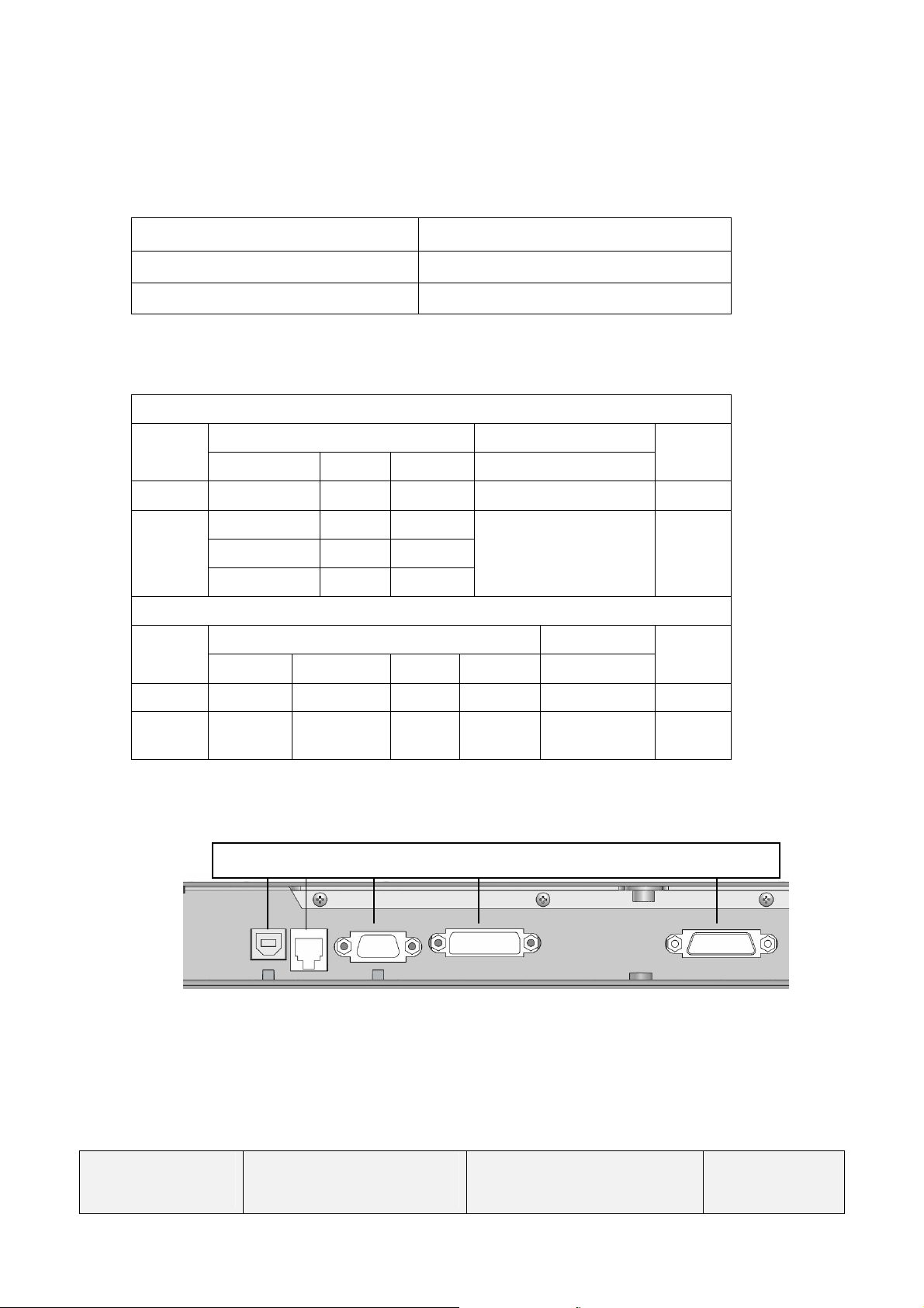
2.3 Signal Interface
2.3.1 Signal Specifications
NO
Pulses
Touch RS232 VGA DVI-D DC Power
N/A N/A Blanked
<5W Orange
Blinking
Last change:
2015-1-23
Copyright @Bigtide
All rights reserved
HL1936(HL1936SMT-L
/R internal) For GE
Page 6 of 37
Item SPEC
Analog:
Frequency
Analog Signal
Input
Digital Signal
Input
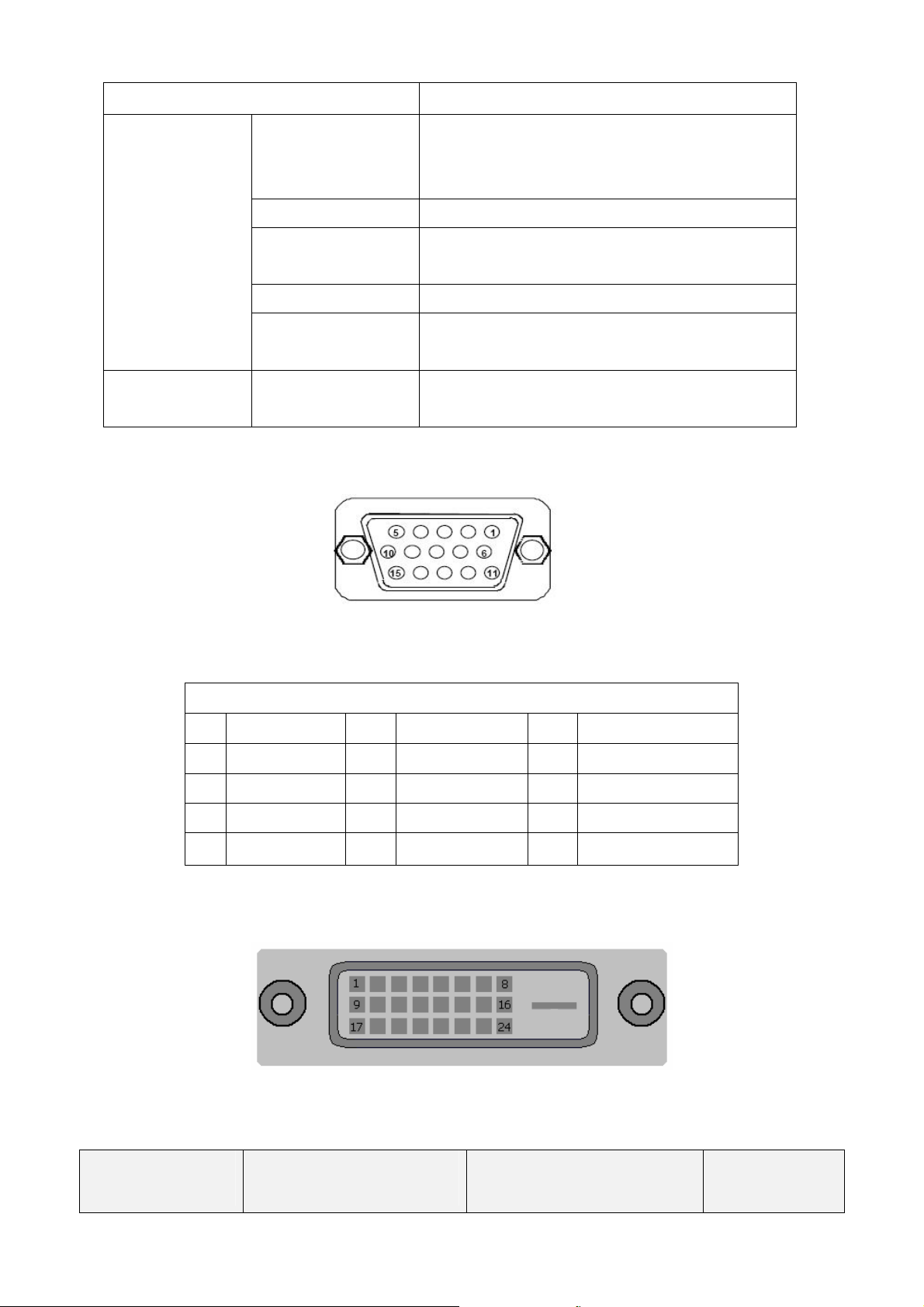
2.3.2 VGA Connector and Pin Assignment
Pixel clock 25--165MHz
Video Input
VGA
Sync Signal Separate Sync, TTL (N or P),SOG
CVS Signal Input
DVI Digital Input
H 30 ~ 82kHz
V 50 ~ 85Hz
Analog 0.7Vpp
Input Impedance 75 Ohm
Video Level: 0.5---1.0V
Sync level: 0.2---0.3V
DVI-Digital
DDC via DVI
Figure 1
15-pin Mini D-type Female Connector
Pin - Assignment of 15-pin D-sub:
1 Red Video 6 Red Ground 11 Monitor Ground
2 Green Video 7 Green Ground 12 DDC-Serial Data
3 Blue Video 8
4 N/C 9 NC 14 V-Sync.
5 GND 10 Logic Ground 15 DDC-Serial Clock
2.3.3 Digital Visual Interface and Pin Assignment (DVI-D)
Blue Ground
13 H-Sync.
Figure 2
25-pin DVI-D Female Connector
Last change:
2015-1-23
Copyright @Bigtide
All rights reserved
HL1936(HL1936SMT-L
/R internal) For GE
Page 7 of 37
Only support DVI single link ,pin 4,5,12,13,20,21 do not work.
Pin - Assignment of 25-pin DVI-D Female Connector
Pin 1 - TMDS Data 2- Pin 12 - TMDS Data 3- Pin 22 - TMDS Clock Shield
Pin 2 - TMDS Data 2+ Pin 13 - TMDS Data 3+ Pin 23 - TMDS Clock+
Pin 3 - TMDS Data 2/4 Shield Pin 14 - +5 V Power Pin 24 - TMDS Clock-
Pin 4 - TMDS Data 4- Pin 15 – Ground
Pin 5 - TMDS Data 4+ Pin 16 - Hot Plug Detect
Pin 6 - DDC Clock Pin 17 - TMDS Data 0-
Pin 7 - DDC Data Pin 18 - TMDS Data 0+
Pin 8 - Analog Vertical Sync Pin 19 - TMDS Data 0/5 Shield
Pin 9 - TMDS Data 1- Pin 20 - TMDS Data 5-
Pin 10 - TMDS Data 1+ Pin 21 - TMDS Data 5+
Pin 11 - TMDS Data 1/3 Shield
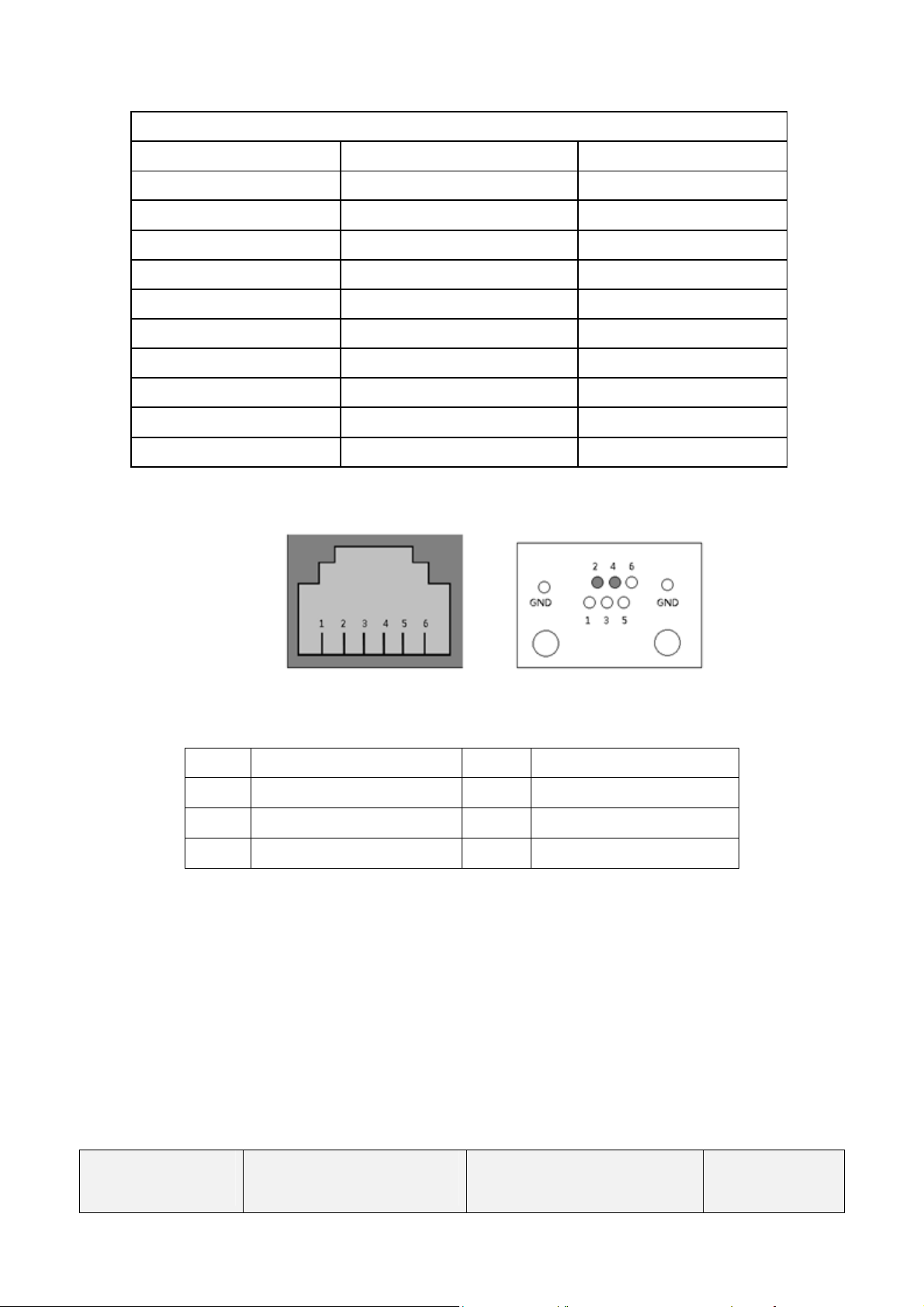
2.3.4 Control Interface
Figure 3
6-pin RJ11 Connector
Pin Signal Pin Signal
1 NC 4 Transmitted Data
2 Received Data 5 NC
3 GND 6 NC
Software update of the display and automatic calibration with external luminance spot meter will be
through this port.
2.3.5 USB Interface (HL1936SMT-R)
The monitor supports touch function ,the touch screen can be used in the Windows and the Linux.
Last change:
2015-1-23
Copyright @Bigtide
All rights reserved
HL1936(HL1936SMT-L
/R internal) For GE
Page 8 of 37
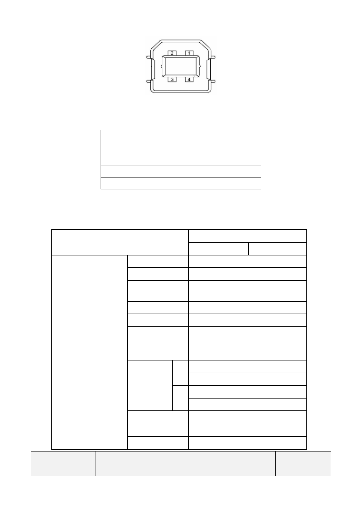
Figure 4
USB-B connector
Pin Signal
1 VBUS
2 D-
3 D+
4 GND
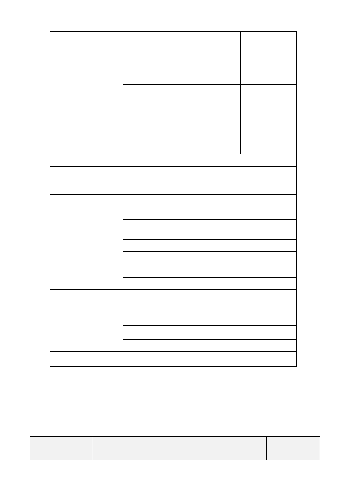
2.4 Product Features
LCD
Item
Specification
Analog Input Digital Input
Panel Module INNOLUX R190EFE-L53
Size 19.0” (48 cm diagonal)
Active Display
Area
376.32 (H) x 301.056 (V) mm
Resolution 1280 x 1024 dots (SXGA)
Pixel Pitch 0.294(H) x 0.294(V) mm
Luminance
Viewing
Angle
(Type.)
CR>10
1400cd/m2 (typical); 1200cd/m2
(min.)
L 85 degree H
R 85 degree
H 85 degree
V
L 85 degree
Contrast Ratio
1000:1 (typical); 800:1 (min.)
Backlight Edge LED
Last change:
2015-1-23
Copyright @Bigtide
All rights reserved
HL1936(HL1936SMT-L
/R internal) For GE
Page 9 of 37
Vertical frequency
Environment Condition
Input Signals
Horizontal
frequency
Video Signal Analog RGB Digital RGB
Sync. Signal
31Hz –82kHz 31kHz -82kHz
50.0Hz - 85Hz
(Non-Interlaced)
Separate Sync.
(TTL) Composite
Sync. Sync
on green
50.0Hz -85 Hz
(Non-Interlaced)
TMDS
Pixel Clock
Input connector Mini D-sub 15Pin DVI-D
Control key Menu, up, down, exit
Functions OSD
Safety IEC60601-1, CCC
EMC IEC60601-1-2
Regulations
Power
Management
Plug and Play VESA DDC2B
Temperature 10-40 ℃
Humidity 10% -80% (non-condensing)
Input Voltage DC24V; <2A
25.0MHz
-165.0MHz
Backlight, Contrast, Brightness level,
Position, Size, Phase, Gamma,
DICOM etc.
VESA DPMS, EPA,
25.0MHz
-165.0MHz
Power
Consumption
Power Supply
Power saving <5W
Input Connector 3W3 FEMALE R/A Type
VESA compatible arm mounting interface
Remark: The monitor shall recognize preset modes within a range of ±1KHz for horizontal and
±1Hz for vertical. (See appendix 1)
Last change:
2015-1-23
Copyright @Bigtide
All rights reserved
Normal operation
<50W
100mm x 100mm
HL1936(HL1936SMT-L
/R internal) For GE
Page 10 of 37
2.5 Screen Performance
2.5.1 Standard Testing Conditions
- Warm up time
- DC supply voltage +24V DC
- Ambient temperature
- Relative Humidity 30%-80%
- Video signal 1280 x 1024 @ 60Hz; DVI-D
- Ambient Environment Dark
- Setting Set to Gamma 2.2 factory preset
- Luminance meter Minolta CA-310 or equivalent
2.5.2 Brightness
2.5.2.1 Factory Settings
Factory Preset (Gamma2.2 default,Gamma1.8,Gamma2.0 ) :
SETTING1: Lmin <1cd/m²
SETTING2: Lmin <1cd/m²
20 minutes.
20C -28C
Lmax =500±20cd/m²
Lmax = 600±20cd/m²
SETTING3: Lmin <1.2cd/m²
Lmax = 700±20cd/m²
Factory Preset (DICOM) : SETTING1:Lmin <1cd/m²
Lmax = 500±20cd/m²
SETTING2: Lmin <1cd/m²
Lmax =600±20cd/m²
SETTING3: Lmin =<1.2cd/m²
Lmax =700±20cd/m²
Factory Preset (CIE) : SETTING1: Lmin <1.5cd/m²
Lmax =500±20cd/m²
SETTING2: Lmin <1.8cd/m²
Lmax =600±20cd/m²
Last change:
2015-1-23
Copyright @Bigtide
All rights reserved
HL1936(HL1936SMT-L
/R internal) For GE
Page 11 of 37

SETTING3: Lmin<2cd/m²
Lmax = 700±20cd/m²
Max. Brightness: ≥800cd/m2 (adjust Backlight, Contrast and Brightness to Maximum)
Test Condition: White Luminance (L max) is defined as a luminance of L255 Gray
Level at the center point on LCD surface. Also Black Luminance (L
min) is defined as a Luminance of L0 Gray level at the center point on
LCD surface. (See Note 1 Note 4)
2.5.2.2 Gamma Curve Description
Li=L0 + (i/255)
Li is the desired luminance of graylevel i.L0 is the luminance of graylevel 0.
L255 is the luminance of graylevel 255.
gammax
(L255-L0)
2.5.2.3 Dicom Formulas
Ji=J0+(J255-J0)/255; Li=10^L(Ji)
Ji is graylevel is JNDs. Li is the desired luminance of graylevel i.
2.5.2.4 CIE Formula
Li= ((100*i/255+16)/116) ^3*L255,
Li is the desired luminance of graylevel i. L255 is the luminance of graylevel 255.
Last change:
2015-1-23
Copyright @Bigtide
All rights reserved
HL1936(HL1936SMT-L
/R internal) For GE
Page 12 of 37

2.5.3 View angle
Left/Right and Up/Down typical 170 degree (CR≥10) (Note 2)
2.5.4 Brightness Uniformity
Deviation less than 30% (Note 5)
2.5.5 Contrast ratio
The panel’s native contrast ratio should be at least 800:1. (Note 3)
2.5.6 Response Time
Typical (Ton +Toff ): 30ms (Note 6)
2.5.7 Gamma Curve
Within ± 10% tolerance of calculated value
Factory Preset gamma value: CIE;DICOM; Gamma1.8, Gamma2.0, Gamma2.2
(Gamma2.2 is default setting)
Note1: Test Equipment Setups
The measurement should be executed in a stable, windless and dark room between 20
minutes after the backlight at the given temperature for stabilization of the backlight.
This should be measured in the center of screen. Test equipment should be equivalent
with the following equipment.
Environment condition: Ta=252C
Last change:
2015-1-23
Copyright @Bigtide
All rights reserved
HL1936(HL1936SMT-L
/R internal) For GE
Page 13 of 37

Note2: Viewing angle is measured as follow:
Note 3: Definition of contrast Ratio (CR):
Ratio of gray max (Gmax) & gray min (Gmin) at the center point of the panel.
Gmax: Luminance with all pixels white
Last change:
2015-1-23
Copyright @Bigtide
All rights reserved
HL1936(HL1936SMT-L
/R internal) For GE
Page 14 of 37

Gmin: Luminance with all pixels black
Note 4: Definition of Luminance of White: Luminance of white at center point.
Note 5: Definition of brightness uniformity
Bmax: Maximum brightness
Bmin: minimum brightness
Note 6: Definition of response time is as follows:
Definition of Response Time (Ton, Toff):
Last change:
2015-1-23
Copyright @Bigtide
All rights reserved
HL1936(HL1936SMT-L
/R internal) For GE
Page 15 of 37

3. OPERATING GUIDE
3.1 Keys assignment
LED
MENU
UP
DOWN
EXIT
Figure3
3.2 Key Functions without active OSD Menu
Key Action
Menu Activate OSD
Down Analog Input auto balance
Note: This choice is in case all the signal sources are available. If not, the signal on the any one
input will be displayed.
3.3 Key Functions in the OSD Menu
Keys Situation Action
Menu Always Jump to next line
Slide controller Increase Value Up
Command “Enter Key”
Down Slide controller Decrease value
Last change:
2015-1-23
Copyright @Bigtide
All rights reserved
HL1936(HL1936SMT-L
/R internal) For GE
Page 16 of 37

the
EXIT
Except “Exit OSD” Menu One menu level upwards
(Settings are retained)
In “Exit OSD” Menu Return to main menu
(Settings are retained)
3.4 Submenu Calls
Press the “Menu” key while the OSD is active, the function icon will jump to next line.
Pressing the “Up” key, the coordinate submenu will be selected.
3.5 Locking of OSD Menu
Keys Action
1 time EXIT key
3 times Up key
within 3 seconds
Lock or unlock OSD
If the OSD is locked, it is only possible to
select input source (see 3.1 section).
3.6 Description of OSD Menu
Main Menu Function Adjustment range Description
Performance
Brightness 0…255
Set brightness.
Adapting the image quality of
darker picture areas. The center
point is in 128 position.
Note:
The brightness settings are
already optimized for digital
signals. Manual changes to these
values are not recommended, as
this can result in an impairment of
picture quality (loss of
grayscales).
Last change:
2015-1-23
Contrast 0…255
Backlight 0…255 It is used to adjust the Brightness
Copyright @Bigtide
All rights reserved
HL1936(HL1936SMT-L
/R internal) For GE
Adjustment of contrast.
This allows the brighter area to
be seen more distinctly. The
center point is in 128 position.
Note: for DVI-D signal
Contrast setting is optimized.
Manual changes are not
recommended.
Page 17 of 37

selected for the sharpness setting
Interpolation filters depend on
adjusted to get sharper image.
The user should individually
of the monitor.
Display
Settings
Color
H Position
(Analog only)
V Position
(Analog only)
Frequency
(Analog only)
Hsync Phase
(Analog only)
Sharpness Interpolation filter -5
Setting1
Setting 2
Setting 3
User
0…255 Shift picture in horizontal
0…255 Shift picture in vertical direction
0…100 Adjust the frequency and phase of
0…63 Source clock phase
to 5
Set desired Brightness level:
Three fixed Brightness level are
available
The default value is:
Setting1: 500cd/m2; Setting2:
600cd/m2; Setting3: 700 cd/m2
While choose setting 1,2,3 state it
will recall factory default Black
level, Contrast, Backlight
direction
the input signal.
One of the 11 filters can be
to reduce scaling artifacts.
Input
Source
DVI-D
VGA
the input resolution. Digital
signals which is used with
1280X1024 resolution can not be
adjusted since each pixel is
controlled by its own pulse.
Other digital signals which is
lower than 1280 x 1024 can be
adjusted. Analog signals can be
adjusted in all supported
resolution.
Negative figure is adjusted to get
softer image and positive figure is
adjust the filter depending on
the application.
Select the active input source
priority.
If you call this OSD menu, the
current source is displayed. If
current source is inactive (NO
sync) and, it will auto search
other port.
Last change:
2015-1-23
Copyright @Bigtide
All rights reserved
HL1936(HL1936SMT-L
/R internal) For GE
Page 18 of 37

Automatically get input
Note: The quality of the
function depends on the
Adjustment of OSD vertical
Auto Adjust
(Analog only)
Auto-Color ON / OFF
signal match with the monitor
Auto-Config ON / OFF Automatically adjust the image
display settings.
Execute The selected auto functions are
executed.
applied picture contents. To get
better effect it is recommended to
apply full screen picture and
including white and dark
contents.
OSD Settings
Information Firmware Version
H position 0 … 255
V position 0 … 255
Background 0 … 12 Select the OSD background
LED ON/OFF
Language
OSD Version
English
中文
Adjustment of OSD horizontal
position
position
transparency
Setting the status of the operation
LED.
Use the "Language" menu to
select the language of the OSD
menu.
English is the default.
While in the English menu state
the ”中文” font means to select to
Chinese menu. And while in
Chinese menu state the “English”
font means to select to English.
Current display status can be
informed。
Service Level 2 Settings in this menu must only be carried out by service person*
Last change:
2015-1-23
Config Version
Power Saving
Input Source
LUT
Working Hours
Copyright @Bigtide
All rights reserved
HL1936(HL1936SMT-L
/R internal) For GE
Page 19 of 37

Exit Reject changes
Accept changes
Quit OSD
* Service level 2 enter: while the highlight line is on the service level 2 position, press 1 x Up, and 2
x Down keys, it will enter the following submenu.
Check reject changes or accept
changes when quit OSD menu.
Service
level2
LUT select and factory settings recall: Contrast; Brightness; Backlight; Setting1;
OSD position; corresponding LUT factory recall. (The default state is
Gamma2.2LUT)
CIE Select Gamma CIE LUT
DICOM Select DICOM LUT
Gamma 1.8 Select Gamma 1.8 LUT
Gamma 2.0 Select Gamma 2.0LUT
Gamma 2.2 Select Gamma 2.2 LUT(default)
3.7 Factory Default Setting
Main Menu Function Default Value
Performance
Display
Settings
(Analog only)
OSD Settings
Brightness 128
Contrast 128
Color Setting1
Sharpness 2
Auto-Color ON Auto Adjust
Auto-Configure ON
Horizontal position 255
Service level 2:
Service Level2
Others:
OSD Menu status: locked
Last change:
2015-1-23
Vertical position 255
Background 2
LED ON
Language English
LUT Settings Gamma 2.2
Advanced Functions
Copyright @Bigtide
All rights reserved
HL1936(HL1936SMT-L
/R internal) For GE
ALC OFF
Hotkey: ON
DICOM Backlight: OFF
Backlight EOL: OFF
Power saving: OFF
Page 20 of 37

4. MECHANICAL SPECIFICATIONS
4.1 Outline dimensions & weight
Last change:
2015-1-23
Figure 4
Item Set
Size of set
Housing components Aluminum
Visible screen surface Approx. 376mm×301mm
Ventilation slots In rear panel
Degree of protection IP20 to DIN40050
VESA mounting 100x100 mm
Net weight Approximately 5.5 Kg (without stand)
Copyright @Bigtide
All rights reserved
Width 425mm
Height 350mm
HL1936(HL1936SMT-L
/R internal) For GE
Page 21 of 37

4.2 Screen Quality
4.2.1 H/V outline position
H: |L-R|≤1.0mm
V: |U-D|≤1.0mm
4.2.2 Outline edge position
∣A-B∣≤1.0mm ∣C-D∣≤1.0mm
∣E-F∣≤1.0mm ∣G-H∣≤1.0mm
Last change:
2015-1-23
Copyright @Bigtide
All rights reserved
HL1936(HL1936SMT-L
/R internal) For GE
Page 22 of 37

4.2.3 Structure width position
∣A-B∣≤2.0mm
4.3 Packaging
4.3.1 Package dimension and weight
Box
Outer size of box
Gross weight Approximately 7.5Kg
Figure 5
Width (mm)
Depth (mm)
Height (mm)
545
195
470
Last change:
2015-1-23
Copyright @Bigtide
All rights reserved
HL1936(HL1936SMT-L
/R internal) For GE
Page 23 of 37

5. ENVIRONMENT CONDITONS
5.1 Operation Temperature
Ambient temperature range 10 to 40 deg. C
Ambient humidity 10% -80% (non-condensing)
Temperature gradient
Altitude 700 to 1060 hPa
Max. 5℃/h , no condensation
5.2 Transport and storage (Packed)
Ambient temperature range -20 -- +60℃
Ambient humidity 5%-90%
Temperature gradient Max. 10 /h, no condensation℃
Altitude 70 – 106 kPa
5.3 Mechanical requirements
Operation
Vibration
Shock
Packed unit
Vibration
Last change:
2015-1-23
According to EN60068-2-6
10--58 Hz within ± 0.075 mm deflection
58—500 Hz at 10 m/s2
According to EN 60068-2-27 (single shock)
150m/s2, 6ms
No permanent shock allowed in operating conditions
According to EN60068-2-6
5--9 Hz within ± 3.5 mm deflection
9—500 Hz at 10 m/s2
Copyright @Bigtide
All rights reserved
HL1936(HL1936SMT-L
/R internal) For GE
Page 24 of 37

According to EN 60068-2-27 (single shock)
Shock
5.4 Drop Test (packed)
Corner
Edge
Surfaces
(Cushion should be changed to new one.)
Corner
Edge
250m/s2, 6ms(in storage packing)
According to EN 60068-2-29 (permanent shock)
Position Height
1 76.0cm
3,2,4 76.0cm
A,B,C,D 76.0cm
E 76.0cm
F 76.0cm
5 76.0cm
6,7 76.0cm
5.5 Safety specifications
Safety standards
Approvals
Last change:
2015-1-23
Copyright @Bigtide
All rights reserved
Figure 6
IEC 60601-1:2005, ANSI/AAMI
ES60601-1:2005 & CSA C22.2
No.60601-1:2008,EN60601-1,EN60601-1-2,
GB4943.1-2011 , GB9254-2008 ,
GB17625.1-2012,FCC Part15
cTUVus, CCC, CB ,FCC
HL1936(HL1936SMT-L
/R internal) For GE
Page 25 of 37

Protection class
Degree of protection to
DIN 40050
Conformity
5.6 Electromagnetic compatibility
5.7 MTBF
Flat screen without Backlight: 50,000 operation hours.
Flat screen with Backlight: 30,000 operation hours.
Protection class I
IP 20
CE
6. DEFECT, SCRATCH and DUST
Last change:
2015-1-23
Copyright @Bigtide
All rights reserved
HL1936(HL1936SMT-L
/R internal) For GE
Page 26 of 37

Last change:
2015-1-23
Copyright @Bigtide
All rights reserved
HL1936(HL1936SMT-L
/R internal) For GE
Page 27 of 37

Last change:
2015-1-23
Copyright @Bigtide
All rights reserved
HL1936(HL1936SMT-L
/R internal) For GE
Page 28 of 37

Last change:
2015-1-23
Copyright @Bigtide
All rights reserved
HL1936(HL1936SMT-L
/R internal) For GE
Page 29 of 37

Last change:
2015-1-23
Copyright @Bigtide
All rights reserved
HL1936(HL1936SMT-L
/R internal) For GE
Page 30 of 37

Other Issues which are not defined in these criteria, shall be discussed with both parties, Customer
and Supplier, for better solution.
Dust between LCD and touch screen :
Items Criteria
L≤5,N≤3 No dust gathered
S≤0.05 Allowed
0.05<S≤0.2 N≤4
0.2<S≤0.3 N≤2
S>0.3 Not Allowed
HL1936(HL1936SMT-L
/R internal) For GE
Last change:
2015-1-23
Dust
Linear(mm)
Circular(mm2)
Copyright @Bigtide
All rights reserved
Page 31 of 37

7. NOTICE FOR HANDING
Handing
(1) When the module is assembled, it should be attached to the system firmly using all mounting
holes. Be careful not to twist or bend the modules.
(2) Because the inverters use high voltage, power should be disconnected before it is assembled or
disassembled.
(3) Refrain from string mechanical shock and /or any force to the module. In addition to damage,
this may cause improper operation or the module and CCFT backlight.
(4) Note that polarizes are very fragile and could be easily damaged. Do not press or scratch the
surface using the harder than a HB pencil lead.
(5) Wipe off water droplets or oil immediately. If you leave the droplets for a long time, staining
and discoloration may occur.
(6) If the surface of the polarizer is dirty, clean it using some absorbent cotton or soft cloth.
(7) The desirable cleaners are water, IPA (Isopropyl Alcohol) or Hexane. Do not use Ketone type
materials (ex. Acetone), Ethyl alcohol, Toluene, Ethyl acid or Methyl chloride. It might damage
to the polarizer due to chemical reaction.
(8) If the liquid crystal material leaks from the panel, it should be kept away from the eyes or mouth.
In case of contact with hands, legs or cloths, it must be washed away thoroughly with soap.
(9) Protect the module from static which may cause damage to the CMOS Gate Array IC.
(10) Use fingerstalls with soft gloves in order to keep display clean during the incoming inspection
and assembly process.
(11) Do not disassemble the module.
(12) Do not pull or fold the lamp wire.
(13) Do not adjust the variable resistor located on the module.
(14) Protection film for polarizer on the module should be slowly peeled off just before use so that
the electrostatic charge can be minimized.
(15) Pins of I/F connector should not be touched directly with bare hands.
Last change:
2015-1-23
Copyright @Bigtide
All rights reserved
HL1936(HL1936SMT-L
/R internal) For GE
Page 32 of 37

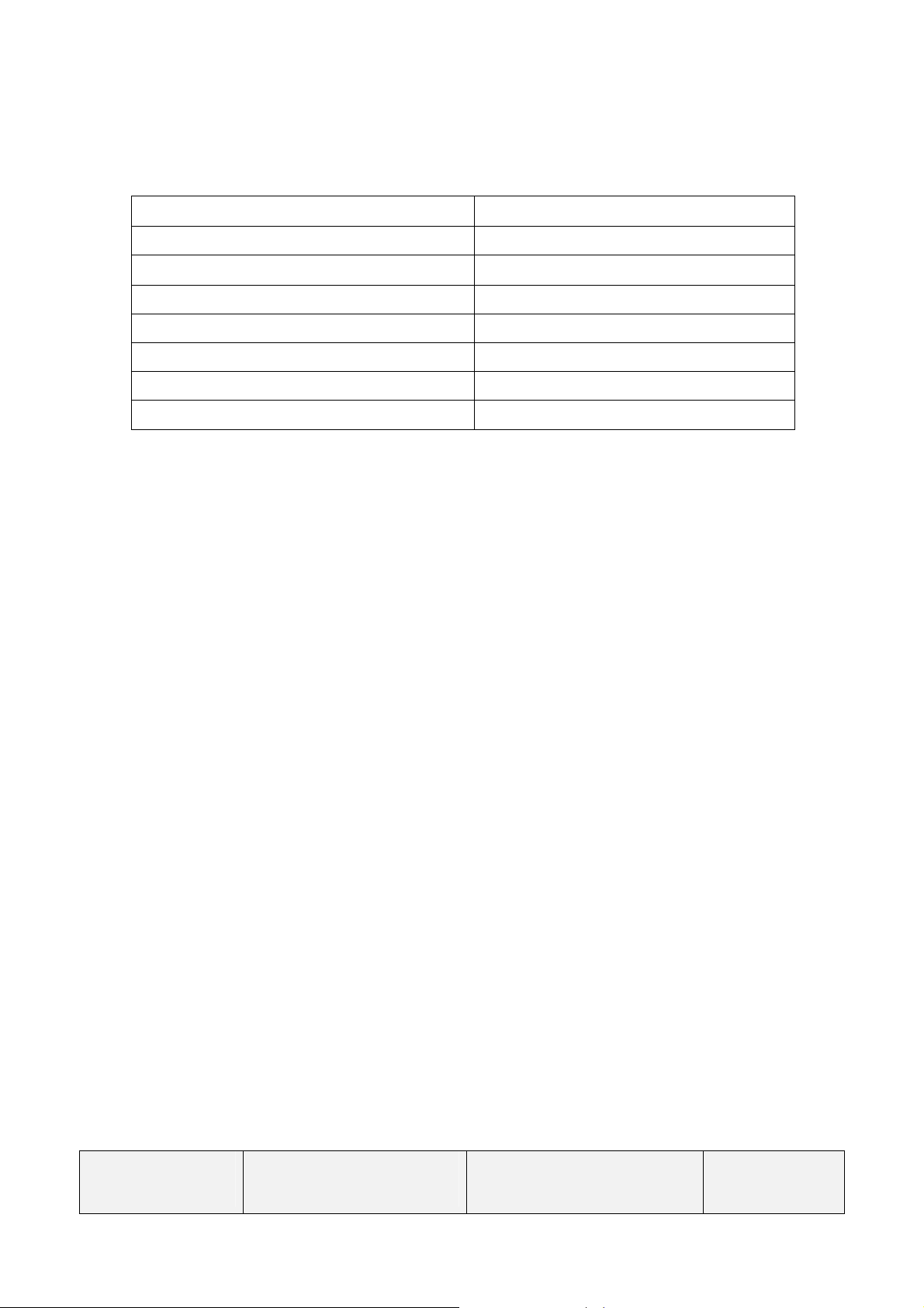
Appendix 1 Preset Timings
Detailed timing comply with VESA specification.
Display Mode
VGA, 720 x 400 31.5 70.1 28.3 -/+
VGA, 640 x 480 31.5 59.9 25.2 -/-
VESA, 640 x 480 37.5 75.0 31.5 -/-
VESA, 800 x 600 37.9 60.3 40.0 +/+
VESA, 800 x 600 46.9 75.0 49.5 +/+
Last change:
2015-1-23
Copyright @Bigtide
All rights reserved
Horizontal
Frequency (kHz)
Vertical
Frequency (Hz)
Pixel Clock
(MHz)
HL1936(HL1936SMT-L
/R internal) For GE
Sync Polarity
(Horizontal/Vertical)
Page 33 of 37

VESA, 1024 x 768 48.4 60.0 65.0 -/-
VESA, 1024 x 768 60.0 75.0 78.8 +/+
VESA, 1152 x 864 67.5 75.0 108.0 +/+
VESA, 1280 x 1024 64.0 60.0 108.0 +/+
VESA, 1280 x 1024 76.7 71.96 135.0 +/-
VESA, 1280 x 1024 80.0 75.0 135.0 +/+
Last change:
2015-1-23
Copyright @Bigtide
All rights reserved
HL1936(HL1936SMT-L
/R internal) For GE
Page 34 of 37
 Loading...