


Digital Video Recorder User Manual
1
Table of Contents
Chapter 1 Parameter------------------------------------------------------------------------------------------------------------------- 3
Chapter 2 DVR appearance and construction -------------------------------------------------------------------------------- 4
2.1 Front Panel ------------------------------------------------------------------------------------------------------------------------ 4
2.2 Real Panel ------------------------------------------------------------------------------------------------------------------------- 5
2.3 Mouse Function------------------------------------------------------------------------------------------------------------------- 5
2.4 Remote Control ------------------------------------------------------------------------------------------------------------------- 7
Chapter 3 System Introduction---------------------------------------------------------------------------------------------------- 8
3.1 Main Menu ------------------------------------------------------------------------------------------------------------------------- 8
3.2 Sub Menu ------------------------------------------------------------------------------------------------------------------------- 11
3.3 main menu operation----------------------------------------------------------------------------------------------------------- 12
3.3.1 Video function -----------------------------------------------------------------------------------------------------------------12
3.3.1.1 Record Setup-------------------------------------------------------------------------------------------------------------13
3.3.1.2 Video Playback ----------------------------------------------------------------------------------------------------------14
3.3.1.3 Backup---------------------------------------------------------------------------------------------------------------------16
3.4 Alarm Function ------------------------------------------------------------------------------------------------------------------- 17
3.4.1 Motion Detection ----------------------------------------------------------------------------------------------------------- 17
3.4.2 Camera Masking----------------------------------------------------------------------------------------------------------- 19
3.4.3 Video Lost -------------------------------------------------------------------------------------------------------------------21
3.4.4 Alarm Input ------------------------------------------------------------------------------------------------------------------23
3.4.5 Alarm Output ---------------------------------------------------------------------------------------------------------------- 24
3.4.6 Abnormity -------------------------------------------------------------------------------------------------------------------- 25
3.5 System setup--------------------------------------------------------------------------------------------------------------------- 25
3.5.1 General setup---------------------------------------------------------------------------------------------------------------26
3.5.2 Encode ----------------------------------------------------------------------------------------------------------------------- 27
3.5.3 Network ----------------------------------------------------------------------------------------------------------------------27
3.5.4 Display------------------------------------------------------------------------------------------------------------------------ 30
3.5.5 Account-----------------------------------------------------------------------------------------------------------------------31

Digital Video Recorder User Manual
2
3.5.6 PTZ setup--------------------------------------------------------------------------------------------------------------------33
3.5.7 RS232 ------------------------------------------------------------------------------------------------------------------------ 34
3.5.8 Tour----------------------------------------------------------------------------------------------------------------------------35
3.6 Tool ---------------------------------------------------------------------------------------------------------------------------------35
3.6.1 HDD Management ---------------------------------------------------------------------------------------------------------- 35
3.6.2 Online User ------------------------------------------------------------------------------------------------------------------- 36
3.6.3 TV Adjust ----------------------------------------------------------------------------------------------------------------------36
3.6.4 USB upgrade-----------------------------------------------------------------------------------------------------------------37
3.6.5 Configuration -----------------------------------------------------------------------------------------------------------------37
3.6.6 Maintenance------------------------------------------------------------------------------------------------------------------ 38
3.6.6 Default -------------------------------------------------------------------------------------------------------------------------38
3.6.8 Exit ------------------------------------------------------------------------------------------------------------------------------ 39
3.7 System Information ------------------------------------------------------------------------------------------------------------- 39
3.7.1 HDD Information ----------------------------------------------------------------------------------------------------------- 40
3.7.2 BPS --------------------------------------------------------------------------------------------------------------------------- 40
3.7.3 Log ---------------------------------------------------------------------------------------------------------------------------- 41
3.7.4 Version -----------------------------------------------------------------------------------------------------------------------41
3.8 Control function ------------------------------------------------------------------------------------------------------------------41
3.8.1 Record control -------------------------------------------------------------------------------------------------------------- 41
3.8.2 PTZ control ------------------------------------------------------------------------------------------------------------------43
3.8.3 Color Setting ---------------------------------------------------------------------------------------------------------------- 45
3.8.4 Video display Split---------------------------------------------------------------------------------------------------------46
3.9 Overview of Navigation and Controls ------------------------------------------------------------------------------------ 48
Chapter 4 WEB CLIENT OPERATION-----------------------------------------------------------------------------------------50
4.1 Router forwarding --------------------------------------------------------------------------------------------------------------- 50
4.2 IE Browser Setup----------------------------------------------------------------------------------------------------------------51
4.3 Login---------------------------------------------------------------------------------------------------------------------------- 5755

Digital Video Recorder User Manual
3
Chapter 1
Parameter
Model SY-DW04B/S SY-DW08B SY-DW16B
Main
Processor
High performance embedded microprocessor
Operating
System
Embedded LINUX
System
Control
Mode
Front panel, USB mouse, IR remote control
Input 4 CH BNC 8 CH BNC 16 CH BNC
Video
Output 1 CH BNC & 1 CH VGA
Input 4 CH RCA 4 CH RCA 4 CH RCA
Audio
Output 1 channel
Display Split 1/4 1/4/8 1/4/8/16
Display
Live
Resolution
D1 (PAL:704*576 NTSC:704*480)
Video/Audio
Compression
H.264 / G.722
Recording
Recording
Priority
Manual >Alarm >MD (motion detect)>Schedule
Motion
Detection
Zones: 396(22×18) sensitivity adjustable
Alarm Input 1CH 8CH 4CH
Video Detection
Alarm
Relay Output 1CH 2CH 2CH
Playback
4CH CIF Playback
Resolution(1CH D1
option)
8CH CIF
Playback
Resolution(1ch
D1 option)
16CH CIF Playback
Resolution
Playback
&Backup
Search
Mode
Time、Date、Event、Channel

Digital Video Recorder User Manual
4
Backup
Mode
USB Device / Remote / Local HDD Backup
Zoom Playback with zoom function
Protocol TCP/IP, UDP, DHCP, DNS, PPPOE, DDNS
Network
Remote
Operation
IE control, CMS
Hard Disk
Hard Disk 1 SATA HDD up to 2TB
2 SATA HDD up to 4TB
supported
USB
Interface
2 ports, 1 for mouse control, 1 for backup
Auxiliary Interface
RS485 1x for PTZ control
Power
Supply
DC12 4A
Working
Environment
-10℃~+50℃ / 10~90%RH / 86~106kpa
Dimension 275*230*60mm 375*295*55mm
Environmental
Weight 1.3KG 2.5KG

Digital Video Recorder User Manual
Charpter 2 DVR appearance and construction
2.1 Front Panel
S/N Name Icon Function
PWR
Power indicator light
LINK
Internet indicator light
1
Power indicator
Light
STATUS
Panel key operation indicator light
Sub Menu FUNC
Right-click sub menu
Recorder control
Enter into the interface to select the record mode
Play
Playback or paused mode, click this button to realize
normal playback
Fast play
Various fast speeds and normal playback.
Slow Play
Multiple slow play speeds or normal playback
2
Assistant
Shift Assistant function: PTZ control and image color. In PTZ
3 PTZ PTZ
Assistant function, PTZ control
Activate current control, modify setup, increase/decr
e
Up/down
Increase/decrease numeral, assistant function such as PTZ
Shift current activated control. When playback, click t
h
Left/right
PTZ control
4
Enter
Confirm current operation
5

Digital Video Recorder User Manual
System menu in review window
5 ESC ESC
Close upper interface or controls.
2.2 Real Panel
6

Digital Video Recorder User Manual
S/N Function
1 4/8/16 Channel Video Input
2 1 Channel Video output
3 4 Channel Audio Input
4 1 Channel Audio output
5 1 Channel Line In
6 1 VGA Output
7 USB OTG 2.0 (Only for USB storage device)
8 RJ45
9 4 Channel Alarm input
10 1Channel Alarm output
11 RS-485
12 GND
13 Power switch
14 DV12V Power
2.3 Mouse Function
*
For right-hand mouse
The DVR could be operated by mouse, connect the USB mouse into the USB port in front panel
System pops up password input dialogue box if you have not
logged in.
In real-time monitor mode, you can go to the main menu.
When you have selected one menu item, left click mouse to view
menu content.
Implement the control operation.
Modify checkbox or motion detection status.
Click combo box to pop up drop down list.
Left click
mouse
In input box, you can select input methods. Left click the
corresponding button on the panel you can input numeral/English
character (small/capitalized). Here ← stands for backspace
button. _ stands for space button.
In English input mode: _stands for input a backspace icon and ←
stands for deleting the previous character.
In numeral input mode: _ stands for clear and ← stands for
deleting the previous numeral.
When input special sign, you can click corresponding numeral in
the front panel to input. For example, click numeral 1 you can
input“/” , or you can click the numeral in the on-screen keyboard
directly.
7

Digital Video Recorder User Manual
Implement special control operation such as double click one item
in the file list to playback the video.
Double left
click mouse
In multiple-window mode, double left click one channel to view in
full-window.
Double left click current video again to go back to previous
multiple-window mode.
In real-time monitor mode, pops up shortcut menu: one-window,
four-window, nine-window and sixteen-window, Pan/Tilt/Zoom,
color setting, search, record, alarm input, alarm output, main
menu.
Among which, Pan/Tilt/Zoom and color setting applies for current
selected channel.
If you are in multiple-window mode, system automatically switches
to the corresponding channel.
Right click
mouse
Exit current menu without saving the modification.
In numeral input box: Increase or decrease numeral value.
Switch the items in the check box.
Press middle
button
Page up or page down
Move mouse
Select current control or move control
Select motion detection zone
Drag mouse
Select privacy mask zone.
2.4 Remote Control
Remote Control Keys
S/N Name Icon Function
8

Digital Video Recorder User Manual
1 Window switch
Switch between one-window and multiple-window dis
p
modes.
2 Add ID
Enter DVR No. setting
*999 for Administrator
*DVR No. setting:
Main Menu->Setting->General:
DVR number
3 Numeral keys 0-
9
0-9
Input password, switch channel and input numeral.
PTZ PTZ
In PTZ function: enable PTZ
4
Shift
Click this button to switch between numeral, English
(Small/Capitalized), Chinese
5 Assistant Fn
Support Multi-function: Shift PTZ control manual, Delete
the previous character, Realize special functions
Confirm operation
6 Enter Enter
Go to the main menu
7 ESC ESC
Close upper interface or controls
Activate current control, modify setup,
Up/down
Increase/decrease numeral, assistant function such as
Shift current activated control
8
Left/right
When playback, click these buttons to control playback
Manually stop/start recording, working with direction keys
9 Record REC
In PTZ function: PTZ setting
10 Shortcut Menu Sub Menu
pops up shortcut menu
Playback or paused mode, click this button to realize
Play/Pause
Iris +
In normal playback or pause mode, click this button to reve
r
Reverse/Pause
Iris -
Various fast speeds and normal playback
Fast play
Zoom +
Multiple slow play speeds or normal playback
Slow play
Zoom -
In playback mode, playback the previous video
Play previous
Focus -
In playback mode, playback the next video
11
Play next
Focus +
Chapter 3 System Introduction
3.1 Main Menu
Main Menu
Sub Menu
Function
9

Digital Video Recorder User Manual
Time setting for record, motion detection, external
alarm.
Schedule
Time operated setting per day per week (Period
time for record, receive external alarm signal, motion
detection)
Search
Record enquiry and playback, sorted by video type
(All, alarm, motion detection, all alarm), channels,
time, the result will be displayed in file list, choose the
file to play
10
R- Regular recording file A – Alarming recoding file
M – Motion detection file H-Manual
Record
Backup
Record backup operation and setting
Motion Detection
Include channel, enable/off, sensitive, detection zone,
arming time, output time delay, alarm linkage, PTZ
linkage, pre-recording, patrol setting etc., copy &
paste for same settings
Include channel, enable/off, sensitive, detection zone,
arming time, output time delay, alarm linkage, PTZ
linkage, pre-recording, patrol setting etc., copy &
paste for same settings
Camera Masking
Video Lost
Include channel, enable/off, arming time, output time
delay, alarm linkage, PTZ linkage, pre-recording,
patrol setting etc., copy & paste for same settings
Alarm Input
Include channel, enable/off, alarm input type, arming
time, output time delay, alarm linkage, PTZ linkage,
pre-recording, patrol setting etc., copy & paste for
same settings
Alarm
Alarm Output
Alarm Mode, setting, on/off and status
Abnormity
Abnormity setting, on/off and linkage action (Alarm
output,

Digital Video Recorder User Manual
General
Setting system time, time format, language, recording in
HDD, series number, video system, video output format,
stand-by time, etc.
Encode
Setting audio & video encode mode, frame rate, quality,
etc.
Network
Setting network address, video transmission protocols,
DHCP, etc.
Display
Setting channel name, front output, coding output,
masking, etc.
Account
User group and account
PTZ
PTZ control protocols and bit rate
RS232
Setting series port and bit rate
Setting
Tour
Setting preview, tour time, etc.
HDD Manage
HDD management, delete data and etc.
Note: System will restart after setting HDD
Online Users
Online user management
Tool
TV Adjust
Adjust picture’s up, down, left, right deflate.
11

Digital Video Recorder User Manual
USB Update
File system, U-BOOT , Kernel, Configuration,
Application update,
Maintenance
Save system configuration as a file, easy to save or load
for quick setting.
Configuration
Restart system and delete files.
Default
Restore all to default or partially by selection
Note: Not for user account
Shut Down
User logout, system shutdown, restart, etc...
HDD
Information
SATA interface status, capacity for each HDD and total,
remaining capacity, video start/stop time, etc.
Type: read-write disk, read-only disk, redundancy disk
etc.
BPS
Each channel’s bit rate and occupied HDD capacity per
hour.
12
Log
Display important event log and designate needed log.
Info
Version
Display system hardware, software version and release
date, etc.

Digital Video Recorder User Manual
13
3.2 Shortcut menu
Record
Playback
Record video inquiry and playback
Record
Backup
Record backup operation and setting
Alarm Output
Alarm output setting, on/off and status
Pan/Tilt/Zoom
PTZ control protocols and bit rate
Color Setting
Set hue, brightness, contrast, saturation
TV Adjust
Adjust picture’s up, down, left, right deflate.
Logout
User logout, system shutdown
View
1 / 4 / 8 / 16 channel display
Menu
Mute
Buzzer off

Digital Video Recorder User Manual
3.3 main menu operation
Main menu includes: video function, alarm function, system setup, management tool, system
information.
Note:
All sub-menu setup will be effective by confirming “SAVE”, otherwise ineffective.
When check box is highlighted, it means certain function is selected. If unfilled means not
selected.
Enter main menu method:
1, press ENTER button on the panel to enter main menu directly
2, press Esc button on the panel, select MAIN MENU.
3.3.1 Video function
Note: User should have “Record” authority, HDD should be installed and format properly,
Setting video setup and playback function, including schedule, motion detection, and exterior alarm
setting. Inquire according to video type (ALL, NORMAL, ALARM, MOTION DETECTION), channel,
time. The result will be displayed in a list
14

Digital Video Recorder User Manual
3.3.1.1 Record Setup
When the system boots up, it is in default 24-hour regular mode. You can set record type and
time in schedule interface. Setting at Main menu> Video function> video setting.
Including schedule setting regarding Regular(R) , motion detection video (M), Alarm (A)
Manual (H)
Channel: Please select the channel number first. You can select “all” if you want to set for the
whole channels.
Redundancy: System supports redundancy backup function. You can highlight Redundancy
button to activate this function. Please note, before enable this function, please set at least one HDD
as redundant. (Main menu->Advanced->HDD Management)
Pack Duration: Choose the time slice of video file
Pre-record: record the video previously than motion detection
Video control: single option, “●” means selected, there are “config”, “all the time”, “close” 3
options.
Week day: There are eight options: ranges from Saturday to Sunday and all.
Time period: means current channel is recording in this period. “■” setting regular, motion
detection, alarm, status, it can be single or multiple choices. 6 time periods to set.
Also allows you to copy one channel setup to another. After setting in channel 1, you can click paste
button and turn to channel 2 and then click copy button. You can finish setting for one channel and
then click save button or you can finish all setup and then click save button to memorize all the
settings.
15

Digital Video Recorder User Manual
3.3.1.2 Video Playback
Playback Window
Search Inquiry
File List
File
Search
Playback
Playback Status
Video inquiry demonstration on-screen display
enter video
playback menu
Select video function from main menu to enter menu page
Notet: The password may needed when user logout.
According to video type: all, alarm, motion detection, all alarm
video, channel, time etc., you can inquire video file based on
multiple conditions. The result is displayed as a list. The screen
list shows128 video files, you can press 、 keys to
up/down check video file or drag mouse to check. Select the file
name and double click mouse (or click enter button), you can
view file content.
Video playback
operation
Note: file type model: R-Regular, MD-Motion detection, AAlarm.H-Manual
Selecting single video playback or multiple video playbacks,
select channel 1 or channel 2 to playback. Selecting 2 channel
playback means 2 window’s video files playback at the same time.
16

Digital Video Recorder User Manual
Playback video ( screen displays channel, date, time, play speed,
play progress), control speed, replay (automatically replay video
file according to inquiry result), full screen display ect.
Note: The status bar will be hidden automaticlly when full screen
display, move mouse to display again.
Playback
operation
Channels switch
when playback
When video playback, press number button to switch playback
channel
Right click mouse to select any zone when playback, and Left
click to zoom in, Right click to exit.
Partial zoom
Calendar search
Click calendar icon , it will display video record. (Blue means the recorded video, blank
frame means no record, shown as following figure), then click the date, the file list will be
automatically updated
Fast forward and Slow playback
Button Illustration
Fast play
In playback mode, click this button to switch between various fast
play modes such as fast play 1,fast play 2 and more.(Fast play 1
means fast play level 1 or not about speed)
slow play key
In playback mode, click this button to switch between various
slow play modes such as slow play 1 or slow play 2.
17

Digital Video Recorder User Manual
Play/Pause
In slow playback mode, click this button to switch between
play/pause modes.
Previous/next
In playback mode, you can click and to view previous or
next video in current channel.
Backward playback and frame by frame playback
Button Illustration Remarks
In normal playback mode, left click
backward play button, system begins
backward playback.
Backward play
18
in playback
interface.
Double click backward play button again,
system goes to pause mode.
When system is in
backward play or
frame by frame
playback mode, you
can click play
button to go to
normal playback.
Click pause button in normal playback
mode, slowly turn the jog (inner dial)
clock-wise to view frame by frame, counter
clock wise to view I frame playback.
Manual playback
frame by frame.
3.3.1.3 Backup
Backup the recorded files to local storage device, support USB storage devices, support FAT32,
NTFS;
Detect: Detect the USB portable device connected with DVR, and display the device name, Free
space / Total space status
USB Backup: list and backup the selected file, to the USB Devices, could be sorted by Record
type, channel, time
Erase: erase all the data in the USB device
Note: During the Playback mode, select one recorded file and press “backup” button,
backup to USB devices, shown as below:

Digital Video Recorder User Manual
3.4 Alarm Function
Sub-menu: motion detection, camera masking, video loss, alarm input, alarm input, abnormality.
3.4.1 Motion Detection
By analyzing video, when system detects sensitive moving signal, it will start motion detection
alarm.
19

Digital Video Recorder User Manual
Operation method:
Channel: select the channel you want to implement motion detection.
Enable: function enable switch
Sensitivity: System supports 6 levels. The sixth level has the highest sensitivity.
Region: can set 396(22*18)zones. The black is open zone; the pink is motion detection zone.
Period: Click set button, you can see an interface is shown as in below. Here you can set your
own setup for business day and non-business day 。
20

Digital Video Recorder User Manual
Alarm output: when alarm occurred, system enables peripheral alarm devices
Latch: when motion detection complete, system auto delays detecting for a specified time. The
value ranges from 10-300 (Unit: second)
Latch: when motion detection complete, system auto delays detecting for a specified time. The
value ranges from 10-300 (Unit: second)
On-screen: reverse display means allowing on-screen. There is connection motion on the
screen when alarm signal happens.
Send email: System can send out email to alert you when alarm occurs.
Channel: select the channel to activate recording function once alarm occurred. Please make
sure you have set MD record in encode interface (Main Menu->Setting->Schedule) and schedule
record in manual record interface (Main Menu->Advanced->Manual Record)
PTZ activation: Here you can set PTZ movement when alarm occurs. Such as go to preset, tour
&pattern when there is an alarm. Click “select” button,
Tour: Here you can enable tour function when alarm occurs. It is a one-window tour.
Latch: when motion detection, system auto delays recording for a specified time. The value
ranges from 10-300 (Unit: second)
Buzzer: Default is “off”
3.4.2 Camera Masking
When someone viciously masks lens, the system can alert you to guarantee video continuity.
You can select Alarm output, On-screen, PTZ Linkage.
21

Digital Video Recorder User Manual
Operation method:
Channel: select the channel to record when camera mask occurred.
Enable: function enable switch
Sensitivity: there are six levels. The six-level has the highest sensitivity.
Period: Click set button, you can see an interface is shown as below. Here you can set for
business day and non-business day. You can set up six time period, but they can’t be repeated. The
linear graphics show the period, you can copy the setting to other days
Alarm output: when camera masking occurred, system enables peripheral alarm devices
Latch: when camera masking, system auto delays detecting for a specified time. The value
ranges from 10-300 (Unit: second)
On-screen: reverse display means allowing on-screen. There is connection motion on the
screen when alarm signal happens.
Send email: System can send out email to alert you when alarm occurs.
Channel: select the channel to activate recording function once alarm occurred. Please make
sure you have set MD record in encode interface (Main Menu->Setting->Schedule) and schedule
record in manual record interface (Main Menu->Advanced->Manual Record)
PTZ activation: Here you can set PTZ movement when alarm occurs. Such as go to preset, tour
&pattern when there is an alarm. Click “select” button,
Tour: Here you can enable tour function when alarm occurs. It is a one-window tour.
Recording Latch: when motion detection complete, system auto delays recording for a
specified time. The value ranges from 10-300 (Unit: second)
Buzzer: Default is “Off”
22

Digital Video Recorder User Manual
3.4.3 Video Lost
When video loss happens, you can select ALARM OUTPUT or video loss show information in
local mainframe screen.
Operation method:
Channel: select the channel you want to enable lens shading alarm.
Enable: function enable switch
Period: Click set button, you can see an interface is shown as in below. Here you can set for
business day and non-business day. You can set up six time period, but they can’t be repeated. The
linear graphics show the period, you can copy the setting to other days
23

Digital Video Recorder User Manual
Alarm output: when alarm occurred, system enables peripheral alarm devices.
Show Message: reverse display means allowing on-screen. There is connection motion on the
screen when alarm signal happens.
Send email: System can send out email to alert you when alarm occurs.
Channel: select the channel to record when video loss occurred.
PTZ activation: Here you can set PTZ movement when alarm occurs. Such as go to preset, tour
& pattern when there is an alarm.
Tour: Here you can enable tour function when alarm occurs. It is a one-window tour.
Latch: when video lost complete, system auto delays detecting for a specified time. The value
ranges from 10-300 (Unit: second)
Channel: select the channel to activate recording function once alarm occurred. Please make
sure you have set MD record in encode interface (Main Menu->Setting->Schedule) and schedule
record in manual record interface (Main Menu->Advanced->Manual Record)
Recording Latch: when video lost complete, system auto delays recording for a specified time.
The value ranges from 10-300 (Unit: second)
Buzzer: Default is “off”
24

Digital Video Recorder User Manual
3.4.4 Alarm Input
Setting at main menu>alarm function>alarm input.
According to the introduction of 2.4 alarm input/output device connection, please make sure you
have properly connected alarm devices such as Alarm, lighter)
User can save each channel configure or save once till all channels are set
Alarm input: select alarm channel number
Enable: function enable switch
Type: normal open or normal close.
Period: Click set button, you can see an interface is shown as in below. Here you can set for
business day and non-business day. You can set up six time period, but they can’t be repeated.
The linear graphics show the period, you can copy the setting to other days
Latch: Here is for you to set proper delay duration. Value ranges from 0 to 600 seconds.
25

Digital Video Recorder User Manual
Alarm output: activate peripheral alarm device when motion detection occurred.
Show message: System can pop up a message to alarm you in the local host screen if you
enabled this function
Send email: System can send out email to alert you when alarm occurs.
Record channel: you can select proper channel to record alarm video (Multiple choices)
PTZ activation: Here you can set PTZ movement when alarm occurs. Such as go to preset,
tour& pattern when there is an alarm.
Tour: Here you can enable tour function when alarm occurs. It is a one-window tour
Latch: when alarm input, system auto delays detecting for a specified time. The value ranges
from 10-300 (Unit: second)
Recording Latch: when alarm input complete, system auto delays recording for a specified time.
The value ranges from 10-300 (Unit: second)
Buzzer: Default is “off”
3.4.5 Alarm Output
Setting at main menu>alarm function>alarm output.
Alarm Type: There are two types for you to select.
Schedule: Select all or “1”●, “2”●, “3”●, “4”● for the first channel、second channel、third channel
or forth channel.
Manual: Select all or “1”●, “2”●, “3”●, “4”● for the first channel、second channel、third channel or
forth channel.
26

Digital Video Recorder User Manual
Stop: close alarm output.
Status: current device alarm output status.
3.4.6 Abnormity
Main menu→Alarm→Abnormity
Abnormality, as shows in picture 5-22,
Event type: no disk space, hard disk error, Not enough space, network failure ,IP address
conflict,,.
No disk space: DVR does not connect to the disk or hardware is error.
Disk error: The system can not recognize because of disk error
Not enough space: Not enough space for the disk (the percentage of free space will be
showed)
Network failure: The network connection disrupted or network connection error
IP conflict: The IP address of disk recorder network is fixed, the conflict will occur once there
is another same IP is set in the internet.
Enable: function enable switch, reverse means “on”
Alarm output: when exception occurred, system enables peripheral alarm devices
Latch: system auto delays for a specified time. The value ranges from 10-300 (Unit: second)
On-screen: reverse display means allowing on-screen. There is connection motion on the
screen when alarm signal happens.
Send email: System can send out email to alert you when alarm occurs.
Buzzer: Default is “off”
3.5 System setup
Submenu: General, Encode, Network, Input, User Management, Pan/Tilt/Zoom, Serial Port, Tour.
Note: system setup will be done by user who has the authority
27

Digital Video Recorder User Manual
3.5.1 General setup
System time: here is for you to set system time
Date format: there are three types: YYYYY-MM-DD: MM-DD-YYYYY or DD-MM-YYYY.
DST: Here you can set DST time and date. Please enable DST function and then click set button.
Date separator: there are three denotations to separate date: dot, beeline and solidus.
Time format: 24-hour and 12-hour
Language: system supports languages: Chinese (simplified), English,
HDD full: Here is for you to select working mode when hard disk is full. There are two options:
stop recording or rewrite.
Stop or rewrite may be selected while no space for the disk. The condition of stopping recording
is the present working disk is full or under covering and the next disk is non-empty. The condition of
rewrite is the present working disk is full and the next disk is non-empty.
DVR No: when you are using one remote control to control several DVRs, you can give a name
to each DVR for your management.
Video standard: There are two formats: NTSC and PAL.
Output method: you can set self-adaptable, VGA input; TV input 3 types, support VGA and TV
input at the same time.
Pack duration: Here is for you to set proper User’s operation duration. Value ranges from 0 to
60 Minutes. User need re-login the system after time out.
28

Digital Video Recorder User Manual
3.5.2 Encode
Support dual streaming: main streaming and sub streaming
Channel: select channel number
Compression: H.264;
Resolution: CIF or QCIF
Frame rate: PAL:1-25 f/s, 25 levels optional;NTSC:1-30 f/s, 30 levels optional
Bit rate: system supports two types: CBR and VBR
Quality: There are six levels ranging from 1 to 6. The sixth level has the highest image quality.
Bit rate: 0kb/s-4096kb/s optional
Frame interval: can set 1 frame, 2-12 optional.
Resolution: CIF or QCIF
Frame rate: 1-25 f/s, 25 levels optional;
Bit rate: system supports two types: CBR and VBR
Quality: There are six levels ranging from 1 to 6. The sixth level has the highest image quality.
Bit rate: 10kb/s-4096kb/s optional
Frame interval: can set 1 frame, 2-12 optional.Copy the same settings to all channels.
Regarding single channel bit rate, we recommend set as 512 Kb/s for CIF and 128Kb/s for QCIF
3.5.3 Network
29

Digital Video Recorder User Manual
IP address, Subnet mask, Gateway: input from Front panel figure buttons to modify IP address,
and subnet mask, gateway.
DHCP: highlight means select Dynamic Host Configuration Protocol;
TCP port: Default 34567, configurable according to user’s demand
HTTP port: Default 80, configurable according to user’s demand
UTP port: Default 37778, configurable according to user’s demand
Max connection: system support maximal 10 users. 0 means there is no connection
QoS: Here you can select the priority between fluency/video qualities
Network download: System can process the downloaded data first if you enable this function.
Email
SMTP Server: Input server address and then enable this function.
Port: Default value is 25. You can modify it if necessary.
User Name: The sender email account user name.
Password: The sender email account password.
Sender: Sender email address.
Subject: Input email subject here.
Receiver: Receiver email address.
Note: Please fulfill the postfix of the mail address if it is virtual,(e.g. xxxx@yyyy.com) otherwise it
is not allowed. (e.g. xxxx)
DNS setting
[Primary DNS] According to local DNS
[Secondary DNS ] According to local DNS
30

Digital Video Recorder User Manual
DDNS setting
DDNS Type: Support DDNS server
Domain Name: Your self-defined domain name.
User: The user name you input to log in the server.
Password: The password you input to log in the server.
Server IP: DDNS server IP address
Server Port: DDNS server port.
PPPoE
User name: ADSL user name
Password: ADSL password
IP address: IP is distributed after successful dialing
External HTTP port: The external HTTP port of router, corresponds to the HTTP port of the
equipment.
External HTTP port: The external TCP port of router, corresponds to the HTTP port of the
equipment.
31

Digital Video Recorder User Manual
UPnP
3.5.4 Display
Channel display: Click modify button. You can see an interface is shown as above, , including time
display, channel display, recording state, alarm state .
Transparency: Here is for you to adjust transparency. The value ranges from 128 to 255.
Channel: select the channel needed to set.
Cover area (Private masking): Here is for you to set window blanking section. You can drag you
mouse to set proper section size
32

Digital Video Recorder User Manual
Time Display: You can select to display time by IE or playback.
Channel Display: You can select to display channel name by IE or playback.;
Setting: You can move or change the display location of “time display” , ”channel display”
3.5.5 Account
Management user account
Note:
The user name and group name can consist of six bytes. characters, number, underline,
subtraction sign, dot, other characters are not allowed.
System account adopts two-level management: group and user. No limit to group or user amount.
For group or user management, there are two levels: admin and user.
User management adopts group and user 2 class ways, group name can not repeat, user name can
not repeat, each user must belong to certain group; one user can belong to one group only.
One user should belong to one group. User right can not exceed group right.
Modify password: select user name, input new password in new password blank and re-confirm
password. Click SAVE button to confirm
Password modify: elect user name, input new password in new password blank and re-confirm
password. Click save button to confirm. Space bar is allowed except the first and last character. In
addition, users who have users account can not only change the personal password but also change
other users’ password.
33

Digital Video Recorder User Manual
Add group: add group and set group authority
Enter adding group menu page, confirm the group name, select 47 corresponding rights, including
control panel, shut down device, real time review, playback, record, backup, PTZ control, user
account, system information, alarm input/output setup, system setup, log inquiry, deleting logging,
updating system, device control, etc.
Modify group: modify existing group.
34

Digital Video Recorder User Manual
Add user: add group user and select corresponding rights
There are 2 default users: “admin” “guest”. “admin” users have administrator right. The default
password is “123456” for all 2 default users’ account. “guest” user only can review playback and
backup.
About reusable function: this function allows multiple users use the same account to login.
Once select the user to a group, the user authority can not surpass this group authority property.
We recommend that normal user’s authority lower than other advanced user.
3.5.6 PTZ setup
Note: The camera video should be in the current screen. Before setup, please check the
following connections are right:
Address: input corresponding PTZ address.
Decoder A (B) line connects with DVR A (B) line.
Boot up the DVR, input user name and password.
In the main menu, click setting, and then click Pan/Tilt Control button。
Channel: select the current camera channel.
35

Digital Video Recorder User Manual
Protocol: select corresponding PTZ protocol, 18 protocols embedded.
Address: default address is 1.
Attention: this address must accord with camera’s address; otherwise camera can not be
controlled.
Baud rate: select corresponding baud rate. Default value is 9600.
Data bits: select corresponding data bits. Default value is 8.
Stop bits: select corresponding stop bits. Default value is 1.
Parity: there are five options: odd/even/none/blank. Default is none.
3.5.7 RS232
Function: There are various devices for you to select. Console is for serial port or min-end
platform to upgrade program. Keyboard is for you to control current device.
Baud rate: You can select proper baud rate.
Data bit: You can select proper data bit.
Stop bit: There are three values: 1/2.
Parity: there are 4 choices: none/odd/even/blank
System default: Console, Baud rate is 115200, data bit is 8 digits, stop bit is 1, and Parity is
none.
3.5.8 Tour
Set patrol and time, interval is 5-120s, includes single picture, 4 pictures, 8 pictures, 9
/16pictures.
36

Digital Video Recorder User Manual
3.6 Tool
Management tool menu includes: HDD management, On-line user, TV adjust, USB update, Auto
Maintenance, Restore, and Shut Down.
3.6.1 HDD Management
Vision Digital DVR supports 2 SATA HDD. Enter MENU>ADVANCED OPTION>HDD
MANAGEMENT.
37

Digital Video Recorder User Manual
If 2pcs HDD installed, then displayed as 1-2 in HDD. If selecting the first HDD, it displays current
type, total capacity, and record time. You can modify HDD attribute, read-only disk, read-write disk,
redundancy disk or delete all the data in the HDD. After all the setups please click OK button, system
goes back to the previous menu
Note: You can set proper mode for each hard disk from the dropdown list.
When you use redundant backup function, you can set one or more redundant HDD(s).
Please note you need to set at least one read-write disk, otherwise system will not record video.
3.6.2 Online User
You can disconnect one user or block one user if you have proper system right. Max
disconnection setup is 65535 seconds.
3.6.3 TV Adjust
Adjust picture’s up, down, left, right deflate. Please drag slide bar to adjust each item, adjust
range value from 0 ~ 100, default value 0.
After all the setups please click OK button, system goes back to the previous menu.
38

Digital Video Recorder User Manual
3.6.4 USB upgrade
Connect to the USB port on the rear panel with the USB device, which has upgrade file, and then
select the file to upgrade. The upgrade includes kernel, u-boot, setting, applications and file system.
3.6.5 Configuration
39

Digital Video Recorder User Manual
Output setting
Connect to the USB interface on the rear panel with the USB equipment, set the system output
into a file named cfg.coi
Input setting
Connect to the USB interface on the rear panel with the USB equipment, select setting file to
input.
3.6.6 Maintenance
Here you can set auto-reboot time and auto-delete old files setup...
You can select proper setup from dropdown list.
After all the setups please click save button, system goes back to the previous menu.
3.6.7 Default
You can highlight
to restore default factory setup.
Select all
General
Encode
40

Digital Video Recorder User Manual
Schedule
Network
Alarm
Detect
Pan/tilt/zoom
Display
Channel name
RS232 setting
Abnormity
3.6.8 Exit
Logout: exit menu, you need to provide password again when entering the menu next time.
Shut down machine: logout system turns off power
Restart system: system begins rebooting.
Switch: switch users
When push the power switch button, will appear a confirmation progress bar, shut down 3
seconds after, can been cancelled during progress.
3.7 System Information
41

Digital Video Recorder User Manual
3.7.1 HDD Information
Here is to list hard disk type, total space, free space, video start time and status
Note:
Please remove the broken hard disk before you add a new one.
Once there is a hard disk confliction, please check hard disk time and system time is the same or
not. Please go to setting then general to modify system time. At last, reboot the system to solve this
problem.
Note: ○ means current HDD is normal. X means there is error. - means there is no HDD. Please
remove the broken hard disk before you add anew one. If disk is damaged, system shows as “?”
After system start, if there is conflict, will jump to HDD information page immediately, user can
check the system time and HDD time, If conflict please enter normal setup to modify system time, or
enter advanced HDD management to format HDD, then restart device.
HDD array according to SATA interface sequence. For example, SATA1 HDD in the first, SATA2
HDD in the last.
3.7.2. BPS
Here is for you to view current video data stream (KB/s) and occupied hard disk storage (MB/h)
42

Digital Video Recorder User Manual
3.7.3 Log
Here is for you to view system log file. System lists the following information.
Log types include system operation, configuration operation, data management, alarm event,
record operation, log clear and etc.
Pleased select start time and end time, then click search button. You can view the log files.
Please page up/down button to view if there are more than ten files.
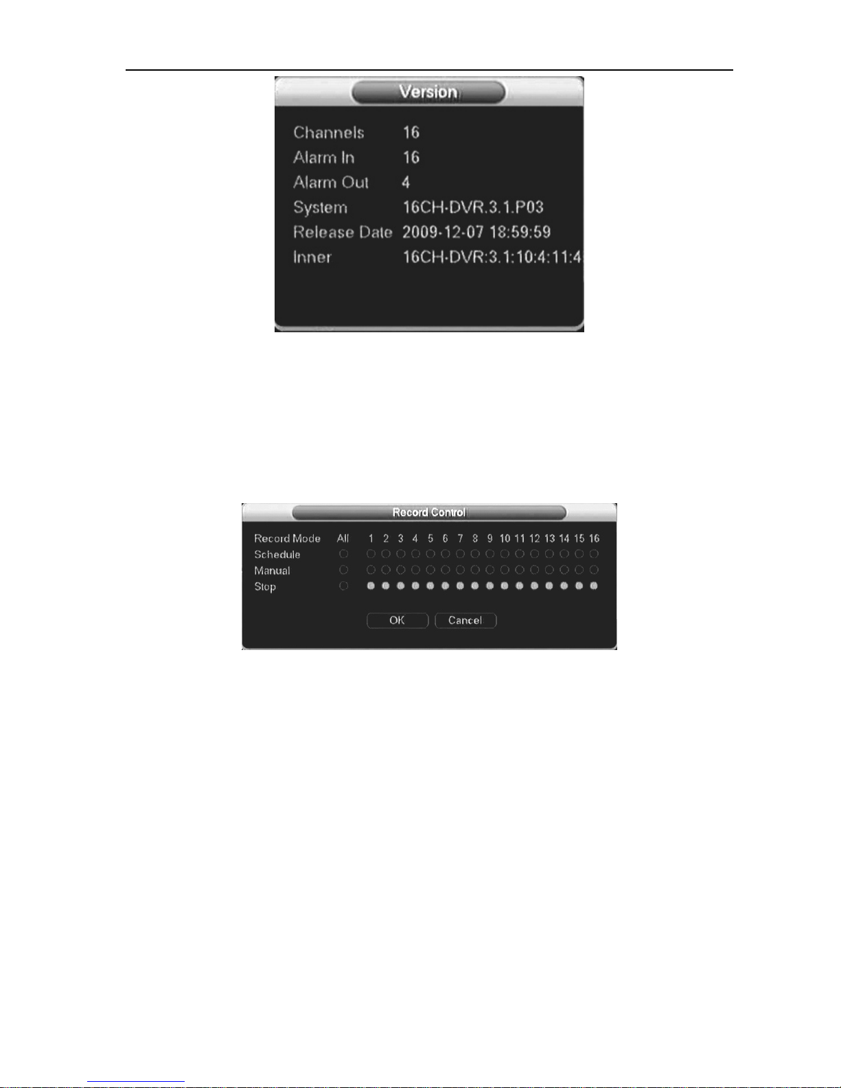
3.7.4 Version
Display system hardware’s feature, software version and issue date etc.
43
Digital Video Recorder User Manual
3.8 Control function
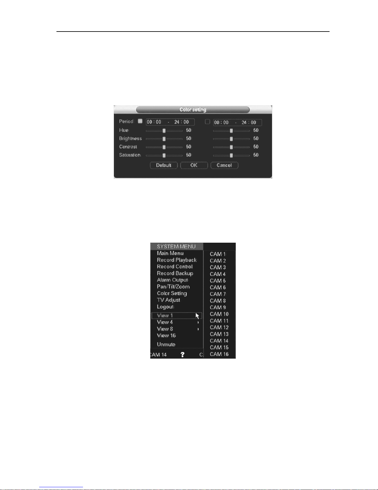
3.8.1 Record control
There are two ways for you to go to manual record menu.Right click mouse or in the main
menu, Advanced->Manual Record. In live viewing mode, click record button in the front panel or
record button in the remote control
There are three statuses: schedule/manual/stop. Highlight icon“○” to select corresponding channel.
1. Manual: the highest priority. After manual setup, all selected channels will begin ordinary
recording.
2. Schedule: channel records as you have set in recording setup (Main Menu->Setting->Schedule)
3. Stop: all channels stop recording.
Enable all channel recording: system enable all channel recording
Stop all channel recording: System stops all channel recording
Enable/disable record
Please check current channel status: “○” means it is not in recording status, “●” means it is in
recording status.
You can use mouse or direction key to highlight channel number.
Enable all channel recording
Highlight ○ below All, you can enable all channel recording.
All channel schedule record
Please highlight “ALL” after “Schedule”.
44

Digital Video Recorder User Manual
When system is in schedule recording, all channels will record as you have previously set (Main
menu->Setting->Schedule).
The corresponding indication light in front panel will turn on
All channel manual record
Please highlight “ALL” after “Manual.”.
When system is in manual recording, all scheduled set up you have set in will be null ((Main
menu->Setting->Schedule)).
You can see indication light in front panel turns on, system begins manual record now.
Stop all channel recording
Please highlight “ALL” after “Stop”.
System stops all channel recording no matter what mode you have set in the menu (Main
menu->Setting->Schedule)
3.8.2 PTZ control
Note: The protocols not supported will be displayed in grey color.
Here you can set the following items: Step, Speed, Zoom, Focus, Iris, Presets, Patrol, Pattern, Line
Scan, AGC, BLC, etc.
Hide PTZ menu by double click the menu title.
45

Digital Video Recorder User Manual
Click Pan/Tilt/Zoom, the interface is shown as below,
Speed: mainly to control direction. For example, step 8 is much faster than step 1. (Input the
number 1~8 by mouse click or front panel, 8 is the biggest)
Click icon zoom, focus, iris,
and to adjust zoom, focus and iris
Please click direction arrows to adjust PTZ position. There are total 8 direction arrows, up, down,
left, right, left-up, right-up, left-down, right-down respectively. (up, down, left, right only when using
front panel)
Shortcut
Function
key
function
Shortcut
key
Function
key
function
Name
Key
Zoom Near Far
Focus Near Far
Iris
46
close Open
Click the “set” button. The interface is shown as below. (shortcut key: video key “●”) . Here you can
set the following items: Preset, Tour, Pattern, and Border.
The function in figure 2 mainly according to protocols. If not support will be displayed as gray,
right click mouse or press ESC key on the front panel back to figure 1.
Patrol setup (Tour Setup)
Click patrol button. The interface is shown as below. Input preset number and add this preset to a
patrol (tour). For each patrol (tour), you can input max 80 presets.
Activate Patrol (tour)
Input patrol (tour) number in the No. blank and click patrol button

Digital Video Recorder User Manual
Pattern Setup
Click pattern button and then click “begin” button. The interface is shown as below. Then you can
modify zoom, focus, iris and direction.
Click “end” button. You can memorize all these operations as pattern 1.
Input mode value in the No. blank, and click pattern button.
Auto Scan Setup
Click border button. Use direction arrows to select camera left limit
Then please click left limit button
Repeat the above procedures to set right limit.
Activate Auto Scan
Click “Auto Scan” button, the system begins auto scan. Correspondingly, the auto scan button
becomes to stop button. Click stop button to terminate scan operation.
[Horizontal rotation] Enter the page as shows on Figure 5-65, click the button to turn the camera
rotate horizontally (compare with the present position).
47
Digital Video Recorder User Manual
Note: Preset, tour and pattern all need the value to be the control parameter. You can define it as you
require. You need to refer to your speed dome user’s manual for Aux definition. In some cases, it can
be used for special process.
3.8.3 Color Setting
According to time period, set hue, brightness, contrast, saturation and AGC, range is0~100,default
is 50
Note: A consecutive time period is necessary, furthermore, two time periods should not overlap
with each other and must equal to 24 hours totally. For instance, (08:00 ~ 8:00) or (08:00 ~
18:00 ;18:00 ~ 08:00). Otherwise the setting will not be saved.
3.8.4 Video display Split
View 1: you can select a channel to display
View 4: you can select 4-channel display as 1-4 or 5-8 channels
48

Digital Video Recorder User Manual
View 8: you can select 8-channel display
View16: you can select 16-channel display
49

Digital Video Recorder User Manual
3.9 Overview of Navigation and Controls
3.9.1 System Boot up
Connect the power supply, press switcher on backside panel, indicator light up and DVR boot up.
Default display mode is multiple picture output
System will start record video if set at schedule record mode, and the record channel indicator
light up.
3.9.2 Login
When the system boots up, Click Enter or left click mouse, you can see the login interface.
There are 2 default users: “admin” “guest”.
“admin” users have administrator right. The default password is “123456” for all 2 default users’
account. “guest” user only can review playback and backup.
Password protection: you can input password 5 times within 30 minutes, otherwise the account
will be locked. For your system security, please modify you password after first login.
You can use USB mouse, front panel, remote controller or keyboard to input. About input method:
Click
to switch between numeral, English character (small/capitalized) and Chinese
3.9.3 System Shutdown
Note: Power off system before change the HDD.
Method 1: Press the POWER button at the front over 3sec to stop the disc video recorder, then
shut the power off at the rear panel.
Method 2: System menu -> Shut down the system
Method 3: System menu -> Main menu ->Management tools -> Shut down the system.
3.9.4 Preview
Enter into “Preview” menu, you can setup date and time according to “General Setting”, or setup
the channel name according to “Output Mode”
50

Digital Video Recorder User Manual
1
The logo displayed on
the screen when
recording
The logo displayed on the screen
when motion detection
2
The logo displayed on
the screen when video
lost occur
The logo displayed on the screen
when camera masking occur
4
3
3.9.5 Auto Resume after Power Failure
The system can automatically backup video and resume previous working status after power
failure.
3.9.6 Replace Button Battery
Please make sure to use the same battery model if possible.
We recommend replace battery regularly (such as one-year) to guarantee system time
accuracy
51

Digital Video Recorder User Manual
Chapter4 WEB CLIENT OPERATION
4.1 Router forwarding
1) Set the host IP
Set the host IP in“Local setting”,please refer to the chapter “Net set”.
2) Port forwarding
Sign router interface, mapping port. For example, the host IP address set to 192.168.2.101, port 80, while
the router model CISCO WRT54G2 V1, the default IP route to 192.168.2.1, then enter in the browser
address bar, the IP address, then enter a user name password (router user name password can view the
router's manual) into the router interface. Click "Applications&Gaming" enter the following interface:
Set as above, then click ”save settings” to save the settings.
3)DDNS Domain Name
For example, DYNDNS software here, first of all to the DYNDNS site (www.dyndns.com) apply for
an account and domain name.
Dyndns login in two ways: First, the host to set DDNS, the second is the router (provided that the route to
support domain name resolution function) set. the host to set DDNS,please refer to "DDNS Settings"
relevant chapters. To do DDNS in the router, click the “Setup” in the router main menu ,then click "DDNS"
option, enter the following interface:
52

Digital Video Recorder User Manual
Input the Dyndns user name ,password and Host name, that is finish the settings
4)Remote login
Input the Domain name in IE browser. You also can input the domain name in software to
remote login the host.
4.2 IE Browser Setup
Please make sure your PC installed Microsoft Internet Explorer 6.0, and DirectX 9.0 or higher
version.,
Note: Please turn off the Firewall and Antivirus Software if necessary. When log in the
DVR first time, if all the functions run properly, in this case you could set the Security as
default level.
a) Open Internet Explorer and press“tool”->“Internet options”to bob up the following
dialog box:
b)
53

Digital Video Recorder User Manual
c) Press“Trusted sites”and “sites” in red box as follow to bob up the “trusted sites” dialog box:
d) Input the DVR IP, press“add” and “OK” to quit this dialog box.
54

Digital Video Recorder User Manual
e) After above setting, press“default level” to set the “security level” into “low” and then press
“Apply”.
-+
55

Digital Video Recorder User Manual
f) Or you can set the custom level: press “custom level”and enable all clauses under the “ActiveX
controls and plug-in” options.
g) In IE “Privacy” label, please cancel the “√” before the “Pop-up block”and then press“Apply”。
56
Digital Video Recorder User Manual
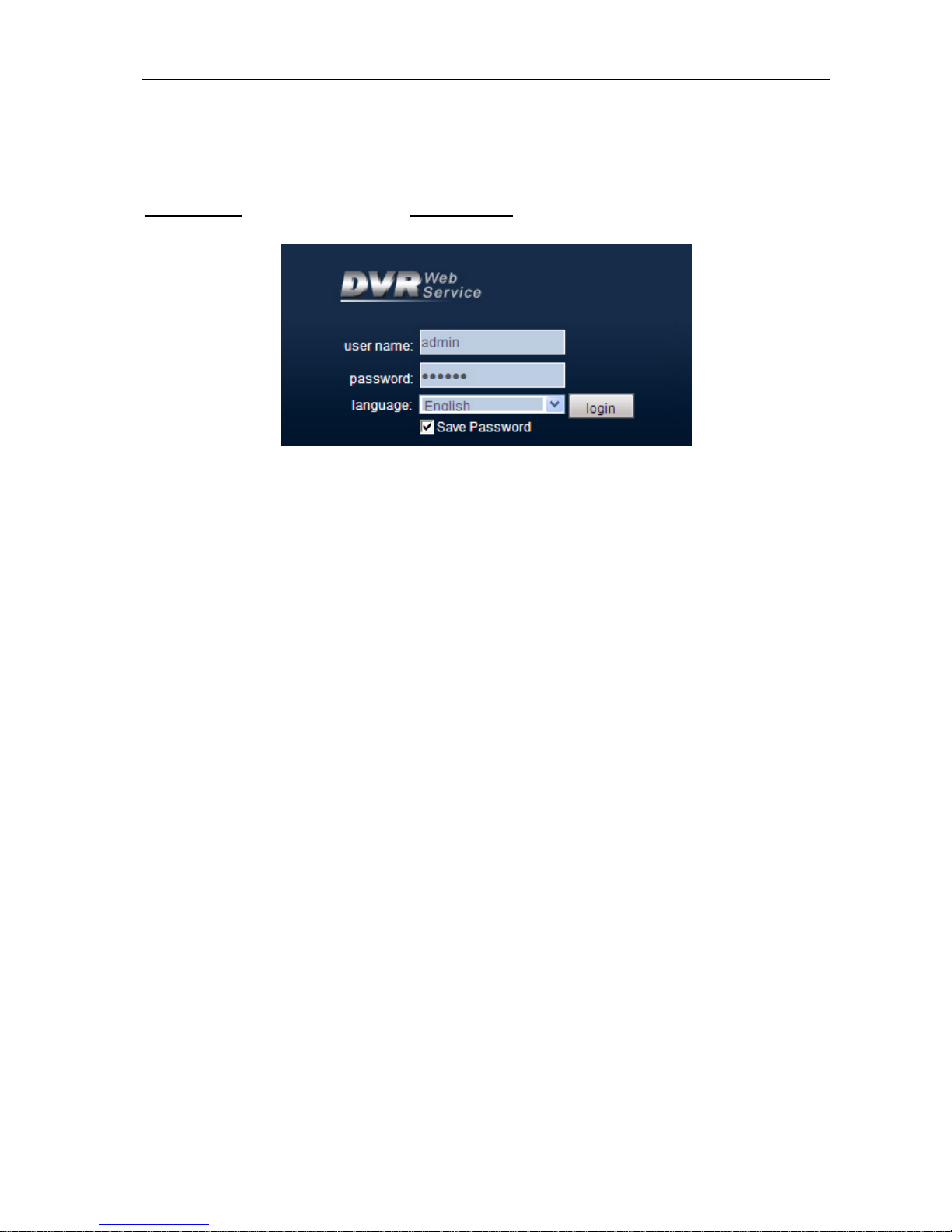
4.3 Login
This chapter mainly introduces DVR’s Web client-end operation.
Open IE and input DVR address in the address column. For example, if your DVR IP is
192.168.1.108, then please input http:// 192.168.1.108 in IE address column...
System pops up warning information to ask you whether install webrec.cab control or not.
Please click yes button Please input your user name and password.
Default factory name is admin and password is 123456
Note: For security reasons, please modify your password after you first login
Please check the following items:
1.Network connection is right
2.DVR and PC network setup is right. IP address, Subnet Mask, Gateway, Please refer to
network setup(main menu->setting->network)
3, Use order ping ***.***.***.***(* DVR IP address) to check connection is OK or not. TTL
value 64
4. Web OCX will be downloading and install automatically, when update a new OCX, old
version OCX should be uninstalled
57

Digital Video Recorder User Manual
58
 Loading...