

Page 1

30' x 40' UltraMax
Assembly Instructions
™
Peak Canopy
DESCRIPTION MODEL #
™
30' x 40' UltraMax
Please read instructions COMPLETELY before assembly. This shelter MUST be securely anchored.
THIS IS A TEMPORARY STRUCTURE AND NOT RECOMMENDED AS A PERMANENT STRUCTURE.
Before you start: 2+ individual recommended for assembly, approximate time 2.5 hr.
14-leg Peak Canopy 27773
RECOMMENDED TOOLS
150 Callender Road
Watertown, CT 06795
www.shelterlogic.com
7/23/10
1-800-524-9970
Canada:
1-800-559-6175
05-27773-0BPage 1
Page 2
ATTENTION:
This shelter product is manufactured with quality materials. It is designed to t the ShelterLogic
ShelterLogic
Please anchor this ShelterLogic
®
, LLC Shelters offer storage and protection from damage caused by sun, light rain, tree sap and animal - bird excrement.
®
, LLC structure properly. See manual for more anchoring details. Proper anchoring, keeping cover
tight and free of snow and debris is the responsibility of the consumer. This shelter is not recommended for severe weather conditions.
Please read and understand the installation detail, warnings and cautions prior to beginning installation. If you have any questions call
the customer service number listed below. Please refer to the warranty card inside this package.
®
, LLC custom fabric cover included.
DANGER:
Prior to installation, consult with all local municipal codes regarding installation of temporary shelters.
Choose the location of your shelter carefully. DANGER: Keep away from electrical wires. Check for
overhead utility lines, tree branches or other structures. Check for underground pipes or wires before
you dig. DO NOT install near roof lines or other structures that could shed debris onto your shelter.
DO NOT hang objects from the roof or support cables.
WARNING:
Risk of re. DO NOT smoke or use open ame devices (including grills, re pits, deep fryers, smokers or
lanterns) in or around the shelter. DO NOT store ammable liquids (gasoline, kerosene, propane, etc.) in
or around your shelter. Do not expose top or sides of the shelter to open re or other ame source.
CAUTION:
Use CAUTION when erecting the frame. Use safety goggles during installation. Secure and bolt together
overhead poles during assembly. Beware of pole ends.
PROPER ANCHORING AND INSTALLATION OF FRAME:
PROPER ANCHORING OF THE FRAME IS THE RESPONSIBILITY OF THE CONSUMER.
ShelterLogic
securely has the potential to y away causing damage, and is not covered under the warranty. Periodically check the anchors to ensure
stability of shelter. ShelterLogic
quickly removed and stored prior to severe weather conditions. If strong winds or severe weather is forecast in your area, we recommend removal of cover.
®
, LLC
is not responsible for damage to the unit or the contents from acts of nature. Any shelter that is not anchored
®
, LLC cannot be responsible for any shelter that blows away. NOTE: Your shelter’s cover can be
REPLACEMENT PARTS, ASSEMBLY, SPECIAL ORDERS:
Genuine ShelterLogic
application, replacement covers, wall and enclosure kits, vent and light kits, frame parts, zippered doors and other accessories. All
items are shipped factory direct to your door.
QUESTIONS - CLAIMS - SPECIAL ORDERS? CALL OUR CUSTOMER SERVICE HOTLINE:
U.S. CUSTOMER SERVICE: 1-800-524-9970 INTERNATIONAL CUSTOMER SERVICE: 001-860-945-6442 CANADA CUSTOMER SERVICE: 1-800-559-6175
HOURS OF OPERATION: MON-FRI 8:30AM-8:00PM EST, SAT-SUN 8:30AM-5:00PM EST.
®
, LLC replacement parts and accessories are available from the factory, including anchoring kits for nearly any
CARE AND CLEANING:
A tight cover ensures longer life and performance. Always maintain a tight cover. Loose fabric can accelerate deterioration of cover fabric. Immediately remove any accumulated debris from the roof structure with a
broom, mop or other soft-sided instrument. Use extreme caution when removing debris from cover- always
remove from outside the structure. DO NOT use hard-edged tools or instruments like rakes or shovels to
remove debris. This could result in punctures to the cover. DO NOT use bleach or harsh abrasive products to
clean the fabric cover. Cover is easily cleaned with mild soap and water.
WARRANTY:
This shelter carries a full limited warranty against defects in workmanship. ShelterLogic
properly used and installed, the product and all associated parts, are free from manufacturer’s defects for a period of:
1 YEAR FOR COVER FABRIC, END PANELS AND FRAMEWORK
Warranty period is determined by date of shipment from ShelterLogic®, LLC for factory direct purchases or date of purchase from an authorized
reseller, (please save a copy of your purchase receipt). If this product or any associated parts are found to be defective or missing at the time of receipt,
ShelterLogic
shall be covered for the remainder of the Original Limited Warranty Period. All shipping costs will be the responsibility of the customer. Parts and replacements will be sent C.O.D. You must save the original packaging materials for shipment back. If you purchased from a local dealer, all claims must have a
copy of original receipt. After purchase, please ll out and return warranty card for product registration. Please see warranty card for more details.
®
, LLC will repair or replace, at it’s option, the defective parts at no charge to the original purchaser. Replacement parts or repaired parts
®
, LLC warrants to the Original Purchaser that if
Covered by U.S. Patents and patents pending: 6,871,614; 6,994,099; 7,296,584; D 430,306; D 415,571; D 414,564; D 409,310; D 415,572
05-27773-0BPage 2
Page 3

30'x40' ULTRA MAX PEAK CANOPY Model #27773
Part Part #QuantityDescription
Support Tube 72
Rafter Tube 72
Oblique Tube 72
Rafter Extension Tube 42
Cross Rail 77
Pocket Pipe 77
(Top Bend, Shallow Bend)
3-Way Frame Connectors
3
in. / 183,9 cm 4
/
8
3
in. / 183,9 cm
/
8
3
in. / 183,9 cm
/
8
3
in. / 107,1 cm
/
16
1
in. / 195,9 cm
/
8
3
in. / 196,5 cm
/
8
24
14
14
18
12
2
800216
800095
800096
800090
800098
800230
800091
4-Way Frame Connectors
(Side Bend, Sharp Bend)
3-Way Frame Connectors
4-Way Frame Connectors
Wind Brace (Swedged Ends)
Wind Brace (Flat Ends)
Cover
4-Way Cover Rail Clamp
3-Way Cover Rail Clamp
Heavy-Duty Stake Anchors
Ropes
Base Feet
5
4
10
7
7
1
20
8
18 800140
18 10437
14
800093
800092
800094
800104
800103
800231
800221
800220
800105
5
/
5
/
5
/
5
/
Spike Anchor
Ratchet
White Rope
Rope Bead
"S" Hook
1
x 2
16
x 2 in. / 8 x 50,8 mm Round Head Bolts
16
x 3 in. / 8 x 76,2 mm Round Head Bolts
16
in. / 8 mm Nuts
16
in. / 8 x 57,2 mm Bolts
/
4
24
43
84
151
56
4
2
4
4
11130
800217
800218
00690
10431
10040
800233
10465
800225
05-27773-0BPage 3
Page 4

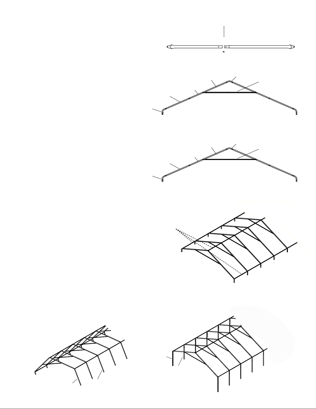
Frame Basic Overview
05-27773-0BPage 4
Page 5
800216
800095
Basic Frame Assembly
Step 1
Assemble the wind brace set as shown in Figure 1.
Step 2
See Figure 2A.
Fit together the end rib using the following parts
(1) #800091 3-Way Top Connectors
(2) #800096 Rafter Poles
(2) #800090 Extend tube
(2) #800095 Common Tubes
(2) #800092 3-Way Side Connectors
(1) Wind Brace set
Fig 2B:
Fit together the middle rib using the following parts
(1) #800093 4-Way Top Connectors
(2) #800096 Rafter Poles
(2) #800090 Extend Tube
(2) #800095 Common Tubes
(2) #800094 4-Way Side Connectors
(1) Wind Brace set
5
Using (8) #800218 (
x 3 in. Bolts) and (8) Nuts
/
16
securely fasten these tubes. Lay these ribs on the
ground at the rear of your shelters designated location.
800092
800094
Fig. 1
Fig. 2A:
2 End Ribs
800090
800095
Fig. 2B:
Middle Ribs
800090
800095
#800217
#800103
800096
#00690
800091
Use #800218 Bolt (
800096
800093
Use #800218 Bolt (
#800104
Wind brace
5
x 3 in.)
/
16
Wind brace
5
x 3 in.)
/
16
NOTE: Be sure that all of the heads of the bolts are
facing toward the outside of the rib.
Repeat step 2A/2B for all the other ribs.
800098
Fig. 3
Step 3
Using #800098 Cross Rails, #800217
5
(
x 2 in. Bolts) and Nuts to connect
/
16
these ribs. See Figure 3
Step 4
Assemble (2) #800216 Corner Support Tubes and (4) # 800095 middle support tube as shown in Fig. 4A and
set aside. Assemble other side Support Tubes as shown in Fig. 4B and connect the middle support tubes with
#800218 (
Note: #800218 Bolts are required for middle support tube connections. Bolts are NOT inserted to the
corner legs (#800216) at this step.
5
/
16
Fig. 4A
x 3 in. Bolts) and nuts. Repeat this step at opposite side.
Fig. 4B
800216
800095
05-27773-0BPage 5
Page 6

Step 5
Depending on the model you have purchased, your
base feet will either t onto the outside of the leg poles,
or slide inside the leg poles.
After installing Base Feet Plates onto bottom of Leg
Poles, line up the predrilled hole in the leg with the
predrilled hole in the base foot. (Fig. 5A)
Insert
other side, secure with nuts. (Fig. 5B)
Note: Don't insert the bolt to the corner legs at this
step.
Place 4 anchors as shown in Fig. 5B into each hole of
the base feet until the head of the anchor touches the
base feet.
5
x 3 in. bolts all the way through leg and foot to
/
16
Fig. 5A
Fig. 5B
Step 6
Tie a loop into the end of the
rope.
Feed the loop over the
top of the rafter pole and feed
the other end of the rope through
the loop and run the rope down
the leg at least 12 inches and wrap
the rope around the leg and
feed the loose end over the
rope (Fig.6A).
Take the loose end of the robe
and secure it to the auger anchor already secured in the ground
(Fig.6B).Repeat these steps for the
remaining legs on the canopy.
Fig. 6
Fig. 6A
rope
Fig. 6B
05-27773-0BPage 6
Page 7

Step 7
Position the cover on the side of the frame with the side with the grommets parallel to the frame and facing down. Go to
the opposite side of the frame and throw at least three ropes over the frame (evenly spaced along the length of the frame).
Tie the ropes to the grommets on the cover and use the rope to pull the cover over the frame (the more people and ropes
you have to pull the cover over the easier it is to do). Position the cover so that the valance is even front to back and side
to side.
Slide the pocket pipes into the cover pockets between the cutouts. Attach the pocket pipes to the frame using the 3 &
4 way clamps (800220 & 800221) and the 5/16 X 2 1/4 #11130 bolts and nuts. Check that the pocket pipes are evenly
spaced on both sides of the top pipe. Slide the pocket pipe down the length of the rafters to tighten the top section of the
cover. When the cover is pulled tight secure the bolts and nuts in the sliding clamps to hold them in place.
800220
1113 0
800230
00690
End Rib
Fig. 7A
Slide the rope through the grommets and around
the side extention tubes at both sides shown
in Fig.7C. Insert the 'S' hook to the
corner leg tube, then 'twist' the leg to tighten the rope
(Fig.7D).
After tightening the rope, secure the (4) corner leg tubes
#800216 to the corner connectors and feet plates with
#800218 (5/16 x 3 in. Bolts) and nuts.
Fig. 7C
800230
00690
Middle
Rib
800221
1113 0
800230
00690
Fig. 7B
Fig. 7D
Step 8
Use the (4) Ratchets as shown in Fig.8A.
Adjust the cover so there is equal overhang
on the front and rear. With the webbing and
ratchets pull the cover snug but not tight.
When all of the half clamps and rope are
secured tight nish tightening the (4) Ratchets
to make nal adjustment to the cover.
Fig. 8A
Fig. 8B
05-27773-0BPage 7
Page 8

9,1 x 12,2 m Tente UltraMax
™
LES TRADUCTIONS FRANÇAISES D'INSTRUCTION D'ASSEMBLAGE
DESCRIPTION MODÈLE Nº
9,1 x 12,2 m Tente UltraMax™ 27773
OUTILS RECOMMANDÉS
Lire TOUTES les instructions avant de monter. Cet abri DOIT être bien ancré.
Ceci est une structure temporaire, il n'est pas recommandé d'en faire une structure permanente.
Avant de commencer: Il faut 2+ personnes ou plus pour le montage qui prend environ 2.5 heures.
150 Callender Road
Watertown, CT 06795
www.shelterlogic.com
7/23/10
1-800-524-9970
Canada:
1-800-559-6175
Page 8 05-27773-0B
Page 9

ATTENTION:
Ce produit Shelter est conçu avec des matériaux de la plus haute qualité. Il est conçu pour être utilisé avec la toile fabriquée par Shelterlogic. ShelterLogic
les excréments animaliers et une légère tomber de neige. S’il vous plait ancrez la structure ShelterLogic
recte. Un ancrage correcte, garder la toile bien tendue et sans accumulation de neige et sans débris est la responsabilité du consommateur. Prenez bien soin de lire et de comprendre les détails de l’installation, les remarques et avertissements avant l’installation nale
du produit. Si vous avez des questions appeler le service clientèle afcher sur la première page de votre manuel d’installation. Aussi
référencez-vous à la carte de garantie fournie avec votre achat.
®
, LLC offre un abri et une protection contre les faits malfaisants du soleil, une pluie légère, la sève des arbres,
®
, LLC d’une manière cor-
DANGER:
Choisissez avec soin l’emplacement de l’abri. Danger: Installez à distance de ls électrique. Faites
attention aux lignes à haute tension, branches d’arbre et autre structure. NE PAS installer près de
toits, ou tout autres structures des quels de la neige, glace, ou eau excessive pourrait tomber sur
l’abri. Ne pas pendre d’objet sur labri.
ATTENTION:
Risque de feu. NE PAS fumer ou utiliser des outils à amme ouverte (barbecue, friteuse, fumoirs ou
lanternes) dans ou aux alentours de l’abri. NE PAS stocker de liquide inammable (gazoline, kérosène,
propane, etc.) dans ou aux alentour de votre abri. N’exposer pas le toit ou les cotes à une amme ouverte ou toute autre source de feu.
AVERTISSEMENT:
Soyez très prudent pendant la construction de la charpente. Utilisez des lunettes de protection pendant la durée de l’installation. Sécurisez et boulonnez ensemble tout les tubes de la toiture pendant l’assemblage. Attention au bout des tuyaux.
MISE EN GARDE:
L’ANCRAGE CORRECT DE LA PORTE AUTOMATIQUE EST LA RESPONSABILITÉ DU CONSOMMATEUR.
ShelterLogic
et de façon sécuriser a le potentiel d’être endommager, et ne sera pas couvert sous la garantie. Vérifier les ancres et la charpente de
façon périodique pour s’assurer de la stabilité. REMARQUE: La couverture de votre abri peut être rapidement enlevé et stocker avant
des conditions météorologiques sévères. Si des vents forts ou des conditions sévères sont annoncées, nous recommandons d’enlever
la couverture.
®
, LLC
n’est pas responsable pour tout dommage à l’unité. Toute porte automatique qui n’est pas ancrée correctement
PIÈCES DE REMPLACEMENT. ASSEMBLAGE. COMMANDES SPÉCIALES:
Des pièces de rechange ShelterLogic
de rechange, panneau et kit d’enclosure, kit de lumière et de ventilation, tube de charpente, portes à glissières et autres accessoires.
Tous sont envoyés direct de l’usine à votre domicile.
QUESTIONS – RÉCLAMATIONS – COMMANDES SPÉCIALES? APPELER NOTRE SERVICE CLIENTÈLE:
SERVICE CLIENTÈLE US: 1-800-524-9970 SERVICE CLIENTÈLE INTERNATIONAL: 001-860-945-6442 SERVICE CLIENTÈLE CANADIEN: 1-800-559-6175
HEURES D’OPÉRATIONS: LUNDI – VENDREDI: 8:30AM – 8:00PM EST, SAMEDI – DIMANCHE: 8:30AM – 5:00PM EST.
®
, LLC et accessoires sont disponible direct de l’usine, inclus sont des kits d’ancrages, couverture
ENTRETIEN ET NETTOYAGE:
Une couverture bien tendue assurera une vie plus longue et de meilleur performances. Toujours maintenir la
couverture bien tendue. Une couverture mal tendue peut accélérer la détérioration de la couverture. Enlever du
toit toute accumulation de neige ou de glace immédiatement avec l’aide d’un balai, d’un balai serpillère ou autre
instrument à bord doux. Garder le raille propre et sans débris. NE PAS utiliser d’eau de javèle ou autre produits
nettoyant abrasive pour nettoyer la couverture. Le panneau de porte peut être facilement nettoyé avec de l’eau
et du savon. NE PAS utiliser des outils a bord coupant, ou des instruments comme râteau ou pelle pour enlever
la neige. Cela pourrait trouer la couverture. N’utiliser pas d’eau sous haute pression.
GARANTIE:
Comprend une garantie limitée contre les défauts de fabrication. ShelterLogic
de façon correcte, le produit et toutes pièces associer, seront sans défauts de fabrication pour une période de:
1 AN POUR LA COUVERTURE, LES PANNEAUX AVANT ET ARRIERE ET LA CHARPENTE.
La période de garantie est déterminer par la date d’envoie de l’usine de ShelterLogic®, LLC, pour les commandes directes, ou par la date d’achat
d’un distributeur autoriser à la vente. (S’il vous plait conserver la copie de votre reçu d’achat). Si ce produit ou toutes pièces associées sont défectu-
euses ou manquantes au moment de la réception, ShelterLogic®, LLC réparera ou remplacera, à sa discrétion, les pièces défectueuses sans frais
au consommateur. Les pièces de remplacement ou pièces réparées seront couvertes pour le reste de la garantie original limitée. Tout frais de port sera
la responsabilité du consommateur. Pièces et remplacements seront envoyés en COD. Vous devez conserver l’emballage original pour les renvoies. Si
vous acheter dans un distributeur local, toutes réclamations doivent être accompagné du reçu d’achat. Après l’achat, remplissez et renvoyez la carte de
garantie pour enregistrer le produit. Voir carte de garantie pour plus de détails.
®
, LLC garantie aux propriétaires que si utiliser et installer
Couvert par un ou plus des brevets ou brevets en attente: 6,871,614; 6,994,099; 7,296,584; D 430,306; D 415,571; D 414,564; D 409,310; D 415,572
Page 9 05-27773-0B
Page 10

Tente UltraMax™ de 9,1 x 12,2 m Modèle No #27773
Partie Partie #
Tube de support 72
Poteau de Comble 72
Tube Oblique 72
Tube d’extension 42
Rails transversaux 77
Pipe de Poche 77
(Tube courbé supérieur, courbe légère)
Connecteur à 3 voix
Connecteur à 4 voix
(tube courbé, très courbé)
Connecteur à 3 voix
Connecteur à 4 voix
Support contre vent (bout rafner)
Support contre vent (bout plat)
3
po. / 183,9 cm 4
/
8
3
po. / 183,9 cm
/
8
3
po. / 183,9 cm
/
8
3
po. / 107,1 cm
/
16
1
po. / 195,9 cm
/
8
3
po. / 196,5 cm
/
8
QuantitéDescription:
800216
24
14
14
18
12
2
5
4
10
7
7
800095
800096
800090
800098
800230
800091
800093
800092
800094
800104
800103
Couverture
Etau à 4 voix
Etau à 3 voix
Heavy-Duty Stake Anchors
Ropes
Pieds
5
/
5
/
16
5
/
16
5
/
Ancrer Sardines
1
x 2
16
x 2 po. / 8 x 50,8 mm Boulons à tête arrondis
x 3 po. / 8 x 76,2 mm Boulons à tête arrondis
po. / 8 mm Ecrous
16
po. / 8 x 57,2 mm Boulons
/
4
1
20
8
18 800140
18 10437
14
24
43
84
151
56
800231
800221
800220
800105
11130
800217
800218
00690
10431
Cliquet
Cordes - Blanc
Corde Ficelle
Boule et crochet en « s »
Page 10 05-27773-0B
4
2
4
4
10040
800233
10465
800225
Page 11

Charpente de base vue d'ensemble
Page 11 05-27773-0B
Page 12

800216
800095
Assemblement de la Charpente
Etape 1
Assemblez le croisillon de vent suivant les indications
de la gure 1.
Etape 2
Voyez Figure 2A.
Assembler l’ossature de bout en utilisant les pièces
suivantes:
1 – 800091 – Connecteur à 3 voix supérieur
2 – 800096 – Tube de comble
2 – 800090 – Tubes d’extension
2 – 800095 – Tube commun
2 – 800092 – connecteurs à 3 voix des coté
1 – Support contre vent
Etape 2B
Assembler les ossatures du milieu en utilisant les pièces
suivantes :
1 – 800093 – Connecteurs à 4 voix supérieur
2 – 800096 - Tube de comble
2 – 800090 – Tube d’extension
2 – 800095 – Tube commun
2 – 800094 – Connecteur à 4 voix de coté
1 – Support contre vent utilisant
800218 (boulons de 8 x 76,2 mm) et 8 écrous
Etaler les structures près de l’emplacement nal de la
tente.
REMARQUE: Assurez-vous que toutes les têtes de
boulon soit installer vers l’extérieur de la
charpente.
Répéter les étapes 2A/2B pour toutes les autres
ossatures.
800092
800094
Fig. 1
#800103
Fig. 2A:
2 nervures d'extrémité
800096
800090
800095
Utilisez #800218 Boulon (8 x 76,2 mm)
Fig. 2B:
milieu nervures
800090
800095
800098
800096
Utilisez #800218 Boulon (8 x 76,2 mm)
#800217
#00690
800091
800093
#800104
support contre vent
support contre vent
Fig. 3
Etape 3
Utiliser les tubes horizontaux 800097 et boulons
800217 (8 x 50,8 mm) et écrous pour connecter les
ossatures. Voyez Figure 3
Etape 4
Assembler les 2 tubes de support au coins 8000216 et les 4 tube de support du milieu 800095 comme montré dans la
g. 4A et mettez de coté. Assembler les tubes de support de l’autre coté comme montré dans la Fig.4B, et connecter les
tubes de support de milieu avec les boulons 800218 (8 x 76,2 mm) et écrous. Répéter cela pour l'autre coté.
REMARQUE: Les boulons 800218 sont requis pour les connections de tube de support. Les boulons ne doivent
pas être insérer dans les jambes des coins (800216) pour cette étape.
Fig. 4B
Fig. 4A
800216
800095
Page 12 05-27773-0B
Page 13

Etape 5
D’après le modèle que vous avez acheté, les pieds
se glisseront à l’intérieur des jambes, ou autour des
jambes.
Apres les avoirs installer sur les jambes, assurer
vous de bien aligner les trous (Fig. 5A) et installer les
boulons de
8 x 76,2 mm au travers du pied et de la jambes, et
sécuriser avec l’écrou. (Fig. 5B)
REMARQUE: Ne pas installer les boulons dans
pour cette étape. Choisissez la location pour
placer les 4 ancres comme montré dans
l’illustration dans chaque pieds, jusqu’à ce que
les bouts rond des ancres touches les pieds.
Fig. 5A
Fig. 5B
Etape 6
Faites un nœud en boucle au
bout de la corde.
Passer la corde par-dessus le
tube de comble et passer l’autre
bout de la corde dans la boucle,
faite passer la corde autour de
la jambe à au moins 12 po. et
passer le bout par-dessus la
corde. (Fig.6A)
Prenez le bout de la corde, et
attacher le à l’ancre foreuse
déjà installer dans le sol
(Fig.6B). Répéter cela pour le
reste des jambes de la tente.
Fig. 6
Fig. 6A
corde
Fig. 6B
Page 13 05-27773-0B
Page 14

Etape 7
Poser la toile à coté de la charpente avec le coté qui a les œillets parallèle à la charpente, vers le sol.
Allez de l’autre coté de la charpente, et lancer au moins 3 corde par-dessus la charpente (bien espacé de façon égale le
long de la charpente). Attacher les cordes aux œillets sur la toile, et tirer la toile par-dessus la charpente (le plus de personnes et le plus de cordes vous avez rendrons cela plus facile). Placer la toile de façon à ce que les bords soient égaux
à l’avant et l’arrière, et de chaque coté.
Glisser les tube de couverture dans les poches qui sont sur la toile, et attacher les tubes en utilisant les étaux à 3 et 4 voix
(800220 et 800221) et les boulons 11130 de 8 x 57,2 mm. Assurez-vous que les tubes de couvertures soient bien espacés sur chaque coté du tube du haut. Glisser les tubes de couverture le long des tubes de comble pour tendre la section
supérieur de la toile. Quand celle-ci et bien tendue, serrer les boulons pour bien tenir les étaux en place.
800220
1113 0
800230
00690
Ossature du Bout
Fig. 7A
Passer la corde dans les œillets et autour des tubes
d’extension sur chaque coté comme montré dans les
g.7Cm 7D, et g. 7D et 7E. Insérer les crochets en S
dans les tubes des coins, et tourner la jambe pour serer
la corde.
Après avoir tendue la corde, sécuriser les 4 jambes de
coin 800216 au connecteurs de coin et aux pieds avec
les boulons 800218 (8 x 76,2 mm) et écrous
Fig. 7C
800230
00690
Ossature
du Milieu
800221
1113 0
800230
00690
Fig. 7B
Fig. 7D
Etape 8
Utiliser les 4 cliquets comme montré dans la
g.8A.
Ajuster la toile de façon à ce que les bords
tombent de façon égale à l’avant et l’arrière.
Avec les sangles et les cliquets, tendre la toile
mais pas trop serrer. Une fois que tous les étaux
sont bien serrer et sécuriser, alors bien tendre la
toile avec les 4 cliquet pour faire les ajustements
nals sur la toile.
Fig. 8A
Page 14 05-27773-0B
Fig. 8B
 Loading...