

Page 1
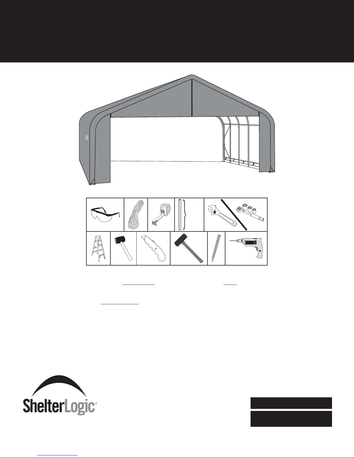
26'W x 16'H Peak Shelter
Assembly Manual
+
/
-
18"
45 cm
Please read instructions COMPLETELY before assembly. This shelter MUST be securely anchored.
THIS IS A TEMPORARY STRUCTURE AND NOT RECOMMENDED AS A PERMANENT STRUCTURE.
Before you start: 5 or more individuals recommended for assembly.
Assembly time is dependent upon the length of your building.
Allow approximately 15 minutes for every foot in building length.
150 Callender Road
Watertown, CT 06795
www.shelterlogic.com
1/15/13
1-800-524-9970
Canada:
1-800-559-6175
05_10A163_B1Page 1
Page 2
ATTENTION:
This shelter product is manufactured with quality materials. It is designed to t the ShelterLogic
ShelterLogic
and light snow. Please anchor this ShelterLogic
®
Corp. Shelters offer storage and protection from damage caused by sun, light rain, tree sap, animal - bird excrement
®
Corp. structure properly. See manual for more anchoring details. Proper anchoring,
keeping cover tight and free of snow and debris is the responsibility of the consumer. Please read and understand the installation detail,
warnings and cautions prior to beginning installation. If you have any questions call the customer service number listed below. Please
refer to the warranty card inside this package.
®
Corp. custom fabric cover included.
DANGER:
Prior to installation, consult with all local municipal codes regarding installation of temporary shelters.
Choose the location of your shelter carefully. DANGER: Keep away from electrical wires. Check for
overhead utility lines, tree branches or other structures. Check for underground pipes or wires before
you dig. DO NOT install near roof lines or other structures that could shed snow, ice or excessive run
off onto your shelter. DO NOT hang objects from the roof or support cables.
WARNING:
Risk of re. DO NOT smoke or use open ame devices (including grills, re pits, deep fryers, smokers or
lanterns) in or around the shelter. DO NOT store ammable liquids (gasoline, kerosene, propane, etc.) in
or around your shelter. Do not expose top or sides of the shelter to open re or other ame source.
CAUTION:
Use CAUTION when erecting the frame. Use safety goggles during installation. Secure and bolt together
overhead poles during assembly. Beware of pole ends.
PROPER ANCHORING AND INSTALLATION OF FRAME:
PROPER ANCHORING OF THE FRAME IS THE RESPONSIBILITY OF THE CONSUMER.
ShelterLogic
securely has the potential to y away causing damage, and is not covered under the warranty. Periodically check the anchors to ensure
stability of shelter. ShelterLogic
quickly removed and stored prior to severe weather conditions. If strong winds or severe weather is forecast in your area, we
recommend removal of cover.
®
Corp.
is not responsible for damage to the unit or the contents from acts of nature. Any shelter that is not anchored
®
Corp. cannot be responsible for any shelter that blows away. NOTE: Your shelter’s cover can be
REPLACEMENT PARTS, ASSEMBLY, SPECIAL ORDERS:
Genuine ShelterLogic
application, replacement covers, wall and enclosure kits, vent and light kits, frame parts, zippered doors and other accessories. All
items are shipped factory direct to your door.
U.S. CUSTOMER SERVICE: 1-800-524-9970 INTERNATIONAL CUSTOMER SERVICE: 001-860-945-6442 CANADA CUSTOMER SERVICE: 1-800-559-6175
®
Corp. replacement parts and accessories are available from the factory, including anchoring kits for nearly any
QUESTIONS - CLAIMS - SPECIAL ORDERS? CALL OUR CUSTOMER SERVICE HOTLINE:
HOURS OF OPERATION: MON-FRI 8:30AM-8:00PM EST, SAT-SUN 8:30AM-5:00PM EST.
CARE AND CLEANING:
A tight cover ensures longer life and performance. Always maintain a tight cover. Loose fabric can accelerate
deterioration of cover fabric. Immediately remove any accumulated snow or ice from the roof structure with a
broom, mop or other soft-sided instrument. Use extreme caution when removing snow from cover- always
remove from outside the structure. DO NOT use hard-edged tools or instruments like rakes or shovels to
remove snow. This could result in punctures to the cover. DO NOT use bleach or harsh abrasive products to
clean the fabric cover. Cover is easily cleaned with mild soap and water.
WARRANTY:
This shelter carries a full limited warranty against defects in workmanship. ShelterLogic
if properly used and installed, the product and all associated parts, are free from manufacturer’s defects for a period of:
1 YEAR FOR COVER FABRIC, END PANELS AND FRAMEWORK.
Warranty period is determined by date of shipment from ShelterLogic® Corp. for factory direct purchases or date of purchase from an authorized
reseller, (please save a copy of your purchase receipt). If this product or any associated parts are found to be defective or missing at the time of receipt,
ShelterLogic® Corp. will repair or replace, at it’s option, the defective parts at no charge to the original purchaser. Replacement parts or repaired
parts shall be covered for the remainder of the Original Limited Warranty Period. All shipping costs will be the responsibility of the customer. Parts and
replacements will be sent C.O.D. You must save the original packaging materials for shipment back. If you purchased from a local dealer, all claims
must have a copy of original receipt. After purchase, please ll out and return warranty card for product registration. Please see warranty card for more
details.
®
Corp. warrants to the Original Purchaser that
Covered by U.S. Patents and patents pending: 6,871,614; 6,994,099; 7,296,584; D 430,306; D 415,571; D 414,564; D 409,310; D 415,572
090111
05_10A163_B1Page 2
Page 3
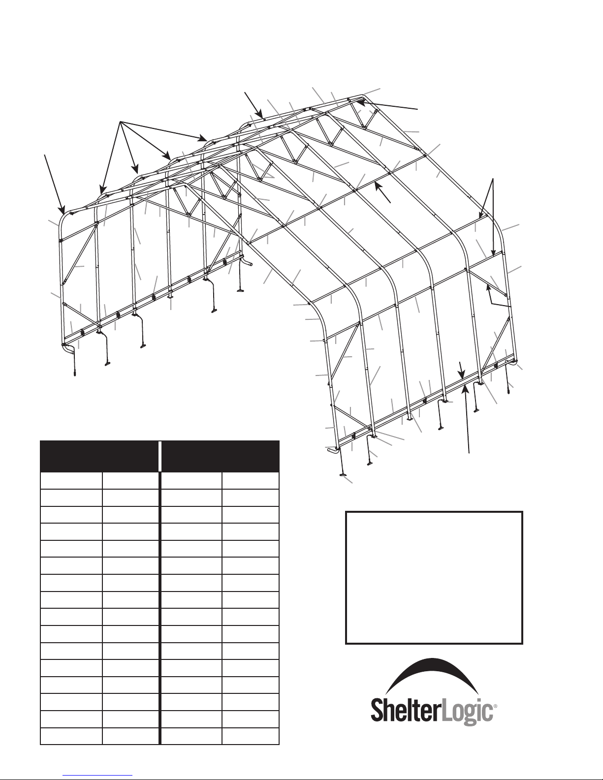
26'W x 16'H Peak Style Frame Assembly
Please read and understand instructions completely before assembly.
Lay out frame parts as shown.
1
2
14
16
12
15
16
7
4
23
9
18,13,16
8
21
12
15
16
8
7
14
30
1
18,13,16
22
26
25
8
3,28,16
5
4
18,13,16
Top Rail
1
7
22
17
13
16
Cross Rails
Cover
Rail
9
9
9
9
9
23
24
11
31
9
12
28
10
16
14
19
16
Cover
Rail
31
10
14
9
12
15
16
16
11
Base Rail
End Rib
2
21
30
Assembly
Reference #
Middle Ribs
22
26
25
31
8
9
Mfg.
Part #
1
6
23
11
24
End Rib
8
3
13
16
10
14
16
Assembly
Reference #
29,16
9
9
5
1
18,13,16
17,13,16
4
11
14
7
22
12
15
16
Mfg.
Part #
26
25
31
9
12
28
16
2
23
Wind Brace
21
19
1 800384 17 11106
2 800386 18 11107
3 800383 19 00828
4 800839 20 00825
5 800391 21 800388
6 800390 22 800434
7 11105 23 800438
8 11104 24 800387
9 11102 25 800439
10 800088 26 800442
11
WB601RS24
27
12 800372 28 11134
13 11130 29 11133
14 11131 30 802051
15 800454 31 802050
16 00690
19
ATTENTION:
FOR MISSING OR
REPLACEMENT PARTS
OR QUESTIONS,
PLEASE CONTACT
CUSTOMER SERVICE:
1.800.524.9970
CANADA 1.800.559.6175
WB602RS1
05_10A163_B1Page 3
Page 4
NOTE: FRAME EXTENSION KIT
Your model may have more middle ribs than shown in the illustration on pg.3. You will receive one extra rib for every
extra 4 ft. of building length that you purchase. The basic frame assembly will remain the same. The cover will be the
correct size for the length of the building.
26 ft.
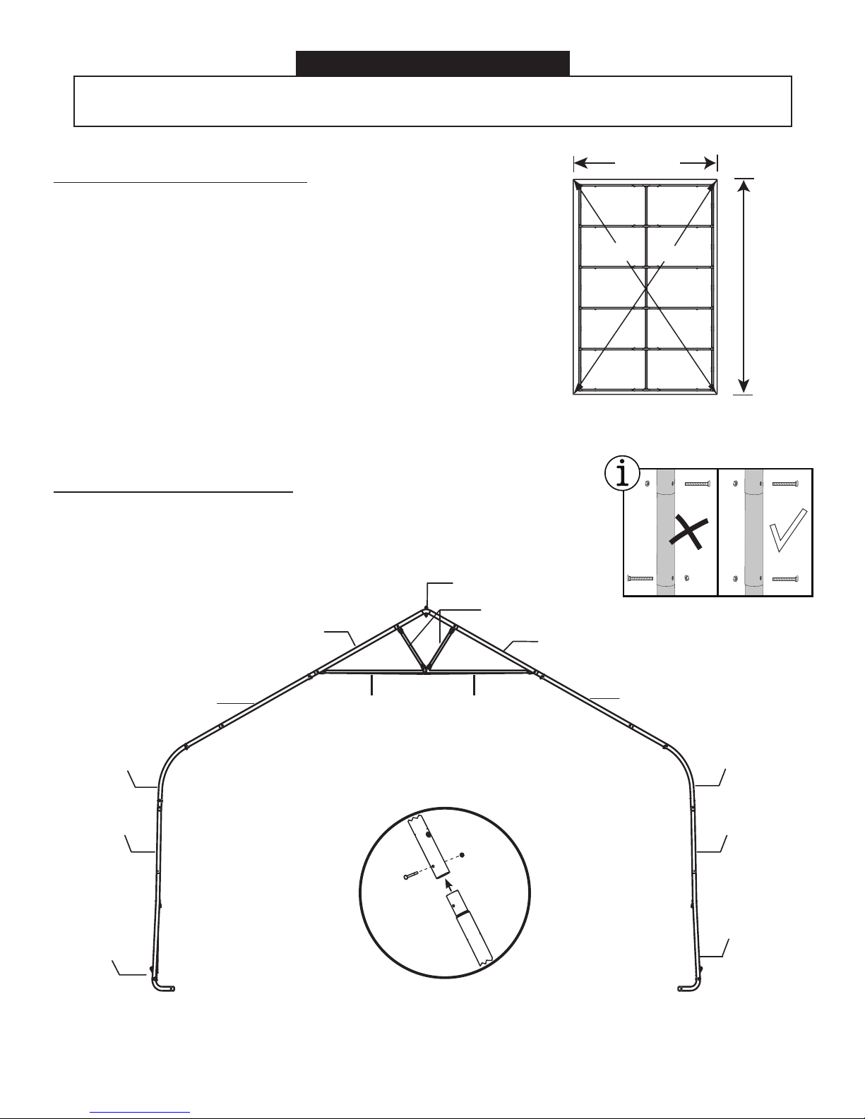
1. PLOTTING THE FRAME
Before building your shelter, you should choose a at area on
your property and plot your shelter.
A. Stake out the area for the shelter in the desired spot. The width of
the area should be at least equal to the width of the shelter and the
length should be equal to the length of the shelter Fig. 1.
B. Measure diagonally from corner to corner (A & B). These
measurements should be the same. If they are not equal the stakes
need to be adjusted until the width, length and inside measurements
are correct.
WIDTH
A
B
BUILDING
LENGTH
Fig.1
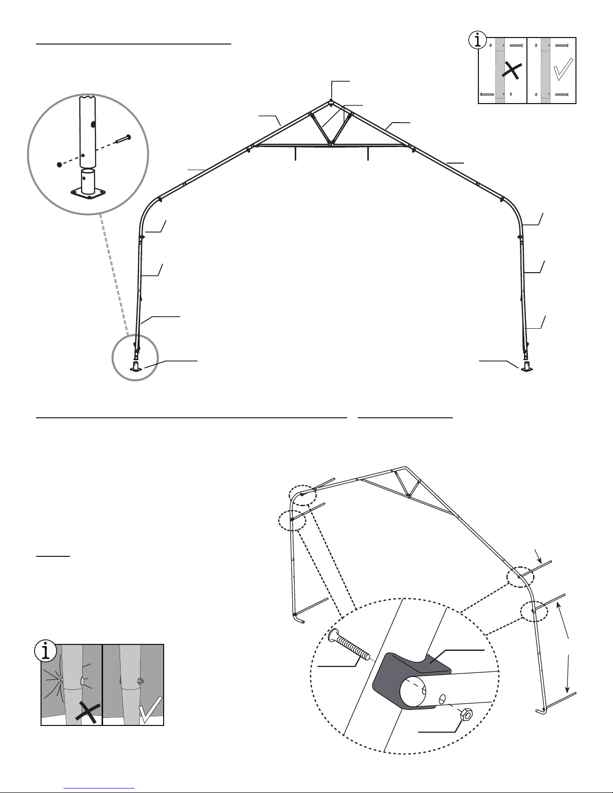
2. ASSEMBLE END RIBS
Assemble end ribs as shown in Fig. 2. Securely
fasten all of the joints with the hardware indicated.
800383
Fig.2
800384
800434
800391
800384
800434
800389800390
800386
800386
800438 800438
800388
800388
Use #11131
5/16" x 2 3/4" L
Bolts
05_10A163_B1Page 4
Page 5
3. ASSEMBLE MIDDLE RIBS
Assemble middle ribs as shown in Fig. 3. Securely
fasten all of the joints with the hardware indicated.
800383
800387
00690
Fig.3
11131
800859
800384
800434
800384
800434
800389800390
800386
800391
Use #11131
5/16" x 2 3/4" L
800438
Bolts
800387
800859 800859
800386
800438
800387
4. INSTALL SIDE RAILS AND SHELTERLOCK® STABILIZERS
A. Place assembled rst end rib in the staked area. Place the ShelterLocks® (800372) on the uprights
as shown in Figure 4. From the outside of the rib insert the bolt through the upright and then through the
ShelterLock®.
B. Place the rst Side Rails (11104) over the
bolts and nest them into the ShelterLocks®. Install
the nut onto the bolt and HAND TIGHTEN THE
BOLT THAT CONNECTS TO THE END RIB.
NOTE: Sliding Cover Rails (11105) should be
attached to frame after Step 8, once cover is
placed over the frame. See Step 9.
Fig.4
800372
800454
11104
11104
00690
05_10A163_B1Page 5
Page 6
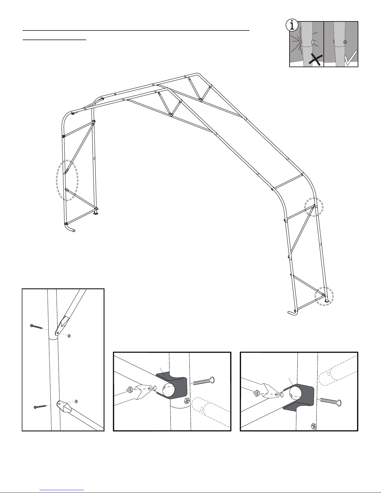
5. CONNECT THE FIRST MIDDLE RIB AND INSTALL
WIND BRACES
Attach Wind Braces 800439 and 800442 between the end rib and the rst middle
rib as shown in Figure 5.
Bolts should be inserted facing inside of the shelter.
Fig.5
800442
A
A
1113 1
800439
800442
00690
B
1110 4
00690
800372
1113 4
C
800439
800372
B
800442
800439
C
1110 2
00690
800442
1113 1
800439
1110 2
00690
1110 4
1113 4
05_10A163_B1Page 6
Page 7
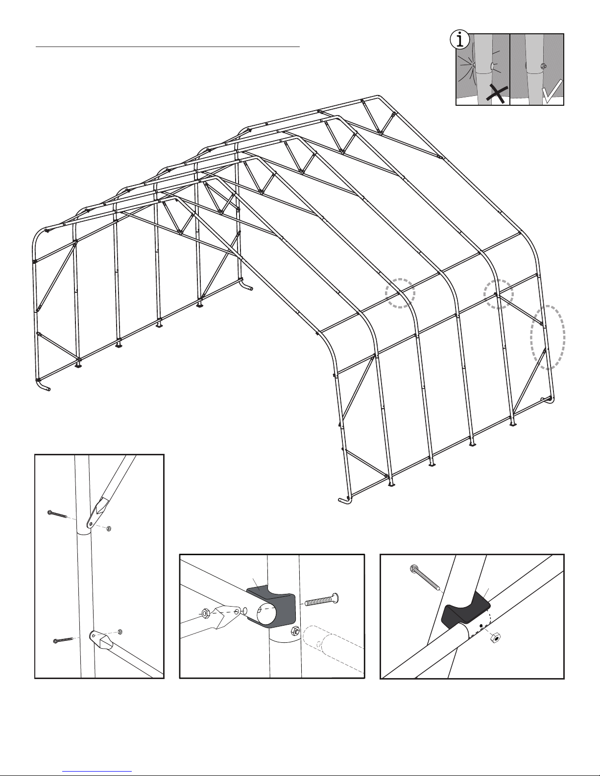
6. CONNECT THE REMAINING RIBS
A. Use Side Rails 11102 to connect remaining ribs and rear end rib.
B. Use Wind Braces 800439 and 800442 between the end rib and the last middle
rib as shown in Fig. 6.
Fig.6
11102
11102
A
1113 1
800442
00690
B
11102
11102
C
11102
11102
B
11102
11102
11102
C
11102
11102
800442
11102
A
800439
1110 4
00690
00690
800442
1113 1
800439
800372
1113 4
1110 2
800454
1110 2
800372
00690
1110 2
05_10A163_B1Page 7
Page 8
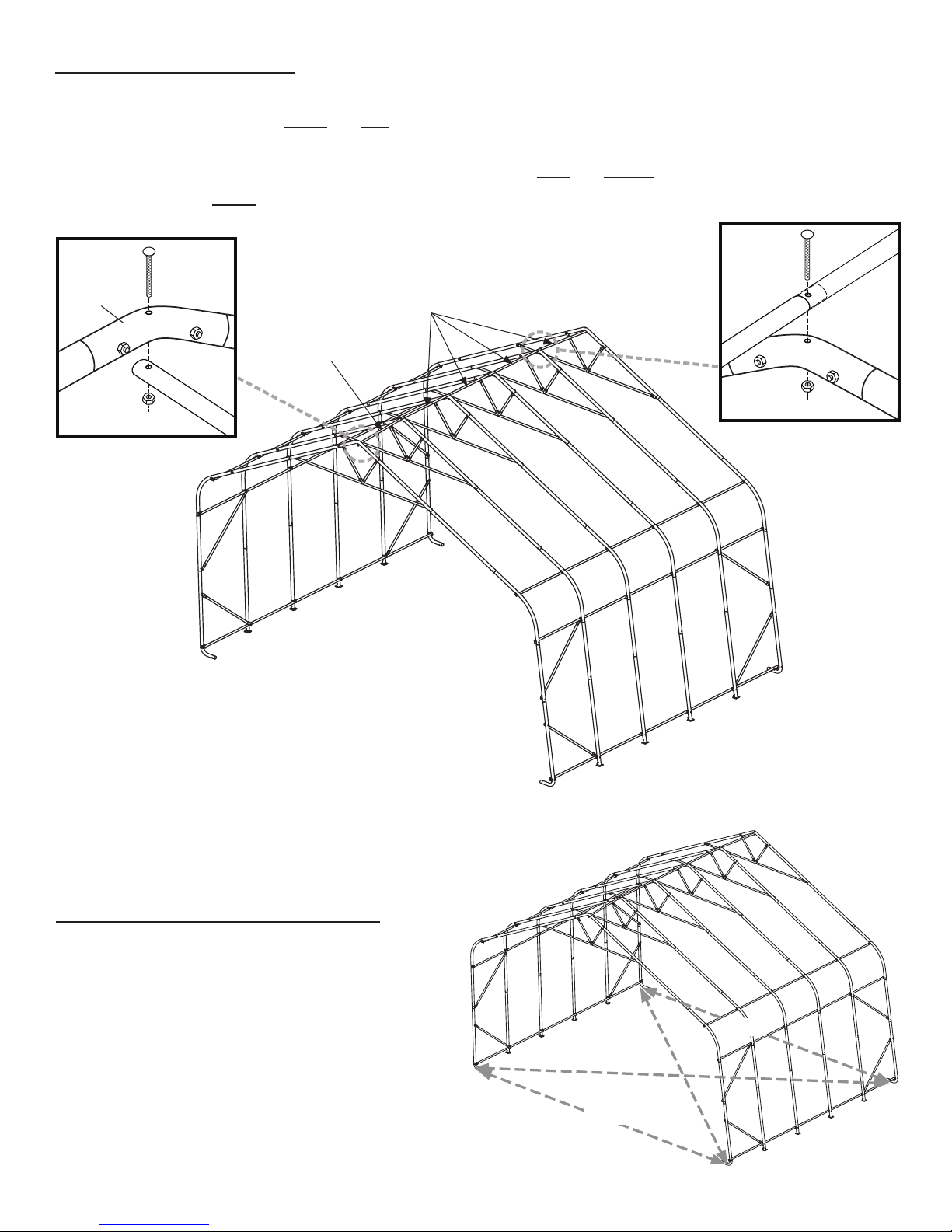
7. INSTALL TOP RAIL:
As with the Side Cross Rails, Use #11104 and #11102 Rails to make the Top Cross Rail:
A. Place the rst rail (#11104) under the end rib and secure it with bolt #11134 as shown in Fig.7A. HAND-
TIGHTEN this bolt.
B. Connect the rails to each other, laying the #11102 cross rails over the middle ribs. Use bolt #11133. Fig.7B
C. Place the last rail under the rear end rib. HAND-TIGHTEN this bolt.
Fig.7A
800383
00690
1113 4
11104
11102
11133
11102
Fig.7B
11102
00690
8. SQUARING UP THE FRAME
A. Be sure the frame is in its nal location, which
needs to be as at and level as possible.
B. Measure across opposite corners.
These distances must be equal to within 1 inch.
C. Check that the front and rear of the frame
measures 26 feet in width.
Fig.8
26 ft.
26 ft.
05_10A163_B1Page 8
Page 9

9. INSTALL EASY-HOOK EARTH ANCHORS:
A. The anchors should be positioned at the four corners and the remaining should be spaced evenly on both
sides of the shelter.
B. Using the provided steel driving rod and a sledge hammer, drive each anchor into the ground leaving
approximately 8 inches of cable exposed above the surface.
C. Wrap the cable around the driving rod and pull up on the cable to set the anchor.
D. After the anchors are rmly set, wrap the cable around the foot, then close with a cable clamp. Be sure to
remove all slack from cable.
If the ground is too hard, dig a hole
with a shovel or post hole tool.
Optional: Fill with cement.
For best results, ShelterLogic®
recommends using one Easy
Hook™ Drive Anchor at each
leg for a stronger, more secure
installation.
Fig.9
WARNING: Serious injury to persons or property
could result if cover is installed and shelter is not
completed and is left unattended. Shelter must
be securely anchored until completed.
05_10A163_B1Page 9
Page 10

10. END AND DOOR PANEL INSTALLATION
A. Hold end panel at the top center with white inner surface facing inside of the shelter. (If you purchased the white cover,
the inner face has the visible weld seams at the webbing pocket.) Wrap the edges of the fabric panel around the
end rib.
B. Disconnect top cross rail (the horizontal pipes that run from front to back along the top) from the end rib. Pull the
webbing (the black strap) below the cross rail. Reattach the top cross rail to the end rib.
C. Remove the nut from the side rail and carefully pull the side rail away from the ShelterLock® (pull away only enough to
pass the webbing through the connection). If this connection has the wind brace on it remove the wind brace end
before pulling the side rail. Replace the cross rail and wind brace. Replace the nut and tighten. Repeat this on the
other side.
D. At the bottom, where the webbing exits the pocket on each side of end panel, pull webbing to remove the slack. Be
careful not to pull the webbing through the other side of the webbing pocket.
E. Insert the “S”- Hook on ratchet into hole on the leg bend. Insert the webbing into the spindle of the ratchet and pull tight.
Wind the ratchet so that the webbing overlaps itself.
Position the end panel so that it is centered on the building before fully tightening the end panel.
F. Tighten ratchets, alternating from one side to the other, until the end panel is centered and tight.
NOTE:
Keep Zippers closed when tightening end panels.
WRAP END PANEL EDGES OVER AND AROUND PIPE TOWARDS INSIDE OF FRAME.
IMPORTANT!
Fig.10
ZIPPERS
DO NOT INSERT ANY PIPES
INTO THESE POCKETS.
TOP CROSS
RAIL
SIDE
CROSS RAILS
WIND
BRACE
WEBBING
WRAP END
PANEL
EDGES
TO INSIDE
OF FRAME
INSIDE VIEW OF END RIB SIDE VIEW OF END RIB
Thread
Webbing
Into
Ratchet
Webbing
and
Ratchets
Securing
End Panel
05_10A163_B1Page 10
Page 11

11. INSTALLING THE COVER ON THE FRAME
A. Lay the cover on the ground next to the
frame with the inside of the cover (the side
with the pipe pockets) facing down and the
webbing on the front and rear of the corner
of the building. Position the cover so that it is
centered to the frame, front to back. Fig. 11A
B. Fold over the side closest to the frame so
the pipe pocket is now accessible. Insert a
cover pipe at the rst middle rib from the front
and the rst middle rib from the rear so that it
is inserted in the pipe pocket on both ends of
the pipe but the center of the pipe is exposed.
For long buildings it may be necessary to use
additional pipes in the middle. Fig. 11B.
C. Tie the rope on each of the exposed pipes
and throw the other end of the rope over the
frame. Fig. 11C.
D. Move to the other side of the frame and
pull the cover over the frame with the rope.
This may require two or more people.
Fig. 11D.
END PANELS
NOT SHOWN
FOR CLARITY.
Fig.11A
Fig.11B
Fig.11C
NOTE: CHECK THAT YOUR COVER IS
CORRECTLY PLACED ON THE FRAME.
The ShelterLogic® logo should line up on the left front and
right rear corners near the top rail. If the logo is not legible,
the cover has not been put on the frame correctly.
Fig.11D
05_10A163_B1Page 11
Page 12

11. INSTALLING THE COVER ON THE FRAME - continued
E. After cover is centered on frame, insert a Cover Rail (#11105) into each pocket on the inside of the cover in
the roof.
F. Use 3-Way (#11106) and 4-Way (#11107) Clamps to connect them to the ribs. Hand-tighten bolts (#11130).
See Figure 11F.
NOTE: To avoid damage to fabric, face bolt heads towards cover.
G. Using cover rails, pull top portion of cover tightly downward and outward from the
center and tighten bolts.
Middle Rib Cross Rail ClampsEnd Rib Cross Rail Clamps
1110 6
00690
1113 0
1110 7
1113 0
00690
Fig.11F
COVER NOT
SHOWN FOR
CLARITY.
1110 5
1110 5
1110 5
1110 5
1110 5
05_10A163_B1Page 12
Page 13

11. INSTALLING THE COVER ON THE FRAME - continued
H. At the corners, insert the “S”- Hook on ratchet into hole on the leg bend. Insert the webbing into the spindle
of the ratchet and pull tight. Wind the ratchet so that the webbing overlaps itself. See Figure 11G.
I. Repeat these steps on the opposite side, then repeat this on the back side of the shelter.
J. Adjust the cover front to back so that it is centered. Install the bottom cover rails (#802051 and #802050) by
inserting them into the pipe pockets on each side of the cover. An opening allows the webbing to wrap around
cover rail and base rail to secure the cover. Tighten webbing using ratchet as shown in Figure 11J
K. Tighten all of the ratchets. Do this in an “X” pattern to be sure it is tightened evenly.
Fig.11G
Thread
Webbing
Into
Ratchet
Webbing
and
Ratchets
Securing
Cover
Fig.11H
NOTE: CHECK THAT YOUR COVER IS CORRECTLY PLACED ON THE FRAME.
The ShelterLogic® logo should line up on the left front and right rear corners. If the logo does not read correctly, the cover
has not been put on the frame correctly.
CORRECT
Fig.11I
INCORRECT
Cover Tightening Tip
Check and
tighten Ratchets
and Cross Rails
monthly to ensure
the cover is tight.
TIGHTEN COVER DOWN
WITH RATCHET, STARTING
AT ONE END WORKING TO
OPPOSITE END ON BOTH
SIDES.
ASSEMBLED
COVER RAIL
Fig.11J
05_10A163_B1Page 13
Page 14

Abri à toit pointu, 7,9 m (larg.) x 4,9 m (haut.)
Guide d'assemblage
+
/
-
18 po
45 cm
Veuillez lire TOUTES les instructions avant d'entreprendre l'assemblage. Cet abri DOIT être bien ancré.
CECI EST UNE STRUCTURE TEMPORAIRE, IL N'EST PAS RECOMMANDÉ D'EN FAIRE UNE STRUCTURE PERMANENTE.
Avant de commencer : Il faut 5 personnes ou plus pour le montage.
Le temps de montage dépend de la longueur de votre bâtiment.
Veuillez prévoir environ 15 minutes pour chaque pied de longueur du bâtiment.
150 Callender Road
Watertown, CT 06795
www.shelterlogic.com
1/15/13
1-800-524-9970
Canada :
1-800-559-6175
Page 14 05_10A163_B1
Page 15

ATTENTION :
Cet abri est fabriqué avec des matériaux de qualité. Il est conçu en fonction de la toile adaptée ShelterLogic
ShelterLogic
la sève, les excréments d’animaux ou d’oiseaux et la neige légère. Veuillez ancrer adéquatement cette structure ShelterLogic
®
Corp. offrent de l’espace de rangement et de la protection contre les dommages causés par le soleil, la pluie légère,
®
Corp. fournie. Les abris
®
Corp.
Consultez le guide pour connaître les détails sur l’ancrage. Il incombe à l’utilisateur d’assurer un ancrage adéquat et de garder la
toile bien tendue et exempte de neige ou de débris. Veuillez lire et vous assurer de bien comprendre les détails de l’installation, les
avertissements et les mises en garde avant d’entreprendre l’installation. Pour toute question, téléphonez au service à la clientèle au
numéro ci-dessous. Veuillez aussi consulter la che de garantie se trouvant dans l’emballage.
DANGER :
Avant d’entreprendre l’installation, vériez tous les règlements municipaux concernant les abris
temporaires. Choisissez soigneusement l’emplacement de l’abri. DANGER : Tenez-vous éloigné
des ls électriques. Évitez les lignes électriques, les branches d’arbres et les autres types de
structures. Avant de creuser, vériez la présence de tuyaux ou de ls enfouis. N’installez PAS cet abri
à proximité d’un toit ou de toute autre structure pouvant laisser tomber de la neige, de la glace ou des
débris. Ne suspendez AUCUN objet au toit ou aux câbles de soutien.
AVERTISSEMENT :
Risque d’incendie. Ne fumez PAS et n’utilisez AUCUN dispositif produisant des ammes (p. ex., un
barbecue, un foyer, une friteuse, un fumoir ou une lanterne) à proximité de l’abri. Ne rangez PAS des
liquides inammables (essence, kérosène, propane, etc.) à proximité de l’abri. N’exposez pas le dessus
ou les parois de l’abri au feu ou à toute source d’incendie.
ATTENTION :
Soyez PRUDENT au moment de monter l’armature. Portez des lunettes de sécurité durant l’installation. Boulonnez les mâts
supérieurs durant l’assemblage. Prenez garde aux extrémités des mâts.
ANCRAGE ET INSTALLATION DE L’ARMATURE :
IL INCOMBE À L’UTILISATEUR D’ASSURER L’ANCRAGE ADÉQUAT DE L’ARMATURE.
ShelterLogic
naturelles. Tout abri n’étant pas ancré solidement risque de s’envoler et de causer des dommages, ce qui n’est pas couvert par la
garantie. Vériez périodiquement les ancrages pour assurer la stabilité de l’abri. ShelterLogic
d’un abri qui s’envole. REMARQUE : La toile de l’abri peut être retirée rapidement pour être entreposée en prévision de mauvais
temps. Si des vents forts ou du mauvais temps sont prévus pour votre région, nous vous recommandons d’enlever la toile de l’abri.
®
Corp.
n’assume aucune responsabilité pour les dommages causés à l’abri ou à son contenu par les catastrophes
®
Corp. ne peut être tenue responsable
PIÈCES DE RECHANGE ET COMMANDES SPÉCIALES :
Des pièces de rechange et des accessoires d’origine ShelterLogic
d’ancrage pour presque toute utilisation, des toiles de rechange, des ensembles de parois, des nécessaires d’aération ou d’éclairage,
des pièces d’armature, des portes à glissière, etc. Tous ces articles sont expédiés directement chez vous à partir de l’usine.
QUESTIONS, RÉCLAMATIONS OU COMMANDES SPÉCIALES – LIGNE D’AIDE DU SERVICE À LA CLIENTÈLE :
ÉTATS-UNIS : 1-800-524-9970 SERVICE À LA CLIENTÈLE INTERNATIONAL : 001-860-945-6442 CANADA : 1-800-559-6175
HEURES D’OUVERTURE : DU LUNDI AU VENDREDI DE 8 H 30 À 20 H (HE), SAMEDI ET DIMANCHE DE 8 H 30 À 17 H (HE)
®
Corp. sont disponibles à l’usine, notamment des nécessaires
ENTRETIEN ET NETTOYAGE :
Une toile bien tendue assure une longue durée utile. Gardez toujours la toile bien tendue. Une toile desserrée
accélère la détérioration du tissu. Enlevez sans attendre toute accumulation de débris sur le toit à l’aide d’un
balai, d’une vadrouille ou d’un autre outil souple. Soyez très prudent au moment d’enlever la neige de la toile.
Enlevez-la toujours à partir de l’extérieur de la structure. N’utilisez PAS d’outils rigides comme des râteaux
ou des pelles pour enlever la neige, car ils risqueraient de perforer la toile. N’utilisez PAS de javellisants ou
d’abrasifs pour nettoyer la toile. Utilisez tout simplement de l’eau savonneuse pour nettoyer la toile.
GARANTIE :
Cet abri offre une garantie limitée contre les défauts de fabrication. ShelterLogic® Corp. garantit à l’acheteur initial que s’il est installé et utilisé
adéquatement, cet article et toutes ses pièces sont exempts de défaut de fabrication pendant une période de :
1 AN POUR LA TOILE, LES PANNEAUX D’EXTRÉMITÉ ET L’ARMATURE.
La période de garantie est calculée à partir de la date d’expédition par ShelterLogic® Corp. pour les achats faits directement à l’usine ou de la date
d’achat chez un revendeur autorisé (veuillez conserver votre reçu d’achat). Si cet article ou une de ses pièces est jugé défectueux ou qu’il est manquant
au moment de la réception, ShelterLogic® Corp. réparera ou remplacera, à sa discrétion, toute pièce défectueuse sans frais pour l’acheteur initial.
Toute pièce remplacée ou réparée demeure couverte durant le reste de la période de garantie limitée initiale. Tous les frais d’expédition sont à la charge
du client. Les pièces et les composants de rechange sont expédiés contre remboursement. Veuillez conserver le matériel d’emballage initial pour l’envoi
de retour. Pour les achats faits chez un marchand local, toute réclamation doit être accompagnée d’une copie du reçu initial. Après l’achat, veuillez
remplir et expédier la che de garantie pour inscrire l’article. Veuillez consulter la che de garantie pour obtenir de plus amples renseignements.
Brevets Américains et brevets en instance : 6,871,614; 6,994,099; 7,296,584; D 430,306; D 415,571; D 414,564; D 409,310; D 415,572
090111
Page 15 05_10A163_B1
Page 16

Abri à toit pointu, 7,9 m (larg.) x 4,9 m (haut.) - Assemblage de l'armature
Veuillez lire et vous assurer de bien comprendre TOUTES les instructions avant
d'entreprendre l'assemblage.
Étalez les pièces de l'armature,
comme le montre l'illustration.
Nervures
centrales
Nervure
d'extrémité
2
21
25
30
8
N°
d'assemblage
22
26
31
9
23
24
N° de
pièce
1
6
11
1 800384 17 11106
2 800386 18 11107
8
10
14
16
d'assemblage
Nervure
d'extrémité
3
13
16
4
N°
14
11
29,16
9
17,13,16
22
N° de
pièce
7
5
1
18,13,16
12
15
16
1
9
9
1
18,13,16
4
18,13,16
7
7
14
16
8
2
12
15
16
8
23
14
25
30
21
12
15
16
8
3,28,16
5
4
18,13,16
Tube supérieur
1
17
13
16
7
22
Rails
latéraux
Rail de
22
26
19
toile
9
9
9
9
9
11
9
Rail de
toile
31
12
15
16
Rail de base
10
14
16
23
24
31
9
12
28
10
16
14
19
16
26
25
11
9
2
23
Contreventement
31
21
19
12
28
16
3 800383 19 00828
4 800839 20 00825
5 800391 21 800388
6 800390 22 800434
7 11105 23 800438
8 11104 24 800387
9 11102 25 800439
10 800088 26 800442
11
WB601RS24
27
12 800372 28 11134
13 11130 29 11133
14 11131 30 802051
15 800454 31 802050
16 00690
ATTENTION :
EN CAS DE PIÈCE MANQUANTE
ET POUR TOUTE PIÈCE DE
RECHANGE OU TOUTE QUESTION,
VEUILLEZ COMMUNIQUER AVEC
LE SERVICE À LA CLIENTÈLE :
1.800.524.9970
CANADA 1.800.559.6175
WB602RS1
Page 16 05_10A163_B1
Page 17

REMARQUE : NÉCESSAIRE DE RALLONGE D'ARMATURE
Votre abri peut comporter davantage de nervures centrales que l'illustration de la page 16. Vous recevez une
nervure additionnelle pour chaque section supplémentaire de 1,2 m. L'assemblage de l'armature de base reste le
même. La taille de la toile correspondra à la longueur de l'abri.
1. TRACEZ L'EMPLACEMENT.
Avant d’assembler l’abri, vous devez choisir une surface
plane et y tracer son emplacement.
A. Piquetez l’emplacement de l’abri à l’endroit choisi. La largeur de
l’emplacement doit être au moins égale à la largeur de l’abri et sa
longueur, à celle de l’abri (g. 1).
B. Mesurez la distance en diagonale entre les coins (A et B). Cette
distance doit être égale dans tous les cas. Sinon, les piquets doivent
être déplacés jusqu’à ce que la largeur, la longueur et les mesures
soient correctes.
2. ASSEMBLEZ LES NERVURES
D’EXTRÉMITÉ
Assemblez les nervures d'extrémité comme
le montre la g. 2. Serrez bien tous les joints
avec les xations illustrées.
7,9 m
LARGEUR
A
Longueur
B
de l'abri
Fig.1
800383
Fig.2
800384
800434
800391
800384
800434
800389800390
800386
800386
800438 800438
800388
800388
Utilisez les
boulons n° 11131
(5/16 x 2 3/4 po)
Page 17 05_10A163_B1
Page 18

3. ASSEMBLEZ LES NERVURES CENTRALES
Assemblez les nervures centrales comme le
montre la g. 3. Serrez bien tous les joints
800383
avec les xations illustrées.
800391
800384
800387
800384
00690
11131
800434
800434
800389800390
800859
800386
800386
Utilisez les
800438
boulons n° 11131
(5/16 x 2 3/4 po)
800438
Fig.3
800387
800387
800859 800859
4. INSTALLEZ LES RAILS LATÉRAUX ET LES STABILISATEURS SHELTERLOCK
A. Placez la nervure avant à l'emplacement piqueté. Placez les stabilisateurs ShelterLock (800372) sur les
montants comme le montre la g. 4. À partir de l'extérieur de la nervure, insérez le boulon dans le montant,
puis dans le stabilisateur ShelterLock®.
®
B. Placez les premiers rails latéraux (11104) sur
les boulons et logez-les dans les stabilisateurs
ShelterLock. Posez un écrou sur chaque boulon
et SERREZ À LA MAIN LE BOULON QUI
RELIE LA NERVURE D'EXTRÉMITÉ.
REMARQUE : Les rails de toile coulissants
(11105) doivent être xés à l'armature après
l'étape 8, une fois que la toile est placée sur
l'armature. Voir l'étape 9.
Fig.4
800454
00690
800372
11104
11104
Page 18 05_10A163_B1
Page 19

5. RELIEZ LA PREMIÈRE NERVURE CENTRALE ET
INSTALLEZ LES CONTREVENTEMENTS
Fixez un contreventement (800439) entre la nervure d'extrémité et la première
nervure centrale comme le montre la gure 5.
Les boulons xés aux traverses doivent être orientés vers l'intérieur de l'abri.
Fig.5
800442
A
A
1113 1
800439
800442
00690
B
1110 4
00690
800372
1113 4
C
800439
800372
B
800442
800439
C
1110 2
00690
800442
1113 1
800439
00690
1110 2
Page 19 05_10A163_B1
1110 4
1113 4
Page 20

6. RELIEZ LES NERVURES RESTANTES
A. Utilisez les rails latéraux (11102) pour relier les nervures restantes et la nervure
d'extrémité arrière.
B. Placez des contreventements (800439) entre la nervure d'extrémité et la dernière
nervure centrale comme le montre la Fig. 6.
Fig.6
11102
11102
A
1113 1
800442
00690
B
11102
11102
C
11102
11102
B
11102
11102
11102
C
11102
11102
800442
11102
A
800439
1110 4
00690
00690
800442
1113 1
800439
800372
1113 4
1110 2
Page 20 05_10A163_B1
800454
1110 2
800372
00690
1110 2
Page 21

7. INSTALLEZ LA TRAVERSE SUPÉRIEURE
À l'instar des traverses latérales, utilisez les traverses 11104 et 11102 pour composer la traverse
supérieure.
A. Placez la première traverse (11104) sous la nervure d'extrémité et xez-la avec le boulon 11134 comme le
montre la Fig.7A. Serrez ce boulon À LA MAIN.
B. Reliez les traverses entres elles en plaçant les traverses 11102 sur les nervures centrales. Utilisez le boulon
11133 (voir la Fig. 7B).
C. Placez la dernière traverse sous la nervure d'extrémité arrière. Serrez ce boulon À LA MAIN.
Fig.7A
800383
00690
1113 4
11104
11102
11133
11102
Fig.7B
11102
00690
8. METTEZ L’ARMATURE EN ÉQUERRE
A. Placez l’armature à son emplacement dénitif,
dont la surface doit être aussi plane que possible.
B. Mesurez la distance qui sépare les coins
opposés. Cette distance doit être la même à 1
pouce près.
C. Assurez-vous que les sections avant et arrière
de l’armature mesurent 7,9 m de largeur.
Fig.8
26 ft.
26 ft.
Page 21 05_10A163_B1
Page 22

9. INSTALLEZ LES ANCRAGES EASY-HOOK
A. Des ancrages doivent être placés aux quatre coins, puis le reste des ancrages doivent être espacés
également des deux côtés de l'abri.
B. En utilisant la tige d'acier fournie et une masse, enfoncez chaque ancrage dans le sol en laissant dépasser
environ 8 po de câble au-dessus de la surface.
C. Enroulez le câble sur la tige et tirez sur le câble pour placer l'ancrage.
D. Après avoir bien installé les ancrages, enroulez le câble sur les pieds, puis xez le câble à l'aide d'un serre-
câble. Assurez-vous de bien tendre le câble.
Si le sol est trop dur, creusez un trou
à l’aide d’une pelle ou d’une bêchetarière. Option : Remplissez le trou
de ciment.
Pour de meilleurs résultats,
ShelterLogic® recommande
d’utiliser une Easy HookMC
soit un pour chaque pied de
l’armature, an d’obtenir une
installation plus résistante et
sécuritaire.
Fig.9
AVERTISSEMENT : Des blessures graves ou
des dommages pourraient se produire si la
toile est installée et laissée sans surveillance
alors que le montage de l'abri n'est pas encore
terminé. L'abri doit être ancré adéquatement
durant le processus de montage.
Page 22 05_10A163_B1
Page 23

10. INSTALLEZ LE PANNEAU D'EXTRÉMITÉ ET LE PANNEAU DE PORTE
A. Placez le panneau d’extrémité au centre de la partie supérieure de l’abri en orientant la surface interne vers l’intérieur
de l’abri (pour la toile blanche, la surface interne est pourvue de joints de soudure visibles au fourreau de la courroie).
Faites passer le rebord du panneau en tissu autour de la nervure d’extrémité.
B. Débranchez la traverse supérieure (tuyaux horizontaux allant de l’avant à l’arrière de la partie supérieure de l’abri) de
la nervure d’extrémité. Faites passer la courroie (sangle noire) sous la traverse. Rebranchez la traverse supérieure à la
nervure d’extrémité.
C. Enlevez l'écrou de la traverse latérale et éloignez délicatement cette dernière de la pièce ShelterLock® (éloignez-
la juste assez pour pouvoir faire passer la sangle dans le raccord). Si ce raccord comporte le contreventement,
enlevez l'extrémité de ce dernier avant de tirer sur la traverse latérale. Replacez la traverse et le contreventement.
Resserrez l'écrou. Répétez cette étape de l'autre côté.
D. Dans le bas, à l’endroit où la courroie dépasse du fourreau de chaque côté du panneau d’extrémité, tirez sur la
courroie pour la tendre. Lorsque vous tirez sur la courroie, faites attention pour ne pas la faire entrer dans le
fourreau de l’autre côté.
E. Insérez le crochet en « S » de la bride à cliquet dans le trou pratiqué dans le montant recourbé. Insérez la courroie
dans la bobine du cliquet et tirez sur la courroie. Actionnez le cliquet de sorte que la courroie se chevauche elle-même.
Centrez le panneau d’extrémité sur l’abri avant de le serrer dénitivement.
F. Serrez les cliquets en alternant d’un côté à l’autre jusqu’à ce que le panneau d’extrémité soit bien centré et tendu.
REMARQUE :
Laissez les glissières fermées pendant que vous serrez les panneaux d’extrémité.
FAITES PASSER LE REBORD DU PANNEAU D’EXTRÉMITÉ PAR-DESSUS ET AUTOUR DU
TUYAU VERS L’INTÉRIEUR DE L’ARMATURE.
IMPORTANT!
Fig.10
GLISSIÈRES
N’INSÉREZ AUCUN TUYAU DANS CES FOURREAUX.
TRAVERSE
SUPÉRIEURE
TRAVERSES
LATÉRALES
CONTREVENTEMENT
COURROIE
FAITES
PASSER LE
REBORD DU
PANNEAU
D’EXTRÉMITÉ
VERS
L’INTÉRIEUR
DE
L’ARMATURE
VUE DE L’INTÉRIEUR DE LA NERVURE D’EXTRÉMITÉ VUE DE PROFIL DE LA
Insérez la
courroie
dans le
cliquet
NERVURE D’EXTRÉMITÉ
Courroie
et cliquets
retenant le
panneau
d’extrémité
Page 23 05_10A163_B1
Page 24

11. INSTALLEZ LA TOILE SUR L’ARMATURE
A. Étalez la toile sur le sol à côté de l’armature en
plaçant l’intérieur de la toile (côté avec les fourreaux
pour tuyaux) vers le bas et les courroies avant et
arrière vers les coins de l'abri. Centrez la toile entre
l’avant et l’arrière de l’armature (g. 11A).
B. Repliez le côté le plus proche de l'armature, de
sorte que le fourreau pour tuyau soit accessible.
Insérez un tuyau de toile à la première nervure
centrale à partir de l'avant et à la première nervure
centrale à partir de l'arrière, de sorte que les deux
extrémités du tuyau soient insérées dans le fourreau
et que le centre du tuyau soit exposé. Pour un abri
allongé, il pourrait s'avérer nécessaire d'utiliser des
tuyaux additionnels au centre (g. 11B).
C. Fixez une corde à chaque tuyau exposé, puis
lancez l'autre extrémité de chaque corde par-dessus
l’armature (g. 11C).
D. Allez de l’autre côté de l’armature et placez la
toile sur l’armature en tirant sur les cordes. Cette
opération peut nécessiter deux personnes ou plus
(g. 11D).
PANNEAUX
D'EXTRÉMITÉ
NON ILLUSTRÉS
Fig.11A
Fig.11B
Fig.11C
REMARQUE : ASSUREZ-VOUS QUE LA
TOILE EST PLACÉE CORRECTEMENT
SUR L'ARMATURE.
Le logo ShelterLogic® doit être aligné avec les coins
avant gauche et arrière droit près du rail supérieur. Si
le logo n'est pas bien visible, la toile n'est pas placée
correctement sur l'armature.
Fig.11D
Page 24 05_10A163_B1
Page 25

11. INSTALLEZ LA TOILE SUR L'ARMATURE (suite)
E. Une fois la toile centrée sur l'armature, insérez un rail de toile (11105) dans chaque fourreau à l'intérieur de
la toile, au plafond.
F. Utilisez les brides à 3 voies (11106) et à 4 voies (11107) pour les xer aux nervures. Serrez les boulons
(11130) à la main. Voir la Figure 11F.
REMARQUE : Pour éviter d'endommager la toile, orientez la tête des boulons
vers la toile.
G. En utilisant les rails de toile, tirez la partie supérieure de la toile vers le bas et vers
l'extérieur à partir du centre, puis serrez les boulons.
Brides de traverse pour nervure centraleBrides de traverse pour nervure d'extrémité
1110 6
00690
1113 0
1110 7
1113 0
00690
Fig.11F
TOILE
NON MONTRÉE
1110 5
1110 5
1110 5
1110 5
1110 5
Page 25 05_10A163_B1
Page 26

11. INSTALLEZ LA TOILE SUR L’ARMATURE - suite
H. Dans les coins, insérez le "S" - Crochet à cliquet dans le trou sur le coude jambe. Insérez la sangle dans
l'axe de la clé à cliquet et tirez fermement. Enroulez le rochet de sorte que la sangle elle-même chevauche.
Voir Figure 11G.
I. Répétez ces étapes sur le côté opposé, puis répétez cette sur la face arrière de l'abri.
J. Ajuster le toile avant à l'arrière, an qu'il soit centré. Installez les rails toile inférieure (# 802051 et # 802050)
en les insérant dans les poches de tuyau de chaque côté de la toile. Une ouverture permet à la sangle pour
envelopper le rail de recouvrement et le rail de base pour xer le couvercle. Serrez la sangle à cliquet en utilisant comme illustré dans la Figure 11J
K. Serrez tous les cliquets. Pour ce faire, dans un "X" pour être sûr qu'il est serrés uniformément.
Fig.11G
Insérez la
courroie
dans le
cliquet
Courroie
et cliquets
retenant le
panneau
d’extrémité
Fig.11H
REMARQUE : ASSUREZ-VOUS QUE LA TOILE EST PLACÉE CORRECTEMENT SUR
L'ARMATURE.
Le logo ShelterLogic® doit être aligné avec les coins avant gauche et arrière droit. Si le logo n'est pas bien visible, la toile
n'est pas placée correctement sur l'armature..
CORRECT
INCORRECT
Fig.11I
Conseil de serrage
pour la toile
Vériez les cliquets et les
traverses chaque mois et
serrez-les au besoin pour
vous assurer que la toile
est bien tendue.
SERREZ LA TOILE AVEC
LES CLIQUETS À PARTIR
D'UNE EXTRÉMITÉ JUSQU'À
L'EXTRÉMITÉ OPPOSÉE DES
DEUX CÔTÉS.
Fig.11J
RAIL DE TOILE
ASSEMBLÉ
Page 26 05_10A163_B1
 Loading...