

Page 1
Run-In-Shed Assembly Manual
800.524.9970
www.shelterlogic.com
150 Callender Road
Watertown, CT 06795
Please read instructions completely before assembly
12 x 20 x 8 Frame
1: 10224
2: 10225
3: 10226
4: 10273
5: 2030
6: 2031
7: 10110
8: 10111
9: 10112
10: 10205
11: 10270
12: 669
13: 10210
14: 10114
15: 10115
16. 800260
Frame Assembly Overview
Page 1
05-51331-0B 06/07/07
Page 2
Basic Frame Assembly
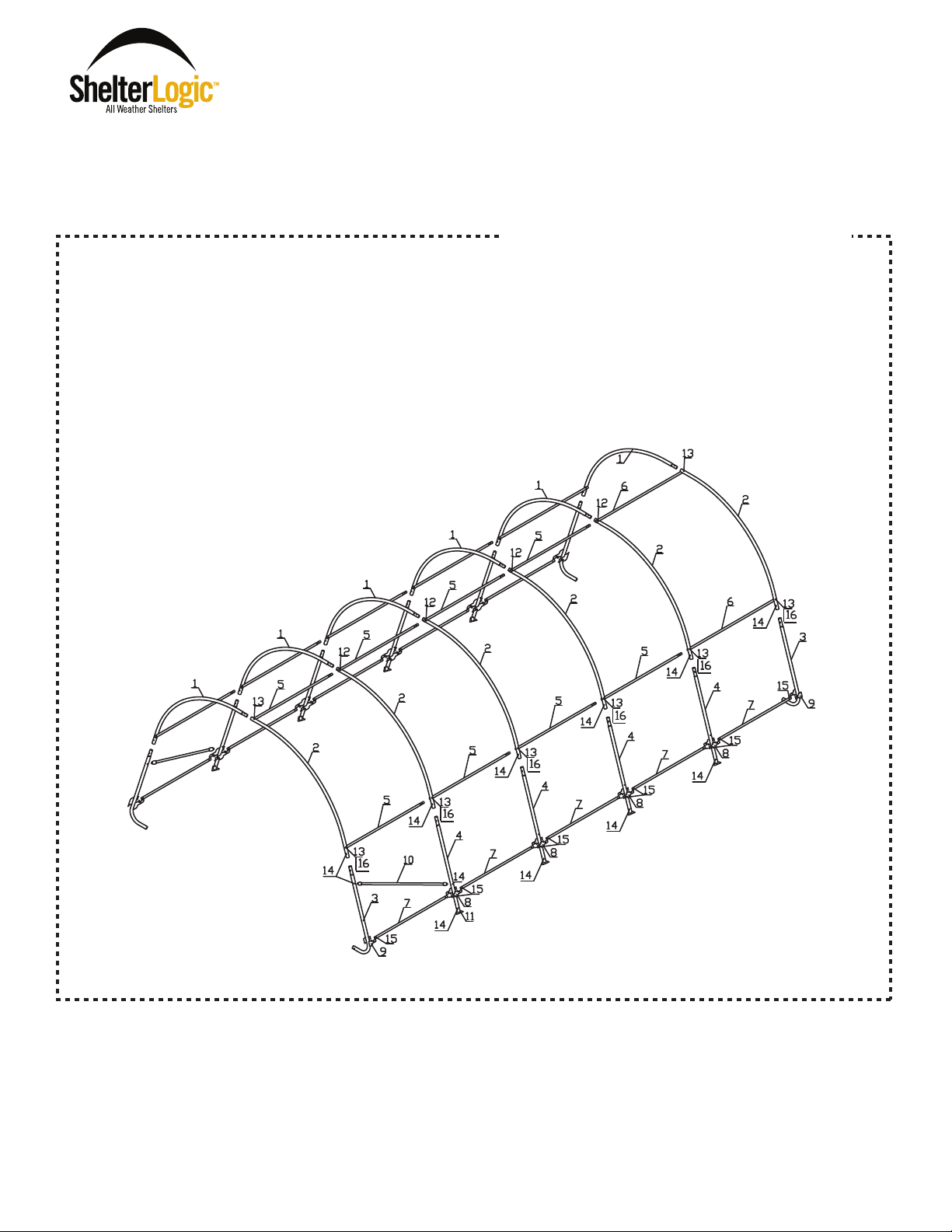
STEP 1
Fit together an end rib using the following parts (1) #10224 Bent Tube Swedged, (1) #10225 Bent Tube Plain and (2) #10226
Bent Corner Leg. Using (2) #10114 1/4" x 2" L Carriage Bolts and (2) #1010 1/4" Nuts securely fasten the joints of the
Corner legs to the bends. Lay this rib on the ground at the rear of your shelters designated location.
Fig.1
#10210
3" Bolts
2”
Bolts
STEP 2
Assemble a middle rib using the following parts (1) #10224 Bent Tube Swedged, (1) #10225 Bent Tube Plain and (2) #10273
Middle Upright Tube. Using (2) #10114 1/4" x 2" L Carriage Bolts (1) #669 1/4" x 3" Round Head Bolt and (3) #1010 1/4" Nuts
securely fasten the joints of the Corner legs to the bends. Lay this rib on the ground near the first end rib.
Fig.2
#669
3" Bolts
2”
Bolts
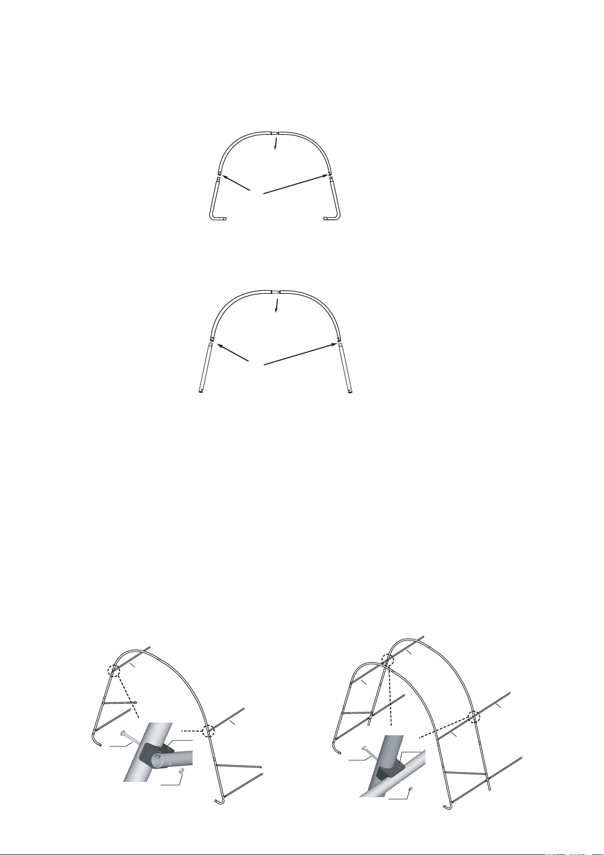
STEP 3
3A Stand the rear end rib vertically and lean against a permanent structure. Place a ShelterLock against the rib over the
hole for the cross rail just above the joint of the side bend and the extension. Insert a 1/4'' x 3''L Carriage Bolt through the
rib and ShelterLock with the head of the Bolt on the outside of the rib. Place the plain end of a #02030 Cross Rail onto
the bolt and rest it into the ShelterLock and secure it with a 1/4'' Nut. Next, attach a #10205 Wind Brace using a 1/4'' x 2''L
Carriage Bolt and Nut to each corner upright tube. Place (2) #10112 3-Way Connectors around the bent corner leg. Insert the
end of a #10110 Cover Rail Tube into the 3-Way Connector and fasten these with a 1/4''x1 5/8'' Bolt and Nut. Slide the
connector until it is 5'' up from the ground and loosely tighten. Repeat at the other bent corner.
3B Attach a #10111 4-Way Connector to the end of the 2 cover rail tubes and loosely faster with a 1/4'' x 1 5/8'' Bolt and Nut.
Insert another cover rail tube into each 4-Way Connector and loosely fasten with a 1/4'' x 1 5/8'' Bolt and Nut. Place the plain
end of another #02030 Cross Rail over the swedged end of those already attached and lean them down. With help, stand the
middle rib vertically and insert the bottom of each upright tube into the 4-Way Connectors. Place an ShelterLock against the
rib over the hole for the cross rail just above the joint of the side bend and the extension. Insert a 1/4'' x 3''L Bolt through
the rib and ShelterLock with the head of the bolt on the outside of the rib. Raise the cross rails up and slide them over the
bolt and rest them into the anti-rack device and secure with a 1/4'' Nut. Attach the lower end of the Wind Braces to the middle
rib with a 1/4'' x 2''L carriage Bolt and Nut. Be sure that the head of the bolt is on the outside of the rib. Slide the 4-Way
Connector up until they are 5'' above the ground and tighten loosely.
Fig.3A
2030
Fig.3B
2030
10210
01010
800260
2030
10205
10110
Page 2
10210
2030
01010
800260
2030
10205
10110
2030
10110
Page 3

STEP 4 INSTALLING TOP RAIL
Install top cross rail assembly start ing w ith ( 1)
#2031 Plain Cross Rail Tube UNDER the last
bow and on TOP of the a ll th e mid dle b ows.
End with the plain end of the Cr oss R ail
Tapered End UNDER the front b ow .
NOTE : Use the Special Round Head 1/4" x 3"
Bolt s for securing the top rail to the Middle
Ribs only!
Install the Top Rail
OVER all Middle Ribs
UNDER First & Last Ribs
Fig.4
STEP 5 ATTACHING & SECURING BASE FEET
Depending on the model you have purchased, your base feet will
either fit onto the outside of the leg poles, or slide inside the leg
poles. After installing Base Feet Plates onto bottom of Middle
leg Poles, be sure to line up the pre-drilled hole in the leg with
the pre-drilled hole in the base foot. Insert 1/4" x 2" bolts all the
way through leg and foot, to other side, secure with nuts.
STEP 6 (Anchor Shelter) W/Auger
Anchors for Dirt Surfaces
You will secure the anchors to the corner leg bends
using the cable and clamp. Be sure to put cable through
the hole in the corner leg bend, and through eye of
anchor, secure with clamp. Repeat process attaching the
remaining anchors to the middle ribs with the cable around
the upright above the foot plate.
Fig.5
Note: Anchors must be placed inside of shelter.
Fig.6 Fig.7
Page 3
Page 4
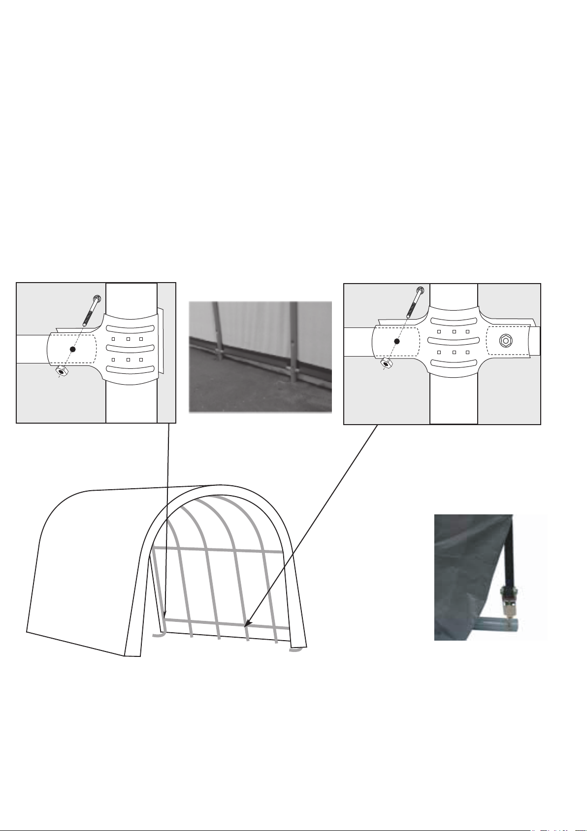
STEP 7 SECURING YOUR COVER
Pull the cover over the frame. The welded in webbing should be at the front and back of the building. Also note that the
pocket with cutouts, running along the sides of the cover should be on the inside and near the ground. Insert the "S" hook
from the ratchets into the hole in the leg of the frame. Next, insert the webbing into the spindle of the ratchet and tighten
ratchet until the webbing overlaps itself, do not tighten all the way yet. Check to be sure the cover still has an even overhang
on the front and rear, adjust as necessary. Once the cover is even, finish tightening the ratchets, alternating from corner to
corner to ensure the cover stays even.
After the cover is tight end to end, remove the cross rails and connectors on one side of the frame and place them into
the pockets between the cutouts. Attach the crossrails using the 3-way and 4-way cover rail clamps around the uprights and
loosey fasten with the 1/4" x 1 5/8" bolts and 1/4" nuts. Check that the rails are evenly spaced above the ground on both
sides. Push down on the connectors one at a time to tension the cover and tighten the bolts to hold tightly.
Warning:
Do not leave a partially or fully covered unit without being fully anchored. Serious injury to persons or property
could result.
Fig.9
10115
1010
clamps
10112
corner leg
Fig. 8
Fig.10
10115
1010
Outside Corner View
* The ratchets
should be checked
monthly to make sure
the cover is tight.
clamps
10111
middle leg
Fig. 11
Fig. 12
Page 4
Page 5

STEP 8
Find the open side of the protective boot and open it.
Insert the foot of the corner leg into the protective boot.
When the foot is all the way in the boot insert the top edge
of the boot into the hem of the cover (Fig 13).
When complete secure the Velcro on the open side of the boot to
close the boot.
Fig. 13
Page 5
 Loading...