

Page 1
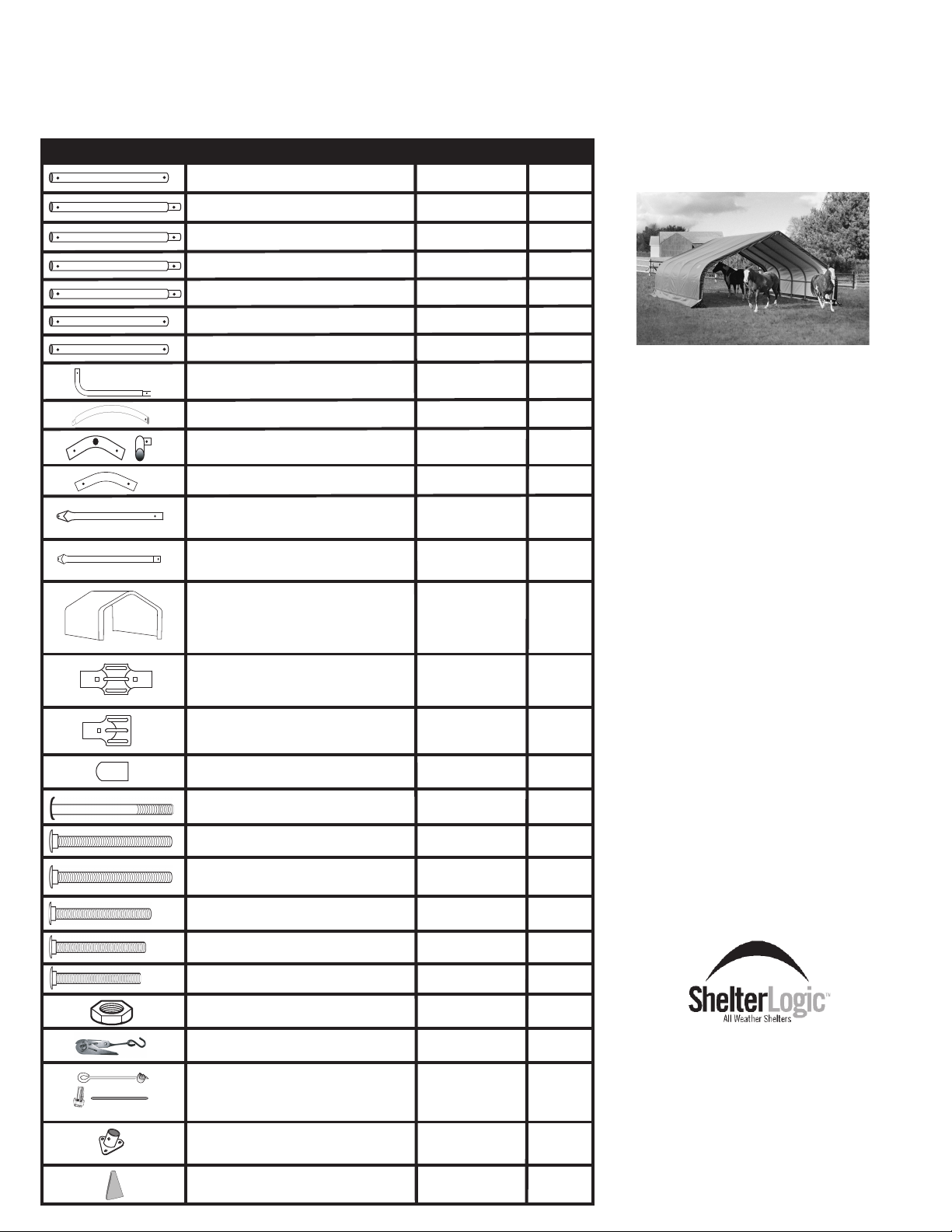
22x20x10 Peak Style
Complete Garage/Shelter Includes: #107133(Basic Frame) ,
#117134(Cover Kit)
Model #
58432
Please read instructions completely before assembly
Description Part # Qty.
Cross Rail Plain Ends
Extension 59.4"L 24
Straight Leg Tube
Cross Rail Swedged
Cross Rail Swedged 48 1/2"L 11103
Cross Rail Plain End 46.6"L
Cross Rail Plain End 48.5"L
Corner Upright Leg
Side Bend Tube 11013 12
End Top Bend 11136 2
Middle Top Bend 11135 4
Wind Brace 30"L 11095
Wind Brace 54.2"L 11093 4
All-Weather Cover 1A7134 1
4-Way Cover Rail Clamp
3-Way Cover Rail Clamp
Bolt Cap
5/16"x 4" Round Head Bolt
Description Part # Qty.
50 1/2"L
45"L
38"L
11105
11068
11019
11102
11101
11104
11016 4
11107
11106 8
11150 24
11133 4
10
8
11
1
1
2
4
16
BASIC HAND TOOLS
REQUIRED FOR ASSEMBLY:
• Adjustable Wrench
• Rubber Mallet
ATTENTION:
BOLTS ARE NOT
NEEDED OR
INCLUDED FOR EVERY
CONNECTION BUT
MAY BE
PURCHASED BY CALLING
THE NUMBER BELOW.
FOR MISSING OR
REPLACEMENT PARTS
OR QUESTIONS
PLEASE CONTACT
5/16"x 4" Bolt
5/16"x 4 1/2" Bolt
5/16"x 2 3/4" Bolt
5/16"x 2 1/4" Bolt
5/16"x 2" Bolt
5/16" Nuts
Ratchet
Temporary 30"Auger Anchors
Cable - 1" Lengths
Cable Clamps
Base Feet
Protective Corner Boots
11132 8
11134 4
11131 60
11130 20
648 6
690
10040
822
11270 8
800196
102
CUSTOMER SERVICE:
1.800.524.9970
8
6
4
150 Callendar Road
Watertown, CT 06795
Page 1
05-58432-0A 07/09/07
Page 2
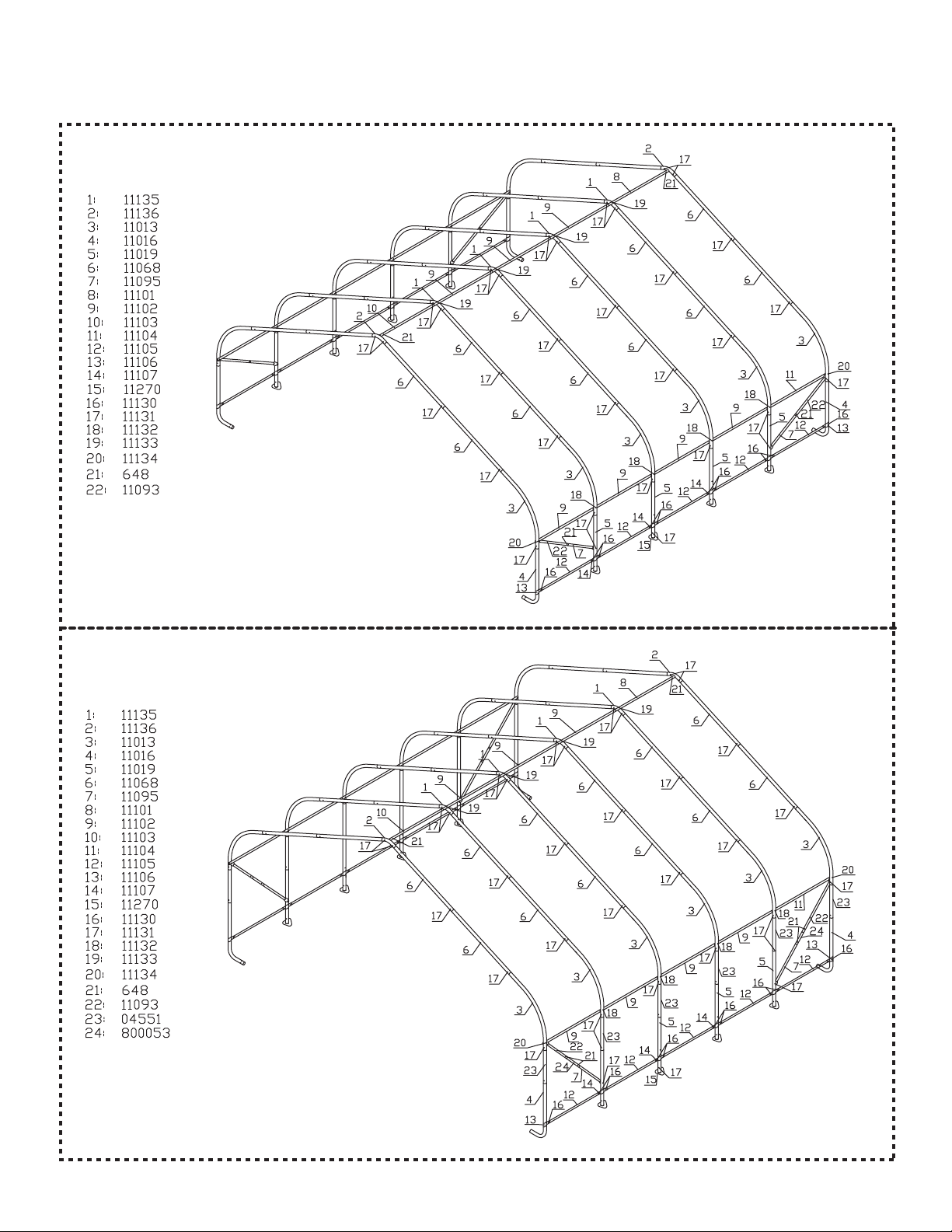
Frame Assembly Overview
22 x 20 x 10 Frame
22 x 20 x 12 Frame
Page 2
05-58432-0A 07/09/07
Page 3
Basic Frame Assembly
STEP 1
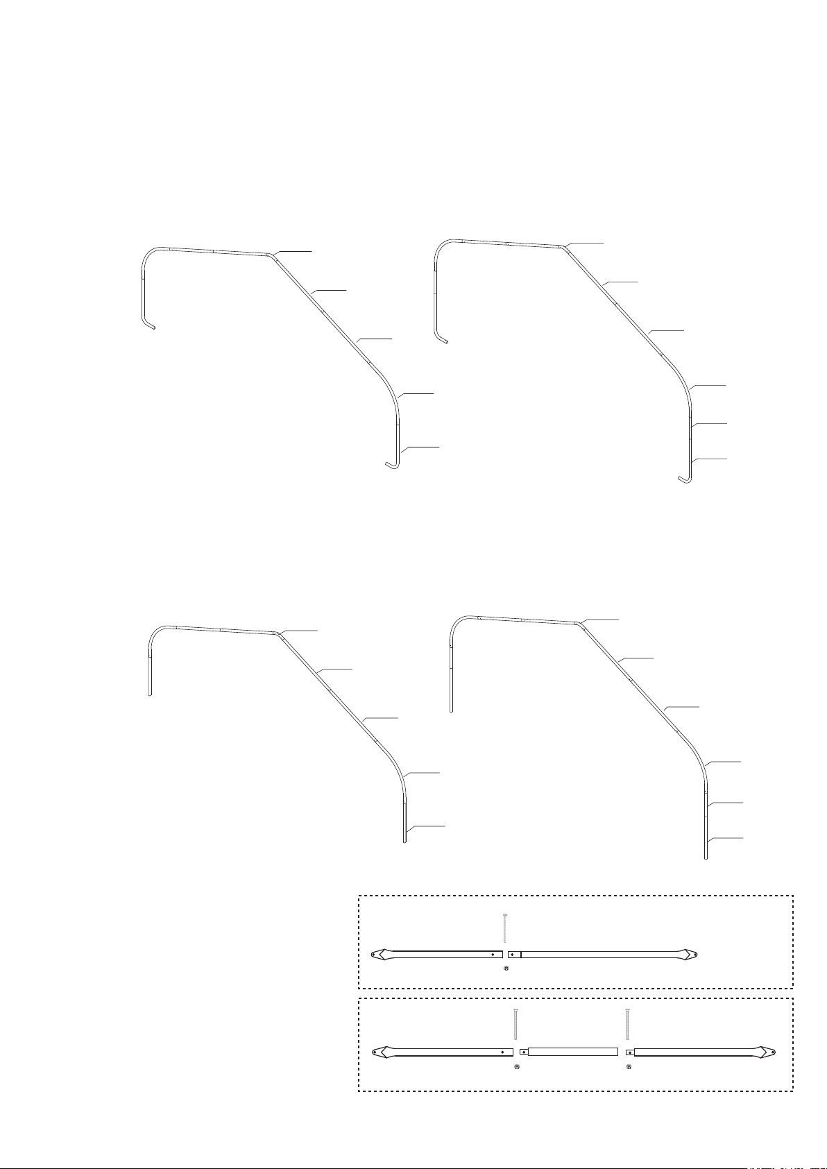
Fit together an end rib using the following parts, (Fig.1) (1) #11136 3-Way Top Connector, (4) #11068 Swedged Rafter Pole, (2)
#11013 Side Bend Tube and (2) #11016 Bend Corner Leg. Using (8) 11131 5/16 X 2 3/4" bolts and (8) 690 5/16" nuts
securely fasten the joints of all parts. Lay this rib on the ground at the rear of your shelters designated location. For a 12'
tall building be sure to include the two foot extension pipe (4551).
NOTE: Be sure that all of the heads of the bolts are facing toward the outside of the rib.
11136
11068
11068
11013
4551
Fig.1
11136
Use 1113 1
5/16" x 2 3/4"
Bolts
11068
11068
Use 1113 1
5/16" x 2 3/4"
Bolts
11013
10' Tall Frame 12' Tall Frame
11016
11016
STEP 2
Fit together the first middle rib using the following parts, (Fig.1) (1) #11135 Top Bend Tube, (4) #11068 Swedged Rafter Pole, (2)
#11013 Side Bend Tube and (2) #11019 Swedged Upright Tube. Using (8) #11131 5/16 X 2 3/4" bolts and (8) #690 5/16"
nuts. Securely fasten the joints of all parts. Lay this rib on the ground near the first end rib. For a 12' tall building be sure
to include the two foot extension pipe (4551).
Fig.2
11135
11068
11135
11068
Use 1113 1
5/16" x 2 3/4"
Bolts
10' Tall Frame 12' Tall Frame
STEP 3
Assemble the wind braces as shown in the
illustrations (Fig.3 & Fig.4).
Fig.3
Fig.4
11068
11013
11019
For Basic Frame
#11095
For 12' Tall Building
#11095
Use 1113 1
5/16" x 2 3/4"
Bolts
#648
#690
#648
#800053
#690
11068
11013
4551
11019
#11093
#648
#11093
#690
Page 3
Page 4

STEP 4
With help stand the first end rib vertically and lean against a permanent structure such as a tree or a fence (Fig.5). Attach the
plain end of a #11102 horizontal tube and a wind brace assembly to the first rib using a #11134 5/16 X 4 1/2" bolt and
a #690 5/16" nut on the INSIDE of the bow, on each side bend just above the joint of the side bend/extension (Fig.6). Repeat
the same steps on opposite side.
Fig.5 Fig.6
11102
11013
11134 Bolt
Wind Brace
11016
11106
11107
11105
STEP 5
Place (2) #11106 3-Way Clamps around #11016 Bent Leg. Insert #11105 Cover Rail into the clamp and attach using a
#648 5/16 X 2" bolt and #690 5/16" nut. Position the clamp about five inches above the ground and tighten the nut
and bolt finger tight (Fig.7). Repeat the same steps on opposite side.
11130
clamps
11106
Fig.7
690
corner leg
STEP 6
With help position the first middle rib about four feet from the first end rib. While one person holds the middle rib vertical
the other person should raise the previously installed #11102 cross rail and place another #11102 over each of the previous.
Raise the two rails so they are horizontal and attach to the middle cross rail using a #11132 5/16 X 4" bolt and a #690
5/16" nut. Attach a #11107 4-Way Clamp to the end of the (2) cover rail tubes using a #648 5/16 X 2" bolt and a #690 5/16"
nut. (Fig.8) Place the clamp around the middle leg and insert a #11105 cover rail into the opposite side of the clamp and attach
with a #648 5/16 X 2" bolt and a #690 5/16" nut. Position the clamp about five inches above the ground and tighten
finger tight. Raise the cross brace to the middle rib and attach it to the rib using a #11131 5/16 X 2 3/4" bolt and a #690
5/16" nut, (Fig.9) Repeat these steps for the opposite side.
Repeat the cross rail installation for the remaining middle legs.
11130
clamps
11107
Fig.8 Fig.9
690
middle leg
Page 4
11013
11134 Bolt
11016
11132 Bolt
11102
11019
11131 Bolt
11107
11105
11106
Page 5

STEP 7
Install the other end rib as you had installed all the middle ribs only use #11104 crossrails and attach the sliding crossrail
using the remaining 3-way coverrail clamps.
Note: The final windbrace assemblies should be installed as shown. Be sure the upper of the windbraces are
installed between the rib and crossrail
Step 8 Installing T
Install the top cross rail assembly starting with #11103 Cross
Rail Swedged 48 1/2"L inserted into the End 2-Way Connector.
Secure with a #648 5/16 X 2" bolt and #690 nut. Place the
plain end of a #11103 Cross Rail Swedged over the end and
put the joint on the top of the middle rib. Secure with a #11133
5/16 X 4" Round Head Bolt and #690 Nut. Continue adding
#11102 Cross Rails and finish with the #11101 Cross Rail Plain
End inserted into the last end 3-way connector and secure with
a #648 5/16 X 2" bolt and #690 nut.
NOTE: Use the special Round Head Bolts for securing the
top rail to the middle ribs only!!!
op Rail
(Fig.10)
Install the Top Rail
Over all Middle Ribs
Fig.10
Step 9 SQUARING THE SHELTER
Check that the shelter's width is correct from the outside to
outside of the uprights at ground level. Check also that the
shelter is square by measuring diagonally from corner to
corner at ground level. (Fig.11)
The two measurements must be within 2 inches of each
other.
STEP 10 ATTACHING & SECURING BASE FEET
Depending on the model you have purchased, your base feet will either fit
onto the outside of the leg poles, or slide inside the leg poles. After installing
Base Feet Plates onto bottom of Middle leg Poles, be sure to line up the
pre-drilled hole in the leg with the pre-drilled hole in the base foot. Insert
5/16" x 2 3/4" bolts all the way through leg and foot, to other side, secure with
nuts. (Fig.12)
22'
Fig.11
Page 5
Fig.12
Page 6

STEP 11 INSTALLING AUGER ANCHORS
Using a 3/4" pipe or steel rod, (a car tire iron works also) placed
through the eyelet on the auger, screw it into the ground. Start at
the four corners of the unit and space the remainder out evenly.
Be sure to screw the anchor in fully (the eyelet should be a level
where it can be securely attached to the frame. Wrap the cable
provided through the eyelet of the anchor and around the frame.
Secure the cable with the clamp(s) provided. (Fig.13)
WARNING:
DO NOT INSTALL THE END PANELS OR COVER ON THE
SHELTER UNTIL IT HAS BEEN PROPERLY ANCHORED.
Fig.13
Step 12 Securing Your Cover
Pull the cover over the frame. The welded in webbing should be on the front and back of the building. Also note that
the pocket with the cutouts running along the sides of the cover should be on the inside and near the ground. Install
the "S" hooks from the ratchet assemblies into the legs of the shelter. Pull the webbing carefully to remove slack from
the cover. Be careful not to pull the webbing through the opposite side. Insert the webbing into the spindle of the ratchet
and pull tight. Wind the ratchet enough so that the webbing overlaps itself. Repeat the process of tightening one side
and then the other until the cover is as tight as possible and still even on the rib.
NOTE: The logos should be horizontal and about 5' above the ground on the outside of the garage.
After the cover is tight end to end remove the 45" cover rails. Insert the cover rails into the pockets of the cover.
Re-clamp the rails to the ribs with the 3-way (Fig.14) and 4- way (Fig.15) clamps. Check that the rails are evenly
spaced above the ground on both sides. (Fig.16) Push down the connectors, one at a time, to tension the cover.
Tighten the bolts to hold tightly.
Fig.14
11130
690
clamps
11106
corner leg
Fig.15
11130
690
clamps
11107
middle leg
Outside Corner View
* The ratchets
should be checked
monthly to make sure
the cover is tight.
(Fig.17)
Fig. 16
Fig. 17
Page 6
Page 7

STEP 13 ATTACHING THE
PROTECTIVE BOOTS
Find the open side of the Protective Boot and open it.
Insert the foot of the Corner Leg into the Protective Boot.
When the foot is all the way in the boot insert the top edge
of the boot into the hem of the cover (Fig 18).
When complete, secure the hook & loop fastener on the
open side of the boot to close the boot.
Fig. 18
WARNING
Prior to installation, consult with all local and municipal codes regarding the installation of temporary
shelters. Choose the location of your shelter carefully. Check for overhead utility lines, tree branches or
other structures. Do NOT install near roof lines or other structures that could shed snow, ice, or excessive
run-off onto your shelter. Do NOT hang objects from the roof structure or support cables. Do NOT smoke
our use open flame devices in or around the shelter. Do NOT store flammable liquids (gasoline, kerosene,
propane, barbeque grills, fire pits, deep fryers or smokers inside the shelter. Do NOT use hard edged tools
or instruments like rakes or shovels to remove snow. This could result in punctures in the cover.
CAUTION
This product is classified as a temporary fabric shelter and is intended to protect what is stored in it
against basic environmental elements, including the effects of sun, rain, tree sap, bird and animal
excrement and light snow. It is NOT designed to hold the loads from high winds, heavy snow or ice
storms. Proper anchoring is the responsibility of the consumer. Please read and understand the
installation details and warnings prior to final and permanent installatioin. If you have any questions,
call the customer service number listed on Page 1. Any shelter that is not anchored securely and properly
has the potential to fly away. ShelterLogic cannot be responsible for any shelter that blows away. NOTE:
Your shelter’s cover can be quickly removed and stored prior to severe weather conditions. If strong
winds or severe weather is forecast in your area, we recommend that you remove the cover.
CARE & CLEANING
A tight cover will ensure longer life and performance. Inspect and retighten the ratchet tie-downs monthly
as needed. Always maintain a tight cover. Loose fabric can accelerate deterioration of the cover.
Immediately remove any accumulated snow or ice from the roof structure with a broom, mop or other
soft sided instrument. Do NOT use “protect and shine” or harsh or abrasive products to clean the fabric
cover. Mild soap and water is recommended to clean the fabric cover of your shelter.
Page 7
Page 8

150 Callender Road
Watertown, CT 06795
For Replacement Parts or Help with assembly, Please call:
Customer Service:
1-800-524-9970
8am-7pm
Mon-Sat EST
 Loading...