

Page 1
24'x 40' ULTRA MAX PEAK CANOPY
#27273
Please read instructions completely before asse
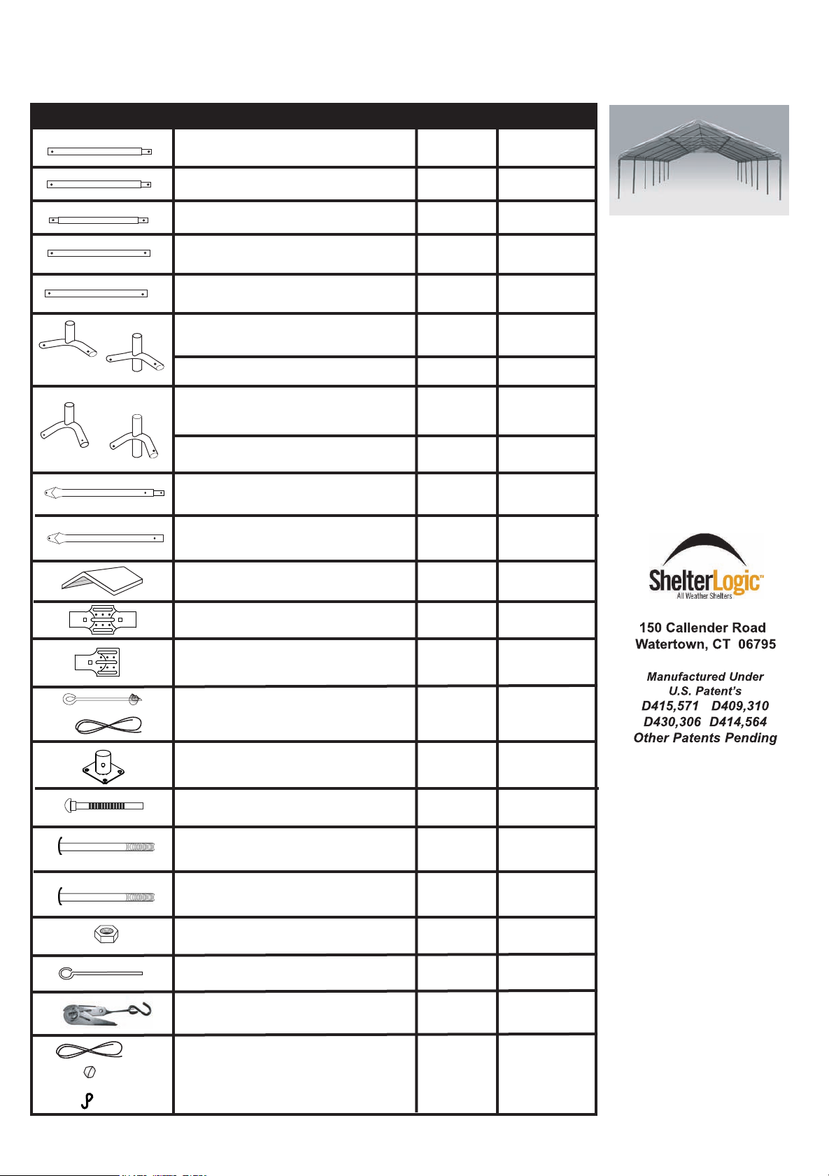
Description Qty. Part #
Support Tube 72 3/8"
Common Tube 72 3/8"
Oblique Tube 72 3/8"
Cross Rail 77 1/8"
Pocket Pipe 77 3/8"
(Top Bend, shallow bend)
3-Way Frame Connectors
4-Way Frame Connectors
(Side Bend, sharp bend)
3-Way Frame Connectors
4-Way Frame Connectors
Wind Brace (Swedged Ends)
4
24
14
18
12
2
5
4
10
800216
800095
800096
800098
800230
800091
800093
800092
800094
8001047
FOR MISSING,
REPLACEMENT PARTS
PLEASE CONTACT
CONSUMER SUPPORT
mbly
Model : 24'x40'
OR
QUESTIONS
1-800-524-9970
Wind Brace (Flat Ends)
All-Weather Cover
4-Way Cover Rail Clamp
3-Way Cover Rail Clamp
Temporay 15 ”Auger Anchor s
Ropes
Base Feet
5/16"x 2 1/4" Bolts
5/16" x 2" Round Head Bolts
5/16" x 3" Round Head Bolts
Nuts 5/16"
Anchor
Ratchet
White Rope
Rope bead
"S" Hook
1
20
8
18
18
14
24
43
70
137
56
4
2
4
4
8001037
800235
800221
800220
10014
10437
800105
11130
800217
800218
00690
10431
10040
800233
10465
800225
WARNING!
Use CAUTION when assembling this unit. Be aware of poles
over your head during assembly
that may not be secured, and
could fall and cause injury.
PAGE 1
05-27273-0A
01/10/07
Page 2
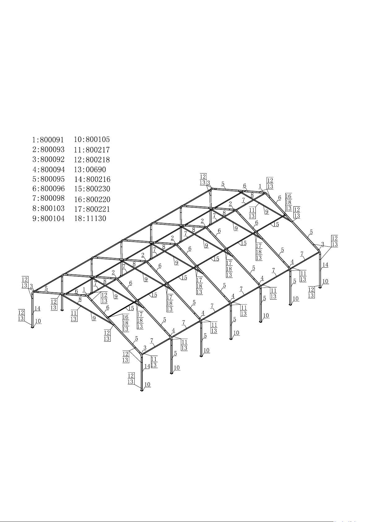
Frame Assembly Overview
PAGE 2
Page 3

Basic Frame Assembly
STEP 1
Assemble the wind brace set as shown in the
illustrations.
STEP 2
Step 2A
Fit together the end rib using the following parts
(1) #800091 3-Way Top Connectors
(2) #800096 Rafter Poles
(2) #800095 Common Tubes
(2) #800092 3-Way Side Connectors
(1) Wind Brace set
Step 2B
Fit together the middle rib using the following parts
(1) #800093 4-Way Top Connectors
(2) #800096 Rafter Poles
(2) #800095 Common Tubes
(2) #800094 4-Way Side Connectors
(1) Wind Brace set
Using (6) #800218 (5/16" x3" Bolts) and (6) Nuts securely
fasten these tubes. Lay these ribs on the ground at the rear
of your shelters designated location.
NOTE: Be sure that all of the heads of the bolts are
facing toward the outside of the rib.
Repeat step 2A/2B for all the other ribs.
Fig. 1
Fig. 2A
800092
800094
800095
Fig. 2B
#800103
800095
#800217
#800104
#00690
800096
#800218(5/16"x3"Bolt)
800091
2 End Ribs
800096
#800218(5/16"x3"Bolt)
800093
Middle Ribs
Wind brace
Wind brace
STEP 3
800098
Using #800098 Cross Rails, #800217
(5/16" x 2" Bolts) and Nuts to connect
these ribs.
STEP 4
Assemble (2) #800216 Corner Support Tubes and (4) # 800095 middle support tube as shown in Fig. 4A and set aside.
Assemble other side Support Tubes as shown in Fig. 4B and connect the middle support tubes with #800218 (5/16" x 3"
Bolts) and nuts. Repeat this step at opposite side.
Note: #800218 Bolts are required for middle support tube connections. Bolts are not inserted to the corner legs
(#800216) at this step.
Fig. 4BFig. 4A
800216
800216
800095
800095
PAGE 3
Page 4

STEP 5
Rope
Depending on the model you have purchased, your
base feet will either fit onto the outside of the leg poles,
or slide inside the leg poles. After installing Base Feet
Plates onto bottom of Support leg Poles, be sure to
line up the predrilled hole in the leg with the predrilled
hole in the base foot. Insert 5/16" x 3" bolts all the way
through leg and foot to other side, secure with nuts.
Note: Don't insert the bolt to the corner legs at this step.
Locate a suitable location to place 4 anchors as shown
in the illustration into each of the base feet until
the round end of the anchor touches the base feet.
Fig. 5A
Fig. 5B
STEP 6
Fig.6
Fig.6A
Tie a loop into the end of the
rope. Feed the loop over the
top of the rafter pole and feed
the other end of the rope through
the loop and run the rope down
the leg at least 12" and wrap
the rope around the leg and
feed the loose end over the
rope (Fig.6A).
Take the loose end of the robe
and secure it to the auger anchor already secured in the ground
(Fig.6B).Repeat these steps for the
remaining legs on the canopy.
Fig.6B
STEP 7
Position the cover on the side of the frame with the side with the grommets parallel to the frame and facing down.
Go to the opposite side of the frame and throw at least three ropes over the frame (evenly spaced along the length
of the frame). Tie the ropes to the grommets on the cover and use the rope to pull the cover over the frame (the
more people and ropes you have to pull the cover over the easier it is to do). Position the cover so that the valance
is even front to back and side to side.
Slide the pocket pipes into the cover pockets between the cutouts. Attach the pocket pipes to the frame using the
3 & 4 way clamps (800220 & 800221) and the 5/16 X 2 #11130 bolts and nuts. Check that the pocket pipes are
evenly spaced on both sides of the top pipe. Slide the pocket pipe down the length of the rafters to tighten the top
section of the cover. When the cover is pulled tight secure the bolts and nuts in the sliding clamps to hold them in
place.
11130
Fig.7A
Fig.7
clamps
800221
Pocket Pipe
PAGE 4
Fig.7B
690
11130
690
middle
clamps
800220
corner
Page 5

Slide the rope through the grommets and around
the side extention tubes at both sides shown
in Fig.7C, Fig.7D & Fig.7E. Insert the 'S' hook to the
corner leg tube, then 'twist' the leg to tight the rope.
After tighting the rope, secure the (4) corner leg tubes
#800216 to the corner connectors and feet plates with
#800218 (5/16" x 3" Bolts) and nuts.
STEP 8
Use the (4) Ratchets as shown in Fig.8A.
Adjust the cover so there is equal overhang
on the front and rear. With the webbing and
ratchets pull the cover snug but not tight.
When all of the half clamps and rope are
secured tight finish tightening the (4) Ratchets
to make final adjustment to the cover.
Fig.7C
Fig.8A
Fig.7D
Fig.7E
Fig.8B
PAGE 5
 Loading...