

Page 1
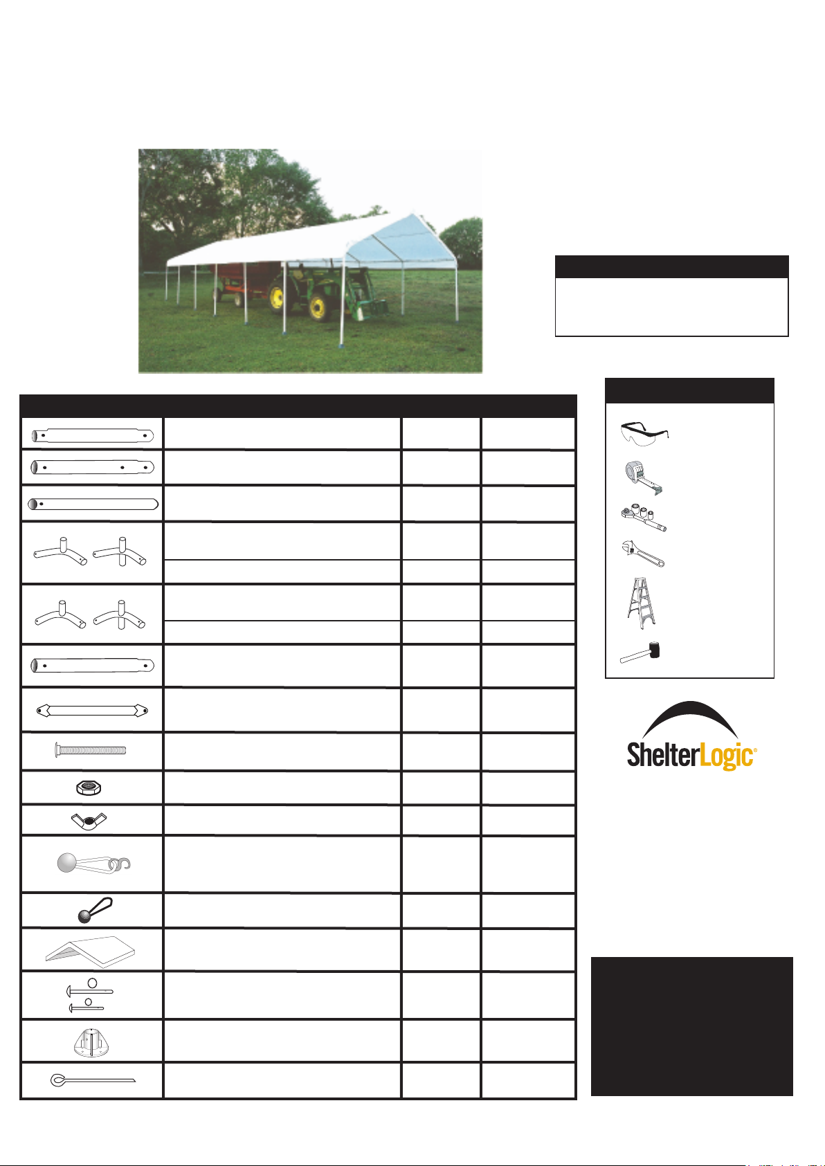
18X40
Model #26764
Description Qty. Part #
PREMIUM INDUSTRIAL CANOPY
orPlease read instructions completely bef e assembly
Before You Start
• 2 or more persons recommended
to assemble
• Estimated assembly time = 2 hours
Recommended Tools
71.4" Swedged Rafter Poles
76" Swedged Leg Poles
77.4" Cross Poles
(Top Bend, shallow bend)
3-Way Frame Connectors
4-Way Frame Connectors 10048
(Side Bend, sharp bend)
3-Way Frame Connectors
4-Way Frame Connectors
38.5" Swedged Rafter Poles
Truss
Bolts 1/4" x 2 1/2"
Nuts 1/4"
Wing Nuts
Twist Tite
TM
(bungee & S hook)
Set
Bungee Cords
All-Weather Cover
Long Pins w/rings 1/4" x 2 7/8"
Short Pins w/rings 1/4" x 2 1/4"
Feet Plates
Anchors
14
14
18
2
5
4
10
14
7
28
14
14
4
48
1
14
10
14
14
802105
10043
10044
10046
10045
10047
802104
802103
10017
1010
7000
10056
10066
10179
10052
10051
10050
10431
Safety Glasses
Tape Measure
Ratchet with
7/16
"
Adjustable
wrench
Ladder
Rubber Mallet
800.524.9970
www.shelterlogic.com
150 Callender Road
Watertown, CT 06795
Manufactured Under
U.S. Patents
D415,571 D409,310
D430,306 D414,564
Other Patents Pending
ATTENTION: PINS
Long Pins secure feet plates to legs.
Short Pins secure legs to side bends.
Pins are for legs and feet
only , and are
for any other part of the
frame.
NOT
needed
PAGE 1
05-26764-0C
11/01/07
Page 2
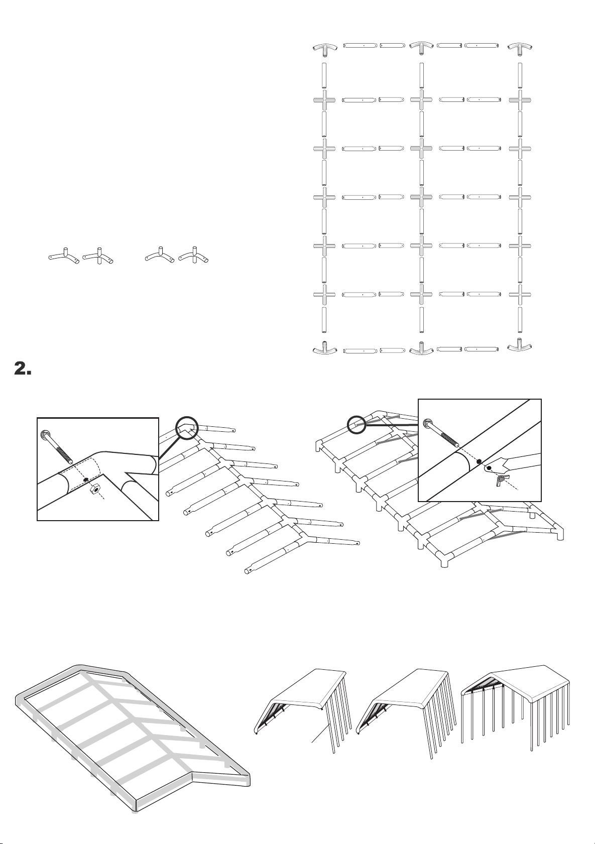
1.
01010
10017
10017
7000
Fig. 2A
802103
Frame Assembly
10045
802105 802105802104 802104
10046
10045
Assembly is easiest if you layout all parts as
shown. There are (14) #802105 Rafter Poles ,
they are swedged on both ends. (14) #802104
Rafter Poles, they are swedged end. The (18)
#10044 Cross Poles do not have swedged
ends. It is very important that you determine
which of the 3 & 4 way connectors are meant
for the sides and which are for the crest.
10046 10048
Top Crest Connectors
(shallow bend)
10045 10047
Side Bend Connectors
(sharp bend)
10044 10044 10044
10047
10047 10047
10047 10047
10047 10047
10047 10047
10045
802105 802105802104 802104
10044 10044 10044
802105 802105802104 802104
10044 10044 10044
802105 802105802104 802104
10044 10044 10044
802105 802105802104 802104
10044 10044 10044
802105 802105802104 802104
10044 10044 10044
802105 802105802104 802104
10048
10048
10048
10048
10048
10046
10047
10045
Assemble Roof
Start with center, Fig. 1, using layout shown in diagram above. Bolt roof
assembly together as shown in Fig. 1A. Assemble each side of the roof as shown in Fig. 2. Install #802103 truss
as shown in Fig. 2A.
Fig. 1A
Note: Install all carriage bolts
with nut toward center of frame.
3. Place Cover
Place cover over frame so that the
grommeted portion is face down,
this allows the valance to wrap
around and cover the frame eaves.
Fig. 1
4. Attaching Legs
Insert #10043 Leg Poles on one side of the frame, swedged
end up, then the end legs on that same side. Repeat for the
other side. Now you can secure the legs to the side bend
connectors and secure the cover with bungee cords.
Fig. 2
10043
PAGE 2
Page 3

5. Securing Legs
6. Securing Cover
Short Pins are used to secure legs to
side bend connectors.
7. Twist Tite
To get your cover to fit
7.1
snugly over the frame, "twist"
each corner leg pole equally
until the cover becomes very
tight. (picture A). Make sure
to line up the hole in the top
of the leg with the hole in the
corner side bends.
TM
Working inside, under-neath the unit, begin with the corners.
Insert the cord of the bungee-ball through the grommet and
around the Cross Pole, then around the ball. By doing
this from the inside it will hide the bungee-ball and give a cleaner look. When all 4 corners are secured, work from side to
side to get an even fit.
B
Picture B
7.2
in place, wrap the bungee cord
around the cross rail, insert "S"
hook into lined up hole of leg
pole and 3 way connector. Do
this for each corner.
To keep the leg
8. Attaching &
Securing base
Feet
Insert Base Feet Plates onto
bottom of legs, be sure to line
up the pre-drilled hole in the leg
with the pre-drilled hole in the
base foot. Insert long pins all
the way through leg and foot,
to other side, secure with ring.
PAGE 3
Page 4

9. Anchoring
Locate a suitable location to place one anchors
as shown in the illustration into each of the base
feet until the round end of the anchor touches the
base feet.
PAGE 4
 Loading...