

Page 1
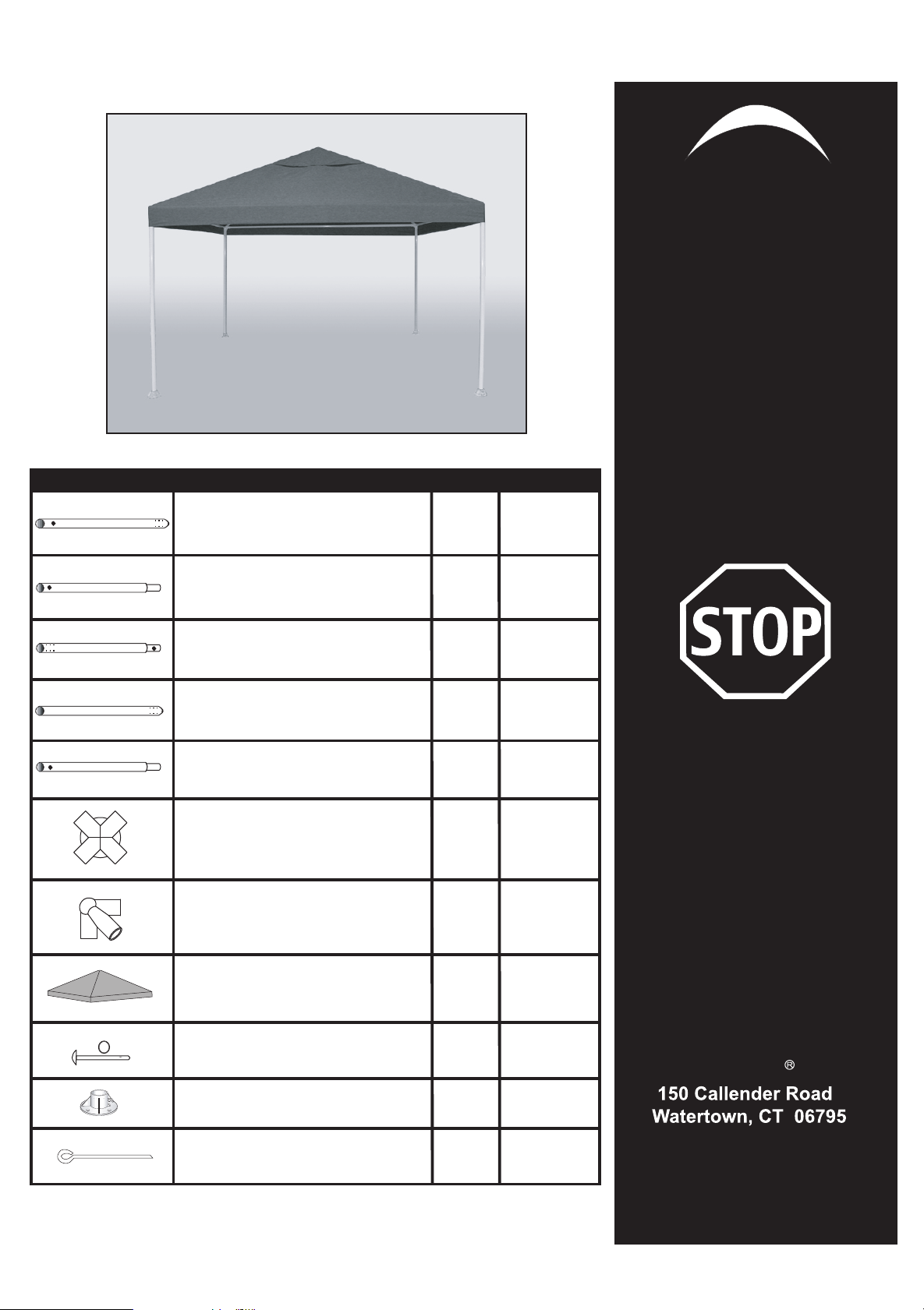
The Canopy
Factory
ShelterLogic
Model #25793
10' x 10'
Celebration Canopy
Installation
Description Qty Part #
Rafter Tube 44.6"
Rafter Tube 44.6"
Cross Rails 31.7"
Upright Tube 42.4"
Upright Tube 42.4"
4-Way Top Connectors
3-Way Top Connectors
.
8 10386
8 10387
4
4
4
1
4
10390
10391
10392
10585
10385
Instructions
Please read instructions
COMPLETELY before assembly.
DO NOT RETURN
PRODUCT TO
THE STORE
Missing Parts,
Need Replacements,or
Help with Assembly
Cover
Pins w/rings
Base Feet
Anchors
Please Contact
1
10393
Customer Service:
1-800-524-9970
4
4
8
10052
10050
10431
ShelterLogic ,LLC
www.shelterlogic.com
05-25793-0C
Pg.1
10/08/08
Page 2
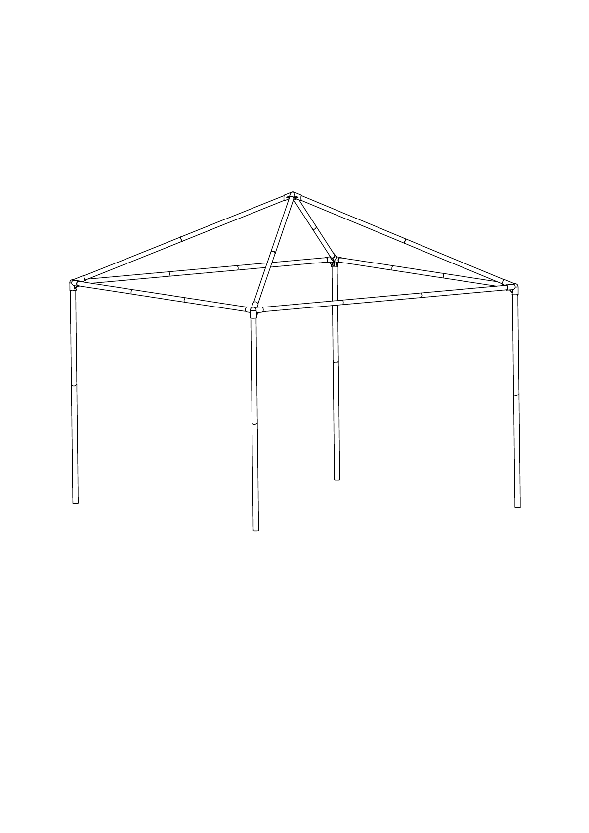
Frame Assembly Overview
10585
10387
10386
10385
10386
10390
10387
10391
10392
CARE & CLEANING INFORMATION
DO NOT
DO NOT
following exposure to high winds or heavy rain.
IMPORTANT:PLEASE READ CAREFULLY:
sible for damage caused by the canopy or to the canopy. We suggest you contact your insurance carrier for information just as you would for any other outside structure.
This is a Temporary Structure and is not recommended as a permanent structure.
Improper Anchoring, Strong Winds, Snow or Ice:
circumstances.
canopy that is not anchored securely or properly will fly away. We will not be responsible for any canopy that blows away. proper anchoring is your responsibility. We offer several anchoring kits,
call customer service for more information or to place an order. Your canopy's cover can be quickly removed if needed when you know that a strong or severe weather front is approaching.
expose top or walls to open fire or flame.
use harsh abrasives, bleach or cleansers. Cover and walls can be easily cleaned with mild soap and water. Periodically check stakes or anchors to ensure stability of unit, especially
Canopies are designed to offer protection from damage caused by sun, light rain, tree sap, birds, and are not designed to hold the loads that accompany snow or ice. Any
DO NOT
NOT
meant to hold snow load, brush snow off top with a broom or mop.
use barbeque grills or smokers underneath canopy.
ShelterLogic has no control over the elements such as wind, snow or heavy rain, we cannot be respon-
ShelterLogic
does not guarantee these canopies in snow or ice under any
Safety glasses must be worm when securing bunges.
CAUTION! WARNING!
Bungee cords are under extreme tension. Please use caution when applying as they may snap out of your hand and cause injury. The use of safety goggles may help to prevent injury.
Page 2
Page 3

1. Frame Assembly
The part number is stamped on each part.
Assembly rafter tube 10386 to rafter tube 10387, the
connector pins should be facing out, there should be
four assembled tubes when complete.
Depress the assembly buttons at the end of each tube
and assemble the four assembled tubes into top con nector 10585, be sure the buttons click into the holes
in the connector.
Assemble rafter tube 10386 to rafter tube 10390 and
rafter tube10387 the assembly buttons should be fac ing out.
Depress the assembly button at the end of the tubing
and assemble corner connector 10385 into the asse mbled tubing 10386 and 10387. Do this on all four
corners.
10385
10386 10390
10386
10387
10585
10387
2. Attaching Legs
Assembly upright tube 10391 to upright tube10392. Do
this for all four legs.
Lift one end of the assemble top and depress the ass embly button and insert the tube into the three way
corner connector 10385, confirm the assembly button
clicks into the three way connector 10385.
After installing two of the upright tubes, lift the other
side of the assemble top and install the last two upright
tubes. Your canopy will be sitting on all four uprights.
Fig. 1
10391
10392
Fig. 2A
Page 3
Fig. 2B
Page 4

3. Securing Cover
Unpackaged the cover and place the bright blue side facing up over the assemble canopy frame.
Once the cover is placed over the frame to secure the cover pick up the corner of the cover to expose the elastic
and metal hold down clips. Secure the metal clips to the into the upright tubes holes see figure 4.
Once the cover has been attached in all four corners attach the bungee to the tube see figure 5.
4. Base Feet
Insert Base Feet Plates onto bottom of legs,
be sure to line up the pre-drilled hole in the
leg with the pre-drilled hole in the base foot.
Insert PIN all the way through leg and foot,
to other side, secure with ring.
Fig. 4
Fig. 3
Fig. 5
5. Anchors
Locate a suitable location to place two anchors
as shown in the illustration into each of the base
feet until the round end of the anchor couches the
base feet.
Fig. 6
Fig. 7
Page 4
 Loading...