


Installation and
Operation Manual
SMO34HP-2, SMO38HP-2
SMO14HP-2, SM10HP-2
Previously Designated:
HF25-2, HF37-2, HF15-2, HF10-2
SMO HIGH PERFORMANCE OVENS
220 - 240 Voltage

SMO10HP-2
SMO High Performance Ovens 220 - 240 Voltage
Large Capacity
Installation and Operation Manual
Part number (Manual): 4861705
Revision: December 14, 2015
These ovens do not plug into a wall using a conventional plug. These ovens require
permanent connect wiring (also known as hardwiring).
Pictured on front cover, left to right: SMO34HP-2, SMO38HP-2, SMO14HP-2
These units are TÜV CUE listed as forced air ovens for professional, industrial, or educational use
where the preparation or testing of materials is done at an ambient air pressure range of 22.14 –
31.3 inHg (75 – 106 kPa) and no flammable, volatile, or combustible materials are being heated.
The units have been tested to the following requirements:
CAN/CSA C22.2 No. 61010-1:2012
CAN/CSA C22.2 No. 61010-2-010:2004 Reaffirmed: 2014-07
UL 61010-1:2012-05
UL 61010A-2-010:2002-03
EN 61010-1:2010
EN 61010-2-010:2014
Supplemented by: UL 61010-2-010:2015
2 | P a g e

TABLE OF CONTENTS
INTRODUCTION ........................................................................................................................................... 4
General Safety Considerations ................................................................................................................. 4
Engineering Improvements ....................................................................................................................... 5
Contacting Assistance ............................................................................................................................... 5
RECEIVING YOUR OVEN ............................................................................................................................ 6
Inspecting the Shipment ............................................................................................................................ 6
Orientation Photos..................................................................................................................................... 7
Recording Data Plate Information ........................................................................................................... 11
Temperature Reference Sensor Device ................................................................................................. 11
INSTALLATION .......................................................................................................................................... 12
Required Ambient Conditions ................................................................................................................. 12
Location Considerations .......................................................................................................................... 12
Power Source Requirements .................................................................................................................. 13
Power Feed Wiring .................................................................................................................................. 14
Lifting and Handling ................................................................................................................................ 14
Leveling ................................................................................................................................................... 14
Install the Oven ....................................................................................................................................... 15
Initial Cleaning ......................................................................................................................................... 15
Shelving Installation ................................................................................................................................ 15
GRAPHIC SYMBOLS ................................................................................................................................. 16
CONTROL PANEL OVERVIEW ................................................................................................................. 18
OPERATION ............................................................................................................................................... 21
Operating Precautions ............................................................................................................................ 21
Preparing the Oven for Use .................................................................................................................... 24
Prepare for First Use Burn-In .................................................................................................................. 24
Set the Temperature Set Point ................................................................................................................ 25
First Use Burn In ..................................................................................................................................... 26
Temperature Accuracy Verification ......................................................................................................... 28
Set the Over Temperature Limit .............................................................................................................. 30
OTL Activation During Normal Operations .............................................................................................. 31
Programming a Heating Profile ............................................................................................................... 31
Positive Venting of Exhaust .................................................................................................................... 32
USER MAINTENANCE ............................................................................................................................... 34
Cleaning and Disinfecting ....................................................................................................................... 34
Electrical Components ............................................................................................................................ 35
Door Gaskets and Chamber Integrity...................................................................................................... 35
Calibrate the Temperature display .......................................................................................................... 36
UNIT SPECIFICATIONS ............................................................................................................................. 40
Weight ..................................................................................................................................................... 40
Dimensions .............................................................................................................................................. 40
Capacity .................................................................................................................................................. 41
Shelf Capacity by Weight ........................................................................................................................ 41
Temperature ............................................................................................................................................ 41
Power ...................................................................................................................................................... 41
REPLACEMENT PART LIST ..................................................................................................................... 42
3 | P a g e

INTRODUCTION
Thank you for purchasing a Sheldon Manufacturing SMO forced air, high performance oven. We
know that in today’s competitive marketplace customers have many choices when it comes to
constant temperature equipment. We appreciate you choosing ours. Our continued reputation as a
leading laboratory product manufacturer rests with you. We stand behind our products and will be
here for you if you need us.
These ovens are intended for professional, industrial, and educational applications requiring
horizontal shelf space air flows. The ovens are not designed for use at hazardous or household
locations.
GENERAL SAFETY CONSIDERATIONS
Note: Failure to follow the guidelines and instructions in this manual may create a protection
impairment by disabling or interfering with the unit’s safety features. This can result in injury
or death.
Before you use your oven read this entire manual carefully to understand how to install, operate,
and maintain the oven in a safe manner. Keep this manual available for use by all oven operators.
Ensure that all operators are given appropriate training before the oven begins service.
Your oven and its recommended accessories have been designed and tested to meet strict safety
requirements. For continued safe operation of your oven, always follow basic safety precautions
including:
Follow any local or regional ordinances in your area regarding the use of this unit.
Only use the oven for its intended range of applications.
Use only approved accessories. Do not modify system components. Any alterations or
modifications to your oven may be dangerous and will void your warranty.
Always hardwire the unit power feed to a protective earth-grounded electrical source that
conforms to national and local electrical codes. If the unit is not grounded, parts such as,
knobs and controls may conduct electricity and cause serious injury.
Avoid damaging the power feed. Do not bend it excessively, step on it, place heavy objects
on it. A damaged power feed can easily become a shock or fire hazard. Never use a power
feed after it has been damaged.
Position the equipment so the end-user can quickly and easily disconnect or uncouple the
power feed in the event of an emergency.
Do not attempt to move the unit while in operation or before the unit has cooled.
4 | P a g e

INTRODUCTION (CONTINUED)
ENGINEERING IMPROVEMENTS
Sheldon Manufacturing continually improves all of its products. As a result, engineering changes
and improvements are made from time to time. Therefore, some changes, modifications, and
improvements may not be covered in this manual. If your unit’s operating characteristics or
appearance differs from those described in this manual, please contact your Shel Lab dealer or
customer service representative for assistance.
CONTACTING ASSISTANCE
If you are unable to resolve a technical issue with the oven, please contact Sheldon Technical
Support. Phone hours for Sheldon Technical Support are 6am – 4:30pm Pacific Coast Time (west
coast of the United States, UTC -8).
Please have the following information ready when calling or emailing Technical Support: the model
number and the serial number. These will be found on the unit’s data plate, which is located on
the back of the unit at the top right, next to the power supply as mandated by regulatory
requirement. See page 7.
EMAIL: tech@shellab.com 1-800-322-4897 extension 4, or (503) 640-3000 FAX: (503) 640-1366
Sheldon Manufacturing INC.
P.O. Box 627
Cornelius, OR 97113
5 | P a g e

Model
Shelves
Shelf Slides / Clips
Leveling Feet
SMO10HP-2
3
12 Clips
4
SMO14HP-2
6
24 Clips
4
SMO34HP-2
6
24 Clips
4
SMO38HP-2
12
48 Clips
4
RECEIVING YOUR OVEN
Before leaving the factory, all ovens are packaged in high-quality shipping materials to provide
protection from transportation-related damage. When a unit departs our factory, safe delivery
becomes the responsibility of the carrier. Damage sustained during transit is not covered by the
manufacturing defect warranty.
This makes it important that you inspect your oven for concealed loss or damage to its interior and
exterior when receiving it. If you find any damage to the unit, follow the carrier’s procedure for
claiming damage or loss.
The orientation photos on the immediately following pages may serve as useful references when
inspecting the oven.
Carefully check all packaging before discarding. Save the shipping carton until you are certain that
the unit and its accessories function properly.
INSPECTING THE SHIPMENT
Carefully inspect the shipping carton for damage. Report any damage to the carrier service that
delivered the SMOHP oven. If the carton is not damaged, open the carton and remove the
contents. The unit should come with an Installation and Operation Manual, and a Certificate of
Compliance.
Verify that the correct number of shelves, shelf slides, and leveling feet have been included (see
the following table for quantities).
Included accessories
Carefully check all packaging before discarding. Save the shipping carton until you are certain that
the unit and its accessories function properly.
6 | P a g e
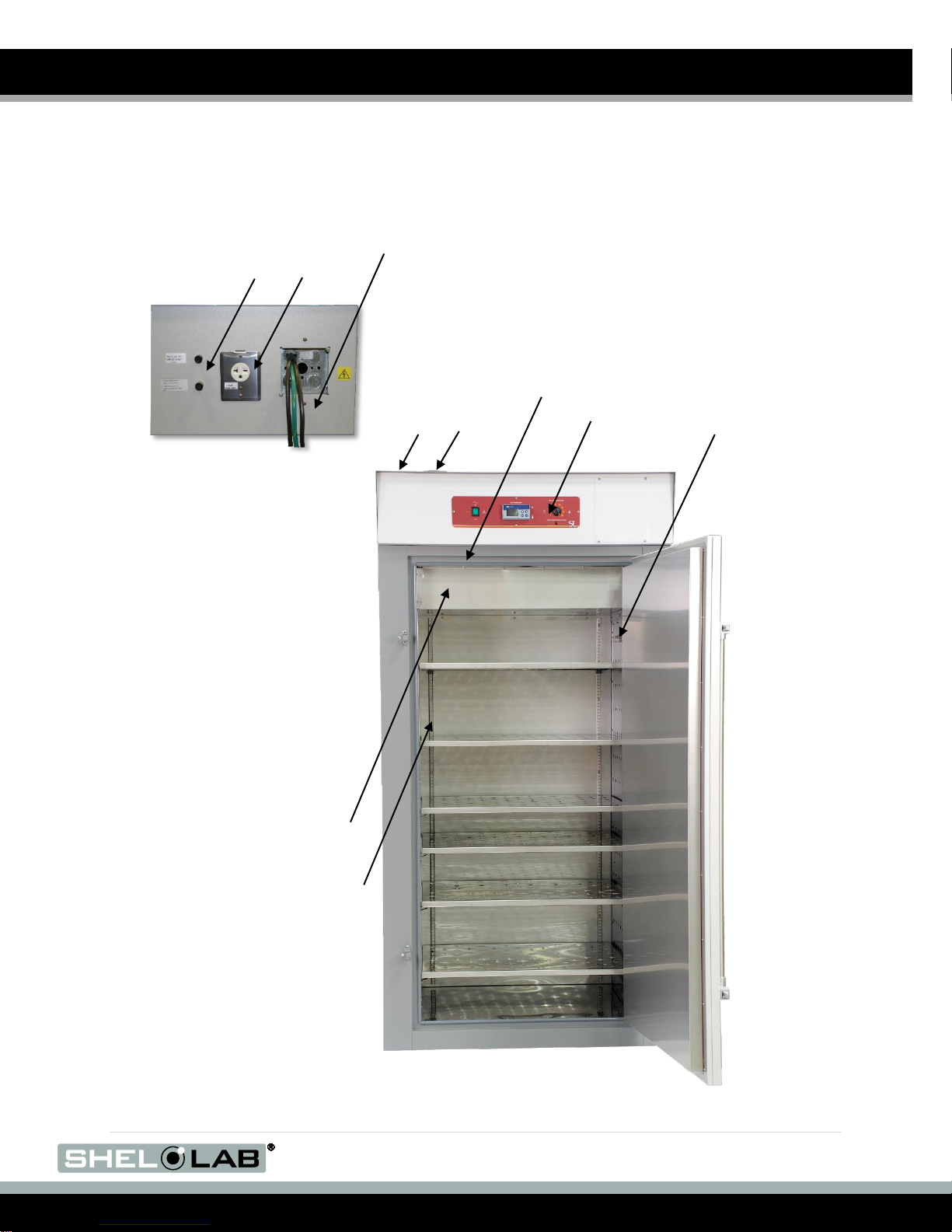
Figure 1: SMO34HP-2
Permanent Connect Wire Braid
6 gauge, 6 inches (15 cm)
Exhaust
Vent
Intake
Vent
Power Panel (Back)
Control Panel
Temperature
Sensor Probes
Chamber Gasket
Power Exhaust
Outlet 6-20R
Fuse Holders for External
Receptacle (2 amps each)
Chamber Ceiling Liner
Power Supply Feed
Shelf Standard Mounting
Rail
RECEIVING YOUR OVEN (CONTINUED)
ORIENTATION PHOTOS
7 | P a g e

Figure 2: SMO38HP-2
Power Panel
(Back)
Temperature Sensor
Probes
Chamber Ceiling Liner
Permanent Connect Wire Braid 6
gauge, 6 inches (15 cm)
Control Panel
Exhaust Vent
Intake Vent
Chamber Liner Gasket
Shelf Standard
Mounting Rail
Fuse Holders for External
Receptacle (2 amps each)
Power Exhaust
Outlet 6-20R
Power
Supply Feed
RECEIVING YOUR OVEN (CONTINUED)
8 | P a g e

Figure 3: SMO14HP-2
Intake Vent
Exhaust Vent
Control Panel
Chamber Gasket
Temperature
Sensor Probes
Chamber Ceiling Liner
Power Panel (Back)
Permanent Connect Wire Braid
10 gauge, 6 inches (15 cm)
Fuse Holders for External
Receptacle (2 amps each)
Power Exhaust
Outlet 6-20R
Power
Supply Feed
Shelf Standard Mounting Rail
RECEIVING YOUR OVEN (CONTINUED)
9 | P a g e

Shelf Standard Mounting Rail
Power Panel
(Back)
Fuse Holders for External
Receptacle (2 amps each)
Power Exhaust
Outlet 6-20R
Intake Vent
Exhaust Vent
Control
Panel
Chamber Ceiling
Liner
Door Gasket
Permanent Connect Wire Braid
10 gauge, 6 inches (15 cm)
Power
Supply Feed
Temperature
Sensor Probes
(In Chamber)
Figure 4: SMO10HP-2
RECEIVING YOUR OVEN (CONTINUED)
10 | P a g e
Model Number
Serial Number
RECEIVING YOUR OVEN (CONTINUED)
RECORDING DATA PLATE INFORMATION
Locate the data plate on the back of the oven next to the power inlet. The data plate contains the
oven model number and serial number. Enter this information below for future reference.
Date Plate Information
TEMPERATURE REFERENCE SENSOR DEVICE
The oven does not come with a temperature reference device. A reference sensor device must be
purchased separately for performing accuracy verifications or calibrations of the oven temperature
display.
The reference device must be accurate to at least 0.1°C, and should be regularly calibrated,
preferably by a third party.
For best results, use a digital device with a thermocouple or other remote reading probe. Remote
readings avoid oven chamber door openings during verification and calibration procedures. This
avoids subsequent waits for the chamber temperature to re-stabilize. Select a probe suitable for the
application temperature you will be calibrating or verifying the display accuracy at.
Alcohol thermometers are insufficient for conducting accurate verifications and calibrations. Do not use a
mercury thermometer. Never place a mercury thermometer in the oven chamber.
11 | P a g e

INSTALLATION
Installation of a High Performance Oven requires permanent connect wiring (commonly known as
hardwiring), and must be performed by a qualified electrical technician. All other steps can be
performed by the end user.
REQUIRED AMBIENT CONDITIONS
This oven is intended for use indoors, at room temperatures between 15C and 40C (59F and
104F), at no greater than 80% Relative Humidity (at 25C / 77F). Allow a minimum of 12 inches
(30cm) between the oven and any walls or partitions, and 24 inches (60cm) of vertical headspace
clearance above the top of the oven for unobstructed airflow and cooling. If the oven exhaust will be
vented from the workspace through a duct or other channeling, 12 inches (30cm) of vertical
clearance will suffice. Make sure the intake and exhaust vent remain unobstructed. Do not place
objects on top of oven, aside from the power exhaust accessory described in the manual.
Operating the unit outside of these conditions may adversely affect the oven temperature
range and stability. For conditions outside of those listed above, please contact your distributor or
Sheldon Sales to explore other ovens suited to your laboratory or production environment.
LOCATION CONSIDERATIONS
When selecting a location to install the oven, consider all environmental conditions that can affect
unit’s effective temperature range, uniformity, and stability. For example:
Other ovens, autoclaves, and any device that produces significant radiant heat
Heating and cooling ducts, or other sources of fast moving air currents
High-traffic areas
Direct sunlight
12 | P a g e

Model
Amperage
Model
Amperage
SMO10HP-2
26
SMO34HP-2
50
SMO14HP-2
26
SMO38HP-2
50
INSTALLATION (CONTINUED)
POWER SOURCE REQUIREMENTS
When selecting a location for the oven, check that each of the following requirements are satisfied:
The oven must be positioned so that all operators have access to the power feed
disconnect in case of emergencies.
o The Disconnect must be in close proximity to the equipment and within easy reach
of the operator.
o The Disconnect must be marked as the disconnecting device for the equipment.
The power source must be single (1) phase and protective earth grounded.
The power source must conform to all national and local electrical codes.
The power source voltage and ampere must match the power requirements listed on the
oven data plate (located on the back of the unit, beneath the power feed inlet).
o These ovens are intended for a 220 - 240 volt, 50/60 Hz applications at the
following amperages:
Supplied voltage must not vary more than 10% from the data plate rating. Damage to
the oven may result if supplied voltage varies more than 10%. Use a separate circuit to
prevent loss of the unit due to overloading or circuit failure.
A switch or circuit-breaker must be used in the building installation to protect against
overcurrent conditions.
o The required circuit-breakers are: SMO10HP-2 30 amps; SMO14HP-2 30 amps;
SMO34HP-2 60 amps; SMO38HP-2 60amps.
Power Exhaust Outlet Fuses
The oven is also provide with a pair (2) of 2 amp fuses installed adjacent to the external power
outlet on the back of the unit. The outlet is solely intended to power an optional power exhaust
blower attached to the oven exhaust vent. The fuses protect against overcurrent conditions related
to the operation of the outlet and attached blower. If one fuse blows, the outlet will depower. The
cause of a blown fuse should be determined prior to replacing it.
These fuses do not provide protection against overcurrent events associated with major
components of the oven. Overcurrent protection for the oven must be set up in the location power
supply external to the unit. See the circuit breaker requirements above.
13 | P a g e

INSTALLATION (CONTINUED)
POWER FEED WIRING
The oven comes provided with an integral 6 inch (15 cm) wire braid of:
SMO38HP-2, SMO34HP-2 – two 6 gauge hot wires and a 6 gauge earth ground.
SMO14HP-2, SMO10HP-2 – two 10 gauge hot wires and a 10 gauge earth ground.
The wires for power source connection should be in accordance with the following for all units:
Green/Yellow – Earth; Black – Hot; Black – Hot.
The oven must be earth grounded using the protective conductor terminal (green with yellow
stripe wire. Do not remove the protective conductor (earth connection). Removing the protective
conductor will negate the oven’s protections against potentially dangerous electric shocks and
create a possible fire hazard.
LIFTING AND HANDLING
The oven is heavy. Use appropriate lifting devices that are sufficiently rated for these loads. Follow
these guidelines when lifting the oven:
Lift the oven only from its bottom surface.
Doors, handles, and knobs are not adequate for lifting or stabilization.
Restrain the oven completely while lifting or transporting so it cannot tip.
Remove all moving parts, such as shelves and trays, and lock doors in the closed position
during transfers to prevent shifting and damage.
LEVELING
The oven must be level and stable for safe operation. Each High Performance Oven ships with four
leveling feet. Insert one leveling foot into each of the four holes in the bottom corners of the oven.
Stand the oven upright. Then, adjust the foot at each corner until the oven stands level and solid
without rocking. To raise a foot, turn it in a counterclockwise direction; to lower a foot, turn it in a
clockwise direction.
To prevent damage when moving the oven, turn each of the four leveling feet completely clockwise.
14 | P a g e

Figure 6: Installing Shelf Clip
Figure 5: Shelf Hung
Rocking
Motion
INSTALLATION (CONTINUED)
INSTALL THE OVEN
Install the unit in a workspace location that meets the criteria discussed in the previous entries of
the Installation section.
Do not connect the oven to its power source at this time.
INITIAL CLEANING
The unit was cleaned at the factory, but not sterilized. Additionally, it may have been exposed to
contaminants en route during shipping. See the Cleaning and Disinfecting topic in the User
Maintenance section (page 34) for more information on how to clean and disinfect the oven
chamber.
Remove all wrappings and coverings from shelving prior to cleaning and installation.
SHELVING INSTALLATION
The horizontal airflow within the chamber moves from the small duct holes on the right-hand side of
the chamber, to the large holes on the left side. Place the shelves so they do not obstruct the duct
holes on either side in order to maximize airflow across the shelf space.
Perform the following steps to install the SMO-HP shelves:
1. Install the shelf clips in the slots of the shelf standard rails located on the sides and rear of
the chamber interior.
a. Squeeze each clip.
b. Insert the top tab first, then the bottom tab using a rocking motion.
2. Hang the shelves from the clips.
3. Space the shelves out evenly in the incubation chamber to ensure the best possible air
circulation and temperature uniformity.
15 | P a g e

Symbol
Definition
Indicates that you should consult your service manual for further instructions.
Indique que l'opérateur doit consulter le manuel d'utilisation pour y trouver les instructions
complémentaires.
Indicates Adjustable Temperature
Indique température réglable
Indicates AC Power
Repère le courant alternative
Indicates I/ON and O/OFF
I repère de la position MARCHE de l'interrupteur d'alimentation
O repère de la position ARRÊT de l'interrupteur d'alimentation
Indicates protective earth ground
Repère terre électrique
Indicates UP and DOWN respectively
Touches de déplacements respectifs vers le HAUT et le BA
Indicates a Potential Shock Hazard
Signale danger électrique
Indicates the unit should be recycled (Not disposed of in land-fill)
Indique l’appareil doit être recyclé (Ne pas jeter dans une décharge)
Indicates: Caution hot surface
Indique: Avertissement symbole de surface chaude
GRAPHIC SYMBOLS
The oven is provided with multiple graphic symbols on its external and internal surfaces. The
symbols identify hazards and the functions of the adjustable components, as well as important
notes found in the user manual.
16 | P a g e

GRAPHIC SYMBOLS (CONTINUED)
This page left blank
17 | P a g e

Current Set Point
Current Oven Temperature
CONTROL PANEL OVERVIEW
Figure 7: Control Panel and Controller
Power Switch
Labeled Power, this illuminated switch controls all power to the oven. It must be in the On ( I )
illuminated position before any systems are operational.
Set Temperature: The Temperature Display and Controller Unit
The temperature display and controller unit for large capacity SMOHP-2 ovens is a JUMO dTRON.
After booting up, the display shows the homepage. The homepage shows the current oven
chamber air temperature in red (top), and the current temperature set point in green (bottom). Both
are in degrees Celsius.
Figure 8: Display Home Page
The orange numerical indicators on the lowest level of the display indicate internal communication
processes within the controller and between the controller and the oven. An orange ramp symbol
illuminates when the controller is running a heating profile.
Controller Modes
As shipped from the factory, the controller boots up in its heating profile function mode, ready to
be programed and then launch a profile. While on the home page in heating profile mode, the up
arrow button launches the heating profile, if one has been programed. This button also aborts a
heating profile, if pressed again while the profile is running.
Pressing the down arrow unlocks the green temperature set point when a profile is not running.
Both arrow keys can then be used to adjust the unlocked set point. After an adjustment is entered,
and no key is pressed for 3 seconds, the green set point will blink and lock, and the oven will begin
to heat or passively cool to match the adjusted set point. It will then run indefinitely at that set point
until adjusted again, or until a heating profile is launched. Or until the oven is turned off.
18 | P a g e

CONTROL PANEL OVERVIEW (CONTINUED)
The oven can also be placed in a single set point function mode. In this mode a heating profile
cannot be launched and the profile programing page cannot not be accessed. However, the
temperature set point is always unlocked. This allows a user to manually control heating by
adjusting the set point at any time using the arrow keys.
Other Arrow Key Uses
The up and down arrow buttons are also used to scroll menu options on menu pages. On heating
profile programing pages, the up arrow is used to return to the previous step parameter page. The
down arrow advances to the next parameter page.
Program and Exit Buttons.
On the Home Page, pressing the Program button (PGM) changes the display to show the
Programing / Configuration Menu page. When programing a heating profile, the Program button is
used to advance between parameters, and unlocks most parameters for adjustment. Parameters
blink continually when unlocked. Pressing the Program button while a parameter is blinking will
save the currently shown value as the new parameter value, and advance to the next parameter.
The Exit button returns the display to the previous page, and can also be used to take a parameter
out of its flashing adjustable mode. Doing so also restores the parameter to its last saved value,
rather than saving the last shown value.
Set Over Temperature
This graduated dial sets the temperature cut off point for the OTL heating cut off system. The OTL
is a redundant mechanical system that reroutes power away from the heating elements whenever
the chamber temperature exceeds the current OTL cut off setting. This prevents unchecked heating
of the chamber in the event of a failure of the digital controller unit or its sensor probe while in
heating mode.
The red Over Temp Activated light illuminates whenever the Over Temperature Limit system routed
power away from the elements.
19 | P a g e

OPERATION (CONTINUED)
This page left blank
20 | P a g e

OPERATION
OPERATING PRECAUTIONS
Warning: The High Performance Oven is not an explosion proof unit!
Avertissement: Ce sont des fours pas résistants aux explosions!
1. These ovens are not designed to safely contain flammable or combustible gasses,
vapors, or liquids.
2. Do not place combustible or flammable materials into the chamber, or items that have
been processed with or tainted by combustible or flammable substances.
3. The bottom surface of the chamber should not be used as a work surface.
4. Never place samples or product on oven chamber floor.
5. Do not operate the oven in an environment with noxious fumes.
6. Outgassed byproducts maybe hazardous to or noxious for operating personal. If either
is the case, oven exhaust should be positively ventilated to a location outside workspace
in accordance with national and local regulations.
7. Do not place sealed or filled containers in the oven. These may burst open when the
chamber is under vacuum.
8. Do not place alcohol or mercury thermometers in the oven.
9. The oven is not designed for use in Class I, II, or III locations as defined by the US
National Electric Code.
Warning: The vent dampers may be hot to the touch. These areas are marked with Hot Surface labels.
Proper PPE should be employed to minimize risk to burn.
Avertissement: Les clapets d'aération peuvent être chauds au toucher. Ces zones sont marqués
avec des étiquettes de Surface chaude. Les EPI approprié devraient être employée pour réduire au
minimum le risque de brûler.
21 | P a g e

OPERATION (CONTINUED)
Heating
The operation of each SMOHP-2 oven is controlled by a JUMO dTRON digital controller, wired to a
solid state temperature probe located on the right wall of the oven chamber. The controller employs
proportional-integral-derivative analytical feedback-loop functions when measuring and controlling
the chamber air temperature. PID-controlled heating pulse intensities and lengths are proportional
to the difference between the measured chamber temperature and the current set point. The
frequency of pulses are derived from the rate of change in that difference. The integral function
slows the rate of pulses when the temperature nears the set point to avoid overshooting.
The JUMO operates in one of two user-selected modes: The heating profile mode and single set
point mode. The heating profile mode allows the user to program and launch the heating profile,
but requires unlocking the current set point to adjust the temperature set point. The temperature set
point cannot be adjusted while a profile is running. The single set point mode unlocks the green
temperature set point on the home page. This allows the user to adjust the current set point at any
time with the arrow buttons, without unlocking the set point. However, this mode prevents the
launch of a profile and blocks access to the profile programing menu.
The lowest temperature the oven can achieve when powered is the room temperature (ambient)
+10°C.
The JUMO controller stores a one heating profile with twenty four (24) programmable steps.
Each step has three programmable parameter values: the temperature set point, the time period,
and an option controller value. The option controller value activates or deactivates an external
exhaust blower fan plugged into the external power outlet and mounted on the oven exhaust vent.
The external exhaust blower must be purchased separately. Please see the Operation and
Programing JUMO dTRON Guide for how to program a heating profile.
The heating rates given for the oven are for a 25°C environment. The ambient temperature of the
workspace around the oven affects heating and cooling rates.
Airflow and Applications
To achieve stated performance specs, the oven intake and exhaust vents must be fully closed.
Operating the oven with the vents open impacts the oven chamber temperature uniformity and
stability. This may speed drying rates, depending on the nature of your samples or product.
Running the oven with an active power exhaust blower attached will reduce the oven chamber
temperature. The vents are intended to be open after completion of a heating profile or other
baking application to speed drying.
During normal operations an internal blower fan motor circulates air through the chamber and a
heating duct located above the chamber in a closed circuit. Heated air is routed into a duct that
makes up the right wall of the chamber. Air exits through small holes and blows horizontally across
the shelf space. This helps create temperature uniformity and enhances drying. The air then enters
a duct on the left side of the chamber through larger holes, and is pulled back up into the heating
duct above the oven chamber. If one or both vents are open, the rate of atmosphere exchange
between the chamber and surrounding workspace depends on several variable factors. These
include: ambient conditions, the volume of material in the oven chamber, and if an active power
exhaust unit is connected to the exhaust vent.
22 | P a g e

OPERATION (CONTINUED)
Power Exhaust Outlet
SMOHP-2 Ovens come provided with an external power outlet that can be used to power a blower
exhaust fan attached to the oven exhaust vent. The power outlet and attached fan can be activated
by the oven controller as part of the heating profile. The primary application of an external power
exhaust blower is to force noxious or hazardous oven exhaust away from the oven workspace
through a duct or other venting. A power exhaust increases the rate of air exchange within the oven
chamber, and impacts temperature performance and cooling rates by removing heated chamber
air.
The Over Temperature Limit System
The OTL is a backup mechanical heating control system that operates independently of the oven
digital controller. It consists of a mechanical thermostat control wired by a fluid capillary to an
independent hydrostatic temperature probe located on the right wall of the oven chamber. The OTL
system prevents runaway heating by routing power away from the oven heating elements
whenever the air temperature in the chamber exceeds the OTL cutoff setting.
23 | P a g e

Controller Display
Homepage
Chamber Temp in Red
Current Set Point in
Green
OPERATION (CONTINUED)
PREPARING THE OVEN FOR USE
Preform the following steps to prepare the oven for use after installing it in a new workspace environment.
The First Use Burn-In procedure is intended to remove any traces of protective oil coatings from the oven
elements and prevent smoking during your first application or heating profile run above 150°C. This also
removes any residual cleaning agents left on the oven chamber surfaces. The procedure only needs to
be performed once, after receiving the oven from the factory.
1. Open the intake and the exhaust vents of the First Use Burn-in Procedure.
2. Attach any ducting to the exhaust vent at this time.
3. Place the Power Switch to the ON position.
a. The controller display will illuminate and load its
homepage.
4. Set up the oven for use by carrying out the following
procedures in order, found in the Operation section:
Prepare for First Use Burn-In, page 24
Set the Temperature Set Point for the burn-in, page 25
First Use Burn-In, page 26
Optional: Temperature Verification, page 28
Set the Over Temperature Limit for you application temperature, page 30
PREPARE FOR FIRST USE BURN-IN
If the oven is being run for the first time out of the box, perform the steps below followed by the
Burn-In procedure to burn off the protective oil coating from the oven heating element.
1. If not already set to its maximum position, turn the OTL control dial all the way to the
right (clockwise) so that it does not interfere with the Burn-In process.
a. The OTL should come from the factory set to its maximum position.
2. Positively vent the oven exhaust outside of its workspace environment during the
Burn-In Procedure. The procedure will produce light smoking.
a. The smoke should be non-toxic, but may be noxious.
3. Use the Set the Temperature Set Point procedure on the next page to set the oven to
run at 200C°.
24 | P a g e

Unlock and Adjust the Heating Set Point
1. Unlock the Set Point
a. Press and hold the down arrow button until the green set point
(bottom) begins to blink.
Home Page
2. Adjust the blinking set point to your application set point (200°C for the
First Use Burn-In).
a. Use the Up and Down arrow keys.
Note: After 3 seconds or more of no activity, the set point will lock, cease blinking,
and store the last displayed value as the new set point.
New Set Point
3. After adjusting to the set point, wait 3 seconds.
a. The controller will save and lock the new set point value
b. Allow the oven time to heat to the set point. The oven will run
indefinitely at this temperature.
Heating
OPERATION (CONTINUED)
SET THE TEMPERATURE SET POINT
Note: Set the oven temperature to 200°C for the First Use Burn-In Process.
There are three ways to set the oven chamber temperature. You may use any of these for the
Burn-In procedure.
Program and launch a heating profile. A profile can run the oven at a single steady state
temperature, or include heat soaks at multiple set points, as well as the ramp up and ramp
down times needed to heat up to or cool down to these temperatures.
o Please see pages 5 – 15 of the Operation and Programming Guide – JUMO
dTRON that came with this oven for how to program and launch or abort a heating
profile.
Place the oven in its single set point function mode. After placing the unit in the single
set point mode, use the arrow buttons to adjust the set point to your application
temperature set point. The oven will ramp up to this temperature and run at it indefinitely.
o Please see pages 16 – 17 of the Operation and Programming Guide – JUMO
dTRON for how to place the unit in single set point mode.
Unlock and adjust the temperature set point. This is the simplest option when
performing the First Use Burn-In, and leaves the oven controller in its heating profile
function mode. See below.
25 | P a g e

OPERATION (CONTINUED)
FIRST USE BURN IN
Employ appropriate personal protective equipment (PPE) when handling the vent dampener slides.
1. Verify that oven exhaust is positively vented from the workspace area.
2. Allow the oven to heat to 200°C.
3. After reaching 200°C, allow the oven run for a minimum of 1 hour at temperature.
a. If still producing smoke after 1 hour, run at 200°C until smoke from the heating
elements dissipates.
After the Burn-In is complete, you may set the oven to run at your application constant temperature
set point or program a heating profile. You may also perform an optional accuracy verification of the
temperature display.
Always set the Over Temperature Limit before starting normal operations.
26 | P a g e

OPERATION (CONTINUED)
This page left blank
27 | P a g e

Figure 9: Damper
in Closed Position
Figure 10: Probe End
2 inches (5cm) From
Shelf Surface
OPERATION (CONTINUED)
TEMPERATURE ACCURACY VERIFICATION
Note: Performing an accuracy verification of the temperature display requires a temperature
reference device. Please see the Reference Sensor Devices entry on page 11 for device
requirements.
Optional: A verification of the temperature display accuracy may be carried out when preparing the
oven for use, if required by your production or laboratory protocol. The verification compares the
displayed temperature of the oven chamber with the actual temperature of the chamber air as
provided by a reference sensor device.
If a difference between the actual and displayed temperatures is
discovered, perform a temperature calibration. Please see the Calibrate
Temperature Display procedure on page 36 in the User Maintenance
section.
Vents
The intake and exhaust vents must be closed in order to perform an
accurate temperature verification. Chamber temperature uniformity and
stability are too disrupted when operating with the vents open to verify the
accuracy of the oven temperature display.
Probes
A reference device sensing probe may be introduced through the through
the chamber door space. Use heat-resistant, non-marking tape to secure
the wires and probe heads, and seal any gaps in the door space. The door
must close and latch fully.
Place the sensor probe of the temperature reference device as close as
possible to the geometric center of the oven chamber. A thermocouple
sensor probe sleeve may be taped to the shelving, as long as the exposed
copper end is 2 inches (5cm) away from the shelf (see Figure 10). An
exposed sensor probe in direct contact with the shelving may experience
heat sinking, which can result in an inaccurate temperature reading.
Pre-Heating
For best accuracy, set the oven temperature set point to that of your application. If you will be
running a multi-set point heating profile, set the oven to run at the average temperature of your
profile. Let the oven heat to the constant temperature set point and run for at least 1 hour
undisturbed in order to stabilize.
Temperature Stability
The oven chamber is thermally stabilized when no fluctuations of ±0.2C or greater have been
detected with the verification reference device for a minimum of 30 minutes. Failure to wait for
stabilization will result in a failure to verify the accuracy of the oven temperature display reading.
28 | P a g e

Verifying the Temperature Display Accuracy
1. Once the chamber temperature has stabilized, compare the reference
device and the oven display temperature readings.
a. If the readings are the same, or the difference between the two (2)
falls within the acceptable range of your protocol, the display is
accurately showing the oven chamber air temperature. The
Temperature Verification procedure is now complete.
b. See step 2 if a difference falls outside the acceptable range of your
protocol.
Reference Device
2. Perform a temperature calibration to match the controller display to
the actual chamber temperature if a difference falls outside your
protocol range.
a. Please see 36 in the User Maintenance section.
Reference Device
OPERATION (CONTINUED)
End of procedure
29 | P a g e

Set the OTL Cutoff Temperature
Example
1. Turn the Set Over Temperature Limit control dial clockwise to the
maximum position, if it is not already set to maximum.
2. Set the oven to run at either your single set point application
temperature, or a set point equal to the highest temperature of your
application heating profile.
3. Wait 30 minutes after the oven has achieved the set point for the
chamber to stabilize, before setting the OTL
4. Turn the Over Temperature Limit control dial co unterclockwise
until the red Over Temperature Limit Activated light illuminates.
5. Slowly turn the dial clockwise until the Over Temperature Limit
Activated light turns off. Stop turning the control.
a. The Over Temperature Limit is now set approximately 5˚C
above the current chamber temperature.
6. Optional: You may turn the dial slightly to the left to bracket in
closer to the set point temperature. This sets the OT Limit nearer
to the current chamber temperature.
7. Leave the OTL dial set just above the activation point.
OPERATION (CONTINUED)
SET THE OVER TEMPERATURE LIMIT
Note: Test the OTL system for functionality at least once per year.
This procedure sets the Over Temperature Limit heating cutoff to approximately 5˚C above the
current chamber temperature.
If the OTL sporadically activates after setting the control, you may turn the dial very slightly to the
right (clockwise).
30 | P a g e

OPERATION (CONTINUED)
OTL ACTIVATION DURING NORMAL OPERATIONS
The following may be taking place if the OTL system activates during normal operations:
A user has set the Over Temperature Limit below the current set point for either an active
heating profile or single constant temperature set point.
An external heat source or heat source inside the chamber is causing the chamber air
temperature to spike.
The temperature controller and display unit or its sensor probe has failed, and must be
replaced in order to maintain safe operation of the oven.
If the OTL activated during normal operations adjust it very slightly clockwise to increase the
setting. If the OTL continues to interrupt heating of the oven chamber and there no obvious external
sources of nearby heating (autoclaves, another oven), depower the oven and allow the oven
chamber to cool before opening the oven door or troubleshooting.
PROGRAMMING A HEATING PROFILE
Please see the Operation and Programing JUMO dTRON Guide included with the oven for how to
program, launch, and abort a heating profile.
31 | P a g e

Figure 11: High Performance
Power Exhaust
(Part Number 9990741)
OPERATION (CONTINUED)
POSITIVE VENTING OF EXHAUST
Exhaust ducting can be connected to the oven exhaust port in order to
channel outgassed products out of the workspace around the oven. An
attached exhaust duct should not extend straight up from the oven, but
should include a steep bend sufficient to stop condensation in the
ducting from sliding down into the oven.
Shel Lab offers a 230 volt High Performance Power Exhaust that can
be mounted directly on the oven exhaust vent and attached to exhaust
ducting. This allows for positive venting. When plugged into the oven’s
external power outlet, the operations of the exhaust blower is
controlled by the heating profile.
Mounting the Power Exhaust
1. Remove the screws on the cover of the exhaust vent assembly on the top of the oven, but
leave the assembly in place.
2. Mount the exhaust blower on the exhaust vent cover assembly, aligning the blower and the
assembly’s screw holes.
a. The open side of the blower’s mounting body should go over the sliding handle of the
exhaust port’s vent cover.
3. Reinstall the screws to secure the exhaust vent assembly and exhaust blower to the oven.
4. Plug the power exhaust into the 230 volt outlet on the back of the oven.
Activating and Deactivating the Power Exhaust
The power exhaust may be run during any step of a heating profile, except the terminating step. To
run the exhaust blower, change the step’s option control parameter from 0000 to 0100 while
programing the profile. 0000 is the default off state; 0100 activates the external electrical outlet on
the back of the oven.
The blower will run for the full duration of the step. The option control parameter must be set to
0100 for each step you wish to run it during.
32 | P a g e

OPERATION (CONTINUED)
This page left blank
33 | P a g e

USER MAINTENANCE
Warning: Prior to maintenance or service on this unit, disconnect the power feed from the power supply.
Avertissement: Avant d'effectuer toute maintenance ou entretien de cet appareil, débrancher le cordon
secteur de la source d'alimentation.
CLEANING AND DISINFECTING
If a hazardous material or substance has spilled in the oven, immediately initiate your site’s
Hazardous Material Spill Containment protocol. Contact your local Site Safety Officer and follow
instructions per the site policy and procedures.
The oven chamber should be cleaned prior to first use.
Do not use spray on cleaners or disinfectants. These can leak through openings and coat electrical
components. Do not use cleaners or disinfectants that contain solvents capable of harming paint
coatings or stainless steel surfaces. Do not use chlorine-based bleaches or abrasives; these
will damage the chamber liner.
Consult with the manufacturer or their agent if you have any doubts about the compatibility of
decontamination or cleaning agents with the parts of the equipment or with material contained in it.
Warning: Never clean the unit with alcohol or flammable cleaners.
Avertissement: Ne jamais nettoyer l'appareil à l'alcool ou avec des nettoyants inflammables.
Cleaning
1. Remove all non-attached chamber components and accessories (shelves, racks, and
any additional items), if present.
2. Clean the chamber interior with a mild soap and water solution, including all corners.
3. Take special care when around cleaning chamber sensor probe located on the right wall.
4. Clean all removable accessories and components.
5. Rinse the chamber surfaces and shelving with distilled water and wipe dry with a soft
cloth. Do not use deionized water.
Deionized is an aggressive solvent that will attack most metals. Never use deionized water to
clean your oven, even if it is readily available in your laboratory or production workspace.
34 | P a g e

MAINTENANCE (CONTINUED)
Disinfecting
Disinfect the oven if algae, mold, bacteria, or other biological contaminants are an issue. For
maximum effectiveness, disinfection procedures are typically performed after cleaning and removal
of gross matter contamination. Perform the following steps to manually disinfect the oven:
1. Turn the unit off. Open all doors and carryout your laboratory or production space
disinfection protocol.
2. Disinfect the oven chamber using commercially available disinfectants that are noncorrosive, non-abrasive, and suitable for use on stainless steel surfaces. If disinfecting
external surfaces use disinfectants that will not damage painted cold roll metal or plastic.
Contact your local Site Safety Officer for detailed information on the disinfectants
compatible with your application or process.
3. If permitted by your protocol, remove all interior accessories (shelving and other nonattached items) from the chamber when disinfecting.
4. Disinfect all surfaces in the chamber, making sure thoroughly disinfect the corners.
Exercise care to avoid damaging the sensor probes.
ELECTRICAL COMPONENTS
Electrical components do not require maintenance. If the oven fails to operate as specified, please
contact your Shel Lab distributor or Sheldon Manufacturing Technical Support for assistance.
DOOR GASKETS AND CHAMBER INTEGRITY
Periodically, inspect the door latch, trim, catch, and silicon door gasket for signs of deterioration.
Failure to maintain the integrity of the door system shortens the life span of the Oven and affects
temperature performance.
35 | P a g e

Figure 12: Vent Damper
in Closed Position
Figure 13: Probe End
2 inches (5cm) From
Shelf Surface
USER MAINTENANCE (CONTINUED)
CALIBRATE THE TEMPERATURE DISPLAY
Note: Performing a temperature display calibration requires a temperature reference device.
Please see the Reference Sensor Devices entry on page 11 for device requirements.
Temperature calibrations are performed to match the temperature display to the actual air
temperature inside the oven chamber. The actual air temperature is supplied by a reference sensor
device. Calibrations compensate for drifts in the controller as well as those caused by the natural
material evolution of the sensor probe under temperature in the chamber space. Calibrate as often
as required by your laboratory or production protocol, or regulatory compliance schedule.
Vents
The vent dampeners must be close in order to perform an accurate display
calibration. Chamber temperature uniformity and stability are too disrupted
when operating with the vents open to verify the accuracy of the oven
temperature display.
Probes
A reference device sensing probe may be introduced through the through
the chamber door space. Use heat-resistant, non-marking tape to secure
the wires and probe heads, and seal any gaps. The door must close and
latch fully.
Secure the wiring and cover any gaps in the door space using heatresistant, non-stick tape.
Place the sensor probe of the temperature reference device as close as
possible to the geometric center of the oven chamber. A thermocouple
sensor probe sleeve may be taped to the shelving, as long as the exposed
copper end is 2 inches (5cm) away from the shelf (see Figure 13). An
exposed sensor probe in direct contact with the shelving may experience
heat sinking, which can result in an inaccurate temperature reading.
Pre-Heating
For best accuracy, set the oven temperature set point to that of your application. If you will be
running a multi-set point heating profile, set the oven to run at the average temperature of your
profile. Let the oven heat to the constant temperature set point and run for at least 1 hour
undisturbed in order to stabilize.
Temperature Stability
The oven chamber is thermally stabilized when no fluctuations of ±0.2C or greater have been
detected with the verification reference device for a minimum of 30 minutes. Failure to wait for
stabilization will result in an inaccurate calibration and oven temperature display reading.
36 | P a g e

Temperature Calibration
1. Once the chamber has stabilized with no fluctuations of ±0.2˚C or greater
compare the reference temperature device and chamber temperature
display readings.
a. If the readings are the same, or the difference between the two (2)
falls within the acceptable range of your protocol, the display is
accurately showing the chamber temperature. The Temperature
Verification procedure is now complete.
b. See step 2 if a difference falls outside the acceptable range of your
protocol.
Reference Device
Home Page
2. The display requires calibration.
a. The difference (also known as an error) between the reference
device and the display is an offset.
Examples of offset values:
Reference Sensor
Reading
Oven Temp.
Display
Offset
Value
152.0°C
150°C
2
147.0°C
150°C
-3
b. Note the offset value.
Reference Device
Home Page
Correcting an Offset
3. Jump to the Operations Menu.
a. Press the Program button.
Oprations Menu
4. Scroll to the Configuration Option.
a. Press the up arrow button until the “Conf” option appears.
Configuration Option
USER MAINTENANCE (CONTINUED)
Continued on next page
37 | P a g e

Temperature Calibration (Continued)
5. Enter the Configuration menu.
a. Press the Program button to enter the Configuration menu.
b. The Input option “InP” will be the first to appear in the Configuration
menu.
Configuration Menu
6. Enter the Input menu.
a. Press the Program button to enter the Input menu.
b. The Input 1 option will be the first to appear in the Input menu.
The Input Menu
7. Enter the Input 1 Menu.
a. Press the Program button to enter the Input 1 menu.
b. Sens will be the first option to appear in this menu.
Sens Option
8. Use the arrow keys to scroll to the “OFFS” Offset parameter.
a. Scroll to the Offset calibration parameter to enter the offset.
Offset Parameter
9. Enter the temperature offset.
a. Press the Program button unlock the Offset parameter and place it in
its blinking adjustable mode.
b. Use the arrow keys to enter the offset.
-3 Offset Entered
USER MAINTENANCE (CONTINUED)
38 | P a g e
Continued on next page

Temperature Calibration (Continued)
10. After entering the offset wait two to three seconds.
a. The green “OFFS” parameter will cease flashing.
b. The newly input red offset will blink once, confirming that it has been
saved.
Offset Saved
11. Return to the Homepage.
a. Press the Exit button four times to return to the home page.
b. The oven will begin to adjust to the match the offset.
Homepage, Heating
12. Once the temperature has stabilized, compare the reference device and the
oven display temperature readings.
a. If the readings are the same, or the difference between the two
falls within the acceptable range of your protocol, the oven is
calibrated for temperature. The Temperature Calibration
procedure is complete.
b. See next step if the difference between the readings stills falls
outside your protocol acceptable range.
Reference Device*
Set Temperature
13. If the two readings still fall outside your protocol acceptable range, repeat 2 –
12 up to two more times.
a. If the temperature reading difference fall outside your protocol
after three calibration attempts, contact Technical Support or
your distributor for assistance.
b. Three calibration attempts may be required to successfully
calibrate units that are more than ±2°C out of calibration.
Reference Device*
Set Temperature
USER MAINTENANCE (CONTINUED)
End of procedure
39 | P a g e

Model
Shipping
SMO10HP-2
660 lbs. / 299.4kgs
SMO14HP-2
555 lbs. / 251.7kgs
SMO34HP-2
675 lbs. / 306.2kgs
SMO38HP-2
1025 lbs. / 465.0kgs
Model
Exterior W × D × H
Interior W × D × H
SMO10HP-2
44 x 28.25 x 55.1 in
30 x 19.75 x 30.1 in
SMO14HP-2
59 x 29 x 57 in
44 x 20.5 x 36 in
SMO34HP-2
43 x 34.25 x 85.5 in
31.5 x 26 x 60.5 in
SMO38HP-2
68.5 x 33 x 78.5 in
48 x 25.5 x 54 in
Model
Exterior W × D × H
Interior W × D × H
SMO10HP-2
112 x 72 x 142 cm
65.5 x 68 x 62 cm
SMO14HP-2
149.8 x 73.6 x 144.8 cm
76 x 50 x 77 cm
SMO34HP-2
109 x 87 x 217 cm
80 x 66 x 153.6 cm
SMO38HP-2
174 x 83x 199 cm
121 x 64.7 x 137 cm
UNIT SPECIFICATIONS
These ovens are 220 - 240 voltage units. Please refer to the oven’s data plate for individual
electrical specifications.
Technical data specified applies to units with standard equipment at an ambient temperature of
25°C and a voltage fluctuation of ±10%. The temperatures specified are determined in accordance
to factory standard following DIN 12880 respecting the recommended wall clearances of 10% of the
height, width, and depth of the inner chamber. All indications are average values, typical for units
produced in the series. We reserve the right to alter technical specifications at all times.
WEIGHT
DIMENSIONS
By Inches
By centimeters
40 | P a g e

Model
Cubic Feet
Liters
SMO10HP-2
10.0
283
SMO14HP-2
14.6
413
SMO34HP-2
28.0
792
SMO38HP-2
38.0
1083
Model
Per Shelf
Total
SMO10HP-2
75 lbs / 34 kg
225 lbs / 102 kg
SMO14HP-2
75 lbs / 34 kg
440 lbs / 204 kg
SMO34HP-2
75 lbs / 34 kg
440 lbs / 204 kg
SMO38HP-1
75 lbs / 34 kg
900 lbs / 408 kg
Model
Range
Uniformity
Stability
SMO10HP-2
Amb. +10 to 260C
+2.3C @ 150C
0.2°C
SMO14HP-2
Amb. +10 to 260C
+ 2.3C @ 150C
0.2°C
SMO34HP-2
Amb. +10 to 260C
+ 2.0C @ 100C
0.2°C
SMO38HP-2
Amb. +10 to 260C
+ 2.5C @ 150C
0.2°C
Model
AC Voltage
Amperage
Frequency
Phase
SMO10HP-2
220 - 240
26
50/60 Hz
1
SMO14HP-2
220 - 240
26
50/60 Hz
1
SMO34HP-2
220 - 240
50
50/60 Hz
1
SMO38HP-2
220 - 240
50
50/60 Hz
1
UNIT SPECIFICATIONS (CONTINUED)
CAPACITY
SHELF CAPACITY BY WEIGHT
TEMPERATURE
POWER
41 | P a g e

Description
Parts Number
Adjustable Feet:
2700506
Chamber Gasket Silicon
(Unit of purchase is per foot)
SMO10HP-2 requires 11.5 feet
SMO14HP-2 requires 9 feet per door
SMO34HP-2 requires 17 feet
SMO38HP-2 requires 28 feet per door
3450722
Power Exhaust Blower Unit 220 Volt, all models.
9990741
Shelf Clip
1250512
Shelf 18.6 x 19.5, SMO14HP-2
5120871
Shelf Assembly, 19 x 29, SMO10HP-2
995-00007
Shelf Assembly, 23 x 31, SMO34HP-2
995-00005
Shelf 21 x 23, SMO38HP-2
5120941
REPLACEMENT PART LIST
If you have the Part Number for an item, you may order it directly from Sheldon Manufacturing by
calling 1-800-322-4897 extension 3. If you are uncertain that you have the correct Part Number, or
if you need that specific item, please contact Sheldon Technical Support for help at 1-800-322-4897
extension 4 or (503) 640-3000. Please have the model number and serial number of the unit
ready, as Tech Support will need this information to match your oven with its correct part.
42 | P a g e

REPLACEMENT PART LIST
This page left blank
43 | P a g e

 Loading...