

Page 1

VACUUM OVEN
SVAC1 SVAC1-2
SVAC2 SVAC2-2
SVAC4 SVAC4-2
Previously designated as
1425, 1425-2
1445, 1445-2
1465, 1465-2
INSTALLATION AND OPERATION MANUAL
Revised 6 / 2014
4861531
Sheldon Manufacturing Inc. P.O. Box 627 Cornelius, Oregon 97113
EMAIL: tech@Shellab.com INTERNET: http://www.Shellab.com/~Shellab
1-800-322-4897 (503) 640-3000 FAX (503) 640-1366
Page 2

2
TABLE OF CONTENTS
SECTION 1.0 RECEIVING AND INSPECTION
SECTION 2.0 GRAPHIC SYMBOLS
SECTION 3.0 INSTALLATION
SECTION 4.0 PRECAUTIONS
SECTION 5.0 CONTROL PANEL OVERVIEW
SECTION 6.0 VACUUM OPERATION
SECTION 7.0 OPERATION
SECTION 8.0 MAINTENANCE
SECTION 9.0 TROUBLESHOOTING
SECTION 10.0 PARTS LIST
UNIT SPECIFICATIONS
SCHEMATICS
REFERENCE INFORMATION
APPENDIX
These units are TUV CUE listed as vacuum ovens for professional, industrial or
educational use where the preparation or testing of materials is done at approximately
atmospheric pressure and no flammable, volatile or combustible materials are being
heated. These units have been tested to the following requirements:
CAN/CSA C22.2 No. 61010-1:2012
CAN/CSA C22.2 No. 61010-2-010 + R:2009
UL 61010A-2-010:2002
UL 61010-1:2012
EN 61010-1:2010
EN 61010-2-010:2003
Page 3

3
INTRODUCTION
Thank you for purchasing our product. We know that in today’s competitive market place, customers have many
choices when purchasing constant temperature equipment. We appreciate your choosing our quality product. Our
continued reputation as a leading laboratory product manufacturer rests with each and every customer. Sheldon
Manufacturing, Inc. stands behind our products and want to let you know we are here if you need us.
Before you use the unit, read this entire manual carefully to understand how to install, operate, and maintain the unit
in a safe manner. Your satisfaction with the unit will be maximized as you read about its safety and operational
features.
Keep this manual on-hand so it can be used by all operators of the unit. Be sure all operators of the unit are given
appropriate training before you put the unit in service.
Note: Use the unit only in the way described in this manual. Failure to follow the guidelines and instructions in this
manual may be dangerous and illegal.
General Safety Considerations
Your oven and its recommended accessories have been designed and tested to meet strict safety requirements.
For continued safe operation of your oven, always follow basic safety precautions including:
Read this entire manual before using the oven.
Be sure you follow any city, county, or other ordinances in your area regarding the use of this unit.
Use only approved accessories. Do not modify system components. Any alterations or modifications to your
incubator may be dangerous and will void your warranty.
Always plug the unit’s power cord into a grounded electrical outlet that conforms to national and local electrical
codes. If the unit is not grounded, parts such as knobs and controls may conduct electricity and cause serious
injury.
Do not connect the unit to a power source of any other voltage or frequency beyond the range stated on the
power rating on the data plate of the unit.
Do not modify the power cord provided with the unit. If the plug does not fit an outlet, have a proper outlet
installed by a qualified electrician.
Avoid damaging the power cord. Do not bend it excessively, step on it, place heavy objects on it. A damaged
cord can easily become a shock or fire hazard. Never use a power cord after it has become damaged.
Do not position the equipment in such a manner as to make it difficult to disconnect power cord or coupler.
Do not attempt to move the unit while in operation or before the unit has been allowed to cool.
Page 4

RECEIVING AND INSPECTION
Model Number
Serial Number
Part Number
Voltage
Section
IMPORTANT: READ THIS INSTRUCTION MANUAL IMMEDIATELY.
Your satisfaction and safety require a complete understanding of this unit, including its proper function and
operational characteristics. Be sure operators are given adequate training before attempting to put unit in
service. NOTE: This equipment must be used only for its intended application; any alterations or modifications
will void your warranty.
1.1 Inspection: The carrier, when accepting shipment, also accepts responsibility for safe delivery and is liable for
loss or damage claims. On delivery, inspect for visible exterior damage. Note and describe on the freight bill any
damage found and enter your claim on the form supplied by the carrier.
1.2 Inspect for concealed loss or damage on the unit itself, both interior and exterior. If any, the carrier will arrange
for official inspection to substantiate your claim. Save the shipping crate until you are sure the unit has been
delivered in good condition.
1.3 Return Shipment: If for any reason you must return the unit, contact your customer representative for
authorization. Supply the complete data plate information when requesting return authorization. Please see the
manual cover for information on where to contact customer service.
1.4 Accessories: Verify all of the equipment indicated on the Ship Kit list included with the unit. Carefully check all
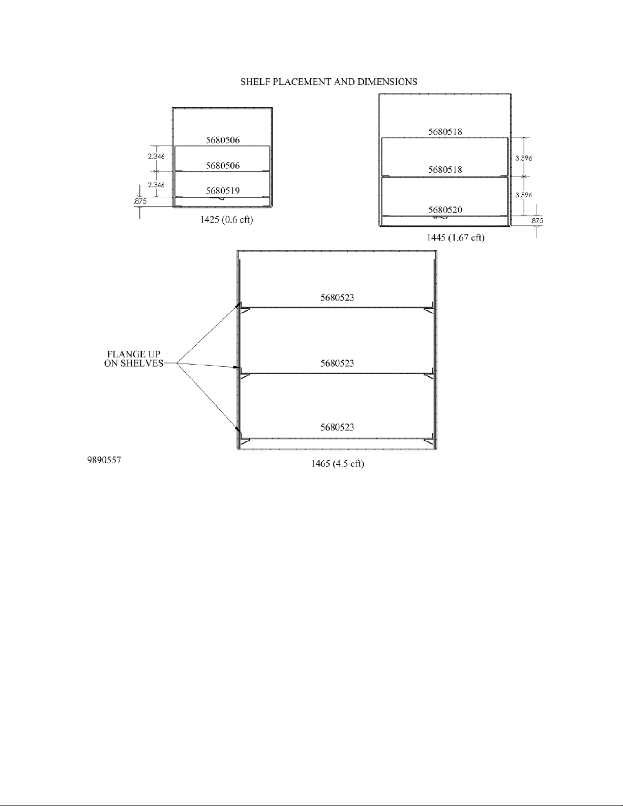
packaging before discarding. The model SVAC1 (1425) / SVAC1-2 (1425-2) is equipped with two (2) deep
shelves and one (1) shallow shelf. The model SVAC2 (1445) / SVAC2-2 (144-25)is equipped with two (2) deep
shelves, one (1) shallow shelf and four (4) adjustable feet. The model SVAC4 (1465) / SVAC4-2 (1465-2) is
equipped with three (3) shelves and four (4) adjustable feet.
Recording Data Plate Information
Once you have determined the unit is free from damage, locate the data plate at the back of the unit. The data plate
indicates your unit’s model number and serial number. Record this information below for future reference.
Table 1. Data Plate Information
Page 5
5
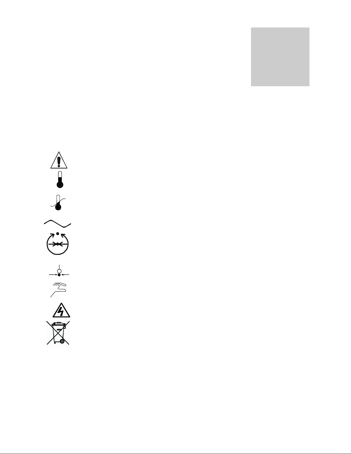
GRAPHIC SYMBOLS
Symbol
Identification
Indicates that you should consult your operator’s manual for further instructions.
Indique que l'opérateur doit consulter le manuel d'utilisation pour y trouver les instructions
complémentaires.
Indicates “Temperature”
Repère "température"
Indicates “Overtemperature Protection”
Signale un "dépassement de température"
Indicates “AC Power”
Repère "secteur AC"
Indicates "Vent Valve"
Indique “clapet de mise à l’air libre”
Indicates "Vacuum Gauge"
Indique “jauge de vide”
Indicates “Manually Adjustable”
Signale un élément "réglable manuellement"
Indicates “Potential Shock Hazard” behind partition
Signale un "risque potentiel d'électrocution" au-delà de la cloison.
Indicates “Unit should be recycled” (Not disposed of in land-fill)
Indique “l’appareil doit être recyclé“ (Ne pas jeter dans une décharge)
Section
Your oven has been provided with a display of graphic symbols which should help in identifying the use and function
of the available user adjustable components.
Page 6

6
INSTALLATION
Section
Local city, county, or other ordinances may govern the use of this equipment. If you have any questions about local
requirements, please contact the appropriate local agency. Installation may be performed by the end user.
Under normal circumstances these units are intended for use indoors, at room temperatures between 15 and 35C, at no
greater than 80% relative Humidity (at 25C) and with a supply voltage that does not vary by more than 10%. Installation
category is CAT-II Pollution Degree 2. Customer service should be contacted for operating conditions outside of these
limits.
3.1 Power Source: The unit power requirements are listed on the data plate. PLUG THE UNIT INTO A
3.2 Location: When selecting a site for the unit, consider conditions which may affect performance, such as heat
3.3 Lifting / Handling: These units are heavy and care should be taken to use appropriate lifting devices that are
3.4 Leveling: The unit must sit level and solidly. Models SVAC1 (1425) and SVAC1-2 (1425-2) have four (4) rubber
3.5 Cleaning: The unit chamber should be cleaned and disinfected prior to use. The operating conditions and
3.6 Shelves: See Figure below. Place items on shelves. DO NOT place items directly on the floor of the chamber.
PROPERLY GROUNDED AND RATED RECEPTACLE OF THE CORRECT STYLE. THE VOLTAGE OF THE
RECEPTACLE SHOULD NOT VARY MORE THAN 10% FROM THE DATA PLATE RATING. A separate
circuit is recommended for this unit to prevent loss of product due to overloading or circuit failures caused by
other equipment. Position the unit to allow user access to the power cord.
from radiators, ovens, autoclaves, etc. Avoid direct sun, fast-moving air currents, heating/cooling ducts, and
high-traffic areas. To ensure air circulation, allow a minimum of 30 cm between the unit and any walls or
partitions which might obstruct free air flow.
sufficiently rated for these loads. Units should only be lifted from their bottom surfaces. Doors, handles and
knobs are not adequate for lifting or stabilization. The unit should be completely restrained from tipping during
lifting or transport. All moving parts such as shelves and trays should be removed and doors need to be
positively locked in the closed position during transfer to prevent shifting and damage.
feet that are already attached to the unit and are not adjustable. Leveling feet are supplied with models SVAC2
(1445) / SVAC2-2 (144-25) and SVAC4 (1465) / SVAC4-2 (1465-2) and must be installed in the four holes at the
base of the unit. With the unit standing upright, turn the leveling feet counterclockwise to raise the level of that
corner. Adjust each foot until the unit stands solid and level. If the unit must be moved, turn the leveling feet in all
the way to prevent damage while moving.
appropriate protocol will determine the correct procedure for decontamination. A typical decontamination
procedure that is adequate for many situations has been described below. As well, certain steps are listed
that will help reduce the likelihood of contamination and the necessity of decontamination. Whatever
process is appropriate, it needs to be done on a regularly scheduled basis. Depending on usage and
protocol, this may be monthly, quarterly or otherwise. Regardless of the decontamination procedure used,
certain precautions will need to be taken:
A. Always disconnect the unit from the electrical service when cleaning.
Assure all volatile or flammable cleaners are evaporated and dry before reconnecting the unit to the
power supply.
B. Special care should be taken when cleaning around sensing heads to prevent damage.
C. Do not use chlorine-based bleaches or abrasive cleaners this will modify the stainless steel interior
finish. DO NOT USE hard tools such as metal wire brushes or steel wool. Use non-abrasive
cleaners and soft tools such as plastic brushes.
D. In the event hazardous material is spilled onto or into the equipment, appropriate decontamination
must be carried out. If there is any doubt about the compatibility of decontamination or cleaning
agents with parts of the equipment or with material contained, please contact the manufacturer or
his agent. No decontamination or cleaning agents should be used which could cause a hazard as a
result of a reaction with parts of the equipment or with the material contained in it.
Page 7
7
Page 8

8
PRECAUTIONS
Section
NOTE: THIS IS NOT AN EXPLOSION PROOF OVEN
4.1 The bottom surface of the chamber should not be used as a work surface.
4.2 Do not place or use explosive, combustible, or flammable materials in the oven.
4.3 Do not use sealed containers in the oven chamber.
4.4 Do not modify the power cord provided with the unit. If the plug goes not fit an outlet, have a proper outlet
installed by a qualified electrician.
4.5 Removal of any service panel or disconnect the unit from the electrical power source before attempting any
repairs or component replacements should be done by approved trained service personel..
4.6 If a mercury thermometer is used and breakage should occur, make sure all the spilled mercury is removed from
the chamber.
4.7 This oven is NOT suitable for use in Class I, II, or III locations as defined in the National Electric Code of the
United States of America, NFPA 70.
4.8 This oven is not intended, nor can it be used, as a patient connected device.
Page 9
9
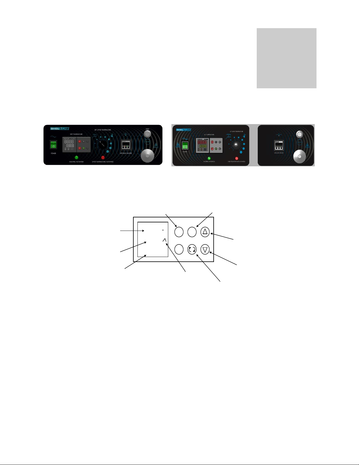
CONTROL PANEL OVERVIEW
SVAC1 (1425) & SVAC1-2 (1425-2)
SVAC2 (1445) & SVAC2-2 (1445-2)
SVAC4 (1465) & SVAC4-2 (1465-2)
Watlow EZ-Zone Control
20.0
20.0
RESE T
EZ1
EZ2
2
C
CURRENT OVEN CHAMBER
TEMPERATURE
TEMPERATURE SET
POINT (YOUR DESIRED
TEMPERATURE)
INDICATES THAT THE
CONTROLLER IS POWERING THE
OVEN’S HEATER
RAMPING SYMBOL INDICATES
THAT A HEATING PROFILE IS
RUNNING
THE ADVANCE KEY SCROLLS
THROUGH MENUS AND
PARAMETER LISTS
THE DOWN ARROW KEY
ADJUSTS SET POINTS OR
CHANGES PARAMETERS
THE UP ARROW KEY
ADJUSTS SET POINTS
OR CHANGES PARAMETERS
THE RESET KEY
SCROLLS 1 PAGE BACK
THE EASY ZONE KEY 1
INITIATES AND ENDS
HEATING PROFILES
Watlow Controller Details
On some older Watlow
Controllers the Reset
button may be labeled with
an infinite ∞ symbol rather
than RESET.
Section
5.1 POWER SWITCH: This is the main power I/O (On/Off) switch. It must be in the ON position before any
systems are operational.
5.2 MAIN TEMPERATURE CONTROL: Tthe Main Temperature control is a Watlow EZ-Zone Controller consisting
of the digital display and UP/DOWN arrow pads for adjusting set point temperatures and calibration, and four
buttons for setting programs and parameters.
5.3 HEATING LIGHT: This green indicator light is on whenever the MAIN TEMPERATURE CONTROL has
activated the heating elements to reach and maintain set point.
5.4 SET OVER TEMPERATURE: The Over Temperature Limit Control is completely independent of the MAIN
TEMPERATURE CONTROLLER and guards against malfunctions which would allow temperature to rise past
the Temperature set point. Setting adjustments for this control require a flat-edged tool to eliminate accidental
changes. The control has a dial that is marked gradient scale and is adjustable across this scale. If the
chamber temperature esxceeds over the set point, the Set Over Temperature will limit the rise to approximately
10C above the set point selected.
5.5 OVER TEMPERATURE LIGHT: This red indicator light is on whenever the temperature has exceeded the set
point of the Over Temperature Limit Control and has activated and taken control of the oven. Under normal
operating conditions this pilot light should never be on.
Page 10

10
5.6 FUSE: Mounted on the rear wall next to the power cord, provides protection for the unit’s electrical circuitry
against over current conditions. The fuse, when blown, must be replaced before the unit can continue operation.
Match the fuse ratings with those on the fuse data plate.
5.7 VACUUM: This adjustment handle allows opening and closing of the vacuum valve to an external vacuum
pump or system.
5.8 VENTILATION: This adjustment handle controls the amount of ventilation to the chamber as when using a
purge gas. This valve must be closed (completely clockwise) when the unit is in the vacuum mode.
5.9 VACUUM GAUGE: This digital gauge indicates the chamber operating vacuum. Your unit may be equipped
with either a SUNX or Autonics device.
See Appendix for instructions on how to set the “unit” scale.
Page 11

11
VACUUM OPERATION
Section
6.1 The vacuum pump is the heart of your vacuum oven system. The selection of a vacuum pump is critical to
match your overall performance expectations for time to evacuate the chamber and the maximum obtainable
vacuum levels. As well, the type of pump should be considered depending on the material that will be
placed in the chamber. Common types are Chemical Duty PTFE Dry, Standard Duty Dry, Compact DirectDrive, and other specialty pumps for Corrosive gases. Selection of application specific pumps can improve
the overall oven performance as the right pump ensures cost effectiveness and minimizes pump
maintenance.
In general, a dry pump with a pumping capacity of 100 l/min. can be used to evacuate 840 liters volume
(0.84 cubic meters) in a reasonable time. High vacuum pumps based on oil sealed rotary vane technology
use the rule of thumb of 1 to 1.5 times the volume of space to determine pumping capacity (300 liters
volume needs a 300 to 350 l/min. pump). The reason for the differing rule on oil sealed pumps is that the
evacuation needs to be below 10torr in less than 10-15 minutes to avoid poor lubrication and overheating
the internal pumping mechanism. Oil-free piston pumps don’t overheat while evacuating larger chambers;
however the time to maximum vacuum takes longer the smaller the pumping capacity.
6.2 IT IS IMPORTANT TO USE VACUUM TUBING FOR ALL THE VACUUM HOOKUPS. OTHER TYPES OF
TUBING MAY COLLAPSE AND PREVENT COMPLETE EVACUATION.
6.3 To Apply Vacuum to the Chamber:
There are two ways to apply vacuum.
1. Attach the hose from the vacuum pump to the 3/8" hose connection on back of the oven. Close the
VENTILATION valve (clockwise) and open the VACUUM valve. Latch the door shut and start the
vacuum pump. This action will hold the door shut and against the gasket until the pump creates a
vacuum in the chamber. Once a good vacuum seal is accomplished, the door will hold itself shut and
sealed until the chamber is returned to ambient atmospheric pressure.
2. The unit is equipped with a KF-25 flanged 1” port. This can be used for faster, higher volume vacuum
pump down. When the large port, close both the VENTILATION and VACUUM valves.
6.4 Watch the VACUUM GAUGE and when the required vacuum is obtained, close the vacuum valve and turn
pump off. The digital vacuum gauge is factory set to display inches of mercury. The display will show 0—29.92
inch. If the vacuum exceeds 29.92, the display will show “_ _ _”. The 0 indication represents present
atmospheric pressure. See Reference 2 for details for digital gauge settings.
6.5 Vacuum Release: To return the chamber to ambient atmospheric pressure, open the VACUUM valve very
slowly and allow the chamber to re-pressurize. The speed of pressurizing can be controlled by how much the
valve is opened.
Page 12

12
OVEN OPERATION
REFERENCE
THERMOMETER
PROCESS
DISPLAY
OFFSET
CAL
152°C
150°C 2 148°C
150°C
-2
Section
NOTE: When starting a new oven, allow the oven to operate two hours at 150˚C. Slight vapor or smoke may occur in
the initial heat-up. This is the dissipation of protective coatings that have been added to the oven elements.
7.1 Power Connection: Connect the service cord to a grounded outlet if supplied with a detachable cord set.
Switch the unit to the ON position.
7.2 Turn the Set Over Temperature control to its maximum position (clockwise).
7.3 Setting the Main Temperature Control
Video is also available for instructions “Quick Start-Shel lab Vacuum Oven Basics.”
http://www.shellab.com/store/virtual-tour-vac-oven.html
To set the main temperature controller, perform the following steps:
1. Turn the power switch to the ON position. The Power ON Light will illuminate along with the Watlow PM
Control.
2. Make sure the control is not running a program. If the Ramp Symbol is illuminated on the right side of the
display, that means there is a program running. To turn off the program, push the EZ Key once. The
Ramp Symbol should go off, indicating the program has ended. Enter the desired set point.
7.4 Calibrating the Main Temperature: It is recommended that calibration is done once the unit is installed in its working
environment. The unit should be stable at set point for several hours and under vacuum. Once unit has been stable for
several hours, compare process display with reference thermometer. After comparing the two figures out the
calibration offset by subtracting the reference thermometer reading to the display reading. If the reference is greater
than the display, it will be a positive number. If the reference is smaller than the display, it will be a negative number.
EXAMPLE:
Once the Offset Calibration Number is established, it can then be entered into the control. To enter into the
control, push and hold both UP and DOWN Arrow Button simultaneously for three (3) seconds or until A1
appears in the Upper Display and Oper appears in the Lower Display. Then, push the Advance Key
repeatedly unit I.CA appears in the Bottom Display and a number value in the Upper Display. This number
value can be changed by using the UP or DOWN Arrow Buttons. Change the number value to the Offset
Calibration Number established earlier. If it is a negative number, you subtract. If it is a positive number,
you add. Once the Offset Calibration Number is entered, push the Infinite Button repeatedly to exit to Home
Page. (Process Temperature Display Top and Set Point Display Bottom.)
Page 13

13
7.5 Setting the Set Over Limit Temperature Control:
To set the Over Temperature Limit Control, perform the following:
1. The Over Temperature Limit Control should be initially set to its maximum position to allow the Main
Temperature Controller to stabilize.
2. Set Main Temperature Control to 1˚C above desired set point and allow to stabilize.
3. Turn the Over Temperature Limit Control counter-clockwise until the Over Temperature Light just
activated. Then, slowly turn the knob clockwise until the light goes out.
4. Return the Main Temperature Control back to desired set point.
5. This should set the Over Temperature Limit Control 1˚C above Main Temperature Control. If the Over
Temperature feature is being used, it is should be tested annually.
7.6 Digital Vacuum Gauge Setup: See Reference Section of the manual.
7.7 Ramp and Soak Settings: The Watlow EZ-Zone Controller is capable of 40-step ramp and soak
profiles (or 40 different files-with 10 steps per file). The program will ramp up to 150˚ from ambient
condition and soak for 4 hours. For your programs, make sure enough time is entered in the ramp
time, so the oven can reach set point before entering the soak step. See Reference Section of the
manual for more information.
Video is also available for instructions “How to Program Ramp & Soak Profiles.”
http://www.shellab.com/store/virtual-tour-vac-oven.html
Page 14

14
MAINTENANCE
Section
Warning: Prior to any maintenance or service on this unit, disconnect the power cord from the power supply.
Before reattaching the unit to its power supply, be sure all volatile and flammable cleaners are
evaporated and dry.
Avertissement: Avant d'effectuer toute maintenance ou entretien de cet appareil, débrancher le cordon secteur
de la source d'alimentation. Avant de reconnecter l'appareil sur le secteur, s'assurer que tous
les produits de nettoyage volatiles et inflammables sont complètement évaporés.
Cleaning
The unit chamber should be cleaned and disinfected prior to use.
Periodic cleaning is required. To clean the incubator, perform the following steps:
1. Remove all of the interior parts, if assembled.
2. Clean the incubator with a mild soap and water solution, including all corners. DO NOT USE spray cleaners that
might leak through openings and cracks and get on electrical components, or that may contain solvents that will
harm coatings. DO NOT USE chlorine-based bleaches or abrasives, as they will damage the stainless steel
interior.
3. Rinse with distilled water and wipe dry with a soft cloth.
4. Special care should be taken when cleaning around the sensing heads to prevent damage.
Disinfecting
Disinfect the incubator on a regular basis. To disinfect the incubator, perform the following steps.
1. Remove all of the interior parts, if assembled.
2. Disinfect the incubator, including all corners and the access port, using a suitable disinfectant. Shelves and shelf
clips are autoclaveable. DO NOT USE spray disinfectants that might leak through openings and cracks and get
on electrical components, or that may contain solvents, corrosives, or abrasives that will harm the stainless steel
coatings. Special care should be taken when cleaning around sensing heads to prevent damage and around the
door gasket so as not to impair the positive seal.
3. If a hazardous material/substance has been spilled in the unit, immediately initiate your site’s Hazardous Material
Spill Containment protocol. Contact your local Site Safety Officer and follow instructions per the policy and
procedures established for your site.
4. There are many commercially available disinfectants available that are non-corrosive and non-abrasive and
suitable for use on stainless steel surfaces. Contact your local Site Safety Officer for detailed information for the
proper disinfectants suitable for your operation.
Warning: Never clean the unit with alcohol or flammable cleaners and assure all volatile or flammable cleaners
are evaporated and dry before reattaching the unit to the power supply.
Avertissement: Ne jamais nettoyer l'appareil à l'alcool ou avec des nettoyants inflammables et veiller à ce que
les produits volatils ou inflammables soient entièrement évaporés avant de rebrancher le
content d'alimentation de l'appareil.
Periodically inspect the door latch, trim, catch and gasket for signs of deterioration. Failure to maintain the integrity of
the door system will shorten the life span of the incubator.
No maintenance is required on electrical components. If the incubator fails to operate as specified, please review the
Troubleshooting Section prior to calling for service.
Page 15

15
TROUBLESHOOTING AND SERVICE
TEMPERATURE
Temperature too high
1/ controller set too high
2/ controller failed on–call Customer Service
3/ wiring error–call Customer Service
Display reads "HI" or "400"+
probe is unplugged, is broken or wire to sensor is broken–call Customer
Service
Chamber temperature spikes over
set point and then settles to set
point
Recalibrate to desired temperature set point
Temperature too low
1/ Set Over Temperature too low
2/ Main control set too low
3/ unit not recovered from door opening – wait for display to stop changing
4/ unit not recovered from power failure or being turned off
5/ element failure – see if Heating light is on
6/ Main controller failure – confirm with front panel lights that controller is
calling for heat
7/ Set Over Temperature failure – confirm with front panel lights Set Over
Temperature is operating correctly
8/ wiring problem–check all functions. If not solved-call Customer Service
Display reads "LO"
1/ if ambient room temperature is lower than range of unit–compare set points
and ambient temperature to rated specifications in section 9.0, Unit
Specifications.
2/ Main sensor is plugged in backwards–call Customer Service.
Unit will not heat over a temperature
that is below set point
1/ confirm that Set Over Temperature Control set point is set above the Main
Temperature set point.
2/ check calibration–using independent thermometer
Unit will not heat up at all
1/ verify that controller is asking for heat by looking for Heating light–if pilot
light is not on continuously during initial start up, there is a problem with the
controller-call Customer Service.
2/ do all controller functions work?
3/ is the Set Over Temperature Control set high enough?–for diagnostics,
should be fully clockwise with the Over Temperature light never on
4/ has the fuse blown? Check fuse at inlet.
5/ Units will need at least some vacuum in chamber to keep unit air tight-verify
with Vacuum Gauge is above “0”.
Indicated chamber temperature
unstable
1/ ± 1. may be normal.
2/ is ambient room temperature radically changing–either door opening or
room airflow from heaters or air conditioning ? –stabilize ambient conditions.
3/ calibration sensitivity–call Customer Service.
Section
Page 16

16
4/ Controller set too low–be sure that it is more than 5 degrees over desired
set point; check if Over Temperature light is on continuously; turn controller
knob completely clockwise to see if problem solved then follow instructions in
section 6.6 for correct setting.
5/ electrical noise–remove nearby sources of RFI including motors, arcing
relays or radio transmitters.
Will not maintain set point
1/ assure that set point is at least 5 degrees over ambient room temperature
2/ see if ambient room temperature is fluctuating
Display and Reference thermometer
don’t match
1/ calibration error-recalibrate.
2/ Main temperature sensor failure–evaluate if Heating light is operating
correctly
3/ Main controller failure–evaluate if Heating light is operating correctly
4/ allow at least two hours to stabilize
5/ verify that reference thermometer is certified
Can't adjust set points or calibration
1/ turn entire unit off and on to reset
2/ if repeatedly happens-call Customer Service
Calibrated at one temperature, but
not at another
This can be a normal condition when operating temperature varies widely. For
maximum accuracy, calibration should be done as close to the set point
temperature as possible.
MECHANICAL
Glass door not sealing
Check physical condition of gasket-replace if worn.
Outer door not sealing
1/ see if hinges are out of adjustment
2/ Confirm that unit has not been damaged and body out of square.
Oven won’t hold vacuum
1/ check door gasket for damage, wear or lack of compliance
2/ assure all vent and feed valves are closed tightly
3/ assure tight connections to pump
OTHER
Controller on at all times-"locked-up"
1/ turn unit off and on to reset
2/ if cannot change any condition on the front panel-call Customer Service
Wall fuse/circuit breaker is blown
1/ check wall power source
2/ see what other loads are on the wall circuit
Unit will not turn on
1/ check wall power source
2/ check fuse/circuit breaker on unit or in wall
3/ see if unit is on, e.g., heater, and just controller is off
4/ check all wiring connections, esp. around the on/off switch.
Unit is smoking–Out of box
This is common during initial operation. Put unit under vent and run at full
power for two hours.
Contamination in chamber
1/ see cleaning procedure in operator’s manual
2/ develop and follow standard operating procedure for specific application;
include definition of cleaning technique and maintenance schedule
SERVICE
If this product should require service, contact Customer Service (800) 322-4897 or tech@Shellab.com. If return of the
product is necessary, an authorization number must be obtained and the product shipped according to your
representative, to the proper service center. To insure prompt handling, the return authorization number should be
placed on the outside of the package or container. Make sure a detailed explanation of the reason for return is
enclosed with the item.
Page 17

17
PARTS LIST
Description
100-120V
220-240V
Controller Knob
4450506
4450506
Outer Door Glass
SVAC1 (1425) & SVAC1-2 (1425-2)
SVAC2 (1445) & 1445-2
SVAC4 (1465) & SVAC4-2 (1465-2)
3550522
3550521
3550523
3550522
3550521
3550523
Door Glass
SVAC1 (1425) & SVAC1-2 (1425-2)
SVAC2 (1445) & SVAC2-2 (1445-2)
SVAC4 (1465) & SVAC4-2 (1465-2)
3550542
3550540
3550586
3550542
3550540
3550586
Elements
SVAC1 (1425) SVAC1-2 (1425-2) sides
SVAC1 (1425) SVAC1-2 (1425-2) bottom
SVAC2 (1445) SVAC2-2 (1445-2)sides
SVAC2 (1445) SVAC2-2 (1445-2)bottom
SVAC4 (1465) & SVAC4-2 side/top
SVAC4 (1465) & SVAC4-2 bottom
SVAC4 (1465) & SVAC4-2 side w/ probe
9570867
9570860
9570843
9570858
9570883
9570884
9570912
9570867
9570860
9570843
9570858
9570883
9570884
9570912
EMI Filter, 10A
2800502
2800502
EMI Filter, 20A SVAC4 (1465)
2800503
N/A
Fuse, T16A 250V
3300513
3300513
Fuse Holder
3300501
3300501
Door Gasket SVAC1 & SVAC1-2
9X9 inch red silicon
3450630
3450630
Door Gasket SVAC2 & SVAC2-2
12 X 12 red silicon
3450707
3450707
Door Gasket SVAC4 & SVAC4-2
18 X 18 red silicon
3450719
3450719
I/O Switch
7850570
7850570
Pilot Light, green
4650554
4650554
Pilot Light, red
4650553
4650553
Power Cord
1800510
1800539 (US)
1800500 (EURO)
Probe
SVAC1 (1425), SVAC1-2 (1425-2)
SVAC4 (1465) & SVAC4-2 (1465-2)
SVAC2 (1445) & SVAC2-2 (1445-2)
6600519
6600519
6600536
6600519
6600519
6600536
Safety Controller
1750648
1750648
Section
10
Continued on next page
Page 18

18
Description
100-120V
220-240V
Temperature Controller (Watlow)
SVAC1 (1425) & SVAC1-2 (1425-2)
SVAC2 (1445) & SVAC2-2 (1445-2)
SVAC4 (1465) & SVAC4-2 (1465-2)
9660501
9660502
9660503
9660501
9660502
9660503
Vacuum Gauge (Digital) Sunx
7850583
7850583
Vacuum Gauge (Digital) Autonics
7850584
7850584
Ventilation Valve
9990736
9990736
Vacuum Valve
9990737
9990737
Page 19

19
UNIT SPECIFICATIONS
Weight
Shipping
Net
SVAC1 (1425)
SVAC1-2 (1425-2)
145 lbs.
65.771 kg
105 lbs.
47.627 kg
SVAC2 (1445)
SVAC2-2 (1445)-2
220 lbs.
99.790 kg
179 lbs.
81.193 kg
SVAC4 (1465)
SVAC4-2 (1465-2)
400 lbs.
181.44 kg
360 lbs.
163.29 kg
Dimensions
Exterior W x D x H
Interior W x D x H
SVAC1 (1425)
SVAC1-2 (1425-2)
18 x 23 x 23.5 (in)
45.72 x 58.42 x 69.69 (cm)
9 x 20 x 9 (in)
22.86 x 30.48 x 22.86 (cm)
SVAC2 (1445)
SVAC2-2 (144-25)
20.5 x 39.50 x 26.25 (in)
52.07 x 77.47 x 66.68 (cm)
12 x 20 x 12 (in)
30.48 x 50.80 x 30.48 (cm)
SVAC4 (1465)
SVAC4-2 (1465-2)
26.5 x 34.5 x 32.25 (in)
67.31 x 87.63 x 81.92 (cm)
18 x 24 x 18 (in)
45.72 x 60.96 x 45.72 (cm)
Capacity
Cubic Feet
Liter
SVAC1 (1425)
SVAC1-2 (1425-2)
.56
15.93
SVAC2 (1445)
SVAC2-2 (144-25)
1.67
47.19
SVAC4 (1465)
SVAC4-2 (1465-2)
4.5
127.43
Vacuum Specifications
Vacuum Range
In Hg (-3.0 to -29.9), kPa (-010 to -101), mbar (-101 to -1010)
Display Vacuum range
(Display Resolution)
In Hg (0 to 29.9), kPa (5 to -101, mbar (0.05 to -1.013)
-29.92 inches Hg
10 mtorr
Maximum Permitted
END Vacuum
10 mtorr
Leak Rate
10 mtorr/hour
Temperature
Range
Stability
All Models
Amb. +10 to 220C
.2C
MODEL
VOLTS
AMPS
CYCLE
SVAC1 (1425)
SVAC1-2 (1425-
2)
110-120 VAC
7.0 A
50/60hz
220-240 VAC
4.5 A
50/60hz
SVAC2 (1445)
SVAC2-2 (1445-
2)
110-120 VAC
10 A
50/60hz
220-240 VAC
5.5 A
50/60hz
SVAC4 (1465)
SVAC4-2 (1465-
2)
110-120 VAC
13 A
50/60hz
220-240 VAC
7.0 A
50/60hz
Page 20

20
T2
S2
R2
T1
S1
R1
X1
W1
Y1
L2
K2
L3
K3
J3
L4
K4
98
99
CF
CD
CE
B5
D6
D5
2800502
EMI FILTER
3 4
2 1
1
2
4
1
2
4
INLET
4200513
FUSE
FAN
4880550
SOLID STATE
RELAY
7030533
OTP INDICATOR
4450553
HEATING INDICATOR
4450554
TOP ½ OF
OTP
1750648
BOTTOM ½ OF
OTP
1750648
LEFT ELEMENT 50.5Ώ
BOTTOM ELEMENT 67.7Ώ
RIGHT ELEMENT 50.5Ώ
TOTAL RESISTANCE
18.4Ώ = 750W @ 120V
BLACK HT
RED HT
BLACK HT
BLACK
HT
RED HT
RED HT
RED HT
RED HT
RED HT
RED HT
RED HT
BLACK HT
BLACK HT
BLACK HT
BLACK HT
BLACK HT
BLACK HT
BLACK HT
RED HT
TAN ULTRA HT
TAN ULTRA HT
TAN ULTRA HT
TAN ULTRA HT
BLACK BLACK
GREEN LIGHTED SWITCH 7850570
WATLOW PM
9660501
RED
WHITE
MODE
12VDC
POWER
SUPPLY
VACUMM GAGE
7850583
BROWN
BLUE
TC THERMOCOUPLE
6600519
6750507
TAN ULTRA HT
260°C HI
LIMIT
1750654
1 2 3 4 5
6 7 8 9
SUB D 9 PIN
CONNECTOR
1650537
WIRE DIAGRAM
SVAC1 (1425) 100-120V
9851330
Page 21

21
WIRE DIAGRAM
T2
S2
R2
T1
S1
R1
X1
W1
Y1
L2
K2
L3
K3
J3
L4
K4
98
99
CF
CD
CE
B5
D6
D5
2800502
EMI FILTER
3 4
2 1
1
2
4
1
2
4
INLET
4200513
FUSEFUSE
FAN
4880551
SOLID STATE
RELAY
7030533
OTP INDICATOR
4450553
HEATING
INDICATOR
4450554
TOP ½ OF
OTP
1750648
BOTTOM ½ OF
OTP
1750648
LEFT ELEMENT 20.5Ώ BOTTOM ELEMENT 15.4Ώ RIGHT ELEMENT 20.5Ώ
TOTAL RESISTANCE 56.4Ώ = 1000W @ 240V
BLACK HT
RED HT
BLACK HT
BLACK
HT
RED HT
RED HT
RED HT
RED HT
RED HT
RED HT
RED HT
BLACK HT
BLACK HT
BLACK HT
BLACK HT
BLACK HT
BLACK HT
BLACK HT
RED HT
TAN ULTRA HT
TAN ULTRA HT
TAN ULTRA HT TAN ULTRA HT
BLACK BLACK
GREEN LIGHTED SWITCH 7850570
WATLOW PM
9660501
RED
WHITE
MODE
12VDC
POWER
SUPPLY
VACUMM GAGE
7850583
BROWN
BLUE
TC THERMOCOUPLE
6600519
6750507
BLACK
WHITE
TAN ULTRA HT
260°C HI
LIMIT
1750654
1 2 3 4 5
6 7 8 9
SUB D 9 PIN
CONNECTOR
1650537
SVAC1-2 (1425-2) 220-240V
9851329
Page 22

22
T2
S2
R2
T1
S1
R1
X1
W1
Y1
L2
K2
L3
K3
J3
L4
K4
98
99
CF
CD
CE
B5
D6
D5
2800502
EMI FILTER
3 4
2 1
1
2
4
1
2
4
INLET
4200513
FUSE
FAN
4880550
SOLID STATE
RELAY
7030533
OTP INDICATOR
4450553
HEATING INDICATOR
4450554
TOP ½ OF
OTP
1750648
BOTTOM ½ OF
OTP
1750648
BLACK HT
RED HT
BLACK HT
BLACK
HT
RED HT
RED HT
RED HT
RED HT
RED HT
RED HT
RED HT
BLACK HT
BLACK HT
BLACK HT
BLACK HT
BLACK HT
BLACK HT
BLACK HT
RED HT
TAN ULTRA HT
TAN ULTRA HT
BLACK BLACK
GREEN LIGHTED SWITCH 7850570
WATLOW PM
9660502
RED
WHITE
MODE
12VDC
POWER
SUPPLY
VACUMM GAGE
7850583
BROWN
BLUE
TC THERMOCOUPLE
6600519
6750507
TAN ULTRA HT
260°C HI
LIMIT
1750654
LEFT ELEMENT 27Ώ
RIGHT ELEMENT 27Ώ
BOTTOM ELEMENT 180Ώ
TOTAL
RESISTANCE
11.7Ώ
TAN ULTRA HT
TAN ULTRA HT
TAN ULTRA HT
TAN ULTRA HT
TAN ULTRA HT
BOTTOM ELEMENT 180Ώ
TAN ULTRA HT
TAN ULTRA HT
1 2 3 4 5
6 7 8 9
SUB D 9 PIN
CONNECTOR
1650537
WIRE DIAGRAM
SVAC2 (1445) 100-120V
9851328
Page 23

23
T2
S2
R2
T1
S1
R1
X1
W1
Y1
L2
K2
L3
K3
J3
L4
K4
98
99
CF
CD
CE
B5
D6
D5
2800502
EMI FILTER
3 4
2 1
1
2
4
1
2
4
INLET
4200513
FUSEFUSE
FAN
4880551
SOLID STATE
RELAY
7030533
OTP INDICATOR
4450553
HEATING
INDICATOR
4450554
TOP ½ OF
OTP
1750648
BOTTOM ½ OF
OTP
1750648
BLACK HT
RED HT
BLACK HT
BLACK
HT
RED HT
RED HT
RED HT
RED HT
RED HT
RED HT
RED HT
BLACK HT
BLACK HT
BLACK HT
BLACK HT
BLACK HT
BLACK HT
BLACK HT
RED HT
BLACK BLACK
GREEN LIGHTED SWITCH 7850570
WATLOW PM
9660502
RED
WHITE
MODE
12VDC
POWER
SUPPLY
VACUMM GAGE
7850583
BROWN
BLUE
TC THERMOCOUPLE
6600519
6750507
BLACK
WHITE
260°C HI
LIMIT
1750654
LEFT ELEMENT 27Ώ RIGHT ELEMENT 27Ώ
BOTTOM ELEMENT 180Ώ
TOTAL
RESISTANCE
45.4Ώ
TAN ULTRA HT
TAN ULTRA HT
TAN ULTRA HT
TAN ULTRA HT
BOTTOM ELEMENT 180Ώ
TAN ULTRA HT
TAN ULTRA HT
TAN ULTRA HT
1 2 3 4 5
6 7 8 9
SUB D 9 PIN
CONNECTOR
1650537
WIRE DIAGRAM
SVAC2-2 (144-25)220-240V
9851327
Page 24

24
T2
S2
R2
T1
S1
R1
X1
W1
Y1
L2
K2
L3
K3
J3
L4
K4
98
99
CF
CD
CE
B5
D6
D5
2800503
EMI FILTER
3 4
2 1
1
2
4
1
2
4
INLET
4200513
FUSE
FAN
4880550
SOLID STATE
RELAY
7030533
OTP INDICATOR
4450553
HEATING INDICATOR
4450554
TOP ½ OF
OTP
1750648
BOTTOM ½ OF
OTP
1750648
BLACK HT
RED HT
BLACK HT
BLACK
HT
RED HT
RED HT
RED HT
RED HT
RED HT
RED HT
RED HT
BLACK HT
BLACK HT
BLACK HT
BLACK HT
BLACK HT
BLACK HT
BLACK HT
RED HT
TAN ULTRA HT
BLACK BLACK
GREEN LIGHTED SWITCH 7850570
WATLOW PM
9960503
RED
WHITE
MODE
12VDC
POWER
SUPPLY
VACUMM GAGE
7850583
BROWN
BLUE
TC THERMOCOUPLE
6600519
6750507
TAN ULTRA HT
260°C HI
LIMIT
1750654
TOTAL
RESISTANCE
9 Ώ
TOP ELEMENT 19.9Ώ
TOP ELEMENT 19.9Ώ
UPPER LEFT ELEMENT 13.5Ώ
UPPER RIGHT ELEMENT 13.5Ώ
BOTTOM ELEMENT 34Ώ
BOTTOM ELEMENT 34Ώ
LOWER LEFT ELEMENT 13.5Ώ
LOWER RIGHT ELEMENT 13.5Ώ
TAN ULTRA HT
TAN ULTRA HT
TAN ULTRA HT
TAN ULTRA HT
TAN ULTRA HT
TAN ULTRA HT
TAN ULTRA HT
TAN ULTRA HT
TAN ULTRA HT
TAN ULTRA HT
TAN ULTRA HT
TAN ULTRA HT
TAN ULTRA HT
1 2 3 4 5
6 7 8 9
SUB D 9 PIN
CONNECTOR
1650537
WIRE DIAGRAM
SVAC4 (1465) 100-120V
9851326
Page 25

25
T2
S2
R2
T1
S1
R1
X1
W1
Y1
L2
K2
L3
K3
J3
L4
K4
98
99
CF
CD
CE
B5
D6
D5
2800502
EMI FILTER
3 4
2 1
1
2
4
1
2
4
INLET
4200513
FUSEFUSE
FAN
4880551
SOLID STATE
RELAY
7030533
OTP INDICATOR
4450553
HEATING
INDICATOR
4450554
TOP ½ OF
OTP
1750648
BOTTOM ½ OF
OTP
1750648
BLACK HT
RED HT
BLACK HT
BLACK
HT
RED HT
RED HT
RED HT
RED HT
RED HT
RED HT
RED HT
BLACK HT
BLACK HT
BLACK HT
BLACK HT
BLACK HT
BLACK HT
BLACK HT
RED HT
BLACK BLACK
GREEN LIGHTED SWITCH 7850570
WATLOW PM
9660503
RED
WHITE
MODE
12VDC
POWER
SUPPLY
VACUMM GAGE
7850583
BROWN
BLUE
TC THERMOCOUPLE
6600519
6750507
BLACK
WHITE
260°C HI
LIMIT
1750654
TAN ULTRA HT
UPPER LEFT ELEMENT 13.5Ώ UPPER RIGHT ELEMENT 13.5Ώ
BOTTOM ELEMENT 34Ώ
TOTAL
RESISTANCE
36Ώ
TAN ULTRA HT TAN ULTRA HT
BOTTOM ELEMENT 34Ώ
TAN ULTRA HT
TAN ULTRA HT TAN ULTRA HTTAN ULTRA HT
TAN ULTRA HT
TAN ULTRA HT
LOWER LEFT ELEMENT 13.5Ώ LOWER RIGHT ELEMENT 13.5Ώ
TOP ELEMENT 19.5Ώ TOP ELEMENT 19.5Ώ
TAN ULTRA HT
1 2 3 4 5
6 7 8 9
SUB D 9 PIN
CONNECTOR
1650537
WIRE DIAGRAM
SVAC4-2 (1465-2) 220-240V
9851325
Page 26

26
REFERENCE 1
PROGRAMING RAMP AND SOAK PROFILE
THE WATLOW EZ ZONE CONTROLER IS CAPABLE OF 40 STEP RAMP AND SOAK PROFILES OR 4 DIFFERENT FILES WITH 10
STEPS PER FILE. BELOW IS A SIMPLE EXAMPLE PROGRAM ON HOW TO ENTER A PROFILE AND START AND RUN A PROGRAM.
THE PROGRAM WILL RAMP UP TO 150 DEGREES FROM AMBIENT CONDITION AND SOAK FOR 4 HOURS. FOR YOUR PROGRAMS,
MAKE SURE ENOUGH TIME IS ENTERED IN THE RAMP TIME SO THE OVEN CAN REACH SET POINT BEFORE ENTERING THE SOAK
STEP. FOR EXAMPLE: IF THE OVEN TAKES 1 HOUR TO HEAT UP TO 150 DEGREES AND YOU ENTER A RAMP TIME OF 30 MINUTES
IT WILL CUT DOWN THE SOAK TIME BY 30 MINUTES.
20.0
20.0
HOW TO ENTER THE PROGRAM
HOME PAGE
PUSH FOR
3
SECONDS
OR UNTIL
NEXT SCREEN
APEARS
P1
ProF
PUSH ONCE
FOR NEXT
SCREEN
1
P1
PUSH ONCE
S.tyP
FOR NEXT
BOTTOM
DISPLAY
S.tyP
t
USE UP
OR DOWN
ARROWS
TO SELECT
ti IN TOP
DISPLAY
PUSH ONCE
FOR NEXT
SCREEN
PUSH ONCE
FOR NEXT
BOTTOM
DISPLAY
t.SPl
USE UP
OR DOWN
ARROWS
TO SELECT
150 IN TOP
DISPLAY
t.SPl
SET POINT
VALUE
150
hoUr
# VALUE
USE UP
OR DOWN
ARROWS
TO SELECT
1 IN TOP
DISPLAY
hoUr
1
PUSH ONCE
FOR NEXT
SCREEN
Min
# VALUE
USE UP
OR DOWN
ARROWS
TO SELECT
0 IN TOP
DISPLAY
Min
0
PUSH ONCE
FOR NEXT
SCREEN
SEC
# VALUE
USE UP
OR DOWN
ARROWS
TO SELECT
0 IN TOP
DISPLAY
SEC
0
PUSH ONCE
TO RETURN
TO NEXT
SCREEN
1
P1
USE UP
OR DOWN
ARROWS
TO SELECT
2 IN TOP
DISPLAY
2
P1
PUSH ONCE
S.tyP
FOR NEXT
BOTTOM
DISPLAY
NEXT PAGE
Page 27

27
REFERENCE 1 (cont.)
USE UP
OR DOWN
ARROWS
TO SELECT
SOAh IN TOP
DISPLAY
S.tyP
SoAh
PUSH ONCE
FOR NEXT
SCREEN
hoUr
# VALUE
USE UP
OR DOWN
ARROWS
TO SELECT
4 IN TOP
DISPLAY
hoUr
4
PUSH ONCE
FOR NEXT
SCREEN
Min
# VALUE
USE UP
OR DOWN
ARROWS
TO SELECT
0 IN TOP
DISPLAY
Min
0
PUSH ONCE
FOR NEXT
SCREEN
SEC
# VALUE
USE UP
OR DOWN
ARROWS
TO SELECT
0 IN TOP
DISPLAY
SEC
0
PUSH ONCE
TO RETURN
TO NEXT
SCREEN
2
P1
USE UP
OR DOWN
ARROWS
TO SELECT
3 IN TOP
DISPLAY
3
P1
PUSH ONCE
S.tyP
FOR NEXT
BOTTOM
DISPLAY
USE UP
OR DOWN
ARROWS
TO SELECT
END IN TOP
DISPLAY
S.tyP
END
PUSH ONCE
FOR NEXT
BOTTOM
DISPLAY
END
USE UP
OR DOWN
ARROWS
TO SELECT
USEr IN TOP
DISPLAY
END
USEr
PUSH REPEATLY
TO
RETURN TO
HOME PAGE
20.0
20.0
TO START THE PROGRAM PUSH THE EZ1 BUTTON ONCE. A RAMP SYMBOL WILL APPEAR ON THE RIGHT SIDE OF THE DISPLAY
INDICATING THAT THE PROGRAM IS RUNNING. TO STOP THE PROGRAM PUSH THE EZ1 BUTTON AGAIN AND THE RAMP SYMBOL
WILL DISAPPEAR AND THE SET POINT WILL RETURN TO SET VALUE BEFORE STARTING PROGRAM. WHEN PROGRAM HAS
COMPLETED IT WILL AUTOMACTICALLY RETURN TO ORIGINAL SET PONT VALUE BEFORE PROGRAM STARTED. UNITS
EQUIPPED WITH POWER EXHAUST OUTLETS THE OUTLET WILL BE ACTIVE WHEN PROGRAMS ENDS.
PUSH ONCE
FOR NEXT
BOTTOM
DISPLAY
on
Ent 1
USE UP
OR DOWN
ARROWS
TO SELECT
on IN TOP
DISPLAY
oFF
Ent 1
THIS SECTION IS ONLY FOR UNITS THAT IS
EQUIPPED WITH POWER EXHAUST OUTLET
Page 28
28
REFERENCE 1 (cont.)
150
125
100
75
50
25
0
1 2 3
4
5
6 7
HOURS
DEGREES C
175
8
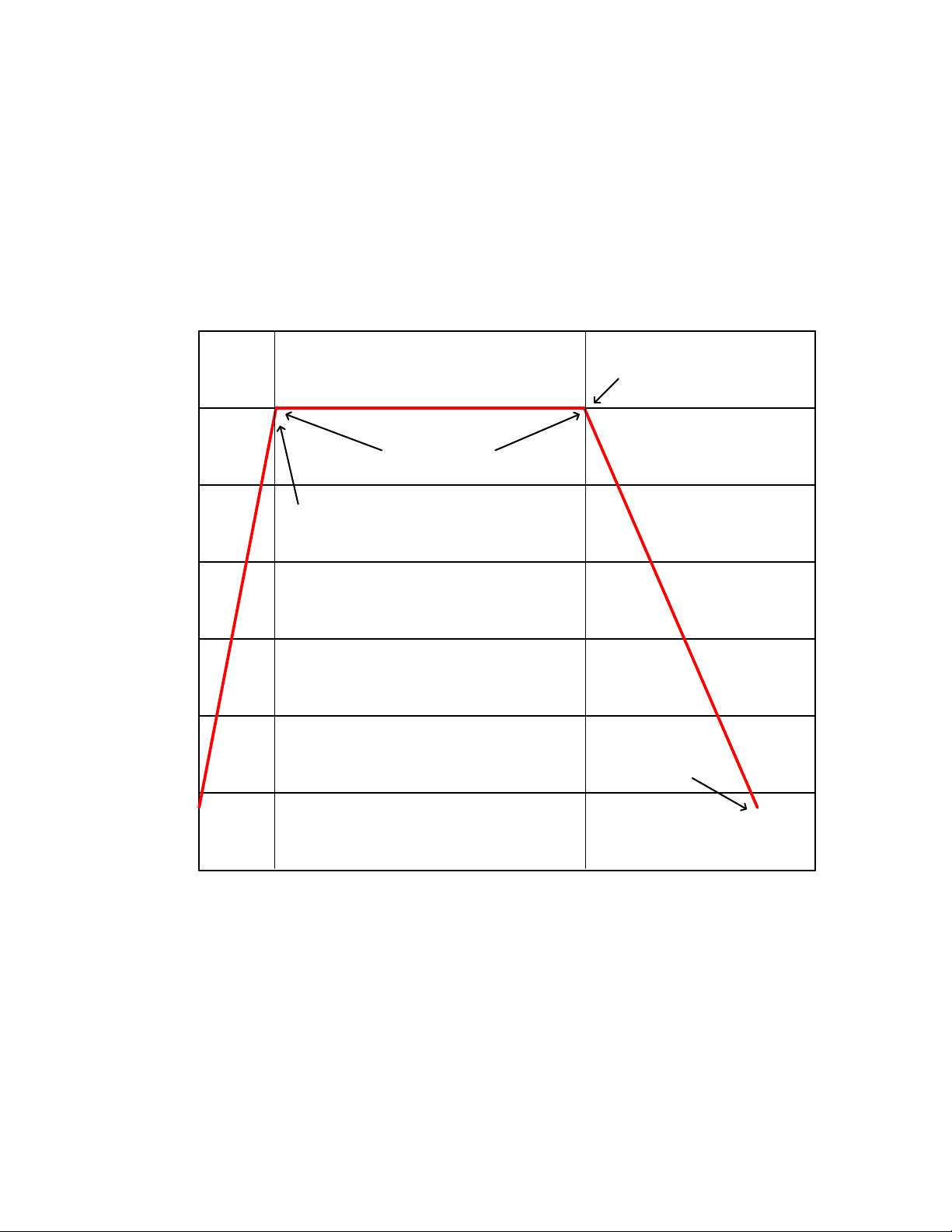
EXAMPLE GRAPH OF PROGRAMED PROFILE
WITH 1 HOUR TIME TO TEMPERATURE AND 4
HOURS SOAK AT TEMPERATURE
TI= 1 HOUR
RAMPTIME TO
SET POINT
SOAh=4 HOURS
SOAK TIME AT
TEMPERATURE
NATURAL
COOL DOWN
TO USER SET
POINT
COOL DOWN
TIME WILL
VERY DEPENDING ON
OVEN SIZE AND
CONSTRUCTION
UNITS WITH POWER
EXHAUST OUTLETS
WILL ACTIVATE HERE
Page 29

29
REFERENCE 2
UNITS
VACUUM
DISPLAY
LETTER
KPA
P
KGF/CM2
J
BAR
b
PSI
S
MMHG
H
INHG
I
FIRST
DIGIT
SECOND
DIGIT
THIRD
DIGIT
d d I
SUNX VACUUM GAUGE
ZERO ADJUSTMENT: The SUNX DP2-20F vacuum gauge comes preset from the factory reading vacuum in inhg
and automatically runs in sensing mode when powered on. At different altitudes the gauge may need to be rezeroed. Without pressure applied and vacuum door open exposing the gauge to atmospheric pressure it should read
0.0. If not, zero the gauge by pressing and holding both up and down arrows simultaneously until the display reads
zero then release the buttons and it should return to sensing mode automatically and read zero.
CHANGING VACUUM SCALES: The vacuum gauge can be set to indicate in several different units of vacuum.
Below is a list of the different units of vacuum that can be selected with the corresponding display code.
The setup parameters are identified in by a three digit letter code. The first digit represents analog or digital. The
second digit determines the output settings. The third digit determines the vacuum unit scale.
EXAMPLE
To change the vacuum units, press the mode button while pressing the up arrow button until the display reads Idd
where the first digit d is flashing. Use the up arrow key to scroll trough each digit until the I digit is flashing. Select
vacuum unit scale from the list above and change the display letter that corresponds to the vacuum units by pressing
the down arrow. After the correct display letter is chosen press the mode key once to return to sensing mode.
Changing the first and second digit letter will effect the way the vacuum gage functions and should be left reading dd.
SETTING OUTPUTS: The vacuum gauge comes with two outputs. These outputs are not used and are not hooked
up to do anything. The gauge is used to indicate vacuum only. To set the outputs so the LED light indicator will not
activate on the gauge press the mode key (MODE) once and the display should flash between P-1 and a value.
Press the up arrow until the display reads UP and then press the mode key (MODE) once and the display should
flash between P-2 and a value. Press the up arrow key until the display reads UP and then press the mode key
(MODE) once to return to sensing mode.
Page 30

30
REFERENCE 2 (cont.)
UNITS
VACUUM
DISPLAY
KPA
PA
KGF/CM2
UGF
BAR
BAR
PSI
PSI
MMHG
AAH
INHG
I NG
MMH2O
H2O
FACTORY SETUP
PARAMETERS
UNIT
INH
OUT
F---3
SPD
2.5
A-1
0.0
A-5
29.9
UNL
PEY
AUTONICS VACUUM GAUGE
ZERO ADJUSTMENT: The AUTONICS PSA-V01 vacuum gage comes preset from the factory reading vacuum in
inhg and automatically runs in sensing mode when powered on. Do to different altitudes the gage may need to be
zeroed. Without pressure applied and vacuum door open exposing the gauge to atmospheric pressure it should read
0.0. If not zero the gauge by pressing and holding both up and down arrows simultaneously until the display reads
zero than release the buttons and it should return to sensing mode automatically and read zero.
SETTING OUTPUTS: The vacuum gauge comes with two outputs. These outputs are not used and are not hooked
up to do anything. The gauge is used to indicate vacuum only. To set the outputs so the LED light indicator will not
activate on the gauge press the mode key (M) once and the display should flash between ST1 and a value. Press the
up arrow until the display reads HI and then press the mode key (M) once and the display should flash between ST1
and a value. Press the up arrow key until the display reads HI and then press the mode key (M) once to return to
sensing mode.
CHANGING VACUUM SCALES: The vacuum gauge can be set for several different units of vacuum. Below is a list
of the different units of vacuum that can be chosen from. And there corresponding display code.
To change the units of vacuum press and hold the mode (M) button for three seconds or until the display flashes
between unit and vacuum unit scale code. Press the up or down arrow to change the vacuum unit scale code. To exit
press and hold the mode (M) key for 3 seconds or until returned to sensing mode.
Page 31

31
REFERENCE 3
Altitude Above
Sea Level (Feet)
Altitude Above
Sea Level
(Meters)
Atmospheric
Pressure (psi)
Maximum Vacuum
Level
Attainable (inches
Hg)
Vacuum Level
Loss at
Altitude
Maximum Vacuum
Level
Possible at this
Altitude
0’
0 M
14.70 psi
29.921” Hg
-
-
1000’
305 M
14.16 psi
28.9” Hg
3.4%
96.6%
2000’
610 M
13.66 psi
27.8” Hg
7.1%
92.9%
3000’
914 M
13.16 psi
26.8” Hg
10.4%
89.6%
4000’
1219 M
12.68 psi
25.8” Hg
13.8%
86.2%
5000’
1524 M
12.22 psi
24.9” Hg
16.8%
83.2%
6000’
1829 M
11.77 psi
24.0” Hg
19.8%
80.2%
7000’
2134 M
11.33 psi
23.1” Hg
22.8%
77.2%
8000’
2438 M
10.91 psi
22.2” Hg
25.9%
74.1%
9000’
2743 M
10.50 psi
21.4” Hg
28.6%
71.4%
10,000’
3048 M
10.10 psi
20.6” Hg
31.3%
68.7%
11,000’
3353 M
9.71 psi
19.8” Hg
33.9%
66.1%
12,000’
3658 M
9.34 psi
19.0” Hg
36.5%
63.5%
13,000’
3962 M
8.97 psi
18.3” Hg
39.0%
61.0%
14,000’
4267 M
8.62 psi
17.5” Hg
41.4%
58.6%
15,000’
4752 M
8.28 psi
16.9” Hg
43.6%
56.4%
APPENDIX
The Effect of Altitude (Atmospheric Pressure) on Maximum Attainable
Vacuum Level
The Maximum Possible Vacuum Attained is based on your Altitude. Basically, the higher you are the less vacuum
you can attain. Because free air is less dense at higher altitudes (i.e. lower atmospheric pressure) operation at these
higher altitudes has the effect of reducing the capacity and maximum vacuum levels attainable. In general flow is not
affected, just the maximum vacuum level attainable.
It is also important to consider the relationship between atmospheric pressure and altitude as it affects vacuum pump
performance.
Refer to the following table to correct for vacuum pump performance at various altitudes.
Vacuum Gauge Reading When Read at Altitude
 Loading...