

Page 1
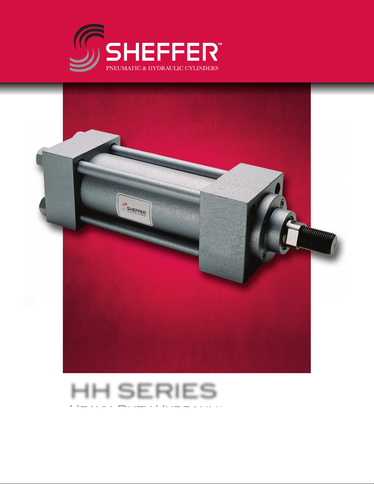
HH SERIES
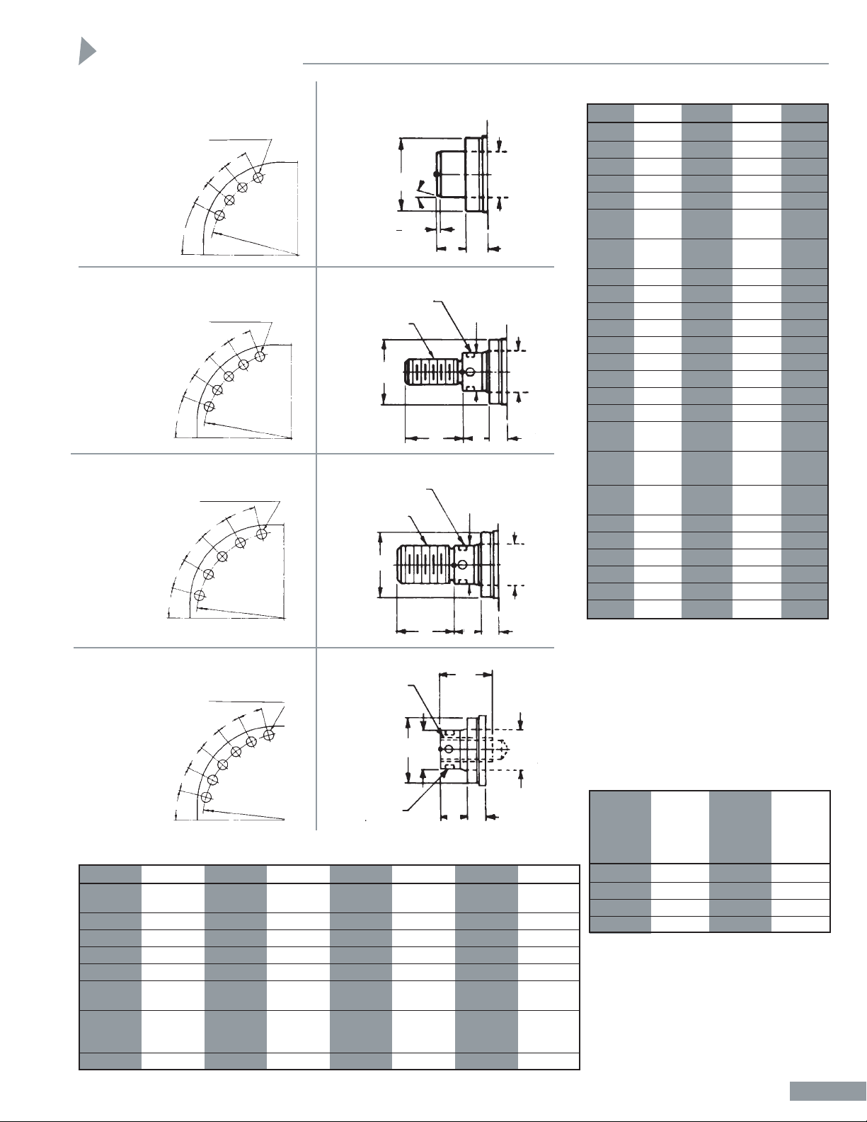
Heavy-Duty Hydraulic Cylinders
Pressure Rating 3,000 PSI
Page 2
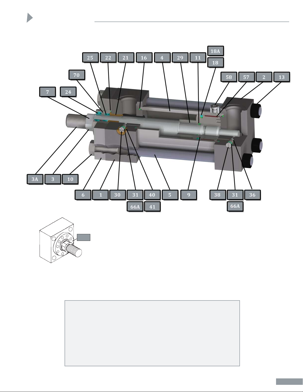
Piston rods through 4" diameter have a
minimum expected yield of 100,000 psi.
They are case hardened to 50 Rockwell C
to a depth of .030" for damage resistance.
They are then hard chrome plated for wear
and corrosion resistance. Larger diameter
rods have an expected minimum yield
of 50,000 to 60,000 psi depending on
diameter and are hard chrome plated.
Offers much longer fatigue life through
elimination of thread relief stress concentration point. Standard as Style 2 rod end on
all rod sizes through 2
1
/2" diameter. Studs
are pretorqued and locked in to prevent
loosening. They are machined from high
tensile steel and the threads rolled.
The steel tube is honed to an 8 to 16
microinch finish for low friction and long
seal and piston bearing life. Tube ends
are machined on the O. D. concentric with
the I. D. They are confined by the close
tolerance machining of the head and cap
which provides greater hoop strength.
Maximum strength is obtained through a
prestressed tie rod assembly.
Four wrench flats are provided as standard
for easy attachment. Spanner holes, in lieu
of flats, are standard on large diameter rods.
All pistons are machined from a fine grain
alloy cast iron. They are threaded directly
onto the piston rod, torqued, sealed and
locked in place with one or more set
screws.
The special piston seal is an endless
glass filled Teflon material with an O-ring
expander. One or more (depending on
bore size) bronze filled Teflon bearing
strips are also employed on this type piston
to eliminate metal-to-metal contact. This
type piston offers long life, low friction,
near zero leakage, and great tolerance for
side loading. It can be used successfully
on virtually any application.
Pressure activated O-ring seals are used
at rod gland and tube ends. Located to
eliminate extrusion and to provide positive
leak tight seal.
High load bearing bronze piloted into the
head. Located inboard of the seals to insure
a well lubricated bearing for the fastest
cycling applications. It need not be
removed for rod seal replacement.
The polyurethane wiper is designed to
wipe off abrasive dust and contaminants
on the retract stroke to insure long life for
packings, rod bearing, and piston rod.
Where the rod will be exposed to gummy
materials such as road tar, a metallic rod
scraper is available.
The polyurethane rod seal has a unique
design which incorporates the optimum
sealing properties of a U configuration with
the elastomeric properties of a compressiontype seal. The polyurethane material was
selected for toughness, abrasion resistance,
and the ability to resist extrusion under
rough service conditions.
Cushion pistons (29) are tapered to provide
gradual deceleration and eliminate shock
upon entrance. The Adjusting Screw
with fine threads (30) provides a wide range
of adjustment.
When required, air bleeds are located
where they can be employed most
successfully – at the tube and head juncture.
The straight thread plugs are equipped
with metallic O-rings so they can be used
repeatedly with a good seal every time.
Easily removable for replacement of rod
seal and wiper. In most cases it is not
necessary to demount or disassemble the
cylinder. Easier to service since on removal
of the ductile iron gland, the piston rod
remains supported by the separate rod
bearing.
DIMENSIONALLY INTERCHANGEABLE TO MEET ANSI SPECIFICATIONS
Construction
ITEM QUANTITY
NUMBER
DESCRIPTION
REQUIRED
1 HEAD 1
2 CAP 1
3 PISTON ROD 1
3A “STUD – STYLE II THREAD THRU 2
1
/2" ROD DIA.” 1
4 TUBE 1
5 TIE ROD 4
6 ROD GLAND RETAINER 1
6A ROD GLAND & RETAINER – SINGLE PIECE 1
9 PISTON – SLIPPER SEAL TYPE 1
10 RETAINER SCREW 1
11 SEAL - PISTON I.D. ‡
13 TIE ROD NUT 4
16 † TUBE SEAL 2
18 † PISTON SEAL – SLIPPER SEAL TYPE 1
18 A† EXPANDER – FOR SLIPPER SEAL 1
21 † ROD BEARING 1
22 † ROD GLAND SEAL 1
24 † ROD WIPER 1
25 † ROD SEAL 1
29 CUSHION PISTON – FRONT **
30 CUSHION ADJ. SCREW – FRONT OR REAR
(CROSS SLOT) **
31 “SEAL – CUSHION ADJUSTING AND CUSHION
CHECK – FRONT OR REAR” **
36 CUSHION CHECK BALL – FRONT OR REAR **
38 CUSHION CHECK PLUG – FRONT OR REAR **
40 CUSHION ADJ. CAPTIVATOR – FRONT OR REAR **
41 SEAL - CUSHION ADJ. CAPTIVATOR –
FRONT OR REAR **
57 PISTON BEARING STRIP *
58 AIR BLEED PLUG **
66 A “BACK-UP WASHER – CUSHION ADJUST AND
CUSHION CHECK – FRONT OR REAR” **
70 ROD GLAND 1
3
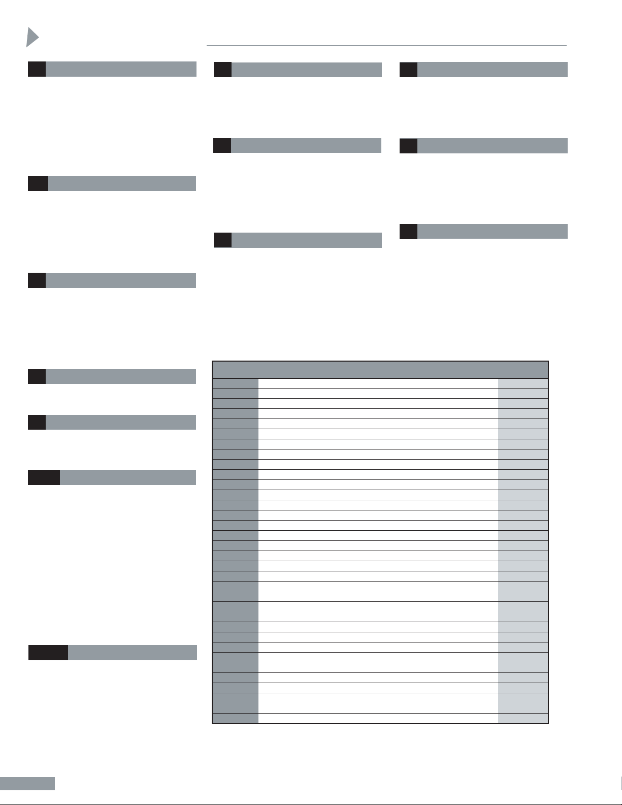
Piston Rod
4
Tube
5
Tie Rod Construction
7
Wrench Flats
9&18
Pistons & Piston Seals
21
Rod Bearing
24
Rod Wiper
25
Rod Seal
58
Air Bleeds (Optional)
70
Rod Gland
3A
Studded Rod End
Parts List
16, 22
Static Seals
29
Cushions
1
HH-1
‡Retainer Screws required varies by bore and mount
†Recommended Spare Parts
*One required thru 4" bore, 2 required 5" thru 8" bores, 3 required on 10" and 12" bores,
4 required on 14" bore.
**As required; specify if cushioned front, cushioned rear or cushioned both ends.
Page 3
Round, single piece rod gland
and retainer used on all but some
of the smaller bore sizes. Consult
pages on specific mounts.
1 1/8" THRU 24" BORE SIZES
Parts List
6A
Ordering Information:
Also see separate ordering information. When ordering parts, the
Model No. and Serial No. must be
specified. Give item no., name and
quantity of part desired. The Model
No. and Serial No. will be found on
a metal plate that has been drivescrewed to either the head or the
cartridge retainer.
Please Note:
Complete replacement packing kits
are available. For purposes of economy
and less down-time, it is recommended
that replacement packing kits be
stocked. They are described and priced
in the current Sheffer Replacement
Parts Price List and on CD Rom.
Contact your distributor or the factory
for these lists.
HH-2
Page 4
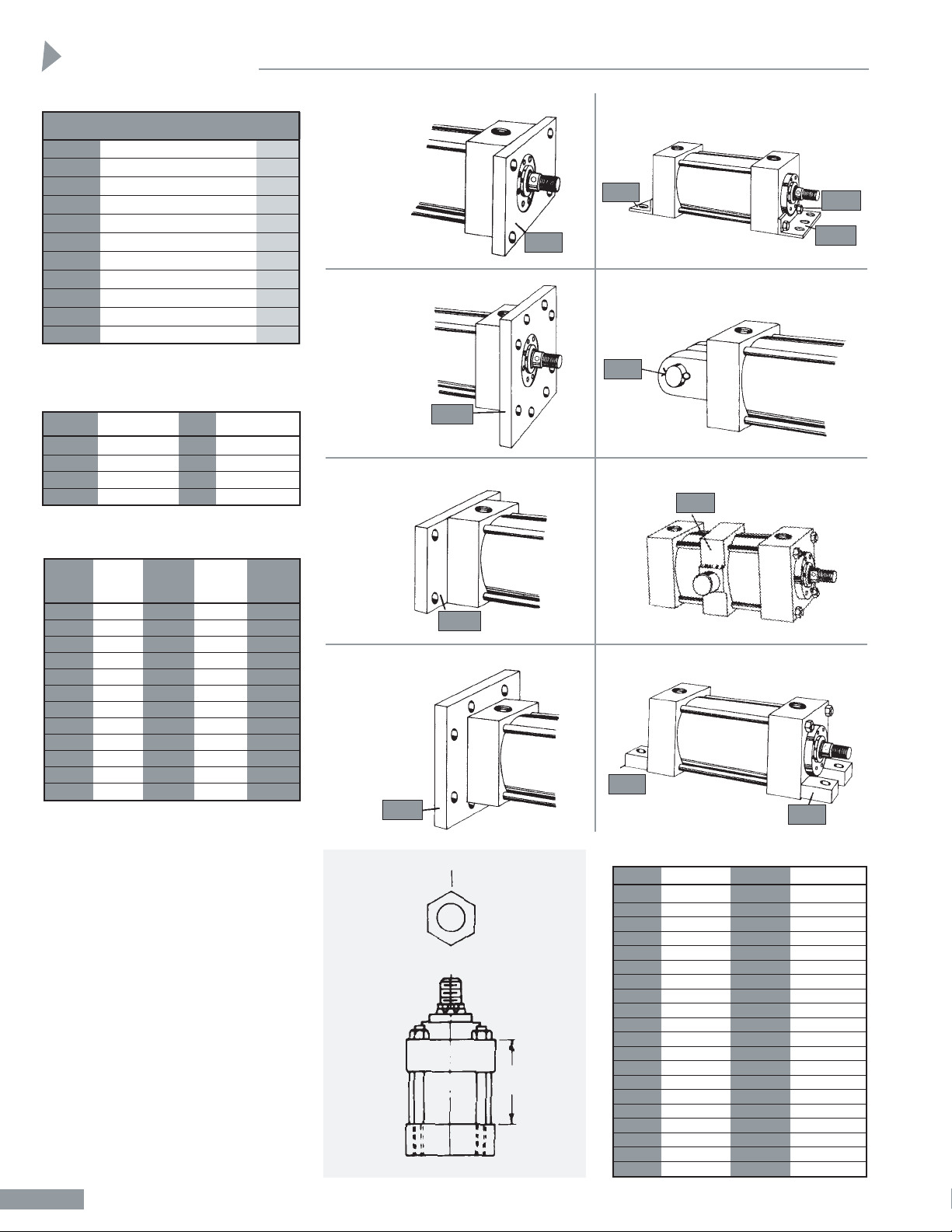
ITEM QTY.
NUMBER DESCRIPTION REQ'D
100 FRONT FLANGE 1
102 FRONT FLANGE EXTRA 1
103 REAR FLANGE 1
104 REAR FLANGE EXTRA 1
105 * FOOT BRACKET – FRONT 1
106 * FOOT BRACKET – SCREW 2
107 * FOOT BRACKET – REAR 1
112 CLEVIS PIN 1
117 INTERMEDIATE TRUNNION 1
108 * END LUG – FRONT 2
110 * END LUG – REAR 2
*Not available on 10", and larger bore cylinders.
FRONT FLANGE
MOUNT
STYLE FF
REAR FLANGE MOUNT
EXTRA SIZE
STYLE RFX
FRONT FLANGE MOUNT
EXTRA SIZE
STYLE FFX
FOOT BRACKET MOUNT
STYLE FB
INTERMEDIATE TRUNNION MOUNT
STYLE T
REAR FLANGE MOUNT
STYLE RF
CLEVIS MOUNT
STYLE C
END LUG MOUNT
STYLE
EL
100
107
102
112
103
104
110
108
106
105
117
Parts List
L
Scribe on Line Head
1
2
3
4
5
6
7
8
9
10
11
Screw Torque in Foot Pounds
BORE PISTON ROD HEX HEAD SOCKET HEAD
SIZE DIAMETER CAP SCREW CAP SCREW
11/8
5
/8 8
11/2 ALL 13.6
2 ALL 5
21/2 1, 13/8 5
21/2 1
3
/4
33
31/4 ALL 5
4 ALL 5
5 2, 21/2 5
5 3, 31/2 10
6 21/2 5
6 3, 31/2, 4 10
7 ALL 10
8 ALL 10
10 41/2, 5, 51/2 10
10 740
12 51/2 10
12 740
12 870
14 740
14 10 95
COLUMN 1 FULL 2 FULL 3 FULL
1 TURN TURNS TURNS
TURN (T) L PLUS T PLUS T PLUS T
IN 12THS LENGTH L LENGTH L LENGTH L LENGTH
1 23/4 361/2 70 1035/8
2 55/8 391/4 723/4 1061/2
3 81/2 42 755/8 1091/4
4 111/4 443/4 781/2 112
5 14 475/8 811/4 1143/4
6 163/4 501/2 84 1175/8
7 195/8 531/4 863/4 1201/2
8 221/2 56 895/8 1231/4
9 251/4 583/4 921/2 126
10 28 615/8 951/4 1283/4
11 303/4 641/2 98 1315/8
12 335/8 671/4 1003/4 1341/2
For 7" bore cylinders and larger, the tie
rods are given an initial torque, the tie
rods are heated, and then the tie rod
nuts are turned a calculated amount.
First torque all 4 tie rod nuts to 200-250
foot pounds. Measure the cylinder to
obtain length L, consult the chart for the
proper number of turns or fractions (in
12ths). The figures in Column 1 shown
in 12ths corresponds to the points and
flats of the hex nut (see illustration).
The piston rod of the cylinder should be
either fully retracted or fully extended
prior to heating. Place an asbestos sheet
between the tube and tie rod and heat to
800°F for as long a length as possible.
When the distance between the cylinder
heads is 18" or less, do not heat closer
than 3" of either head. Tie rods should
be heated and tightened in cross corner
rotation and in steps up to full tension.
Allow the tie rods to cool before testing
or installation.
Parts List
Tie Rod Torque for
1 1/8" through 6" Bores
TORQUE IN TORQUE IN
BORE FOOT POUNDS BORE FOOT POUNDS
11/8 8 31/4 110
11/2 30 4 130
2 50 5 325
21/2 50 6 480
Tie Rod Torque for
7" Bore and Larger
1
HH-3
Page 5
Cushions
Sheffer pioneered tapered cushions,
designed to provide gradual deceleration and eliminate shock upon entrance
of the cushion pistons, have now been
considerably improved. The tapered
cushion has been married with a fine
thread, wide range, adjusting screw.
This new combination offers a positive,
low-shock deceleration and a method to
adjust the cushioning effect for speeds
and loads.
The adjusting screw is identified by a
tag affixed to the head (or cap) and can
be further distinguished by the fact that
it is captivated with the Sheffer
exclusive captivator This allows full
open to close adjustment without
concern for damaging seals.
The cushion check, which does not
require adjustment, has a single slot in
its head. It does not project beyond the
surface of the head (or cap). The
cushion check plus the tapered cushion
piston provides rapid acceleration out
of cushioning. There is no spring in the
cushion check to fatigue, hence, no
worry of mechanical failure.
Cushioning is designed to properly
cushion the cylinder and is not
intended to cushion large inertia loads.
Cushions do not substitute for speed
controls or deceleration valves on most
installations.
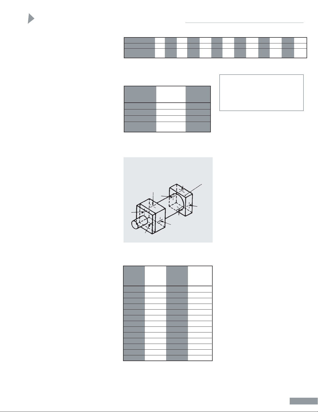
As indicated on page HH-6, the
standard positions for ports are 1 and 5.
Where possible, the standard positions
for cushion adjusting screws will be 2
and 6 and the standard positions for
cushion checks will be 4 and 8. With
some mounting styles, it is not possible
to so locate the adjusting screws and
checks. For example, a Trunnion Front
Mount has the trunnion pins located in
positions 2 and 4 on the head. With the
port in position 1, the only side
available for both adjusting screw and
check is position 3. Since both will then
be located on the same side, they will be
located off-center. This example would
hold true with the TR, CL, FHF and
RHF mounts. See Chart A for standard
positions that will be supplied unless
otherwise specified. When requested,
other positions can be supplied so long
as there is no interference with
mounting.
Where access to an adjusting screw or
check could be made difficult because
of proximity to a mount, the locations
of the screws will be slightly off-center.
An example of this would be a small
bore cylinder with a side lug mount.
BORE 11/8 11/2 2 21/2 31/4 4 5 6 7 8 10 12 14
ZERO STROKE 3 8 14 19 37 50 90 140 210 290 650 975 1600
ADD PER INCH
OF STROKE
Note: The above weights are based on an average value for cushioning, rod size, and the various types of
mountings for uncrated cylinders to establish approximate shipping weights. Add 10% of cylinder weight
to determine estimate weight of crated cylinder.
Position Diagram for Ports,
Air Bleeds, Cushion Adjusting
Screws and Cushion Checks
1
2
3
4
5
6
7
8
9
Pressure and Shock
HH SERIES Cylinders are suitable for
working pressures to 3,000 psi and
maximum pressure including any shock
to 5,000 psi. Refer to
Chart B for the
maximum operating pressure that can
be used with a 3:1 safety factor based on
yield. It is felt that this is an adequate
safety factor for any well designed
hydraulic system where shock
conditions have been considered and
reduced to an acceptable level. Not all
mounting styles will take the thrust
generated at these pressures. See
separate Accessories Brochure.
The following factors in shock loading
should be considered:
n Relief valves in the circuit do not
protect the components from shock
because of the time lag.
n Gauges do not necessarily register
shock conditions, either because of
their position in the circuit, or the
short duration of shock.
n The two general types of shock
loading to be considered are pressure
rise caused by quick stop of the flow
in the circuit and quick pressure drop.
Decompression shock is particularly
important in large bore cylinders and
can be as destructive as compression
shock.
n The magnitude of the pressure
difference and the duration that the
maximum pressure exists are the
factors that determine the damage
from shock.
3:1
HEAVY MAX. SAFETY
DUTY SHOCK FACTOR
BORE SERVICE SERVICE (YIELD)
SIZE PSI PSI PSI
11/8 3,000 5,000 3,612
11/2 3,000 5,000 3,085
2 3,000 5,000 3,412
21/2 3,000 5,000 2,783
31/4 3,000 5,000 2,842
4 3,000 5,000 2,667
5 3,000 5,000 2,778
6 3,000 5,000 2,760
7 3,000 5,000 2,558
8 3,000 5,000 2,391
10 3,000 5,000 2,936
12 3,000 5,000 2,549
14 3,000 5,000 2,443
All above figures are based on the cylinder as a
pressure vessel. Some styles of mountings will not
withstand the thrust generated at these pressures.
See information on specific mounts.
.25 .5 .8 1.3 1.8 2.5 4 5.8 6.5 9 16 25 35
Cushions and Pressure
HH SERIES Cylinder Weight Chart
CUSHION
ADJUSTING CUSHION
MOUNT SCREW CHECK
TF AND FHF 3 and 6 3 and 8
CL 3 and 7 3 and 7
TR AND RHF 2 and 7 4 and 7
ALL OTHER
MOUNTS 2 and 6 4 and 8
Standard positions for cushion adjusting screws
and cushion checks in relation to port positions
by style of mounting.
Chart A
Note: Because of space limitations,
neither cushion adjusting screws
nor cushion ball checks can be put
into 11/2" and 2" bore sizes for
cushioned front when they are
specified with 2:1 rod diameters.
Chart B
Maximum Pressure Ratings
HH- 4
Page 6
1
HH-5
Tandem Cylinders and
Multi-stage Cylinders
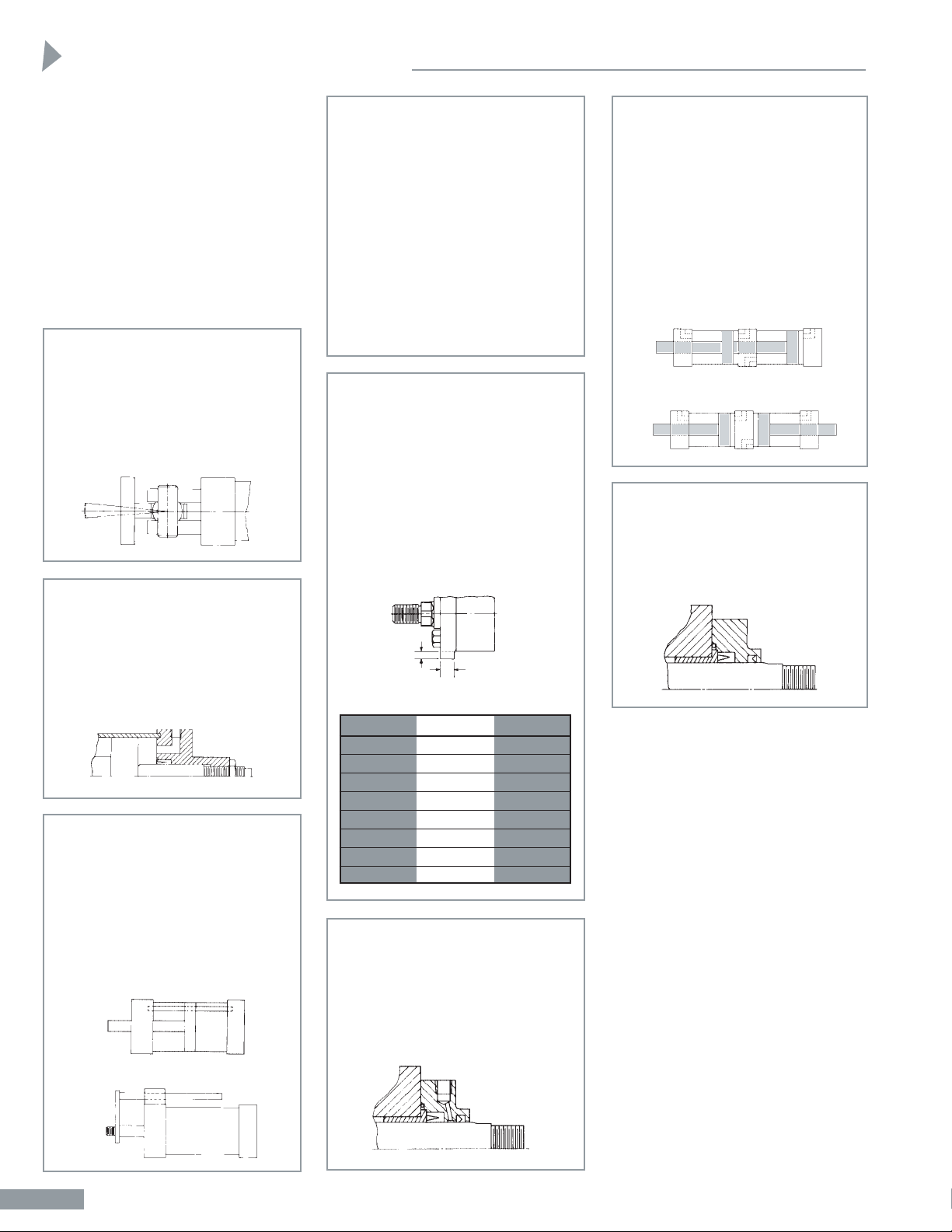
The tandem cylinder (Figure A)
has two pistons connected to a
common rod, resulting in twice
the force output of a single
cylinder. Multi-stage cylinders
(Figure B) offer multiple, positive
strokes by pressurizing one
cylinder, the other, or both.
Contact the factory for other
variations.
Rod Gland Drain Back
When not even a drop of external
leakage can be tolerated, the rod
gland drain back provides a signal
that the rod seal set has worn to the
point of replacement – without the
danger of contamination from
leakage.
External Rod Seal
When a cylinder is to be operated
under water, provision is made to
prevent the water from being drawn
into the cylinder at the time of
valve shift or pressure differential.
Stainless Steel Piston Rods
Many applications, especially those
subjected to water spray, require
the use of stainless steel piston
rods. We stock AISI Type 304 hard
chrome plated, stainless steel and
will furnish that type unless
otherwise specified. Type 304 is
considered a good, corrosion
resistant type of stainless steel, but
the minimum expected yield is
approximately 35,000 psi and that
factor must be considered with
respect to operating pressure,
column loading, etc.
FIGURE B
FIGURE A
Adjustable Stroke
Shown is an integral stroke
adjustment (externally adjusted)
that is accomplished by the use
of a bump rod threaded into the
cylinder cap. Seals are incorporated
to prevent external leakage and a
lock nut is included.
Thrust Key
All side mounted cylinders (SF, FB,
EL and SL mounts) can be supplied
with thrust keys. Thrust keys are
available in bore sizes 1
1
/8" thru 6".
Extending the rod gland retainer,
as shown, provides a key which fits
into a milled slot in the mounting
surface of the machine member.
Combined with the mount this key
assures that cylinder will not shift
in severe service.
Spherical Bearings
Pivot mounting brackets and rod
eyes can be provided with spherical
bearings to compensate for misalignment on both ends of cylinders.
Consider also the use of the Sheffer
Uni-Lign described in separate
Accessories Brochure.
Non-Rotating Piston Rod
Two methods of providing nonrotating piston rods are employed.
The internal rod type
(Figure A)
is generally used since it requires
less space and is neater. The type
shown in Figure B must be used
on small bore cylinders where
internal space is limited.
FIGURE A
FIGURE B
The Sheffer Corporation manufactures
many cylinders with variations to meet
special customer needs. In addition to
those illustrated below, some of the
more popular variations are:
• Cylinders with Boots
• Combination Mount Cylinders
• Cylinders with Built-In Limit
Switch Actuators
• Locking Cylinders
• Precision Stroke Cylinders
• Precision Mount Cylinders
• Electrically Insulated Cylinders
FK
FA ± .0005
Special Variations
BORE FA FK
11/8 .3120
3
/16
11/2 .3120
3
/16
2 .5620
5
/16
21/2 .5620
5
/16
31/4 .6870
3
/8
4 .8120
7
/16
5 .8120
7
/16
6 .9370
1
/2
Thrust Key Bore Sizes
Page 7
Porting
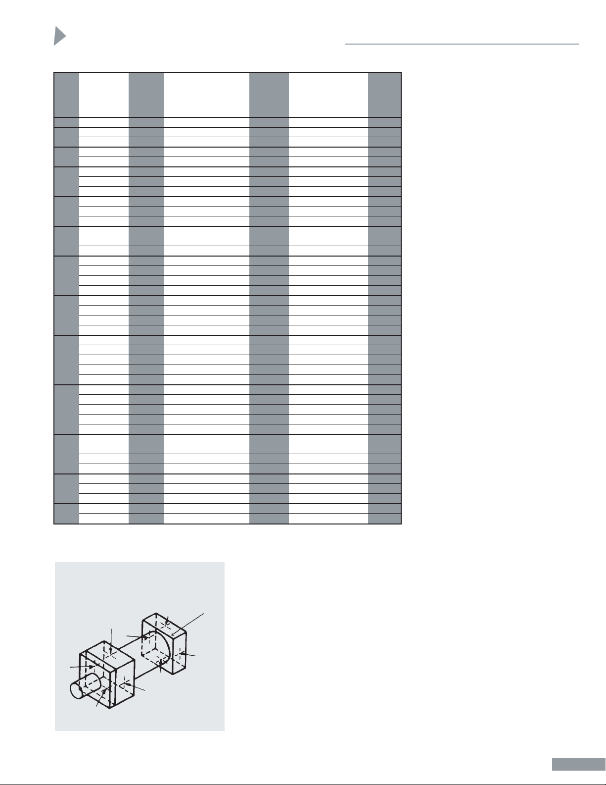
S.A.E. Ports, located in positions 1 and
5 (See Position Diagram for Ports) are
standard and will be furnished unless
otherwise specified. Other types and
sizes of ports are available on request,
at slight additional cost.
Port Positions - Where mounting
clearances permit, the ports can be in
any of four positions in the head and
in the cap at no extra cost. Indicate
both port positions desired by position
number. If no preference is stated, ports
will be furnished in positions 1 and 5.
NOTE: The head and cap can be rotated
in relation to each other as long as
mounting and porting are convenient
for installation.
1 2 3 4 5 6 7
STD. MAX.
S.A.E. S.A.E. MAX.
MM STD. MAX. ST. THRD. S.A.E.
ROD NPT. NPT.PORT THRD. PORT FLG.
BORE DIA. PORT HEAD CAP PORT HEAD CAP PORT
11/8
5
/8 STD.
1
/4
3
/8*
3
/8* -6 -6 -6 —
5
/8 STD.
1
/2
3
/4
3
/4 -10 -10 -10 —
1 2:1
1
/2
3
/4
3
/4 -10 -10 -10 —
1 STD.
1
/2
3
/4*
3
/4* -10 -12* -12* —
13/8 2:1
1
/2
3
/4*
3
/4* -10 -12* -12* —
1 STD.
1
/2
3
/4*
3
/4* -10 -12 -12 3050
13/8
1
/2
3
/4*
3
/4* -10 -12* -12* 3050
13/4 2:1
1
/2
3
/4*
3
/4* -10 -12* -12* 3050
13/8 STD.
3
/4
3
/4 1* -12 -12 -16* 3075
13/4
3
/4
3
/4 1* -12 -12 -16* 3075
2 2:1
3
/4 1* 1* -12 -16* -16* 3075
13/4 STD.
3
/4
3
/4 1* -12 -14 -16* 3075
2
3
/4
3
/4 1* -12 -14 -16* 3075
21/2 2:1
3
/4 1* 1* -12 -14 -16* 3075
2 STD.
3
/4
3
/4 1* -12 -16* -16* 3075
21/2
3
/4 1* 1* -12 -16* -16* 3075
3
3
/4 1* 1* -12 -16* -16* 3075
31/2 2:1
3
/4 1* 1* -12 -16* -16* —
21/2 STD. 1 11/4*1
1
/4* -16 -20* -20* 3125*
3 1 11/4*1
1
/4* -16 -20* -20* 3125*
31/2 1 11/4*1
1
/4* -16 -20* -20* 3125*
4 2:1 1 11/4*1
1
/4* -16 -20* -20* —
3 STD. 11/4 11/2 11/2 -20 -24 -24 3150
31/2 11/4 11/2 11/2 -20 -24 -24 3150
4 11/4 11/2 11/2 -20 -24 -24 3150
41/2 11/4 11/2 11/2 -20 -24 -24 3150
5 2:1 11/4 11/2 11/2 -20 -24 -24 3150
31/2 STD 11/2 22-24 -32* -32* 3200
4 11/2 22-24 -32* -32* 3200
41/2 11/2 22-24 -32* -32* 3200
5 11/2 22-24 -32* -32* 3200
51/2 2:1 11/2 22-24 -32* -32* 3200
41/2 STD. 2 21/2 21/2 -32 -32 -32 3250
5 2 21/2 21/2 -32 -32 -32 3250
51/2 2 21/2 21/2 -32 -32 -32 3250
7 2:1 2 21/2 21/2 -32 -32 -32 3250
51/2 STD. 21/2 33-32 -32 -32 3300
7 21/2 33-32 -32 -32 3300
8 2:1 21/2 33-32 -32 -32 3300
7 STD. 21/2 33-32 -32 -32 3300
10 2:1 21/2 33-32 -32 -32 3300
*Y and P dimensions as shown on mounting dimensions pages must change to
accommodate these port sizes.
Position Diagram for Ports,
Air Bleeds, Cushion Adjusting
Screws and Cushion Checks
1
2
3
4
5
6
7
8
9
1 1/8" THRU 14" BORES
Porting and Air Bleeds
Port Sizes - Standard ports are S.A.E.
and sizes as shown in Column 5 on the
adjacent chart. Unless otherwise
specified, those sizes are what will be
furnished. Smaller than standard
ports can be supplied at no extra
cost. It is recommended that cylinders
be ordered with ports no larger than
needed so that the trouble and expense
of obtaining and installing reducing
fittings can be avoided. At a modest
cost, larger than standard ports, as
shown in COLUMN 6, can be
furnished. While these larger ports
can be put in a standard cylinder, it is
necessary in some cases to slightly alter
the Y and the P dimensions shown
on our mounting dimension pages.
Contact the factory for those
dimensional changes.
S.A.E. Straight Thread Ports - This
type of port offers positive seal with full
thread engagement. It also eliminates
the problem of faulty
pipe threads since sealing takes
place independently of the thread. No
messy pipe dope to bother with or to
contaminate the hydraulic system. No
wedging, distortion, or breakage due
to over-tightening. Alignment and full
sealing are both assured since the
fittings can be tightened after lining up.
Straight thread fittings may be reused,
indefinitely. COLUMN 6 shows the
maximum size of S.A.E. port that can be
furnished in a standard cylinder. Larger
sizes accommodated with special heads
and caps.
S.A.E. Flanged Ports - At a slight
additional cost, flanged ports can be
provided. COLUMN 7 shows the
maximum standard S.A.E. flange sizes
available.
Air Bleeds
An air bleed may be ordered at either
or both ends of the cylinder as an
option. To provide for maximum
bleeding of air from the cylinder,
Sheffer places its air bleeds in the tube
to bleed air from the tube/head or
tube/cap juncture. The air is bled from
the cylinder by backing out the straight
thread metallic seal plug to allow air to
pass by the threads. When air bubbles
stop and oil starts to flow, retighten
plug. It is recommended that bleeding
be done with pressure on the opposite
end of the cylinder so that the bleed
plug is not subjected to pump pressure
when being backed out. Air bleeds
should always be positioned at the
highest point of the cylinder tube.
Please specify positions of air bleeds by
position number from the chart.
NOTE: Since Sheffer puts air bleeds
in the cylinder tube, position can be
changed by loosening the tie rods and
rotating the tube. Photos and Line
Drawings show ports in positions 1
and 5.
11/2
2
2
1
/2
31/4
4
5
6
7
8
10
12
14
Porting Dimensions
HH- 6
Page 8
UF
E
E
TF
R
FB
BOLT
SIZE
FB
BOLT
SIZE
G
WF
Y
J
K
WG
VB
MM
ROD
DIA.
EE
P + STROKE
ZB + STROKE
FA
RD - .001
- .003
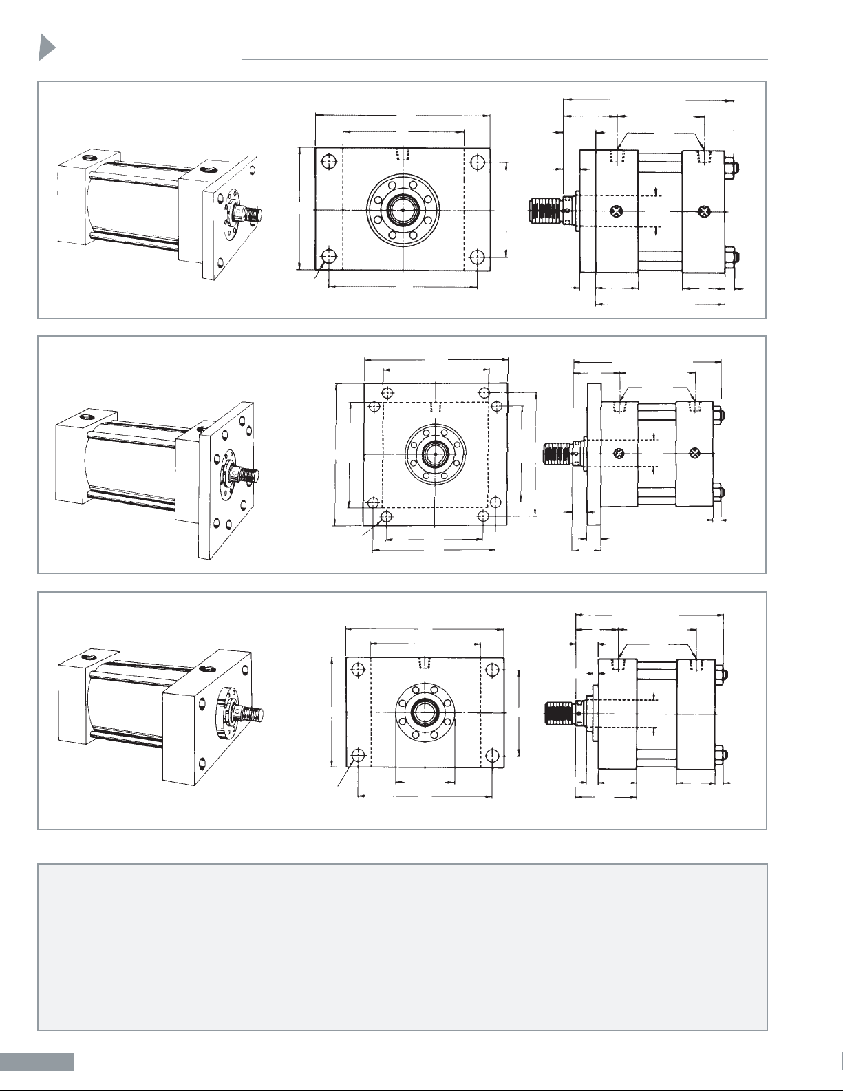
FRONT FLANGE MOUNT
STYLE FF (MF1)*
FRONT FLANGE MOUNT
EXTRA SIZE
STYLE FFX (MF5)*
FRONT HEAD FLANGE MOUNT
STYLE FHF (ME5)*
*ANSI/B93.1-1964 Mounting Style
Designation.
UF
E
E
FB
BOLT
SIZE
TF
R
LB + STROKE
J
G
W
WF
ZB + STROKE
Y
P + STROKE
EE
FF
K
MM
ROD
DIA.
IIMMPPOORRTTAANNTT NNOOTTIICCEE
There is a construction variance in the 11/8", 11/2", 2"
bores, the 21/2" bore with a 13/8" or a 13/4" rod, and in the
31/4" bore with a 2" diameter rod. On the Front Flange
(FF) and Front Flange Extra (FFX) Mounts, in these
sizes, the round retainer shown above is not used. The
tie rods thread into the flange, and the flange serves as
the rod gland retainer. Hence, in these sizes, the gland
cannot be removed without loosening the tie rods. The
basic cylinder dimensions shown above do not change.
On the Front Head Flange Mount (FHF), in the 1
1
/8",
11/2", the 21/2" bore with a 13/4" rod, and the 31/4" bore
with a 2" rod, the retainer is the same rectangular size
as the head. Tie rods thread into the retainer and the
retainer holds in the packing gland. Hence, in these sizes
the gland cannot be removed without loosening the tie
rods. Dimensions for these sizes of the FHF mount
cylinders can be obtained from the Front Flange Mount
(FF) charting. Mounting bolts will clear through both the
flange (FF dimension) and the head (G dimension).
UF
UF E
E
R
R
ZB + STROKE
P + STROKE
EE
MM
ROD
DIA.
Y
W
W
F
FF
K
TF
TF
For assistance in establishing your mounting requirements, also see the s eparate Accessories Brochure.
1000 PSI Rated
FRONT FLANGE MOUNTINGS
Mountings
1
HH-7
Page 9
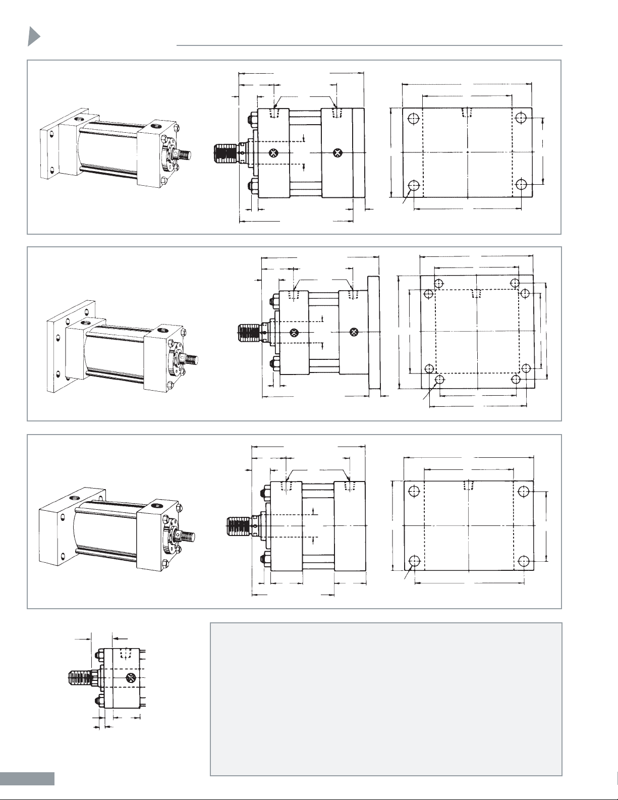
Good – Front Flange Mount
While this style of mount is a widely
used one, its use should be restricted
to pressures under 1000 psi, short
strokes (under 36") and standard rod
diameters. Note that the Front Head
Flange mount has the same mounting
hole pattern.
Better – Front Flange
Extra Mount
Satisfactory for maximum operating
pressure and long strokes if properly
applied. See separate Accessories
Brochure for detailed mounting data
and separate Engineering Brochure for
long stroke information.
Best – Front Head Flange
Mount
Highly recommended. This is the best
style of flange mounting. With this
style, the cylinder can be mounted on
the back face of the Head Flange if
desired. This mounting style is used
extensively on high tonnage presses
and other heavy duty applications. To
dimensionally interchange with the FF
mount, see separate Accessories Brochure
for Front Head Flange Spacer Bars.
We highly recommend that consideration be given to the use of a Style 6 rod
end (see pages HH-21 and HH-22)
and S.A.F.E. Coupling (see separate
Accessories Brochure) to achieve good
radial alignment.
Selection of piston rod diameter can be
determined by consulting the separate
Engineering Brochure.
CAUTION
See separate Accessories Brochure
for information concerning the
application of Flange Mount Cylinders.
MM
ROD
BORE DIA. FA RD VB W WF WG Y ZB*
11/85/8 STD. — — —
5
/8 11/8 21/4 123/32 45/8*
5
/8 STD. — — —
5
/8 1 23/4 2 515/16*
1 2:1 — — — 1 13/8 31/8 23/8 65/16*
1 STD.
11
/32 2.375
7
/8
3
/4 13/8 31/8 23/8 67/16*
13/8 2:119/32 2.875 1 1 15/8 33/8 25/8 611/16*
1 STD.
11
/32 2.375
7
/8
3
/4 13/8 31/8 23/8 69/16*
13/8
19
/32 2.875 1 1 15/8 33/8 25/8 613/16*
13/4 2:1 — — — 11/4 17/8 35/8 27/8 71/16*
13/8 STD.19/32 2.875 1
7
/8 15/8 35/8 23/4 711/16*
13/4
19
/32 3.250 11/8 11/8 17/8 37/8 3 715/16*
2 2:1 — — — 11/4 2 4 31/8 81/16*
13/4 STD.19/32 3.250 11/8 1 17/8 37/8 3 83/16*
2
19
/32 3.562 11/8 11/8 2 4 31/8 85/16*
21/2 2:119/32 4.000 11/4 13/8 21/4 41/4 33/8 89/16*
2 STD.
19
/32 3.562 11/8 11/8 2 4 31/8 9*
21/2
19
/32 4.000 11/4 13/8 21/4 41/4 33/8 91/4*
3
19
/32 4.750 11/4 13/8 21/4 41/4 33/8 91/4*
31/2 2:123/32 5.187 11/4 13/8 21/4 41/4 33/8 91/4*
21/2 STD.19/32 4.000 11/4 11/4 21/4 45/8 31/2 101/2*
3
19
/32 4.750 11/4 11/4 21/4 45/8 31/2 101/2*
31/2
23
/32 5.187 11/4 11/4 21/4 45/8 31/2 101/2*
4 2:1
23
/32 5.750 11/4 11/4 21/4 45/8 31/2 101/2*
3 STD.
19
/32 4.750 11/4 11/4 21/4 51/8 313/16 1115/16*
31/2
23
/32 5.187 11/4 11/4 21/4 51/8 313/16 1115/16*
4
23
/32 5.750 11/4 11/4 21/4 51/8 313/16 1115/16*
41/2
3
/4 6.250 11/4 11/4 21/4 51/8 313/16 1115/16*
5 2:1
3
/4 6.750 11/4 11/4 21/4 51/8 313/16 1115/16*
31/2 STD.23/32 5.187 11/4 11/4 21/4 51/2 315/16 13*
4
23
/32 5.750 11/4 11/4 21/4 51/2 315/16 13*
41/2
3
/4 6.250 11/4 11/4 21/4 51/2 315/16 13*
5
3
/4 6.750 11/4 11/4 21/4 51/2 315/16 13*
51/2 2:13/4 7.250 11/4 11/4 21/4 51/2 315/16 13*
41/2 STD. 15/8 6.250 115/16 11/4 215/16 613/16 5 163/4*
5 15/8 6.750 23/16 11/2 33/16 71/16 51/4 17*
51/2 15/8 7.250 23/16 11/2 33/16 71/16 51/4 17*
7 2:1 15/8 9.750 23/16 2 311/16 79/16 53/4 171/2*
51/2 STD. 15/8 7.250 23/16 11/4 33/16 81/16 53/4 195/8*
7 15/8 9.75 23/16 17/8 313/16 811/16 63/8 201/4*
8 2:1 17/8 10.875 27/16 27/16 43/8 91/4 615/16 2013/16*
7 STD. 23/8 9.75 213/16 17/8 45/16 911/16 77/16 2315/32*
10 2:1 23/8 13.73 215/16 21/2 415/16 105/16 81/16 243/32*
*Be sure to add stroke to this dimension.
EE EE
BORE E NPT† SAE FB** FF G J K LB* P* R TF UF
11/8 13/4
1
/4 -6
1
/4
1
/2 11/8 1
1
/4 31/4* 23/16* 1.19 23/8 3
11/2 21/2
1
/2 -10
3
/8
3
/8 13/4 11/2
5
/16 45/8* 27/8* 1.63 37/16 41/4
2 3
1
/2 -10
1
/2
5
/8 13/4 11/2
7
/16 45/8* 27/8* 2.05 41/8 51/8
21/2 31/2
1
/2 -10
1
/2
5
/8 13/4 11/2
7
/16 43/4* 3* 2.55 45/8 55/8
31/4 41/2
3
/4 -12
5
/8
3
/4 2 13/4
9
/16 51/2* 31/2* 3.25 57/8 71/8
4 5
3
/4 -12
5
/8
7
/8 2 13/4
9
/16 53/4* 33/4* 3.82 63/8 75/8
5 61/2
3
/4 -12
7
/8
7
/8 2 13/4
3
/4 61/4* 41/4* 4.95 83/16 93/4
6 71/2 1 -16 1 1 23/8 23/8
7
/8 73/8* 47/8* 5.73 97/16 111/4
7 81/2 11/4 -20 11/8 1 27/8 27/8 13/16 81/2* 53/8* 6.58 105/8 125/8
8 91/2 11/2 -24 11/4 1 31/4 31/4 11/4 91/2* 61/8* 7.50 1113/16 14
10 125/8 2 -32 13/4 111/16 37/8 37/8 111/16 121/8* 8* 9.62 157/8 19
12 147/8 21/2 -32 2 115/16 47/8 47/8 115/16 141/2* 93/8* 11.45 181/2 22
14 171/4 21/2 -32 21/4 27/16 53/8 53/8 25/32 17* 103/4* 13.34 211/8 251/4
*Be sure to add stroke to this dimension.
**Clearance holes for indicated bolt size.
†Alternate port at no extra charge. SAE port is standard.
14
12
10
8
7
6
5
4
3
1
/4
21/2
2
1
1
/2
1 1/8" THRU 14" BORES
Dimensions
Front Flange Dimensions
Front Flange Dimensions
HH- 8
Page 10
REAR FLANGE MOUNTINGS
Mountings
Y
WF
K
F
UF
FB
BOLT
SIZE
TF
E
E
XF + STROKE
EE
P + STROKE
ZF + STROKE
MM
ROD
DIA.
R
UF
UF
E
E
F
TF
R
R
K
Y
WF
TF
MM
ROD
DIA.
EE
P + STROKE
ZF + STROKE
XF + STROKE
FB
BOLT
SIZE
E
UF
Y
WF
G
J
XK + STROKE
TF
K
WF
FF
K
G
E
R
MM
ROD
DIA.
EE
P + STROKE
FB
BOL
T
SIZE
XF + STROKE
REAR FLANGE MOUNT
STYLE RF (MF2)*
REAR FLANGE MOUNT
EXTRA SIZE
STYLE RFX (MF6)*
REAR HEAD FLANGE MOUNT
STYLE RHF (ME6)*
*ANSI/B93.1-1964 Mounting Style
Designation.
IMPORTANT NOTICE
There is a construction variance
in 11/8", 11/2", 2" bores, the 21/2"
bore with a 13/8" and a 13/4" rod
diameter, and the 31/4" bore with
a 2" diameter rod. The round
retainer shown above is not used
on these sizes. A square retainer,
the same square size as the head is
employed. The retainer is cleared
for the tie rods and held in place
with the tie rod nuts.
In these sizes, the rod gland cannot
be removed without loosening the
tie rods. Dimensions are shown on
the adjacent drawing.
On all other sizes, a round rod
gland retainer is used. It is held in
place by retainer screws–independent of the tie rods, hence, the rod
gland CAN BE removed without
loosening the tie rods.
1000 PSI Rated
1
HH-9
Page 11
Good – Rear Flange Mount
While this style of mount is a widely
used one, its use should be restricted
to pressures under 1000 psi, short
strokes (under 36") and standard rod
diameters. Note that the Rear Head
Flange mount has the same mounting
hole pattern.
Better – Rear Flange
Extra Mount
Satisfactory for maximum operating
pressure and long strokes if properly
applied. See separate Accessories
Brochure for detailed mounting data
and separate Engineering Brochure
for long stroke information.
Best – Rear Head Flange
Mount
Highly recommended. This is the
best style of flange mounting. With
this style, the cylinder can be mounted
on the back face of the flange if
desired. This mounting style is used
extensively on high tonnage presses
and other heavy duty applications.
We highly recommend that
consideration be given to the use
of a Style 6 rod end (see pages HH-21
and HH-22) and S.A.F.E. Coupling
(separate Accessories Brochure) to
achieve good radial alignment.
Selection of piston rod diameter
can be determined by consulting
separate Engineering Brochure.
CAUTION
See separate Accessories Brochure
for information concerning the
application of Flange Mount
Cylinders.
MM
ROD
BORE DIA. WF XF* XK* Y ZF*
11/8
5
/8 STD. 11/8 43/8* 33/8* 123/32 43/4*
5
/8 STD. 1 55/8* 41/8* 2 6*
1 2:1 13/8 6* 41/2* 23/8 63/8*
1 STD. 13/8 6* 41/2* 23/8 65/8*
13/8 2:1 15/8 61/4* 43/4* 25/8 67/8*
1 STD. 13/8 61/8* 45/8* 23/8 63/4*
13/8 15/8 63/8* 47/8* 25/8 7*
13/4 2:1 17/8 65/8* 51/8* 27/8 71/4*
13/8 STD. 15/8 71/8* 53/8* 23/4 77/8*
13/4 17/8 73/8* 55/8* 3 81/8*
2 2:1 2 71/2* 53/4* 31/8 81/4*
13/4 STD. 17/8 75/8* 57/8* 3 81/2*
2 2 73/4* 6* 31/8 85/8*
21/2 2:1 21/4 8* 61/4* 33/8 87/8*
2 STD. 2 81/4* 61/2* 31/8 91/8*
21/2 21/4 81/2* 63/4* 33/8 93/8*
3 21/4 81/2* 63/4* 33/8 93/8*
31/2 2:1 21/4 81/2* 63/4* 33/8 93/8*
21/2 STD. 21/4 95/8* 71/4* 31/2 105/8*
3 21/4 95/8* 71/4* 31/2 105/8*
31/2 21/4 95/8* 71/4* 31/2 105/8*
4 2:1 21/4 95/8* 71/4* 31/2 105/8*
3 STD. 21/4 103/4* 77/8* 313/16 113/4*
31/2 21/4 103/4* 77/8* 313/16 113/4*
4 21/4 103/4* 77/8* 313/16 113/4*
41/2 21/4 103/4* 77/8* 313/16 113/4*
5 2:1 21/4 103/4* 77/8* 313/16 113/4*
31/2 STD. 21/4 113/4* 81/2* 315/16 123/4*
41/2 21/4 113/4* 81/2* 315/16 123/4*
5 21/4 113/4* 81/2* 315/16 123/4*
51/2 2:1 21/4 113/4* 81/2* 315/16 123/4*
41/2 STD. 215/16 151/16* 113/16* 5 163/4*
5 33/16 155/16* 117/16* 51/4 17*
51/2 33/16 155/16* 117/16* 51/4 17*
7 2:1 311/16 1513/16* 1115/16* 53/4 171/2*
51/2 STD. 33/16 1711/16* 1213/16* 53/4 195/8*
7 313/16 185/16* 137/16* 63/8 201/4*
8 2:1 43/8 187/8* 14* 615/16 2013/16*
7 STD. 45/16 215/16* 1515/16* 77/16 233/4*
10 2:1 415/16 2115/16* 169/16* 81/16 243/8*
*Be sure to add stroke to this dimension.
EE EE
BORE E NPT† SAE F FB** FF G J K P* R TF UF
11/8 13/4
1
/4 -6
3
/8
1
/4
1
/2 11/8 1
1
/4 23/16* 1.19 23/8 3
11/2 21/2
1
/2 -10
3
/8
3
/8
3
/8 13/4 11/2
5
/16 27/8* 1.63 37/16 41/4
2 3
1
/2 -10
5
/8
1
/2
5
/8 13/4 11/2
7
/16 27/8* 2.05 41/8 51/8
21/2 31/2
1
/2 -10
5
/8
1
/2
5
/8 13/4 11/2
7
/16 3* 2.55 45/8 55/8
31/4 41/2
3
/4 -12
3
/4
5
/8
3
/4 2 13/4
9
/16 31/2* 3.25 57/8 71/8
4 5
3
/4 -12
7
/8
5
/8 — 2 13/4
9
/16 33/4* 3.82 63/8 75/8
5 61/2
3
/4 -12
7
/8
7
/8 — 2 13/4
3
/4 41/4* 4.95 83/16 93/4
6 71/2 1 -16 1 1 — 23/8 23/8
7
/8 47/8* 5.73 97/16 111/4
7 81/2 11/4 -20 1 11/8 — 27/8 27/8 13/16 53/8* 6.58 105/8 125/8
8 91/2 11/2 -24 1 11/4 — 31/4 31/4 11/4 61/8* 7.50 1113/16 14
10 125/8 2 -32 111/16 13/4 — 37/8 37/8 111/16 8* 9.62 157/8 19
12 147/8 21/2 -32 115/16 2 — 47/8 47/8 115/16 93/8* 11.45 181/2 22
14 171/4 21/2 -32 27/16 21/4 — 53/8 53/8 25/32 103/4* 13.34 211/8 251/4
*Be sure to add stroke to this dimension.
**Clearance holes for indicated bolt size.
†Alternate port at no extra charge. SAE port is standard.
1
1
/2
2
21/2
31/4
4
5
6
7
8
10
12
14
1 1/8" THRU 14" BORES
Dimensions
Rear Flange Dimensions
Rear Flange Dimensions
HH-10
Page 12
LUG MOUNTINGS
Mountings
US
E
TS
SW
SW
ST
E
K
SW
SU
XS
SU
WF
Y
ZB + STROKE
P + STROKE
EE
SS + STROKE
MM
ROD
DIA.
SW
E-.003
2-.008
SB
BOLT
SIZE
US
E
E
TS
SW
SW
ST
SW
SU
XS
WF
Y
SU
SW
K
MM
ROD
DIA.
ZB + STROKE
P + STROKE
EE
SS + STROKE
SB
BOLT
SIZE
E
E
EB
BOLT
SIZE
ET
ET
R
WF
WF
FF
FF
XS
EX
EO
EO
EX
G
WF
K
J
EO
EL
SE + STROKE
EE
P + STROKE
XE+ STROKE
SIDE LUG MOUNT
STYLE SL (MS2)*
CENTER LINE LUG MOUNT
STYLE CL (MS3)*
END LUG MOUNT
STYLE EL (MS7)*
DRAWING A DRAWING B
*ANSI/B93.1-1964 Mounting Style
Designation.
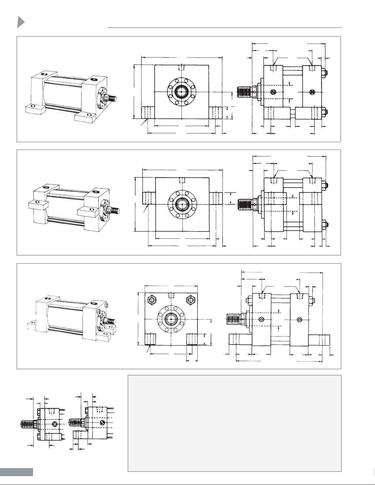
IMPORTANT NOTICE
SL and CL MOUNTS – The round
gland retainer shown above is not used
on the 1
1
/8" bore, 11/2" bore, or the
2
1
/2" bore with a 13/4" rod diameter
and the 3
1
/4" bore with a 2" rod
diameter.
A square retainer, the same square size
as the head is employed on these sizes.
The retainer is held in place with
retainer screws that thread into the
head. The rod gland can be removed
without loosening the tie rods in all
sizes. See adjacent Drawing A.
EL MOUNT – The round gland
retainer shown above is not used on
the 1
1
/8" bore, 11/2" bore, 2" bore, the
2
1
/2" bore with 13/8" and 13/4" rod
diameters, and the 3
1
/4" bore with a 2"
rod diameter. A square retainer, the
same square size as the head, is
employed on these sizes. The lugs
serve as nuts on the bottom two tie
rods, and the top two tie rods use tie
rod nuts. The rod gland cannot be
removed without loosening the tie
rods in these sizes. See adjacent
Drawing B.
MM
ROD
DIA.
E-.003
2-.008
Available 11/8" thru 8" Bore only
1
HH-11
Page 13
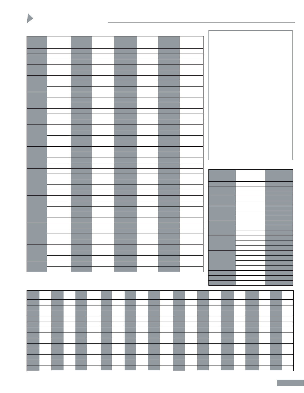
HH-12
CAUTION
When specifying a Side Lug Mount
with ports on the side (port positions
2, 4, 6 or 8), be sure that there will be
enough clearance between the port fitting and the lug to insert a bolt or capscrew into the lug. In small bore sizes,
it may even be necessary to employ a
pipe nipple to easily pipe the port.
When specifying an End Lug Mount,
carefully check the distance between
the rod end and the lug to determine
sufficient clearance for rod end attachment. It may be necessary to add extra
plain rod extension to move the threaded rod end out beyond the lug. When
using a rod eye or rod clevis, we
recommend the extra plain rod extensions in Chart A below be specified.
Consult separate Accessories
Brochure for information concerning
the selection and application of lug
mount cylinders. See separate Engineering Brochure for long stroke cylinder
data. Selection of piston rod diameter
can be determined from information in
separate Engineering Brochure.
MM
ROD
BORE DIA. EX WF XE* XS Y ZB*
11/8
5
/8 STD.
3
/4 11/8 51/8* 13/8 123/32 45/8*
5
/8 STD.
7
/8 1 61/2* 13/8 2 515/16*
1 2:1
7
/8 13/8 67/8* 13/4 23/8 65/16*
1 STD.
15
/16 13/8 615/16* 17/8 23/8 67/16*
13/8 2:1
15
/16 15/8 73/16* 21/8 25/8 611/16*
1 STD. 19/16 13/8 71/16* 21/16 23/8 69/16*
13/8
15
/16 15/8 75/16* 25/16 25/8 613/16*
13/4 2:1
15
/16 17/8 79/16* 29/16 27/8 71/16*
13/8 STD. 17/8 15/8 81/4* 25/16 23/4 711/16*
13/4 17/8 17/8 81/2* 29/16 3 715/16*
2 2:1 11/8 2 85/8* 211/16 31/8 81/16*
13/4 STD. 2 17/8 83/4* 23/4 3 83/16*
2 2 2 87/8* 27/8 31/8 85/16*
21/2 2:1 2 21/4 91/8* 31/8 33/8 89/16*
2 STD. 23/8 2 93/4* 27/8 31/8 9*
21/2 23/8 21/4 10* 31/8 33/8 91/4*
3 23/8 21/4 10* 31/8 33/8 91/4*
31/2 2:1 23/8 21/4 10* 31/8 33/8 91/4*
21/2 STD. 211/16 21/4 115/16* 33/8 31/2 101/2*
3 211/16 21/4 115/16* 33/8 31/2 101/2*
31/2 211/16 21/4 115/16* 33/8 31/2 101/2*
4 2:1 211/16 21/4 115/16* 33/8 31/2 101/2*
3 STD. 213/16 21/4 129/16* 35/8 313/16 1115/16*
31/2 213/16 21/4 129/16* 35/8 313/16 1115/16*
4 213/16 21/4 129/16* 35/8 313/16 1115/16*
41/2 213/16 21/4 129/16* 35/8 313/16 1115/16*
5 2:1 213/16 21/4 129/16* 35/8 313/16 1115/16*
31/2 STD. 3 21/4 133/4* 35/8 315/16 13*
4 3 21/4 133/4* 35/8 315/16 13*
41/2 3 21/4 133/4* 35/8 315/16 13*
5 3 21/4 133/4* 35/8 315/16 13*
51/2 2:1 3 21/4 133/4* 35/8 315/16 13*
41/2 STD. — 215/16 — 49/16 5 163/4*
5 — 33/16 — 413/16 51/4 17*
51/2 — 33/16 — 413/16 51/4 17*
7 2:1 — 311/16 — 55/16 53/4 171/2*
51/2 STD. — 33/16 — 53/16 53/4 195/8*
7 — 313/16 — 513/16 63/8 201/4*
8 2:1 — 43/8 — 63/8 615/16 2013/16*
7 STD. — 45/16 — 69/16 77/16 2315/32*
10 2:1 — 415/16 — 73/16 81/16 243/32*
*Be sure to add stroke to this dimension.
EXTRA
ROD PLAIN
BORE DIAMETER ROD EXT.
11/8
5
/8
1
/2
5
/8
3
/4
1
3
/8
1
13
/16
13/8
9
/16
1
13
/16
13/8
9
/16
13/4
5
/16
13/8 1
13/4
3
/4
2
5
/8
13/4
7
/8
2
3
/4
21/2
1
/2
2 11/4
21/2 1
3 1
31/2 1
6 ALL 17/16
7 ALL 111/16
8 ALL 2
EE EE
BORE E EB** NPT† SAE EL EO ET FF G J K P* R SB** SE* SS* ST SU SW
11/8 13/41/41/4 -63/41/41/21/2 11/8 1
1
/4 23/16* 1.195/16 51/4* 25/8*1/215/163/8
11/2 21/23/81/2 -107/83/813/163/8 13/4 11/25/16 27/8* 1.633/8 63/4* 37/8*1/215/163/8
2 3
1
/21/2 -1015/161/27/85/8 13/4 11/27/16 27/8* 2.051/2 71/8* 35/8*3/4 11/41/2
21/2 31/21/21/2 -1015/161/27/85/8 13/4 11/27/16 3* 2.553/4 71/4* 33/8* 1 19/1611/16
31/4 41/25/83/4 -12 11/85/8 13/163/4 2 13/49/16 31/2* 3.253/4 81/2* 41/8* 1 19/1611/16
4 5
5
/83/4 -12 11/85/8 11/16 — 2 13/49/16 33/4* 3.82 1 87/8* 4* 11/4 2
7
/8
5 61/27/83/4 -12 11/23/4 17/16 — 2 13/43/4 41/4* 4.95 1 101/8* 41/2* 11/4 2
7
/8
6 71/2 1 1 -16 111/167/8 15/8 — 23/8 23/87/8 47/8* 5.73 11/4 113/4* 51/8* 11/2 21/2 11/8
7 81/2 11/8 11/4 -20 113/16 1 13/4 — 27/8 27/8 13/16 53/8* 6.58 11/2 131/8* 53/4* 13/4 27/8 13/8
8 91/2 11/4 11/2 -24 2 11/8 17/8 — 31/4 31/4 11/4 61/8* 7.50 11/2 141/2* 63/4* 13/4 27/8 13/8
10 125/8 — 2 -32 — — — — 37/8 37/8 111/16 8* — 11/2 — 87/8* 21/4 31/2 15/8
12 147/8 — 21/2 -32 — — — — 47/8 47/8 115/16 93/8* — 11/2 — 101/2* 3 41/4 2
14 171/4 — 21/2 -32 — — — — 53/8 53/8 25/32 103/4* — 21/4 — 121/2* 31/2 43/4 21/4
*Be sure to add stroke to this dimension.
**Clearance holes for indicated bolt size.
†Alternate port at no extra charge. SAE port is standard.
TS US
21/2 31/4
31/4 4
4 5
47/8 61/4
57/8 71/4
63/4 81/2
81/4 10
93/4 12
111/4 14
121/4 15
157/8 191/8
187/8 227/8
213/4 261/4
14
1
1
/2
2
2
1
/2
31/4
4
5
6
7
8
10
12
11/2
2
2
1
/2
31/4
4
5
1 1/8" THRU 14" BORES
Dimensions
Lug Mount Cylinder Dimensions
Rod Extensions - Chart A
Lug Mount Cylinder Dimensions
Page 14
TRUNNION MOUNTINGS
Mountings
IMPORTANT NOTICE
TF and TR MOUNTS-The round gland
retainer shown above is not used on
the 1
1
/8" bore, 11/2" bore, or the 21/2"
bore with a 1
3
/4" rod diameter and the
3
1
/4" bore with a 2" rod diameter.
A square gland retainer, the same
square size as the head is employed on
these sizes. The square retainer is held
in place by retainer screws that thread
into the head. The rod gland can be
removed without loosening the tie
rods in all bore sizes. See adjacent
drawing for construction details.
T MOUNT-The round gland retainer
shown above is not used on the 1
1
/8"
bore, 1
1
/2" bore, 2" bore, the 21/2" bore
with a 1
3
/8" or 13/4" rod diameter, or
the 3
1
/4" bore with a 2" rod diameter.
A square gland retainer, the same
square size as the head is employed on
these sizes. The square retainer is held
in place with tie rod nuts and the rod
gland cannot be removed without
loosening the tie rods.
See adjacent drawing for retainer
details.
TRUNNION FRONT MOUNT
STYLE TF (MT1)*
TRUNNION REAR MOUNT
STYLE TR (MT2)*
TRUNNION MOUNT
STYLE T (MT4)*
UT
E
TL
E
XG
K
WF
Y
ZB + STROKE
P + STROKE
EE
MM
ROD
DIA.
TD
+.000
-.001
TD
+.000
-.001
1
/8 R
MAX.
UT
E
ETL
G
WF
Y
K
J
MM
ROD
DIA.
MM
ROD
DIA.
ZB + STROKE
P + STROKE
EE
XJ + STROKE
E
TB
TM
TL
UM
WF
K
TT
Y
K
XI MAX. + STROKE
XI MIN.
EE
P + STROKE
ZB + STROKE
WF
W
G
K
XG
FF
*ANSI/B93.1-1964 Mounting Style
Designation.
(Intermediate - Between Heads)
Position NOT adjustable.
1
/8 R
MAX.
1
/8 R
MAX.
TD
+.000
-.001
NOTE: XI Dimensions must be supplied
by customer on all correspondence
1
HH-13
Page 15
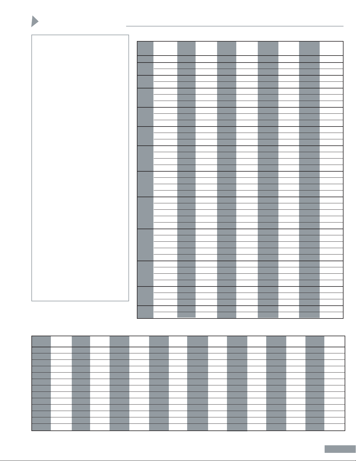
CAUTION
TF mount cylinders in bore sizes
5" through 8" with oversize piston
rods and bore sizes 10", 12" and
14" with all piston rod diameters
should not be used over 2,000 psi.
If your application demands higher
pressure, consult the factory.
Sheffer trunnion pins are an
integral part of the head (TF
Mount), the cap (TR Mount),
or the ring on the intermediate
trunnion mount (T). Even though
machining the pins as an integral
part is the strongest, and most
fatigue-resistant method, some
attention should be given to proper
mounting of trunnion cylinders.
Pillow blocks of ample size and
rigidity should be provided and
should be mounted as close to the
head or cap as possible. Bearing
should be provided for the full
length of the trunnion pin. Pins are
designed for shear loads only, not
bending loads. Lubrication should
be provided to the pins.
All trunnion cylinders need
provision on both ends for pivoting
in one direction. Alignment in the
other direction is essential in order
to avoid excessive side loading.
Where two-direction pivoting is
necessary, contact our distributor
for specific recommendations.
Selection of piston rod diameter
can be determined by consulting
separate Engineering Brochure.
See Engineering Brochure for
information concerning the
application of long stroke cylinders.
See separate Accessories
Brochure for additional data on
cylinder mounting.
MM
ROD XI XI
BORE DIA. W WF MIN. MAX.* XG XJ* Y ZB*
11/85/8 STD.
5
/8 11/8 23/4 27/8* 123/32 329/32* 123/32 45/8*
5
/8 STD.
5
/8 1 33/8 31/2* 17/8 47/8* 2 515/16*
1 2:1 1 13/8 33/4 37/8* 21/4 51/4* 23/8 65/16*
1 STD.
3
/4 13/8 37/8 33/4* 21/4 51/4* 23/8 67/16*
13/8 2:1 1 15/8 41/8 4* 21/2 51/2* 25/8 611/16*
1 STD.
3
/4 13/8 37/8 37/8* 21/4 53/8* 23/8 69/16*
13/8 1 15/8 41/8 41/8* 21/2 55/8* 25/8 613/16*
13/4 2:1 11/4 17/8 43/8 43/8* 23/4 57/8* 27/8 71/16*
13/8 — 15/8 45/8 43/8* 25/8 61/4* 23/4 711/16*
13/4 — 17/8 47/8 45/8* 27/8 61/2* 3 715/16*
2 2:1 11/4 2 5 43/4* 3 65/8* 31/8 81/16*
13/4 STD. — 17/8 5 43/4* 27/8 63/4* 3 83/16*
2 — 2 51/8 47/8* 3 67/8* 31/8 85/16*
21/2 2:1 — 21/4 53/8 51/8* 31/4 71/8* 33/8 89/16*
2 STD. — 2 51/8 53/8* 3 73/8* 31/8 9*
21/2 — 21/4 53/8 55/8* 31/4 75/8* 33/8 91/4*
3 — 21/4 53/8 55/8* 31/4 75/8* 33/8 91/4*
31/2 2:1 — 21/4 53/8 55/8* 31/4 75/8* 33/8 91/4*
21/2 STD. — 21/4 61/8 53/4* 33/8 83/8* 31/2 101/2*
3 — 21/4 61/8 53/4* 33/8 83/8* 31/2 101/2*
31/2 — 21/4 61/8 53/4* 33/8 83/8* 31/2 101/2*
4 2:1 — 21/4 61/8 53/4* 33/8 83/8* 31/2 101/2*
3 STD. — 21/4 65/8 63/8* 35/8 93/8* 313/16 1115/16*
31/2 — 21/4 65/8 63/8* 35/8 93/8* 313/16 1115/16*
4 — 21/4 65/8 63/8* 35/8 93/8* 313/16 1115/16*
41/2 — 21/4 65/8 63/8* 35/8 93/8* 313/16 1115/16*
5 2:1 — 21/4 65/8 63/8* 35/8 93/8* 313/16 1115/16*
31/2 STD. — 21/4 71/4 63/4* 33/4 101/4* 315/16 13*
4 — 21/4 71/4 63/4* 33/4 101/4* 315/16 13*
41/2 — 21/4 71/4 63/4* 33/4 101/4* 315/16 13*
5 — 21/4 71/4 63/4* 33/4 101/4* 315/16 13*
51/2 2:1 — 21/4 71/4 63/4* 33/4 101/4* 315/16 13*
41/2 — 215/16 91/16 815/16* 43/4 131/4* 5 163/4*
5 — 33/16 95/16 93/16* 5 131/2* 51/4 17*
51/2 — 33/16 95/16 93/16* 5 131/2* 51/4 17*
7 2:1 — 311/16 913/16 911/16* 51/2 14* 53/4 171/2*
51/2 STD. — 33/16 1013/16 101/16* 53/8 151/2* 53/4 195/8*
7 — 313/16 117/16 1011/16* 6 161/8* 63/8 201/4*
8 2:1 — 43/8 12 111/4* 69/16 1611/16* 615/16 2013/16 *
7 STD. — 45/16 1211/16 1215/16* 627/32 1825/32* 77/16 2315/32*
10 2:1 — 415/16 135/16 139/16* 715/32 1913/32* 81/16 243/32*
*Be sure to add stroke to this dimension.
EE EE
BORE E NPT† SAE FF G J K P* TB TD TL TM TT UM UT
11/8 13/4
1
/4 -6
1
/2 11/8 1
1
/4 23/16* 13/4
3
/4
3
/4 13/4 1 31/4 31/4
11/2 21/2
1
/2 -10
3
/8 13/4 11/2
5
/16 27/8* 3 1 1 3 11/4 5 41/2
2 3
1
/2 -10
5
/8 13/4 11/2
7
/16 27/8* 31/2 13/8 13/8 31/2 11/2 61/4 53/4
21/2 31/2
1
/2 -10
5
/8 13/4 11/2
7
/16 3* 4 13/8 13/8 4 11/2 63/4 61/4
31/4 41/2
3
/4 -12
3
/4 2 13/4
9
/16 31/2* 5 13/4 13/4 5 2 81/2 8
4 5
3
/4 -12 — 2 13/4
9
/16 33/4* 51/2 13/4 13/4 51/2 21/4 9 81/2
5 61/2
3
/4 -12 — 2 13/4
3
/4 41/4* 71/4 13/4 13/4 7 21/4 101/2 10
6 71/2 1 -16 — 23/8 23/8
7
/8 47/8* 83/4 2 2 81/2 3 121/2 111/2
7 81/2 11/4 -20 — 27/8 27/8 13/16 53/8* 10 21/2 21/2 93/4 3 143/4 131/2
8 91/2 11/2 -24 — 31/4 31/4 11/4 61/8* 113/4 3 3 11 31/2 17 151/2
10 125/8 2 -32 — 37/8 37/8 111/16 8* 141/2 31/2 31/2 14 41/2 21 195/8
12 147/8 21/2 -32 — 47/8 47/8 115/16 93/8* 171/4 4 4 161/2 51/2 241/2 227/8
14 171/4 21/2 -32 — 53/8 53/8 25/32 103/4* 201/2 5 5 195/8 6 295/8 271/4
*Be sure to add stroke to this dimension.
†Alternate port at no extra charge. SAE port is standard.
1
1
/2
2
21/2
31/4
4
5
6
7
8
10
12
14
1 1/8" THRU 14" BORES
Dimensions
Trunnion Dimensions
Trunnion Dimensions
HH-14
Page 16
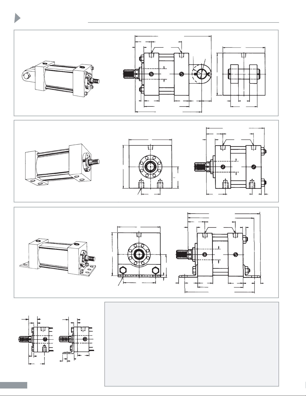
CLEVIS, SIDE FLUSH AND FOOT BRACKET MOUNTINGS
Mountings
IMPORTANT NOTICE
C MOUNT - The round gland retainer
shown above is not used on the 11/8",
11/2", 2" bores, the 21/2" bore with a 13/8"
or 13/4" rod diameter, or the 31/4" bore
with a 2" diameter rod. A square retainer,
the same size as the head, is employed on
these sizes. The square retainer is held in
place with tie rod nuts and the rod gland
cannot be removed without loosening the
tie rods. The retainer thickness is shown
on adjacent Drawing A.
SF MOUNT - The round gland retainer is
not used on the 11/8" bore, 11/2" bore, or
the 21/2" bore with a 13/4" rod diameter
and the 31/4" bore with a 2" rod diameter.
As in the C mount, a square retainer is
employed but it is held in place with
retainer screws that thread into the head
and the rod gland can be removed without loosening the tie rods. See adjacent
Drawing A.
FB MOUNT - The square retainer is used
on 1
1
/8" bore, 11/2" bore, 2" bore, 21/2"
bore with 13/8" and 13/4" rod diameters,
and 31/4" bore with a 2" rod diameter.
The retainer is held in place with retainer
screws that thread into the head. The rod
gland can be removed without loosening
the tie rods, but the front bracket must
also be removed. See adjacent Drawing B.
E
E
E
E
-.003
2-.008
CW
CD
LR
CB
E
E
K
K
Y
Y
WF
WF
XT
GJ
L
MR
CL
NT
TN
LB + STROKE
XC + STROKE
SN + STROKE
MM
ROD
DIA.
MM
ROD
DIA.
EE
EE
P + STROKE
P + STROKE
ZC + STROKE
ZB + STROKE
AVAILABLE 1
1
/8" THRU 8" BORE ONLY
PIVOT MOUNT IS AVAILABLE
PIVOT WIDTH IS SAME AS CB
E
E
1000 PSI Rated
WF
WF
AL
G
FF
FF
K
AO
XT
K
AJ
AT
AO
AO
AL
AL
J
MM
ROD
DIA.
AH
G
Y
WF
EE
P + STROKE
ZA + STROKE
AVAILABLE 1
1
/8" THRU 8" BORE ONLY
XA + STROKE
LB + STROKE
SA + STROKE
AB BOLT SIZE (6 HOLES)
4 HOLES ON
1
/8" BORE
CLEVIS MOUNT
STYLE C (MP1)*
SIDE FLUSH MOUNT
STYLE SF (MS4)*
FOOT BRACKET MOUNT
STYLE FB (MS1)*
DRAWING A DRAWING B
*ANSI/B93.1-1964 Mounting Style
Designation.
1
HH-15
Page 17
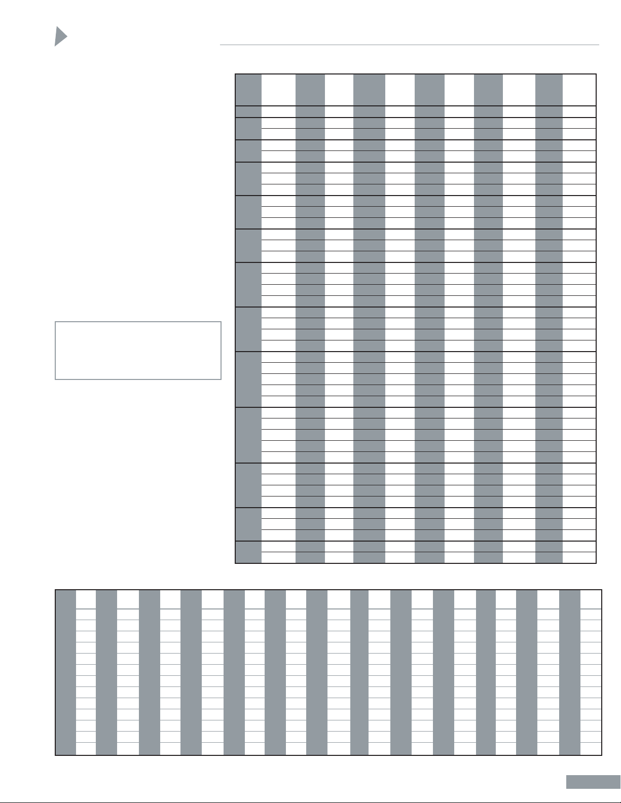
SIDE
MM FLUSH
ROD THREAD
BORE DIA. SA
*
WF XA XC
*
XT Y ZA
*
ZB
*
ZC*DEPTH
11/85/8 STD. 53/4*11/8 53/8 55/16*125/32 123/32 53/4*45/8*511/16
* 3
/8
5
/8 STD. 7
*
1 65/8 63/8
*
2 2 7*515/16*67/8
* 7
/16
1 2:1 7
*
13/8 7 63/4*23/8 23/8 73/8*65/16* 71/4
* 7
/16
1 STD. 73/4*13/8 71/4 71/4*23/8 23/8 73/4*67/16* 8
* 7
/16
13/8 2:1 73/4*15/8 71/2 71/2*25/8 25/8 8*611/16* 81/4
* 7
/16
1 STD. 71/8*13/8 75/16 73/8*23/8 23/8 77/8*69/16* 81/8
* 3
/4
13/8 73/4*15/8 79/16 75/8*25/8 25/8 81/8*613/16* 83/8
* 3
/4
13/4 2:1 73/4*17/8 713/16 77/8*27/8 27/8 83/8*71/16* 85/8*N.A.
13/8 STD. 91/8*15/8 815/16 85/8*23/4 23/4 95/8*711/16* 95/8
*
1
13/4 91/8*17/8 93/16 87/8
*
3 3 97/8*715/16* 97/8
* 7
/8
2 2:1 97/8
*
2 95/16 9
*
31/8 31/8 10*81/16* 10
* 3
/4
13/4 STD. 10*17/8 93/4 93/4
*
3 3 105/8*83/16* 111/8*11/8
2 10
*
2 97/8 97/8*31/8 31/8 103/4*85/16* 111/4
*
1
21/2 2:1 10
*
21/4 101/8 101/8*33/8 33/8 11*89/16* 111/2*N.A.
2 STD. 101/2*2 103/8 101/2*31/8 31/8 111/4*9* 121/4*13/8
21/2 101/2*21/4 105/8 103/4*33/8 33/8 111/2*91/4* 121/2*13/8
3 101/2*21/4 105/8 103/4*33/8 33/8 111/2*91/4*121/2*11/4
31/2 2:1 101/2*21/4 105/8 103/4*33/8 33/8 111/2*91/4*121/2
*
1
21/2 STD. 121/4*21/4 121/16 121/8*31/2 31/2 131/8*101/2*141/8*13/4
3 121/4*21/4 121/16 121/8*31/2 31/2 131/8*101/2*141/8*13/4
31/2 121/4*21/4 121/16 121/8*31/2 31/2 131/8*101/2*141/8*11/2
4 2:1 121/4*21/4 121/16 121/8*31/2 31/2 131/8*101/2*141/8*11/8
3 STD. 147/8*21/4 1315/16 133/4*313/16 313/16 151/4*1115/16*161/4
*
2
31/2 147/8*21/4 1315/16 133/4*313/16 313/16 151/4*1115/16*161/4
*
2
4 147/8*21/4 1315/16 133/4*313/16 313/16 151/4*1115/16*161/4*15/8
41/2 147/8*21/4 1315/16 133/4*313/16 313/16 151/4*1115/16*161/4*11/4
5 2:1 147/8*21/4 1315/16 133/4*313/16 313/16 161/4*1115/16*161/4*N.A.
31/2 STD. 157/8*21/4 1415/16 15*315/16 315/16 161/4*13*173/4*21/4
4 157/8*21/4 1415/16 15*315/16 315/16 161/4*13*173/4*13/4
41/2 157/8*21/4 1415/16 15*315/16 315/16 161/4*13*173/4*13/4
5 157/8*21/4 1415/16 15*315/16 315/16 161/4*13*173/4*15/8
51/2 2:1 157/8*21/4 1415/16 15*315/16 315/16 161/4*13*173/4*11/2
41/2 STD. — 215/16 — 191/16*— 5 — — 229/16*—
5 — 33/16 — 195/16*— 51/4 — — 2213/16*—
51/2 — 33/16 — 195/16*— 51/4 — — 2213/16*—
7 2:1 — 311/16 — 1913/16*— 53/4 — — 235/16*—
51/2 STD. — 33/16 — 223/16*— 53/4 — — 263/16*—
7 — 313/16 — 2213/16*— 63/8 — — 2613/16*—
8 2:1 — 43/8 — 233/8*— 615/16 — — 273/8*—
7STD. — 45/16 — 2713/16*— 77/16 — — 3213/16*—
10 2:1 — 415/16 — 287/16*— 81/16 — — 337/16*—
*
Be sure to add stroke to this dimension.
EE EE
BORE AB** AH AJ AL AO AT CB CD CL CW E NPT† SAE FF G J K L LB
11/85/16 11/16 11/8 13/81/85/83/8 11/45/16 13/41/4 -61/2 11/8 11/415/16 31/4
11/23/8 13/8 13/4 13/81/83/41/2 13/41/2 21/21/2 -103/8 13/4 11/25/163/4 45/8
21/2 111/16 2 11/41/21/8 11/43/4 21/25/8 31/2 -105/8 13/4 11/27/16 11/4 45/8
21/25/8 115/16 23/8 13/169/161/8 11/43/4 21/25/8 31/21/2 -105/8 13/4 11/27/16 11/4 43/4
31/43/4 29/16 31/8 113/1611/161/4 11/2 1 33/4 41/23/4 -123/4 2 13/49/16 11/2 51/2
4 1 213/16 31/4 21/87/81/4 2 13/8 4 1 53/4 -12 — 2 13/49/16 21/8 53/4
5 1 311/16 43/4 21/87/85/16 21/2 13/4 5 11/4 61/23/4 -12 — 2 13/43/4 21/4 61/4
6 11/4 41/4 53/8 27/16 11/163/8 21/2 2 5 11/4 71/2 1 -16 — 23/8 23/87/8 21/2 73/8
7 11/2 415/16 57/8 33/16 15/161/2 3 21/2 6 11/2 81/2 11/4 -20 — 27/8 27/8 13/16 3 81/2
8 11/2 51/2 67/8 33/16 15/161/2 3 3 6 11/2 91/2 11/2 -24 — 31/4 31/4 11/4 31/4 91/2
10 — — — — — — 4 31/2 8 2 125/8 2 -32 — 37/8 37/8 111/16 4 121/8
12 — — ———— 41/2 4 9 21/4 147/8 21/2 -32 — 47/8 47/8 115/16 41/2 141/2
14 — — ———— 6 5 12 3 171/4 21/2 -32 — 53/8 53/8 25/32 61/2 17
*
Be sure to add stroke to this dimension.
**Clearance holes for indicated bolt size.
†Alternate port at no extra charge. SAE port is standard.
LR MR NT P*SN*TN
9
/163/85/16-18 23/16*21/16*—
1
/21/23/8-16 27/8*27/8
* 3
/4
3
/43/41/2-13 27/8*27/8
* 15
/16
3
/43/45/8-11 3*3*15/16
1 13/4-10 31/2*31/2*11/2
13/8 13/8 1-8 33/4*33/4*21/16
13/4 13/4 1-8 41/4*41/4*215/16
2 2 11/4-7 47/8*51/8*35/16
21/2 21/2 11/2-6 53/8*57/8*33/4
23/4 23/4 11/2-6 61/8*65/8*41/4
31/2 31/2 — 8*— —
4 4 — 93/8*— —
5 5 — 103/4*— —
11/2
2
2
1
/2
31/4
4
5
6
7
8
10
12
14
1 1/8" THRU 14" BORES
Dimensions
Clevis, Side Flush and Foot Bracket Dimensions
Side Flush Mount – Notes
• Available 1
1
/2" through 8" bore sizes
only.
• Some bore and rod combinations are
not available in this mount.
• NA means not available.
• The 11/8" bore has only one tapped
hole in the head and in the cap.
Foot Bracket Mount – Notes
• Available 11/2" through 8" bore
sizes only.
• This style of mount is not recom-
mended for pressures in excess
of 1000 psi or strokes over 36 inches.
Consider the use of an End Lug
mount or a Side Lug mount shown
on Page HH-11.
Selection of Piston Rod Diameter can
be determined by consulting separate
Engineering Brochure.
See Engineering Brochure for long
stroke cylinder data.
CAUTION
Refer to separate Accessories
Brochure for information concerning the mounting of cylinders.
Clevis, Side Flush and Foot Bracket Dimensions
HH-16
Page 18
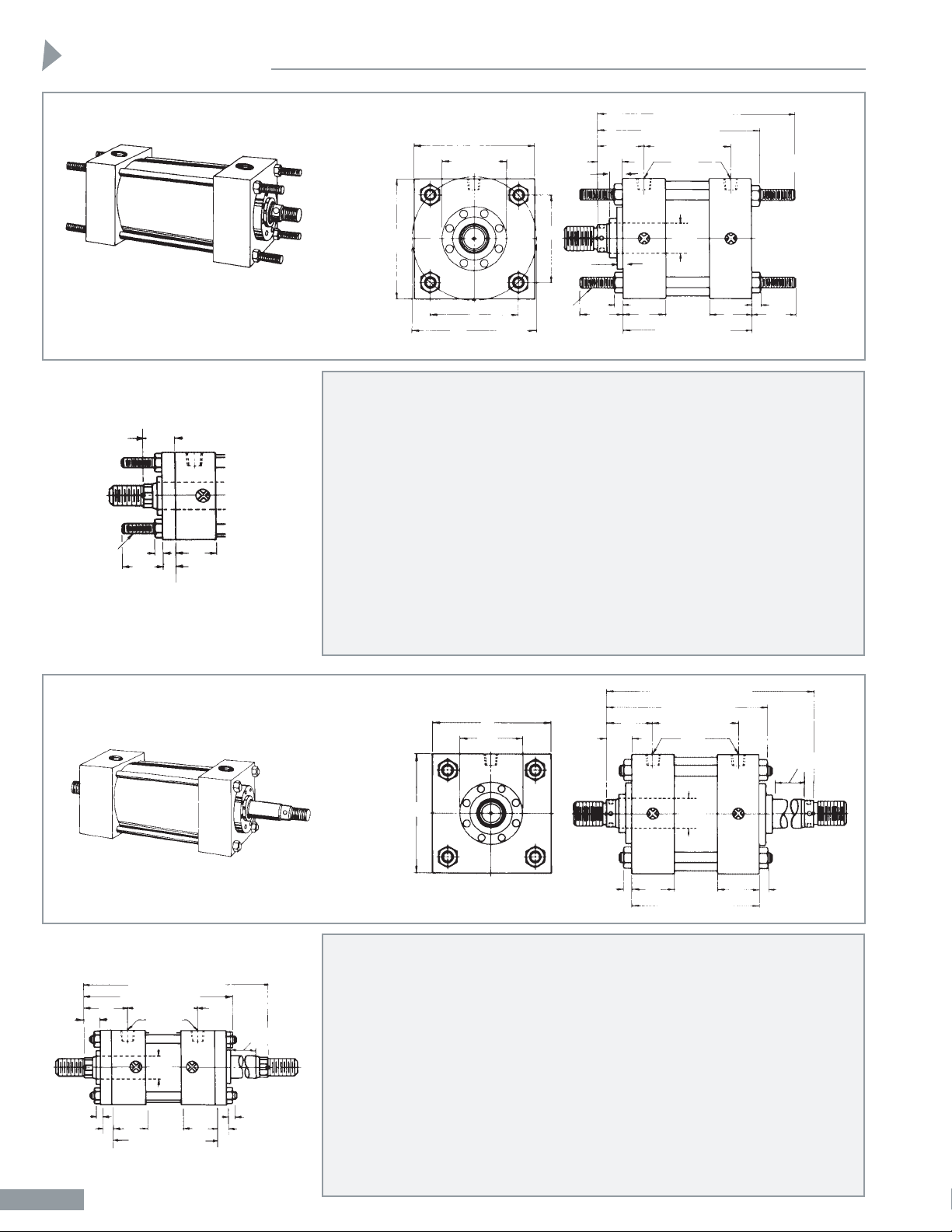
IMPORTANT NOTICE
There is a construction variance in
the 11/8" bore, 11/2" bore, 2" bore,
the 21/2" bore with a 13/8" and 13/4"
rod diameter, and the 31/4" bore
with a 2" rod diameter. The round
gland retainers shown above are not
used in these sizes. A square
retainer, the same square size as the
head, is employed on each end. The
retainers are held in place by the tie
rod nuts and therefore cannot be
removed without loosening the tie
rods.
See adjacent drawing for dimension
details.
For dimensions on specific
mounting styles, consult other
pages in this brochure and separate
Accessories Brochure. Dimensions
shown on the above and adjacent
drawings are for the BASIC
CYLINDER ONLY.
Double rod extension cylinders are
available in every mounting style
except clevis.
IMPORTANT NOTICE
Reference adjacent drawing.
RX MOUNT - The round gland
retainer shown above is not used on
the 11/8" bore, 11/2" bore, or the 21/2"
bore with a 13/4" rod diameter or the
31/4" bore with a 2" rod diameter. A
square retainer, the same square size
as the head, is employed in these
sizes. The retainer is held in place
with retainer screws and the gland
can be removed without loosening
the tie rods.
FX and BX MOUNTS - The square
retainer is used on the 11/8" bore,
11/2" bore, 2" bore, the 21/2" bore
with a 1
3
/8"and 13/4" rod diameter,
and the 31/4" bore with a 2" rod
diameter. The retainer is held in place
by the tie rod nuts, hence, the gland
cannot be removed without loosening
the tie rods.
NX MOUNT - The square retainer is
used on the 11/8" bore, 11/2" bore, and
the 2" bore with a 13/4" diameter rod
and the 31/4" bore with a 2" rod
diameter. The retainer is held in
place with retainer screws that thread
into the head and the rod gland can
be removed without loosening the tie
rods.
ZT + STROKE
ZB + STROKE
P + STROKE
EE
LB + STROKE
Y
VB
RD-.001
-.003
K
G
G
BB
BB
FF
J
BB
DD
FA
WF
WF
R
E
R
AA
B. C. DIA.
E
MM
ROD
DIA.
K
E
RD
E
G
G
G
K
K
K
FF
FF
G
Y
Y
WF
W
STROKE
STROKE
MM
ROD
DIA.
MM
DIA.
EE
EE
P + STROKE
P + STROKE
ZL + STROKE
ZL + STROKE
ZM + (2 x STROKE)
ZM + (2 x STROKE)
LD + STROKE
LD + STROKE
K
TIE RODS EXTENDED
NX - Neither (MXO)*
BX - Both (MX1)*
RX - Rear (MX2)*
FX - Front (MX3)*
*ANSI/B93.1-1964 Mounting Style
Designation.
Available in all except C mounts.
BASIC DOUBLE ROD CYLINDERS
DD
K
TIE ROD AND DOUBLE ROD MOUNTINGS
Mountings
1
HH-17
Page 19
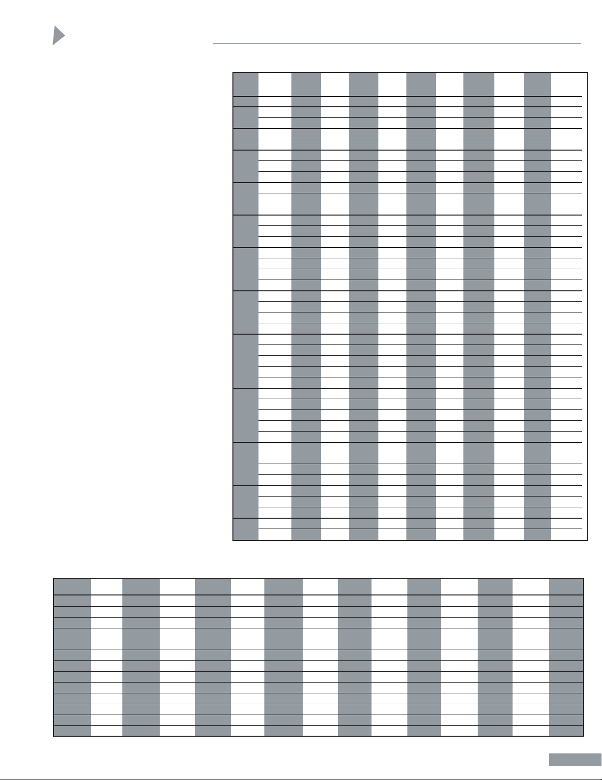
Double Rod End Cylinders
Double Rod End cylinders are
specified for many reasons, some
of which are as follows:
1. A simultaneous push and pull
requirement.
2. Both rod ends are fixed and the
cylinder moves — such as on a
machine slide.
3. One rod does the work and the
other serves to indicate position
or to trip switches.
4. A double rod end cylinder has
rod bearings at each end and
therefore offers more resistance
to deflection and side loading.
When the rod ends of a double
rod end cylinder are not to be the
same, such as a style 2 on one end
and a style 4 on the other, be sure
to so specify and to identify which
end is which in relation to the
mount. For example, on a Front
Head Flange mount double rod
end cylinder, specify style 2 rod
end on flange end of cylinder and
style 4 on opposite end.
Refer to Pages HH-21 and HH-22
for Rod End Information.
MM
ROD
BORE DIA. FA VB RD W WF Y ZB ZL* ZM* ZT*
11/85/8 STD. — — —
5
/8 11/8 123/32 45/8 51/4* 55/8* 53/8*
5
/8 STD. — — —
5
/8 1 2 515/16 69/16* 67/8* 7*
1 2:1 — — — 1 13/8 23/8 65/16 615/16* 75/8* 73/8*
1 STD.11/32
7
/8 2.375
3
/4 13/8 23/8 67/16 75/16* 75/8* 713/16*
13/8 2:119/32 1 2.875 1 15/8 25/8 611/16 79/16* 81/8* 81/16*
1 STD.11/32
7
/8 2.375
3
/4 13/8 23/8 69/16 613/16* 73/4* 715/16*
13/8
19
/32 1 2.875 1 15/8 25/8 613/16 711/16* 81/4* 83/16*
13/4 2:1 — — — 11/4 17/8 27/8 71/16 715/16* 83/4* 87/16*
13/8 STD.19/32 1 2.875 — 15/8 23/4 711/16 715/16* 9* 97/16*
13/4
19
/32 11/8 3.250 — 17/8 3 715/16 83/16* 91/2* 911/16*
2 2:1 — — — 11/4 2 31/8 81/16 91/16* 93/4* 913/16*
13/4 STD.19/32 11/8 3.250 — 17/8 3 83/16 87/16* 93/4* 915/16*
2
19
/32 11/8 3.562 — 2 31/8 85/16 89/16* 10* 101/16*
21/2 2:119/32 11/4 4.000 — 21/4 33/8 89/16 813/16* 101/2* 105/16*
2 STD.19/32 11/8 3.562 — 2 31/8 9 91/4* 101/2* 117/16*
21/2
19
/32 11/4 4.000 — 21/4 33/8 91/4 91/2* 11* 1111/16*
3
19
/32 11/4 4.750 — 21/4 33/8 91/4 91/2* 11* 1111/16*
31/2 2:123/32 11/4 5.187 — 21/4 33/8 91/4 91/2* 11* 1111/16*
21/2 STD.19/32 11/4 4.000 — 21/4 31/2 101/2 101/2* 117/8* 131/4*
3
19
/32 11/4 4.750 — 21/4 31/2 101/2 101/2* 117/8* 131/4*
31/2
23
/32 11/4 5.187 — 21/4 31/2 101/2 101/2* 117/8* 131/4*
4 2:123/32 11/4 5.750 — 21/4 31/2 101/2 101/2* 117/8* 131/4*
3 STD.19/32 11/4 4.750 — 21/4 313/16 1115/16 1115/16* 13* 147/8*
31/2
23
/32 11/4 5.187 — 21/4 313/16 1115/16 1115/16* 13* 147/8*
4
23
/32 11/4 5.750 — 21/4 313/16 1115/16 1115/16* 13* 147/8*
41/2
3
/4 11/4 6.250 — 21/4 313/16 1115/16 1115/16* 13* 147/8*
5 2:13/4 11/4 6.750 — 21/4 313/16 1115/16 1115/16* 13* 147/8*
31/2 STD.23/32 11/4 5.187 — 21/4 315/16 13 13* 14* 161/4*
4
23
/32 11/4 5.750 — 21/4 315/16 13 13* 14* 161/4*
41/2
3
/4 11/4 6.250 — 21/4 315/16 13 13* 14* 161/4*
5
3
/4 11/4 6.750 — 21/4 315/16 13 13* 14* 161/4*
51/2 2:13/4 11/4 7.250 — 21/4 315/16 13 13* 14* 161/4*
41/2 STD. 15/8 115/16 6.250 — 215/16 5 163/4 163/4* 18* 211/16*
5 15/8 23/16 6.750 — 33/16 51/4 17 17* 181/2* 215/16*
51/2 15/8 23/16 7.250 — 33/16 51/4 17 17* 181/2* 215/16*
7 2:1 15/8 23/16 9.75 — 311/16 53/4 171/2 171/2* 191/2* 2113/16*
51/2 STD. 15/8 23/16 7.250 — 33/16 53/4 195/8 195/8* 207/8* 2411/16*
7 15/8 23/16 9.75 — 313/16 63/8 201/4 201/4* 221/8* 255/16*
8 2:1 17/8 27/16 10.875 — 43/8 615/16 2013/16 2013/16* 231/4* 257/8*
7 STD. 23/8 213/16 9.75 — 45/16 77/16 2315/16 2315/16* 255/8* 295/16*
10 2:1 23/8 215/16 13.75 — 415/16 81/16 243/32 243/32* 267/8* 2915/16*
*Add stroke to these dimensions. Add 2X stroke to ZM dimensions.
EE EE
BORE AA BB DD E NPT† SAE FF G J K LB* LD* P* R
11/8 1.68 1
1
/4-28 13/4
1
/4 -6
1
/2 11/8 1
1
/4 31/4
*
33/8*23/16
*
1.19
11/2 2.3 13/8
3
/8-24 21/2
1
/2 -10
3
/8 13/4 11/2
5
/16 45/8
*
47/8
*
27/8
*
1.63
2 2.9 113/161/2-20 3
1
/2 -10
5
/8 13/4 11/2
7
/16 45/8
*
47/8
*
27/8
*
2.05
21/2 3.6 113/161/2-20 31/2
1
/2 -10
5
/8 13/4 11/2
7
/16 43/4
*
5
*
3
*
2.55
31/4 4.6 25/165/8-18 41/2
3
/4 -12
3
/4 2 13/4
9
/16 51/2
*
53/4
*
31/2
*
3.25
4 5.4 25/165/8-18 5
3
/4 -12 — 2 13/4
9
/16 53/4
*
6
*
33/4
*
3.82
5 7.0 33/167/8-14 61/2
3
/4 -12 — 2 13/4
3
/4 61/4
*
61/2
*
41/4
*
4.95
6 8.1 35/8 1-14 71/2 1 -16 — 23/8 23/8
7
/8 73/8
*
73/8
*
47/8
*
5.73
7 9.3 41/8 11/8-12 81/2 11/4 -20 — 27/8 27/8 13/16 81/2
*
81/2
*
53/8
*
6.58
8 10.6 41/2 11/4-12 91/2 11/2 -24 — 31/4 31/4 11/4 91/2
*
91/2
*
61/8
*
7.50
10 13.6 6 13/4-12 125/8 2 -32 — 37/8 37/8 111/16 121/8*121/8
*
8
*
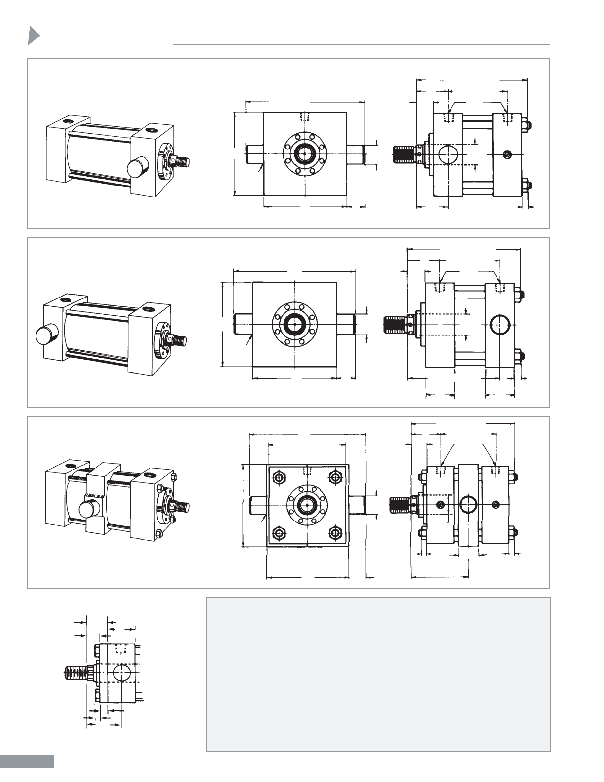
9.62
12 16.2 7 2-12 147/8 21/2 -32 — 47/8 47/8 115/16 141/2*141/2*93/8
*
11.45
14 18.9 8 21/4-12 171/4 21/2 -32 — 53/8 53/8 25/32 17
*
17
*
103/4* 13.34
†Alternate port at no extra charge. SAE port is standard.
*Add stroke to these dimensions.
11/2
2
2
1
/2
31/4
4
5
6
7
8
10
12
14
1 1/8" THRU 14" BORES
Dimensions
Tie Rod and Double Rod Dimensions
Tie Rod and Double Rod Dimensions
HH-18
Page 20
1
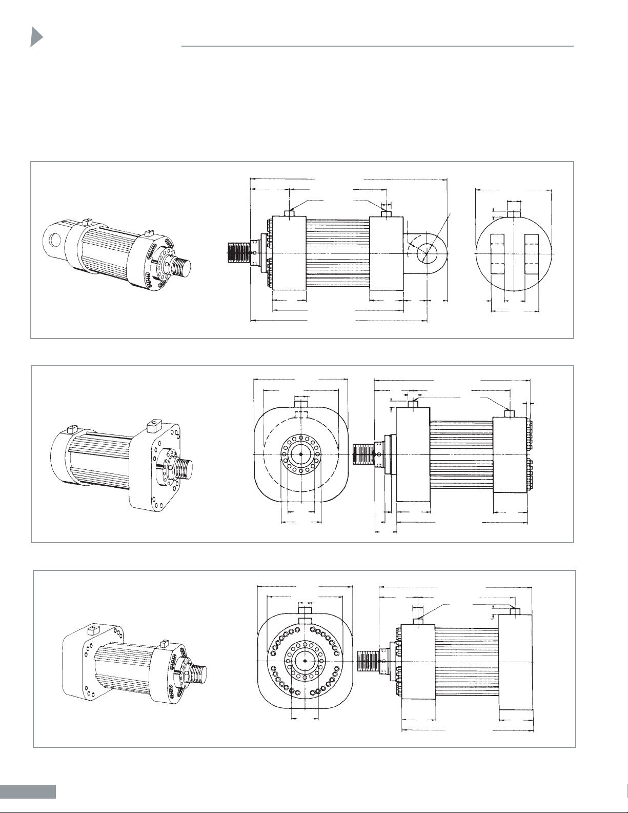
LARGE BORE MOUNTINGS
Mountings
CLEVIS MOUNT
STYLE C
FRONT HEAD MOUNT
STYLE FH
REAR HEAD MOUNT
STYLE RH
ZC + STROKE
ZB+ STROKE
P + STROKE
P + STROKE
LB + STROKE
LB + STROKE
XC + STROKE
E SQ.
EE
EE
PC
LR
CD
EX DIA.
EX DIA.
PB
PB
PC
PA
PA
MM
RD
F
A
VB
WB
G
J
CW
CB
CL
G
Y
Y
K
J
L
MR
ZJ + STROKE
P + STROKE
LB + STROKE
E SQ.
EE
EX DIA.
PB
PC
PA
M
M
G
J
Y
Cylinders of these very large bore sizes,
are frequently custom made to suit
specific customer requirements. Even
though these sizes are not production
run products (expect longer delivery
time than experienced with smaller
bore sizes), basic design criteria and
dimensions have been established by
Sheffer for the three most popular
mounting styles.
We will be happy to quote you on
variations of these mounts or on
mounting styles not shown. To reduce
costs and delivery time, whenever
possible design to the standard mounts
and dimensions shown.
Large Bore Cylinders
HH-19
Page 21
Large Bore Dimensions
BORE 16 18 20 24
CB 61/2 71/2 8 9
CD 6 7 8 9
CL 13 15 16 18
CW 31/4 33/4 4 41/2
E 231/2 271/4 31 361/2
EE 3" 3" 3" 31/2"
MAX. PIPE PIPE PIPE PIPE
EX
DIA. 213/8 241/4 261/2 32
FA 1 1 1 1
G 57/8 63/8 73/8 77/8
J 57/8 63/8 73/8 77/8
K
3
/4
7
/8
7
/8 11/16
L 7 8 9 11
LB 18 20 23 253/4
LR 6 7 8 9
MR 6 7 8 9
P 121/4 131/4 141/4 163/4
PA
MAX. 55/16 55/16 55/16 6
PB
MAX. 23/4 23/4 23/4 31/2
PC
MAX. 41/4 41/4 41/4 5
WB 33/8 33/8 33/8 4
XC 283/8 313/8 353/8 403/4
Y 61/4 63/4 73/4 81/2
ZB 221/8 241/4 271/4 3013/16
ZC 343/8 383/8 433/8 493/4
ZJ 213/8 233/8 263/8 293/4
Maximum Pressure Ratings
3:1
HEAVY MAX. SAFETY
DUTY SHOCK FACTOR
BORE SERVICE SERVICE (YIELD)
SIZE PSI PSI PSI
16 3,000 5,000 2380
18 3,000 5,000 2417
20 3,000 5,000 2447
24 3,000 5,000 2323
Rod End Dimensions
BORE 16 16 16 18 18 20 24
MM
ROD DIA. 8 9 10 9 10 10 12
A 8 9 10 9 10 10 12
C 1 1 1 1 1 1 1
CC 73/4-12 83/4-12 93/4-12 83/4-12 93/4-12 93/4-12 113/4-12
KK 53/4-12 61/2-12 71/4-12 61/2-12 71/4-12 71/4-12 83/4-12
NA
±.002 7.875 8.875 9.875 8.875 9.8775 9.875 11.875
RD
–.001
–.003 10.875 12.500 13.750 12.500 13.750 13.750 16.500
VB 23/8 23/8 23/8 23/8 23/8 23/8 3
Large Bore Rod End
STYLE 2 STANDARD
Style 3
Style 4
RD
RD
RD
RD
A
A
A
C
C
C
VB
VB
VB
KK THREAD
CC THREAD
KK THREAD
1
/2" SPANNER
HOLES
1
/2" SPANNER
HOLES
1
/2"
SPANNER
HOLES
20°
MM
DIA.
MM
DIA.
MM
DIA.
MM
DIA.
NA DIA.
NA DIA.
NA
DIA.
VB
C
1
/16
-0
1
8
2
3
9
/
1
6
B
.
C
.
15/16 DIA.
4 HOLES
PER
CORNER
12
°
1
2
°
2
7
°
1
2
°
15/16 DIA.
5 HOLES
PER
CORNER
18" BORE
1
2
°
1
2
°
12°
2
6
1
/
2
B
.
C
.
20" BORE
1
5
°
15°
1
5
°
2
9
B
.
C
.
15/16 DIA.
6 HOLES PER
CORNER
24" BORE
1
2
°
1
2
°
1
2
°
Details of Placement of
Mounting Holes in Each Corner
IMPORTANT NOTE:
All figures in the chart below are
based on the cylinders as a pressure
vessel. Some styles of mounting will
not withstand the thrust generated at
these pressures. Contact the factory
for specific data.
2
1
°
1
2
°
1
5
°
15°
1
5
°
1
2
°
12°
19/16 DIA.
5 HOLES PER
CORNER
3
4
B
.
C
.
16" THRU 24" BORES
Dimensions
16" BORE
Style 1
1
HH-20
Page 22
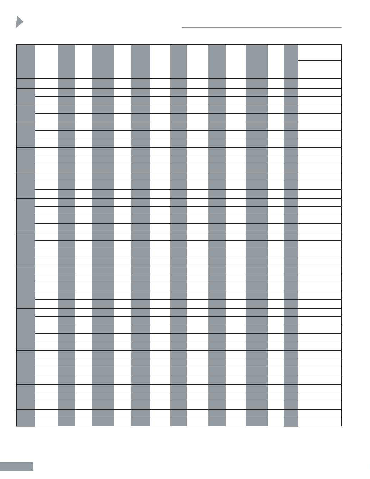
Rod End Dimensions
WRENCH FLATS
OR
SPANNER HOLES
B MALE STYLE
MM DIA. NA THREAD 4
ROD AF -.001 DIA. ROD ROD
BORE DIA. A AC AD AE DIA. -.003 C CC D KK ±.002 V VA* ENDS END
11/85/8 STD.3/4 11/8
5
/8
1
/4
3
/8 11/8
3
/8
1
/2-201/27/16-20 .594
1
/4 — W.F. W.F.
5
/8 STD.3/4 11/8
5
/8
1
/4
3
/8 11/8
3
/8
1
/2-201/27/16-20 .594
1
/4 — W.F. W.F.
1 2:1 11/8 11/2
15
/16
3
/8
11
/16 11/2
1
/2
7
/8-1413/163/4-16 .968
1
/2 — W.F. W.F.
1 STD. 11/8 11/2
15
/16
3
/8
11
/16 11/2
1
/2
7
/8-1413/163/4-16 .968
1
/417/32 W/F. W.F.
13/8 2:1 15/8 13/4 11/16
3
/8
7
/8 2
5
/8 11/4-12 11/8 1-14 1.343
3
/813/32 W.F. W.F.
1 STD. 11/8 11/2
15
/16
3
/8
11
/16 11/2
1
/2
7
/8-1413/163/4-16 .968
1
/417/32 W.F. W.F.
13/8 15/8 13/4 11/16
3
/8
7
/8 2
5
/8 11/4-12 11/8 1-14 1.343
3
/813/32 W.F. W.F.
13/4 2:1 2 2 15/16
1
/2 11/8 23/8
3
/4 11/2-12 11/2 11/4-12 1.703
1
/2 — W.F. W.F.
13/8 STD. 15/8 13/4 11/16
3
/8
7
/8 2
5
/8 11/4-12 11/8 1-14 1.3431/4‡13/32 W.F. W.F.
13/4 2 2 15/16
1
/2 11/8 23/8
3
/4 11/2-12 11/2 11/4-12 1.7033/8‡17/32 W.F. W.F.
2 2:1 21/4 25/8 111/165/8 13/8 25/8
7
/8 13/4-12 15/8 11/2-12 1.953
3
/8 — W.F. W.F.
13/4 STD. 2 2 15/16
1
/2 11/8 23/8
3
/4 11/2-12 11/2 11/4-12 1.7031/4‡17/32 W.F. W.F.
2 21/4 25/8 111/165/8 13/8 25/8
7
/8 13/4-12 15/8 11/2-12 1.9531/4‡17/32 W.F. W.F.
21/2 2:1 3 31/4 115/163/4 13/4 31/8 1 21/4-12 21/16 17/8-12 2.4533/8‡21/32 W.F. W.F.
2 STD. 21/4 25/8 111/165/8 13/8 25/8
7
/8 13/4-12 15/8 11/2-12 1.9531/4‡17/32 W.F. W.F.
21/2 3 31/4 115/163/4 13/4 31/8 1 21/4-12 21/16 17/8-12 2.4533/8‡21/32 W.F. W.F.
3 31/2 35/8 27/16
7
/8 21/4 33/4 1 23/4-12 29/16 21/4-12 2.9373/8‡21/32 S.H. W.F.
31/2 2:1 31/2 43/8 211/16 1 21/2 41/4 1 31/4-12 3 21/2-12 3.4373/8‡17/32 S.H. W.F.
21/2 STD. 3 31/4 115/163/4 13/4 31/8 1 21/4-12 21/16 17/8-12 2.4531/4‡21/32 W.F. W.F.
3 31/2 33/4 27/16
7
/8 21/4 33/4 1 23/4-12 29/16 21/4-12 2.9371/4‡21/32 S.H. W.F.
31/2 31/2 43/8 211/16 1 21/2 41/4 1 31/4-12 3 21/2-12 3.4371/4‡17/32 S.H. W.F.
4 2:1 4 41/2 211/16 1 3 43/4 1 33/4-12 37/16 3-12 3.9371/4‡17/32 S.H. W.F.
3 STD. 31/2 33/4 27/16
7
/8 21/4 33/4 1 23/4-12 29/16 21/4-12 2.9371/4‡21/32 S.H. W.F.
31/2 31/2 43/8 211/16 1 21/2 41/4 1 31/4-12 3 21/2-12 3.4371/4‡17/32 S.H. W.F.
4 4 41/2 211/16 1 3 43/4 1 33/4-12 37/16 3-12 3.9371/4‡17/32 S.H. W.F.
41/2 41/2 51/4 33/16 11/2 31/2 51/4 1 41/4-12 — 31/4-12 4.4211/4‡1/2 S.H. S.H.
5 2:1 5 53/8 33/16 11/2 37/8 53/4 1 43/4-12 — 31/2-12 4.9211/4‡1/2 S.H. S.H.
31/2 STD. 31/2 43/8 211/16 1 21/2 41/4 1 31/4-12 3 21/2-12 3.4371/4‡17/32 S.H. W.F.
4 4 41/2 211/16 1 3 43/4 1 33/4-12 37/16 3-12 3.9371/4‡17/32 S.H. W.F.
41/2 41/2 51/4 33/16 11/2 31/2 51/4 1 41/4-12 — 31/4-12 4.4211/4‡1/2 S.H. S.H.
5 5 53/8 33/16 11/2 37/8 53/4 1 43/4-12 — 31/2-12 4.9211/4‡1/2 S.H. S.H.
51/2 2:1 51/2 61/4 315/16 17/8 43/8 61/4 1 51/4-12 — 4-12 5.4211/4‡1/2 S.H. S.H.
41/2 STD. 41/2 51/4 33/16 11/2 31/2 51/4 1 41/4-12 — 31/4-12 4.4211/4‡5/16 S.H. S.H.
5 5 53/8 33/16 11/2 37/8 53/4 1 43/4-12 — 31/2-12 4.9211/2‡9/16 S.H. S.H.
51/2 51/2 61/4 315/16 17/8 43/8 61/4 1 51/4-12 — 4-12 5.4211/2‡9/16 S.H. S.H.
7 2:1 7 67/8 45/16 17/8 53/4 8 11/2 63/4-12 — 51/4-12 6.9061/2‡9/16 S.H. S.H.
51/2 STD. 51/2 61/4 315/16 17/8 43/8 61/4 1 51/4-12 — 4-12 5.4211/4‡9/16 S.H. S.H.
7 7 7 45/16 17/8 53/4 8 15/8 63/4-12 — 51/4-12 6.9061/4‡9/16 S.H. S.H.
8 2:1 8 53/4 33/16 11/2 63/8 9 115/16 73/4-12 — 53/4-12 7.8751/2‡9/16 S.H. S.H.
7 STD. 7 67/8 45/16 17/8 53/4 8 11/2 63/4-12 — 51/4-12 6.9063/8‡7/16 S.H. S.H.
10 2:1 10 4
3
/8 21/16 1 81/2 11 2 93/4-12 — 7-12 9.8751/2‡9/16 S.H. S.H.
‡These dimensions for FF and FFX mounts only. For other mounts, use VA dimensions.
*On FF and FFX mounts, use V dimensions.
1 1/8" THRU 14" BORES
Rod End Dimensions
10
12
7
6
5
4
3
1
/4
21/2
2
1
1
/2
8
14
1
HH-21
Page 23
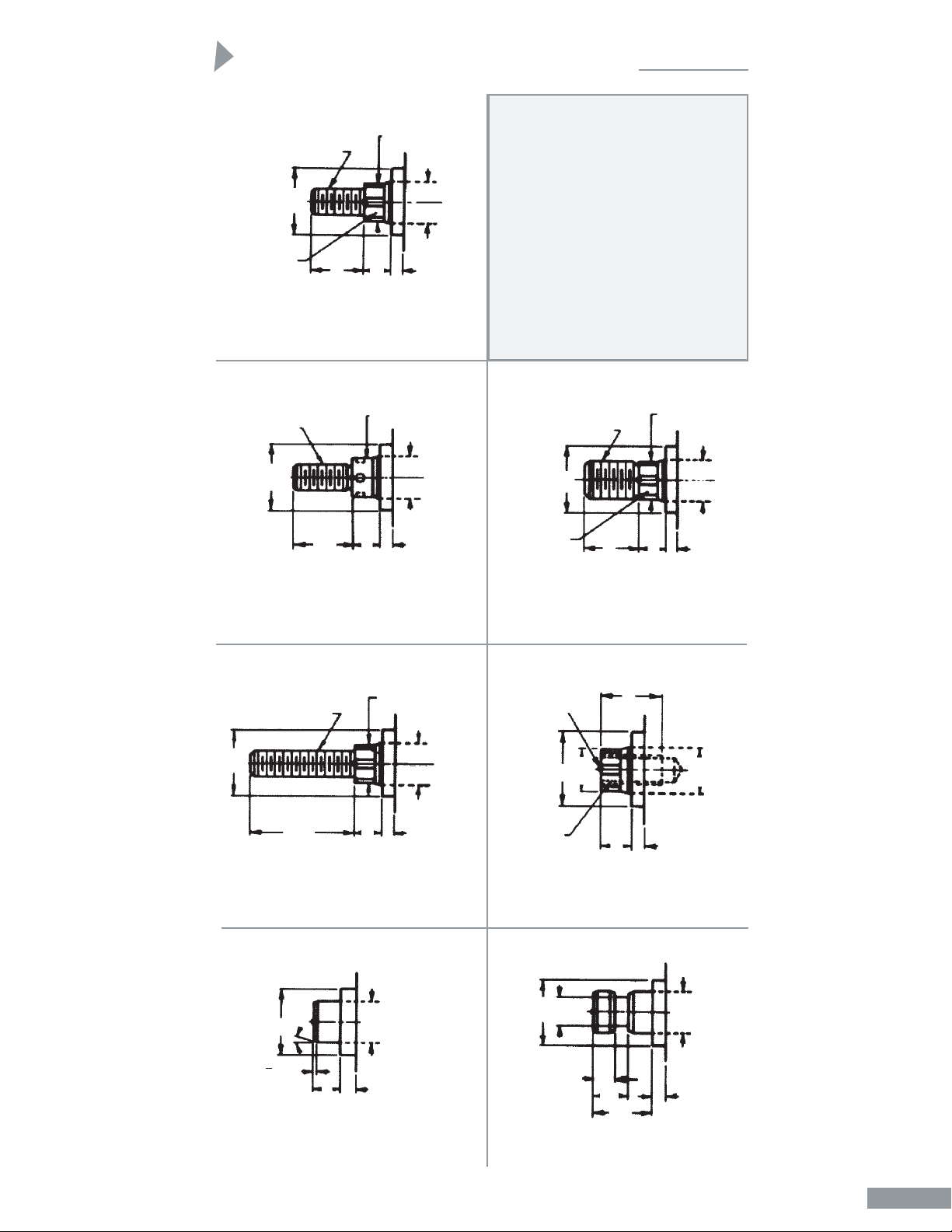
Rod End Information
Used with S.A.F.E. accessory (see
separate Accessories Brochure) for
fast, close radial alignment.
Female thread, used with male
accessories for shorter overall
cylinder length.
Male thread larger in diameter than
style 2. No shoulder for locking.
Stud not used.
Plain male Rod End with no threads.
Used for pushing, holding, knockouts, etc.
High Tensile, rolled thread stud with
two times A length is available on Rods
thru 2" in diameter.
Spanner Wrench Holes are provided
in lieu of Wrench Flats on larger Rod
sizes. See Rod End Dimensions on
opposite page.
IMPORTANT NOTE:
Style 2 Rod End is standard
and will be furnished unless
otherwise specified. Alternate
Rod End styles 1, 3, 4 and 6
are available at no extra
charge. Style 2X and other
special Rod End styles are
available for a nominal extra
charge. A wide selection of
Rod End accessories is shown
in separate Accessories
Brochure.
STANDARD – STYLE 2
Alternate – Style 1
Spanner Wrench Holes
in Lieu of Flats
Alternate – Style 3
Optional – Style 2X
Alternate – Style 4
Alternate – Style 6
KK THREAD
D
WRENCH
FLATS
D
WRENCH
FLATS
MM
DIA.
A
A
A
C
C
C
C
C
2xA
VA OR V
VA OR V
VA OR V
VA OR V
VA OR V
VA OR V
VA OR V
MM
DIA.
B
DIA.
NA
DIA.
NA
DIA.
NA
DIA.
NA
DIA
.
AF
DIA.
B
DIA.
20º
1
+ 1/16
8 - 0
B
DIA.
B
DIA.
B
DIA.
B
DIA.
B
DIA.
AE
AD
AC
MM
DIA.
MM
DIA.
MM
DIA.
MM
DIA.
MM
DIA
.
KK THREAD
1
/2" SPANNER
HOLES
KK THREAD
KK THREAD
CC THREAD
Male thread with adequate shoulder for
locking accessory. High tensile, rolled
thread stud used on all Rods thru 21/2"
in diameter.
C
A
4 WRENCH
FLATS
STANDARD
1
HH-22
Page 24
Just visit our Web Site:
www.sheffercorp.com
You don’t need to spend lengthy amounts of time figuring out what will
work best for your company. With our Cylinder Configurator, you can
easily find the ideal cylinder or actuator for your needs.
Visit our website and use the Cylinder Configurator demo. Register for
the Gold Program and download your results. It's free. You just need to
enter your specifications and performance parameters for your particular
project, then simply view and download your drawing or model in your
own CAD format. It’s that simple to generate your perfect match.
1
HH-23
Page 25
21⁄
2 HH FF 25 CC W
Policy:
The policy of the Sheffer Corporation is one of continual improvement in design and manufacture to assure still finer products, hence, specifications
are subject to change without notice.
Limited Warranty:
Sheffer warrants its products to be free from defects in material and workmanship for a period of one year from the date of shipment. This warranty
does not cover field labor charges for parts removal and replacement, adjustments, repairs or other work, corrosion, electrolysis, mineral deposits
or normal deterioration, misapplication, modification, or change in original operating conditions; components supplied by others; defects in parts
resulting from abuse, negligence, neglect, accident, fire or explosion, or seals and other components subject to normal wear.
The sole and exclusive remedy against Sheffer shall be for the repair or replacement of parts returned transportation prepaid to Sheffer’s factory
and found by Sheffer to be defective. Replacement parts provided shall not extend the warranty period for said parts or for the total unit.
IN CONSIDERATION OF THIS EXPRESS WARRANTY NO OTHER REMEDY (INCLUDING BUT NOT LIMITED TO INCIDENTAL OR
CONSEQUENTIAL DAMAGES) SHALL BE AVAILABLE. THIS WARRANTY SHALL BE IN LIEU OF ANY AND ALL OTHER WARRANTIES,
EXPRESS OR IMPLIED, INCLUDING, BUT NOT LIMITED TO, ANY IMPLIED WARRANTY OF MERCHANTABILITY OR FITNESS FOR A
PARTICULAR PURPOSE, AND OF ALL OTHER OBLIGATIONS ON THE PART OF SHEFFER.
Sheffer neither assumes, nor authorizes any person to assume for it, any other obligation or warranty.
Bore
As Required
Use Fractions
Where
Required
Cylinder Series Mounting
Listed Below
Stroke
As Required
Use Fractions Where
Required
Shown as Gross
Stroke Including
Dual Piston or
Stop Tube Length
Cushion
CF -- Cushion
Front
CR -- Cushion
Rear
CC -- Cushion
Both
Ends
Modification
A -- Variation in Ports
D -- Double Rod Extension
K -- Any Variation in Rod
from Standard. Any
Variation from Standard
Style 2 Rod End.
M -- Variation in Mounting
P -- NPT Ports
S -- Spring Return
V -- Viton Seals
W-- Water Fitted
Y -- Variation in
Construction
A
AA
CLA
CLH
C20
HH
MA
MH
Heavy Duty Pneumatic
200 PSI Pneumatic
Heavy Duty Pneumatic
Heavy Duty,
250 Pneumatic/
1500 Hydraulic
Heavy Duty Pneumatic,
Cast Iron
Heavy Duty Hydraulic
Medium Duty Pneumatic
Medium Pressure
Hydraulic
Mounting Styles
BX --
C --
CL --
EL --
FB --
FF --
FFX --
FH --
Basic Cylinder, Tie Rods
Extended, Both Ends
Clevis
Center Line Lug
End Lug
Foot Bracket
Front Flange
Front Flange, Extra Size
Front Head (7" thru 14" A
and MH - 16" thru 24" HH)
FHF --
FX --
NX --
P --
RF --
RFX --
RH --
Front Head Flange
Basic Cylinder, Tie Rods
Extended, Front End
Basic Cylinder, No Tie Rod
Extension
Pivot
Rear Flange
Rear Flange, Extra Size
Rear Head (7" thru 14" A
and MH - 16" thru 24" HH)
RHF --
RX --
SF -SL -SP --
T --
TF --
TR --
Rear Head Flange
Basic Cylinder, Tie Rods
Extended, Rear End
Side Flush
Side Lug
Sub Plate
Trunnion, Between Heads
Trunnion, Front
Trunnion, Rear
Order Information
To insure prompt delivery, please BE SURE TO INCLUDE THIS INFORMATION WHEN ORDERING:
1. Quantity
2. Series
3. Bore
4. Stroke - Gross Stroke always shown
in Model Number
5. Dual Piston or Stop Tube when
necessary - always give Gross and
Net Strokes
6. Mounting Style
7. Cushion (front, rear, both or none)
8. Rod End Style (if other than Style 2
standard)
9. Rod Size (standard, oversize or 2:1)
10. Extra Rod Extension (where required)
11. Port Size (if other than standard)
12. Port Positions other than standard
positions 1 and 5.
13. Cushion check, adjusting screw, and
bleed positions (when required) if
other than standard positions.
14. Medium (air, oil, water or other)
15. Type of fluid
16. Operating Pressure and Maximum
Shock Pressure
17. Temperature
18. Double rod extension (when
required)
19. XI dimension on all Trunnion
(between head) cylinders
20. Delivery required, or scheduling
Complete and correct ordering information will eliminate untimely delays. When in doubt, always contact local distributor or factory.
Contact distributor for helpful order or inquiry form.
COMPOSITION
Model Number
1
HH-24
Page 26
Conversions
Metric
Fraction Decimal (mm)
(inches) (inches) (x 25.4)
1
/64 .016 .4
1
/32 .031 .8
3
/64 .047 1.2
1
/16 .062 1.6
5
/64 .078 2.0
3
/32 .094 2.4
7
/64 .109 2.8
1
/8 .125 3.2
9
/64 .141 3.6
5
/32 .156 4.0
11
/64 .172 4.4
3
/16 .187 4.7
13
/64 .203 5.2
7
/32 .219 5.6
15
/64 .234 5.9
1
/4 .250 6.3
17
/64 .266 6.8
9
/32 .281 7.1
19
/64 .297 7.5
5
/16 .312 7.9
21
/64 .328 8.3
11
/32 .344 8.7
23
/64 .359 9.1
3
/8 .375 9.5
25
/64 .391 9.9
13
/32 .406 10.3
27
/64 .422 10.7
7
/16 .437 11.1
29
/64 .453 11.5
15
/32 .469 11.9
31
/64 .484 12.3
1
/2 .500 12.7
Fraction Equivalents
Metric
Fraction Decimal (mm)
(inches) (inches) (x 25.4)
33
/64 .516 13.1
17
/32 .531 13.5
35
/64 .547 13.9
9
/16 .562 14.3
37
/64 .578 14.7
19
/32 .594 15.1
39
/64 .609 15.5
5
/8 .625 15.9
41
/64 .641 16.3
21
/32 .656 16.7
43
/64 .672 17.1
11
/16 .687 17.4
45
/64 .703 17.9
23
/32 .719 18.3
47
/64 .734 18.6
3
/4 .750 19.0
49
/64 .766 19.5
25
/32 .781 19.8
51
/64 .797 20.2
13
/16 .812 20.6
53
/64 .828 21.0
27
/32 .844 21.4
55
/64 .859 21.8
7
/8 .875 22.2
57
/64 .891 22.6
29
/32 .906 23.0
59
/64 .922 23.4
15
/16 .937 23.8
61
/64 .953 24.2
31
/32 .969 24.6
63
/64 .984 25.0
1 1.000 25.4
F˚ C˚
-30 -34.4
-20 -28.9
-10 -23.3
0 -17.8
10 -12.2
20 -6.7
30 -1.1
40 4.4
50 10.0
60 15.6
70 21.1
80 26.7
90 32.2
100 37.8
110 43.3
120 48.9
130 54.4
140 60.0
150 65.6
160 71.1
170 76.7
180 82.2
190 87.8
200 93.3
210 98.9
220 104.4
230 110.0
240 115.6
250 121.1
260 126.7
C˚= (F˚- 32) ÷ 1.8
Temperature Equivalents
C˚ F˚
-30 -22
-20 -4
-10 14
0 32
5 41
10 50
15 59
20 68
25 77
30 86
35 95
40 104
45 113
50 122
55 131
60 140
65 149
70 158
75 167
80 176
85 185
90 194
95 203
100 212
105 221
110 230
115 239
120 248
125 257
130 266
F˚= C˚x1.8 +32
1
HH-25
Page 27
Distance Conversions
Inches cm mm
1 2.5 25.4
2 5.1 50.8
3 7.6 76.2
4 10.2 101.6
5 12.7 127.0
6 15.2 152.4
7 17.8 177.8
8 20.3 203.2
9 22.9 228.6
10 25.4 254.0
15 38.1 381.0
20 50.8 508.0
25 63.5 635.0
30 76.2 762.0
35 88.9 889.0
40 101.6 1016.0
45 114.3 1143.0
50 127.0 1270.0
55 139.7 1397.0
60 152.4 1524.0
65 165.1 1651.0
70 177.8 1778.0
75 190.5 1905.0
80 203.2 2032.0
85 215.9 2159.0
90 228.6 2286.0
95 241.3 2413.0
100 254.0 2540.0
cm = in. x 2.54
mm = in. x 25.4
Conversions
cm Inches
1 .4
2 .8
3 1.2
4 1.6
5 2.0
6 2.4
7 2.8
8 3.1
9 3.5
10 3.9
20 7.9
30 11.8
40 15.8
50 19.7
60 23.6
70 27.6
80 31.5
90 35.5
100 39.4
110 43.3
120 47.3
130 51.2
140 55.2
150 59.1
160 63.0
170 67.0
180 70.9
190 74.9
200 78.8
210 82.7
220 86.7
230 90.6
240 94.6
250 98.5
260 102.4
in. = cm x .394
Pressure Conversions
PSI Kg/cm2Bars
60 4.2 4.1
70 4.9 4.8
80 5.6 5.5
90 6.3 6.2
100 7.0 6.9
150 10.5 10.3
200 14.0 13.8
250 17.6 17.2
300 21.1 20.7
350 24.6 24.1
400 28.1 27.6
450 31.6 31.0
500 35.1 34.4
550 38.7 37.9
600 42.2 41.3
650 45.7 44.8
700 49.2 48.2
750 52.7 51.7
800 56.2 55.1
850 59.8 58.6
900 63.3 62.0
950 66.8 65.5
1000 70.3 68.9
1500 105.5 103.4
2000 140.6 137.8
2500 175.8 172.3
3000 210.9 206.7
3500 246.1 241.2
4000 281.2 275.6
4500 316.4 310.1
5000 351.5 344.5
Kg/cm2= PSI x .0703
Bars = PSI x .0689
Kg/cm
2
PSI Bars
4 56.9 3.9
5 71.1 4.9
6 85.3 5.9
7 99.5 6.9
8 113.8 7.8
9 128.0 8.8
10 142.2 9.8
20 284.4 19.6
30 426.6 29.4
40 568.8 39.2
50 711.0 49.0
60 853.2 58.8
70 995.4 68.6
80 1137.6 78.4
90 1279.8 88.2
100 1422.0 98.0
150 2133.0 147.0
200 2844.0 196.0
250 3555.0 245.0
300 4266.0 294.0
350 4977.0 343.0
400 5688.0 392.0
PSI = Kg/cm2x 14.22
Bars = Kg/cm
2
x .98
1
HH-26
Page 28

The Sheffer Corporation
6990 Cornell Road • Cincinnati, Ohio 45242
(513) 489-9770 • Fax: (513) 489-3034
sheffercorp.com
 Loading...