

Page 1

ELECTRONIC
POSITIONING CYLINDERS
Page 2
Electronic Positioning Cylinders
1
EP-1
Dead Zone The last 2.5 inches of the transducer rod
from the end of stroke to the end of the
rod. The magnet must not be permitted to
enter the dead zone, which causes an
unpredictable output.
Hysteresis The maximum error that can be expected
when returning to a point from the opposite direction.
Repeatability The ability to return to the same linear
measurement with the same direction of
travel. This is generally more important
than non-linearity for most applications.
Non-Linearity The deviation of the actual from the
theoretical position of the output signal.
For most applications the non-linearity is
considered the same as “Accuracy”.
Resolution The smallest increment of stroke that can
be detected and indicated on the output.
Null Space The distance from the transducer head face
and the start of the stroke.
Null Position The magnet position on the transducer rod
which produces a zero or minimum output
signal.
Stroke The active or sensing portion of the
transducer rod.
Analog Transducer output that yields 10-0 or 0-10 V
off two separate wires, where final voltage
output is proportional to the magnet position.
Digital Transducer output produces start/stop
signals with outputs in counts, square wave
in quadrature or parallel binary/BCD.
Terms
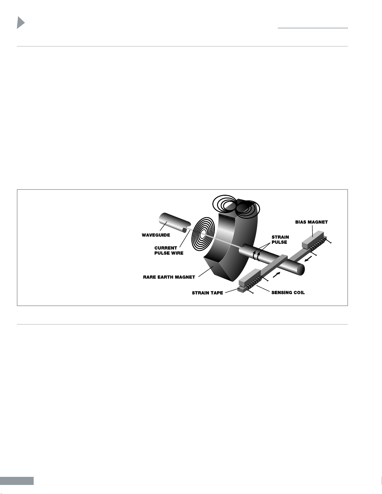
In MTS’ magnetostrictive sensor,
the interaction of two magnetic
fields induces a torsional strain
pulse in a waveguide. One field
emanates from a rare earth magnet; the other is generated by a
current pulse launched on a wire
inside the guide. Magnet position
is sensed by measuring the time
lapse between the launch of the
current pulse and the arrival of
the strain pulse.
Magnetostrictive Sensing
Performance Specifications
LDT (Linear Displacement Transducer)
Operating Voltage +13.5 to +24 Volts DC
Non-Linearity <+0.03% of full stroke or +0.05 mm
(+0.0002 inches), whichever is greater
Resolution 0.10 mm (0.004 inches) with on circu-
lation with 28 MHz counter (Digital)
infinite (Analog)
Hysteresis <0.02 mm (0.0008 inches)
Response Time (Analog) <3ms (Digital) Update 10,000
measurements per second
Measuring Range Analog (1-78 inches, US customary)
Metric 25-2000mm Digital (1-120 inches,
US customary) Metric 25-2000 mm
Operating Pressure 5,000 psi static; maximum 10,000 psi
spike Enclosure Designed to meet
NEMA 6
LRT (Linear Resistor Transducer)
Input Voltage 5-50 Volts DC
Non-Linearity 0.1% of total stroke up to 48 inches
1% of total stroke to 130 inches
Repeatability 0.001 inches
Life 500 million inches of travel
Velocity Hydraulic = 30 inches per second
Pneumatic = 50 inches per second
Output Analog, DC voltage only
Operating Pressure 5,000 psi maximum
Page 3
Electronic Positioning Cylinders
EP-2
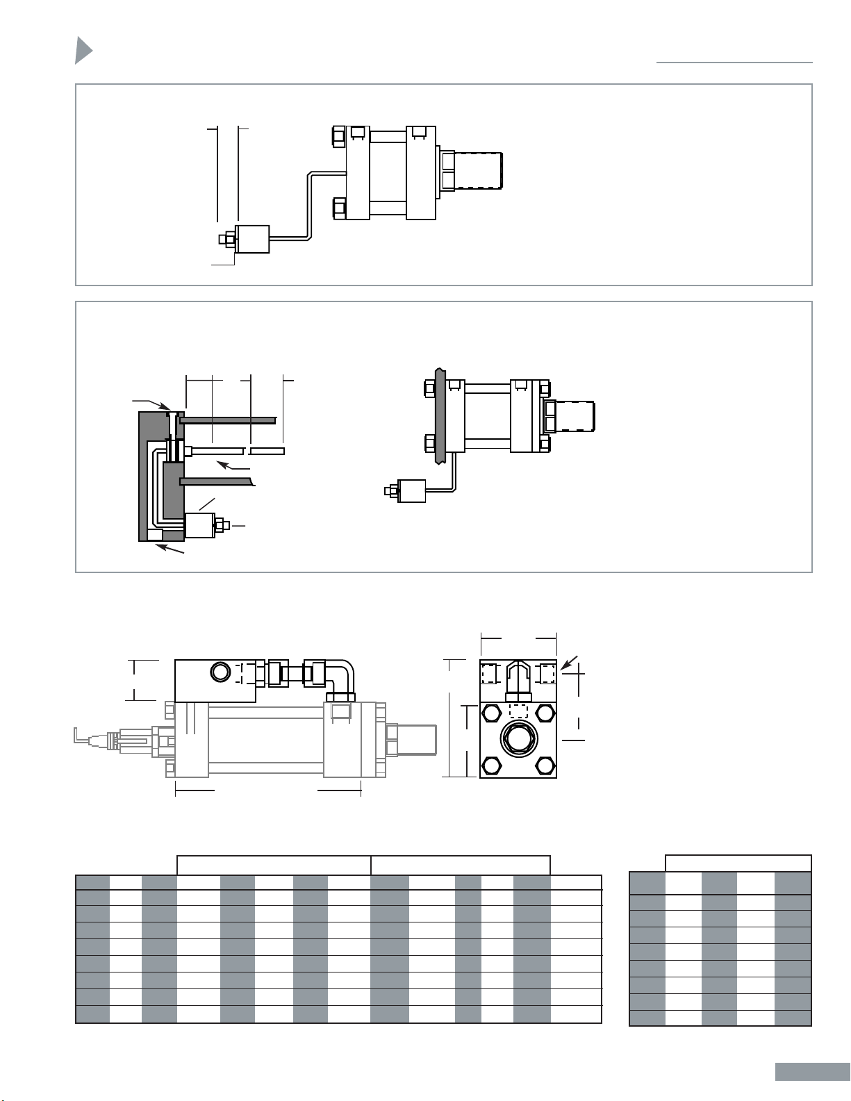
Mounting Possibilities for the LDT-LC Version
LDT-LC Without Manifold & Piping or Specific Mounting
MAXIMUM DISTANCE FROM CYLINDER IS 6" (152.49 MM)
CONNECTOR
DEPENDENT
MS CONNECTOR
31.09 MM (1.22")
RG CONNECTOR
29.06 MM (1.14")
RB CONNECTOR
MODEL LH ONLY
19.43 MM (.765")
RD INTEGRAL CABLE
31.75 MM (1.5")
9
/64 SOCKET HEAD
CAP SCREW
NOTE:
All mounting options are
available with the LDT-LC
version. See general catalogs
for series specific dimensions.
Some modifications may be
necessary. Please contact
factory for details on your
specific needs.
CONNECTOR HOUSING
SENSOR
RETAINING
SCREW
1/2" NPT PLUG
TEMPOSONICS LC
ELECTRONIC HOUSING
HIGH-PRESSURE TUBE
10.01 MM OD (.394")
DEAD ZONE
63.5 MM
(2.50")
ELECTRICAL
STROKE
NULL
25.4 MM
(1.0")
Electronic Housing may be
mounted anywhere with 6
inches of rear head such as in
a control panel, cool box or
on the machine. Note: The
interconnected cable is not
fully shielded and may be
susceptible to external noise.
When mounted as shown in
Example 1 the interconnect
cable is shielded by the cylinder end cap. When the LC
housing is mounted in an
alternative manner, proper
care must be taken to shield
the cable.
EXAMPLE 1 EXAMPLE 2
Valve Manifold Option
LDT cylinders have the transducer attached to the center rear
face of the cap. Any mounting
that does not interfere with the
center face of the cap can be
used with this standard design.
Note:
1. Minimum stroke is
required for piping installation. May use stop tube
to compensate this stroke.
2. Some manifold block will
extend beyond the side of
the rear cap on position
(2, 6). Contact engineering
for those sizes.
(3.7")
M
(4.8")
E
SQ.
PP
(PORTS)
N
LB + Minimum Stroke
NN
(1.50")
P
(2.6")
SIDE VIEW
ROD END VIEW
Use on DO3 & DO5 Use on DO8 Only
Bore E LB M N NN O P M N NN O P PP
2" 3" 45/8" 5" 2" 3" 13/8" 227/32" -10 SAE
21/2" 31/2" 43/4" 51/2" 2" 3" 13/8" 33/32" -10 SAE
31/4" 41/2" 51/2" 73/8" 27/8" 31/2" 11/8" 41/8" 71/2" 3" 5" 11/8" 311/16" -12 SAE
4" 5" 53/4" 77/8" 27/8" 31/2" 11/8" 43/8" 8" 3" 5" 11/8" 315/16" -12 SAE
5" 61/2" 61/4" 93/8" 27/8" 31/2" 11/8" 51/8" 91/2" 3" 5" 11/8" 411/16" -12 SAE
6" 71/2" 73/8" 1015/16" 37/16" 41/2" 11/2" 515/16" 113/16" 3 11/16" 5" 11/2" 53/8" -16 SAE
7" 81/2" 81/2" 1115/16" 37/16" 41/2" 0" 65/8" 123/16" 3 11/16" 5" 0" 531/32" -20 SAE
8" 9
1
/2" 91/2" 133/16" 311/16" 5" 0" 713/32" 137/16" 3 15/16" 5" 0" 639/64" -24 SAE
Minimum Stroke Required
Bore DO3 DO5 DO8 Servo
Valve
2" 4" 4"
21/2" 37/8" 37/8"
31/4"4
5
/8" 61/2" 45/8"
4" 43/8" 61/4" 43/8"
5" 37/8" 53/4" 37/8"
6" 33/4" 55/8" 33/4"
7" 31/4" 51/8" 31/4"
8" 2
1
/2" 43/8" 21/2"
Page 4
Electronic Positioning Cylinders
1
EP-3
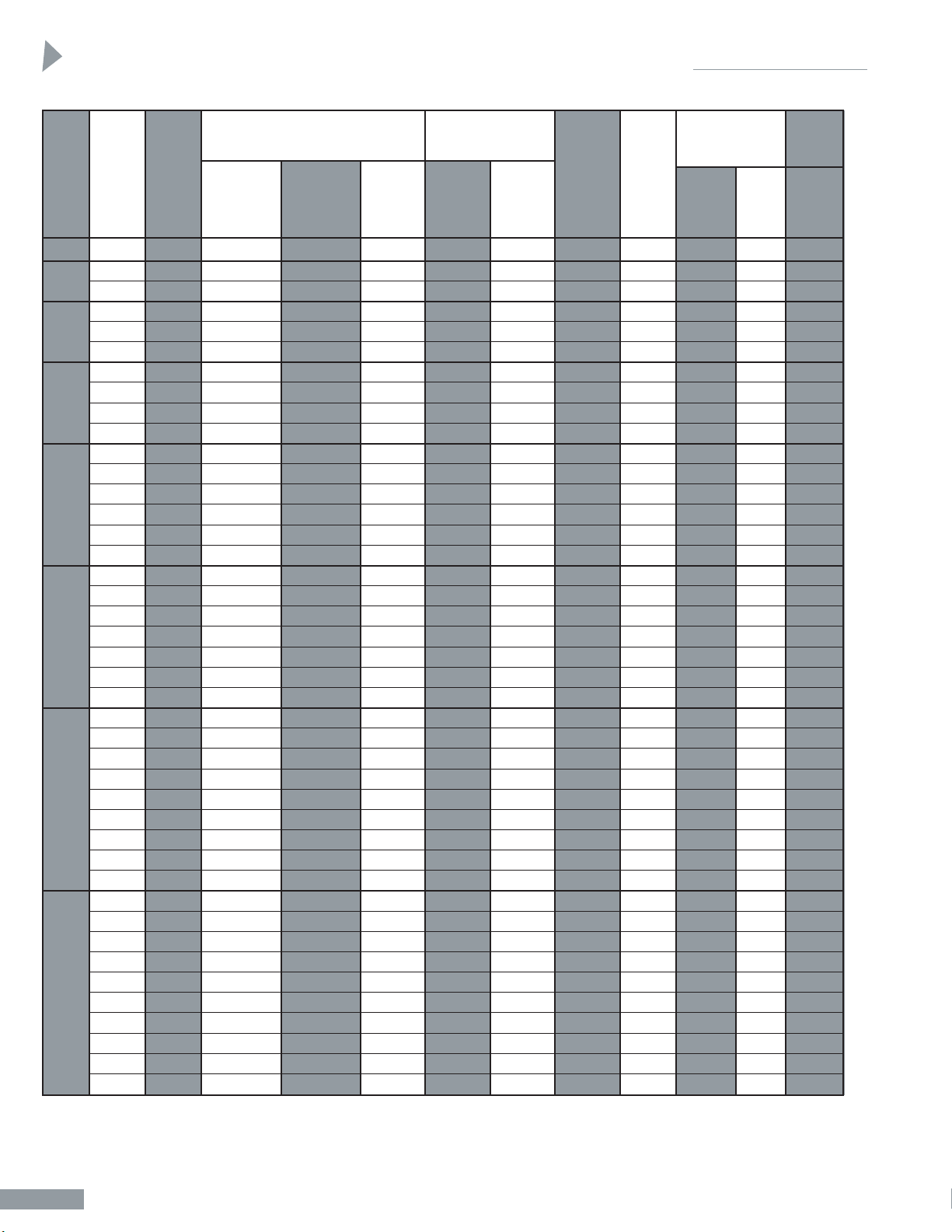
MH & A Series Cylinders
BORE ROD A THE AMOUNT
SIZE DIA. MALE ROD END FEMALE LB VL OF EXTRA PRESS
NOT STUDDED * ROD END (ADD PLAIN ROD RATING
STROKE) EXTENSION IN PSI**
CC KK STD. KK MIN. MALE FEMALE
THREAD THREAD WF THREAD WF ROD ROD PULL
END END STROKE
1 2 3 4 5 6 7 8 9 10 11 12 13
13/8 15/8 11/4-12 1-14 15/8 1-14 21/8 35/8 17/8 —
1
/2 2,450
13/8 15/8 11/4-12 1-14 15/8 1-14 2 33/4 17/8 —
3
/8 1,550
13/4 2 11/2-12 11/4-12 17/8 11/4-12 21/2 33/4 17/8 —
5
/8 1,550
13/8 15/8 11/4-12 1-14 15/8 1-14 15/8 41/4 15/8 — — 1,400
13/4 2 11/2-12 11/4-12 17/8 11/4-12 21/8 41/4 15/8 —
1
/4 1,400
2 21/4 13/4-12 11/2-12 2 11/2-12 23/8 41/4 15/8 —
3
/8 1,400
13/8 15/8 11/4-12 1-14 15/8 1-14 15/8 41/4 15/8 — — 925
13/4 2 11/2-12 11/4-12 17/8 11/4-12 21/8 41/4 15/8 —
1
/4 925
2 21/4 13/4-12 11/2-12 2 11/2-12 23/8 41/4 15/8 —
3
/8 925
21/2 3 21/4-12 17/8-12 21/4 17/8-12 3 41/4 15/8 —
3
/4 925
13/8 15/8 11/4-12 1-14 15/8 1-14 15/8 41/2 15/8 — — 675
13/4 2 11/2-12 11/4-12 17/8 11/4-12 17/8 41/2 15/8 — — 675
2 21/4 13/4-12 11/2-12 2 11/2-12 21/8 41/2 15/8 —
1
/8 1,075
21/2 3 21/4-12 17/8-12 21/4 17/8-12 21/2 41/2 15/8 —
1
/2 1,075
3 31/2 23/4-12 21/4-12 21/4 21/4-12 37/8 41/2 15/8 — 15/8 1,075
31/2 31/2 31/4-12 21/2-12 21/4 21/2-12 37/8 41/2 15/8 — 15/8 1,075
13/8 15/8 11/4-12 1-14 15/8 1-14 15/8 5 13/8 — — 525
13/4 2 11/2-12 11/4-12 17/8 11/4-12 17/8 5 13/8 — — 800
2 21/4 13/4-12 11/2-12 2 11/2-12 2 5 13/8 — — 800
21/2 3 21/4-12 17/8-12 21/4 17/8-12 21/2 5 13/8 —
1
/4 800
3 31/2 23/4-12 21/4-12 21/4 21/4-12 35/8 5 13/8 — 13/8 800
31/2 31/2 31/4-12 21/2-12 21/4 21/2-12 33/4 5 13/8 — 11/2 800
4 4 33/4-12 3-12 21/4 3-12 41/2 5 13/8 — 21/4 800
13/8 15/8 11/4-12 1-14 15/8 1-14 15/8 51/8 13/8 — — 380
13/4 2 11/2-12 11/4-12 17/8 11/4-12 17/8 51/8 13/8 — — 625
2 21/4 13/4-12 11/2-12 2 11/2-12 2 51/8 13/8 — — 625
21/2 3 21/4-12 17/8-12 21/4 17/8-12 21/2 51/8 13/8 —
1
/4 875
3 31/2 23/4-12 21/4-12 21/4 21/4-12 35/8 51/8 13/8 — 13/8 875
31/2 31/2 31/4-12 21/2-12 21/4 21/2-12 33/4 51/8 13/8 — 11/2 875
4 4 33/4-12 3-12 21/4 3-12 43/8 51/8 13/8 — 21/8 875
41/2 41/2 41/4-12 31/4-12 21/4 31/4-12 47/8 51/8 13/8 — 25/8 875
5 5 43/4-12 31/2-12 21/4 31/2-12 55/8 51/8 13/8 — 33/8 875
13/8 15/8 11/4-12 1-14 15/8 1-14 15/8 51/8 13/8 — — 290
13/4 2 11/2-12 11/4-12 17/8 11/4-12 17/8 51/8 13/8 — — 475
2 21/4 13/4-12 11/2-12 2 11/2-12 2 51/8 13/8 — — 675
21/2 3 21/4-12 17/8-12 21/4 17/8-12 21/2 51/8 13/8 —
1
/4 675
3 31/2 23/4-12 21/4-12 21/4 21/4-12 35/8 51/8 13/8 — 13/8 675
31/2 31/2 31/4-12 21/2-12 21/4 21/2-12 33/4 51/8 13/8 — 11/2 675
4 4 33/4-12 3-12 21/4 3-12 43/8 51/8 13/8 — 21/8 675
41/2 41/2 41/4-12 31/4-12 21/4 31/4-12 47/8 51/8 13/8 — 25/8 675
5 5 43/4-12 31/2-12 21/4 31/2-12 55/8 51/8 13/8 — 33/8 675
51/2 51/2 51/4-12 4-12 21/4 4-12 63/16 51/8 13/8 — 315/16 675
2
1
/2
2
3
1
/4
4
5
6
7
8
Page 5
Electronic Positioning Cylinders
EP-4
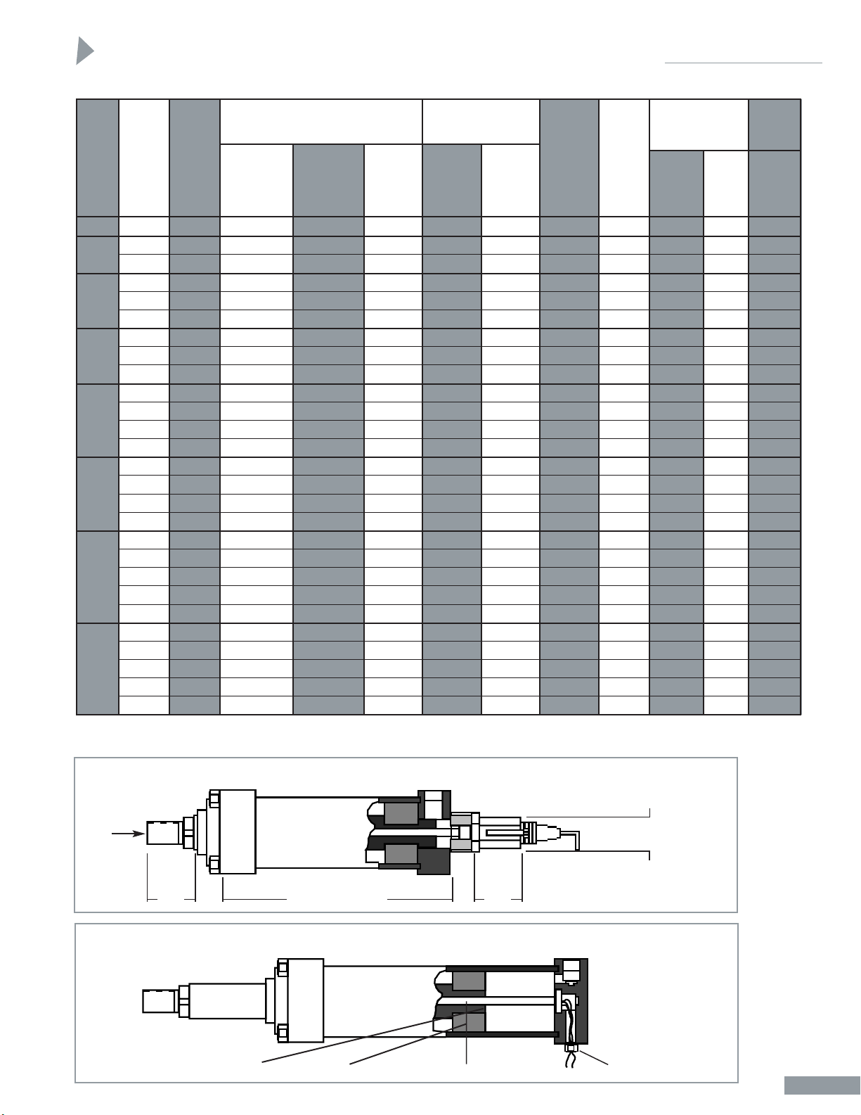
HH Series Cylinders
BORE ROD A THE AMOUNT
SIZE DIA. MALE ROD END FEMALE LB VL OF EXTRA PRESS
NOT STUDDED * ROD END (ADD PLAIN ROD RATING
STROKE) EXTENSION IN PSI**
CC KK STD. KK MIN. MALE FEMALE
THREAD THREAD WF THREAD WF ROD ROD PULL
END END STROKE
1 2 3 4 5 6 7 8 9 10 11 12 13
13/8 15/8 11/4-12 1-14 15/8 1-14 — 45/8 13/8 — — 3,000
13/8 15/8 11/4-12 1-14 15/8 1-14 — 43/4 13/8 — — 1,000
13/4 2 11/2-12 11/4-12 17/8 11/4-12 — 43/4 13/8 — — 3,000
13/8 15/8 11/4-12 1-14 15/8 1-14 — 51/2 11/8 — — 1,900
13/4 2 11/2-12 11/4-12 17/8 11/4-12 — 51/2 11/8 — — 1,900
2 21/4 13/4-12 11/2-12 2 11/2-12 — 51/2 11/8 — — 3,000
13/4 2 11/2-12 11/4-12 17/8 11/4-12 — 53/4 11/8 — — 2,275
2 21/4 13/4-12 11/2-12 2 11/2-12 — 53/4 11/8 — — 2,275
21/2 3 21/4-12 17/8-12 21/4 17/8-12 — 53/4 11/8 — — 3,000
2 21/4 13/4-12 11/2-12 2 11/2-12 — 61/4 11/8 — — 2,350
21/2 21/2 21/4-12 17/8-12 21/4 17/8-12 — 61/4 11/8 — — 2,350
3 31/2 23/4-12 21/4-12 21/4 21/4-12 — 61/4 11/8 — — 2,350
31/2 31/2 31/4-12 21/2-12 21/4 21/2-12 27/8 61/4 11/8 —
7
/8 3,000
21/2 3 21/4-12 17/8-12 21/4 17/8-12 — 73/8
1
/2 — — 2,820
3 31/2 23/4-12 21/4-12 21/4 21/4-12 — 73/8
1
/2 — — 2,820
31/2 31/2 31/4-12 21/2-12 21/4 21/2-12 — 73/8
1
/2 — — 2,820
4 4 33/4-12 3-12 21/4 3-12 23/4 73/8
1
/2 — 1' 3,000
3 31/2 23/4-12 21/4-12 21/4 21/4-12 — 81/2 — — — 3,000
31/2 31/2 31/4-12 21/2-12 21/4 21/2-12 — 81/2 — — — 3,000
4 4 33/4-12 3-12 21/4 3-12 — 81/2 — — — 2,875
41/2 41/2 41/4-12 31/4-12 21/4 31/4-12 25/8 81/2 — —
7
/8 1,900
5 5 43/4-12 31/2-12 21/4 31/2-12 35/8 81/2 — — 11/2 3,000
31/2 31/2 31/4-12 21/2-12 21/4 21/2-12 — 91/2 — — — 3,000
4 4 33/4-12 3-12 21/4 3-12 — 91/2 — — — 3,000
41/2 41/2 41/4-12 31/4-12 21/4 31/4-12 — 91/2 — — — 2,075
5 5 43/4-12 31/2-12 21/4 31/2-12 25/8 91/2 — —
3
/8 2,075
51/2 51/2 51/4-12 4-12 21/4 4-12 31/8 91/2 — — 1' 3,000
* For studded male rod end, use column 12 dimension instead of column 6.
** Pressure rating based on material yield strength with a 3:1 safety factor. For all other dimensions, see standard catalog for respective series.
21/2
2
3
1
/4
4
5
6
7
8
2.36 MINIMUM
CLEARANCE DIAMETER
3
7
⁄
8
LB PLUS STROKE
VL
WF
A
KK
or
CC
WIPER CARRIAGE ASSEMBLY
PISTON
LINEAR RESISTANCE ROD ASSEMBLY
ELECTRONIC CONNECTOR
LDT-LH Without Manifold & Piping
LRT Without Manifold & Piping
Page 6

Policy:
The policy of the Sheffer Corporation is one of continual improvement in design and manufacture to assure still finer products, hence, specifications are
subject to change without notice.
Limited Warranty:
Sheffer warrants its products to be free from defects in material and workmanship for a period of one year from the date of shipment. This warranty does
not cover field labor charges for parts removal and replacement, adjustments, repairs or other work, corrosion, electrolysis, mineral deposits or normal
deterioration, misapplication, modification, or change in original operating conditions; components supplied by others; defects in parts resulting from
abuse, negligence, accident, fire or explosion, or seals and other components subject to normal wear.
The sole and exclusive remedy against Sheffer shall be for the repair or replacement of parts returned transportation prepaid to Sheffer’s factory and found
by Sheffer to be defective. Replacement parts provided shall not extend the warranty period for said parts or for the total unit.
IN CONSIDERATION OF THIS EXPRESS WARRANTY NO OTHER REMEDY (INCLUDING BUT NOT LIMITED TO INCIDENTAL OR
CONSEQUENTIAL DAMAGES) SHALL BE AVAILABLE. THIS WARRANTY SHALL BE IN LIEU OF ANY AND ALL OTHER WARRANTIES, EXPRESS
OR IMPLIED, INCLUDING, BUT NOT LIMITED TO, ANY IMPLIED WARRANTY OF MERCHANTABILITY OR FITNESS FOR A
PARTICULAR PURPOSE, AND OF ALL OTHER OBLIGATIONS ON THE PART OF SHEFFER.
Sheffer neither assumes, nor authorizes any person to assume for it, any other obligation or warranty.
How to use this form:
1. Photocopy the Requirements List on page EP-6.
2. On your copy, fill in the blanks at each section with your requirements.
3. If you do not need what is offered in a section, please mark N/A in the blank.
4. If your requirement is not listed as a selection, please write in your requirement.
5. Once completed, contact your Sheffer distributor to fax requirements for price and
availability.
6. You may also go to the Sheffer web site at www.sheffercorp.com to obtain your distributor
name and additional information on contacting Sheffer.
Options (Consult Factory)
• Intrinsically safe
• Explosion proof
• Mill duty
• Strokes to 240"
• Special configurations
• Double piston/stop tube
• Rear protective housing
BX - Basic Cylinder, Tie Rods
Extended, Both Ends
C - Clevis
CL - Center Line Lug
EL - End Lug
FB - Foot Bracket
FF - Front Flange
FFX - Front Flange, Extra Size
FH - Front Head (7" thru 14" A
and MH–16" thru 24" HH)
FHF - Front Head Flange
FX - Basic Cylinder, Tie Rods
Extended, Front End
NX - Basic Cylinder, No Tie Rod
Extension
P - Pivot
RF - Rear Flange
RFX - Rear Flange, Extra Size
RH - Rear Head (7" thru 14" A
and MH–16" thru 24" HH)
RHF - Rear Head Flange
RX - Basic Cylinder, Tie Rods
Extended, Rear End
SF - Side Flush
SL - Side Lug
SP - Sub Plate
T - Trunnion, Between Heads
TF - Trunnion, Front
TR - Trunnion, Rear
Mounting Styles
Chart A
Page 7

Requirements List
1
EP-6
Photocopy This Page As Needed
Bore
As Required
Use Fractions
Where Required
Requirement
Model
HH Heavy-Duty Hydraulic
MH Medium-Duty Hydraulic
A Heavy-Duty Pneumatic
Requirement
Rod Diameter
1
3
/8 Min.
Requirement
Stroke
As Required
Use Fractions Where Required
Shown as Gross
Stroke Including
Dual Piston or
Stop Tube Length
Requirement
Cushions
CF Cushion Front
CR Cushion Rear
CC Cushion Both Ends
Requirement
Mounting
See Chart A
(Page EP-5)
Requirement
Feedback Mount
H Standard Rear Head Mount
D Detachable (MTS Only)
O Customer Supplied Feedback Device
C Rear Head Mount with Clevis Mount
& Enclosure
Requirement
Feedback Brand
FX Fitted for Customer Probe
MT MTS Standard LH
MC MTS Standard LC
BA Balluf Standard
GE Gemco Standard
Requirement
Feedback Type
1 LDT Analog Output
2 LDT Digital Output
3 LRT
4 None (Customer
supplied)
Requirement
Input
1 13.5 to 26.4 VDC
2 24 VDC
Requirement
Valve Mount
0 None Required
1 Servo Valve Manifold Base
(Customer to supply footprint)
2 Standard DO Pattern
(Please specify)
Requirement
Output
1 Analog 4-20 MA
2 Analog 0-10 VDC
3 Analog 20-4 MA
4 Analog 10-0 VDC
5 Digital RS422 PWM
6 Digital RS422 P/P
7 Digital Binary
Requirement
Connector
RG Standard 7 Pin Micro
RB 10 Pin Threaded Connector
MS 10 Pin Bayonet Style
RO Integral Cable Pigtail
Connection
HO Integral Cable with Heavy-
Duty Jacket (Specify length)
Requirement
For any questions on base cylinder, refer
to specific brochure or visit our web site at
www.sheffercorp.com
Page 8

The Sheffer Corporation
6990 Cornell Road • Cincinnati, Ohio 45242
(513) 489-9770 • Fax: (513) 489-3034
sheffercorp.com
 Loading...