

Page 1
Wireless Lighting Control
Z-Wave
3-way Wall Mount Relay Switch
Z-Wave® Certified
Wireless Lighting Control
45609
Page 2
Introduction:
Thank you for your purchase o f a GE Z-Wave® co ntrol devic e.
Z-Wave technology is designed to automate lighting/home
control and pr ovide easy remote operatio n of all y our Z-wa ve
enabled devices. The GE Z-Wave product family includes a
variety of devices to control lighting in your home. It is up to
you whether you want to control one room or your entire house
and whether you want to do it all now or start with one room and
add more over time.
This wall mount relay switch is one component of a Z-Wave®
control system and is designed to
work with all other Z-Wav e ena bl ed
devic e s i n a hom e control network. It
will also act as a wireless repeater to
insure that commands intended for
another device in the network are
received, thereby extending the
range of the wireless contro ller .
Z-Wave de vic es of other types and
brands can be added to the system
and will also act as rang e
extend ers if th ey support this
function of repeating the
signal received to other
nodes in the system.
Page 3
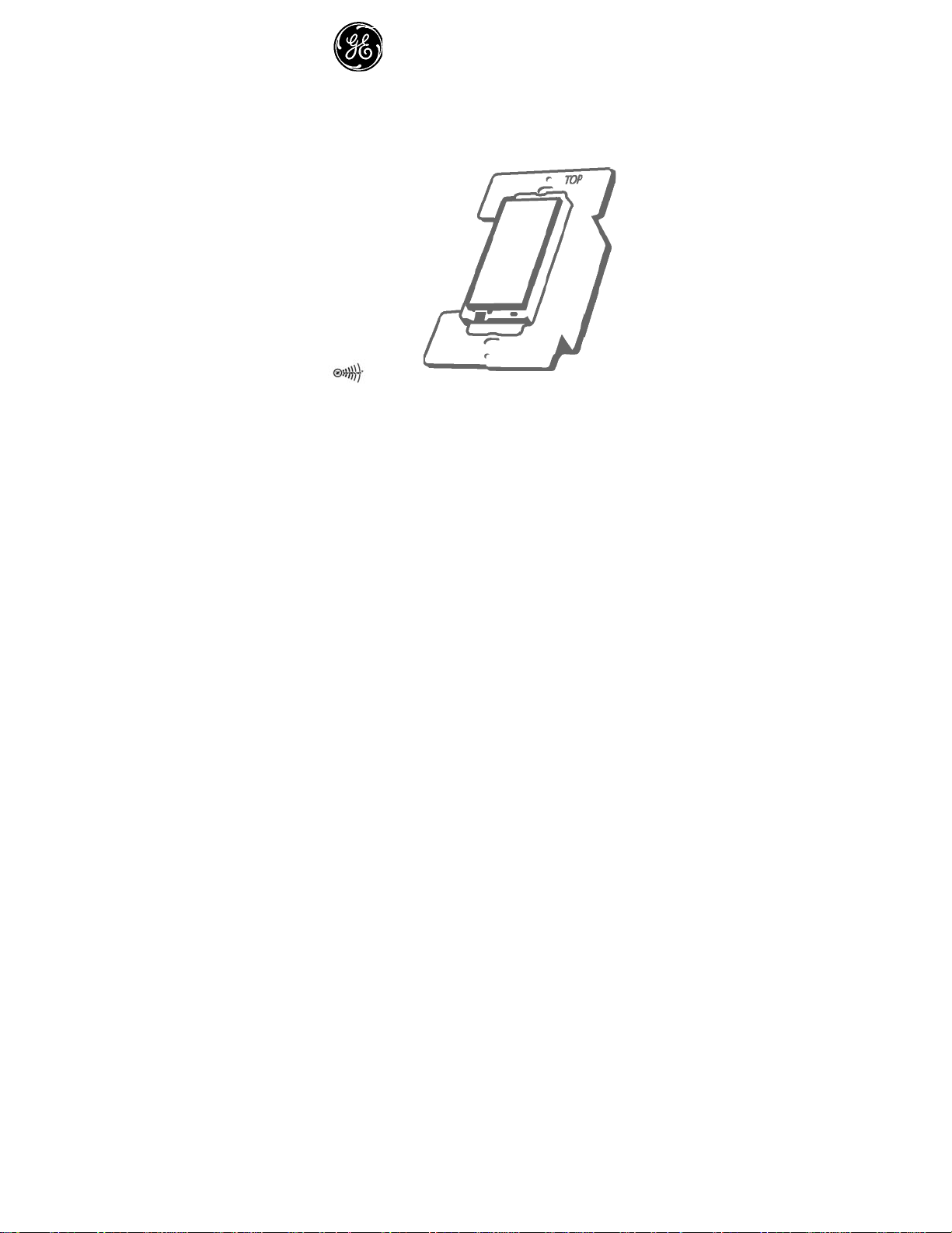
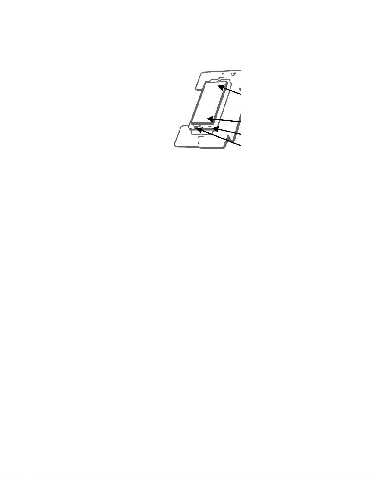
This wall mount relayswitchis designed for use
only with permanently installed incandescent
lighting fixtures. The incandescent lighting controlled
by this switch must not ex ceed a total of 600 watts.
There are no user serviceable parts in this unit.
Push ON
Push OFF
LED light
Air gap switch
Page 4

The Load-Sense feature on this Z-w ave product will turn the power
to the connected device ON when a change in the load is detected.
Z-wave connected devices should always be disconnected before
performing any service or maintenance of the devices.
Controlling Appliances:
Exercise extreme caution when us ing Z-Wave devices to control
appliances. Operation of the Z-Wa ve device may be in a different room
than the controlled appli ance, also an u nintentio nal activati on may occur
if the wrong button on the remote is pressed. Z-Wave devi ces m ay
automatically be pow ered o n due to tim ed ev ent pr ogram min g.
Depending upon the appliance, these unattended or unintentional
operations could possibly result in a hazardous condition. For these
reasons, we recommend the following:
1. Assign Z-Wave controlled appliances to device numbers 10 –
18 on the GE remote. The likelihood of unintentionally turning
on the appliance will be reduced significantly because the
“Shift” button w ill nee d to be pr esse d bef ore pre ssin g devic e
numbers 10-18.
2. Z-Wave devices controlling appliances should be removed
from “All” control setting. Instructions on how to do this are
included in the manual for your GE remote.
3. Do Not include Z-Wave devices in Groups or Scenes if they
control appliances.
4. Do Not use Z-Wave devices to control electric heaters or any
other appliances which may present a hazardous condition due
to unattended or unintentional or automatic power on control.
5. Double check programs for accuracy before using them.
WARNING
RISK OF FIRE
RISK OF ELECTRICAL
SHOCK RISK OF BURNS
Page 5

Wireless Range
This device complies with the Z-Wave standard of open-air, line of
sight transmission distances of 65 feet. Actual performance in a home
depends on the number of walls between the remote controller and the
destination device, the type of cons tructi on and th e number of Z-Wav e
enabled devices installed in the control network.
GE Z-Wave Network
Every Z-Wave enabled device acts as a signal repeater and multiple devices
result in more possible transmission routes which helps eliminate “RF
dead-spots”.
Things to consider regarding RF range:
- Each wall or obstacle (i.e.: refrigerator, big screen TV, etc.) between the
remote or a Z-Wave device and the destination device will reduce the
maximum range of approximately 25-30%.
- Brick, tile or concrete walls block more of the RF signal than walls made of
wooden studs and plasterboard (drywall). - Wall mounted Z-Wave devices
installed in metal junction boxes will suffer a significant loss of range
(approximately 20%) since the metal box blocks a large part of the RF
signal.
Page 6

Effects of Home Construction on Wireless Range Between
Z-Wave Enabled Devices.
Note:
The distances shown in the ta ble below are ty pical exam ples.
Actual performance in your hom e will vary. From the Remote (or
repeating Z-Wave module) to destination device:
Type of Construction
Wood Frame Brick, Tile or w/Drywall Concrete
Plastic
J-Boxes*
0**
100’ 80’ 100’ 80’
Number of
walls or
obstacles
* For Plug-in Modules or In-Wall D evices Install ed in Plast ic Junction
Boxes
** Line of Sight / no obstruc tions
1
70’ 56’ 60’ 48’
2
49’ 39’ 36’ 29’
34’ 27’ 21’ 17’
3
Metal
J-Boxes
Plastic
J-Boxes*
Metal
J-Boxes
Page 7

Please Note: Z-wave home control networks are de signed to w ork
properly alongside 802.11 w ireless com puter networ ks, Blueto oth an d
other 2.4GHz or 5.8GHz devices. Some baby cams, wireless video devices
and older cordless phones using the 900MHz frequency range may cause
interference and limit Z-Wave func tionality . Many 900MHz p roduc ts
have a switch to select channel “A” or “B”. You may find that one of these
channels will cause less interference than the other.
Installation
This Z-wave relay switch may be used in new installations or to replace
an existing wall switch. A wall plate is not included. You may be able to
re-use your existing wall plate if you are replacing a standard decorator
style switch. If this is a new installation or your existing wall plate can
not be used, we recommend the use of a mid-sized, decorator style wall
plate. These are available at most home centers or hardware stores.
See diagram on next page.
Page 8

Typical Switch Wiring Schematic
w
Line
Load
Neutr al
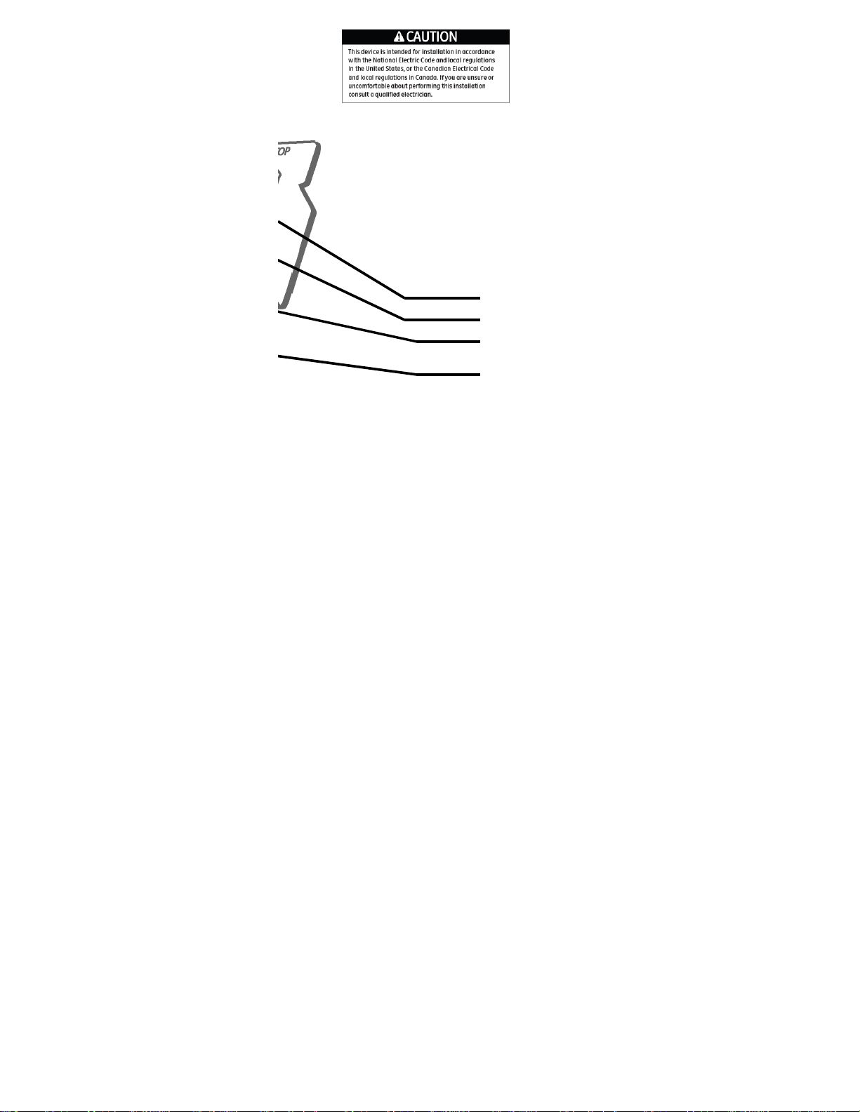
Correct Auxiliary Switch Position Schematic
Line
Black
Traveler
Yello
Auxiliary
White
Neutral
Primary
Green
Load
Neutral
Page 9

1. Shut off power to the circuit at fuse box or circuit breaker.
2. Remove wall plate. ! Warning: Verify power is OFF to switch
box before continuing.
3. Remove the switch mounting screws.
4. Carefully remove the switch from the switch box. DO
NOT disconnect the wires.
5. Identity the wiring in the box and decide if this will be the
location for the Auxiliary Switch or the Z-Wave Relay Switch.
6. Mark the wiring so it can be identified properly later.
7. Disconnect the wires from the existing switch.
8. Insert either the Auxiliary or the Z-Wave Relay Switch as
shown in the Typical Wiring Schematic or Correct Auxiliary
Position Schematic.
9. Insert the new Z-Wave Switch into the switch box being
careful not to pinch or crush wires.
10. Secure the switch to the box using the supplied screws.
11. Mount the wall plate.
12. Repeat Steps 2 through 11 for the second switch.
13. Reapply power to the circuit at fuse box or circuit breaker and
test the system.
Page 10

You should now be able to use the r ocker to manually turn On/Off the
connected lighting.
Use your primary controller to include the relay switch in the home
control network after the switch is wired as shown in the above diagram,.
It can then be added to groups and/or lighting scenes and managed
remotely to control the On/Off status of the connected incandescent
lighting.
Air Gap Switch
During normal operation, there is a sm all amount of power passin g
through the switch to the load e ven when the Z -Wave swit ch is turned off.
The 45609 has an air gap switch on the lower left side (see diagram for
locati on) to com ple tel y d isco nne ct power to the load. Pull the air gap switch
OUT to disconnect the power while replacing light bulbs and push it all the
way back in for normal operation. The air gap switch must be not all the way
to control the lighting.
Key Features
- Remote On/O ff c ontro l via t he Z- Wav e controller/netw ork
- Manual On/Off control with the front panel rocker
- Load-Sensing turns the light O N if the switc h on the connecte d device is
used instead of the remote or t he front pane l rocker
- LED indicates switch locatio n in a dark room
BASIC OPERATION
The connected light can be turned ON i n three ways:
1. With a remote
2. Manually with the push button on the Z -Wave switc h
3. By the Load-Sensing feature. Normally, the Z-W ave unit controls
the ON/OFF state of the connected dev ice and power is eit her
turned
Page 11

ON or OFF at the Z-Wave switch (either m anually or by the remote).
If the switch on the connected lig ht is used, th e Z-Wave control
circuitry automatically senses that the lig ht is being turned ON and
activates the Z-Wave controlle d outlet, pro viding power to t he
connected device. This feature is disabled by default; See the
section on advanced operation for i nstructions on how to enable i t.
Remote Control
GE Z-wave remotes provide control of an Individual device, Groups of
devices and Scenes. Other brands of Z-Wave Certified remotes may not
offer as much flexibility in how you can set up your lighting control
network. Please refer to your remote control’s instructions for details on its
capabilities and instructions for adding and controlling devices.
Manual Control
The 45609 wall mount relay switc h allows the user to:
Turn ON/OFF the connected incandescent lighting.
- To turn the connected lighting ON : Tap the top of the rocker.
- To turn the connected lighting OFF: Tap the bottom of the rocker.
Program your Light Switch (Include or exclude the Z-Wave
switch from the Z-Wave home control network.)
- Refer to the instructions for your prim ary control ler to access
the network setup function a nd include or ex clude devices.
- When prompted by your primary controller, tap the top or bottom of
the rocker.
- The primary controller shou ld indicate tha t the action wa s
successful. If the controller indicates the action was unsuccessful,
please repeat the procedure.
- Once the wall mount relay switc h is part of the network, th e same ba si c
procedure is used to add the wall mount relay switch to groups & scenes or
Page 12

change advanced functions. Refer t o the primary controller’s instruc tions
for details.
Please Note: After a power failure, the 45609 wall mount relay
switch returns to its last used ON/OFF state.
LED Indicator
The LED will be lit when the connected lighting is OFF.
This is the factory default setting and can be changed if your
primary controller supports the node configuration function (see
Advanced Operation below)
ADVANCED OPERATION
The following Advanced Operation parameters require that you
have an advanced controller like the model 45601 Advanced remote.
Advanced remotes from other manufacturers may also be able to
change these settings; however, basic remotes do not have this
capability.
All On/All Off
Depending upon your primary controller, the 45609 wall mount relay
switch can be set to respond to ALL ON and AL L OF F commands in up
to four different ways. Some controllers may not be able to change
the response from its default setting. Please refer to your controller’s
instructions for information on whether or not it supports the
configuration function and if so, how to change this setting. The four
possible responses are:
1. It will respond to ALL ON and the A L L OF F command
(default).
2. It will not respond to ALL ON or ALL OFF comma nds.
3. It will respond to the ALL OFF command but will not respond
to the ALL ON command.
4. It will respond to the ALL ON command but will not respond
to the ALL OFF command.
Load Sensing
Load sensing in disabled w hen shippe d from the factory . This feature can
Page 13

be enabled if desired. Setting parameter 2 9 to a value of 1 wil l enable the
load Sense function.
- Parameter No: 29
- Length: 1Byte
- Valid Values = 0 or 1 (default 0)
Note: When replacing a burned-out light bulb, the load sensing
feature (if enabled) will automatically turn the light ON when the
new bulb is installed even if the Z-wave module was turned OFF.
LED Light
When shipped from the factory, the LED on the 45609 is set to turn ON
when the connected light is turned OFF. This allows the LED to
indicate the switch’s location in a dark room. To make the LED turn
ON when the light is turned ON, change parameter 3’s value to “1”.
- Parameter No: 3
- Length: 1 Byte
- Valid Values = 0 or 1 (default 0)
Invert Switch
If the wall mount relay switch is accidentally installed upside
down with “On” at the bottom and “Off” at the top, the default On/Off
rocker settings can be reversed by changing parameter 4’s value to
“1”.
- Parameter No: 4
- Length: 1 Byte
- Valid Values = 0 or 1 (default 0)
Restoring Factory Defaults
All Configuration Parameters ca n all be rest ored to their factory default
settings by using your master c ontroller to r eset the device.
Interoperability with Z-Wave
™
A Z-Wave
network can integrate device s of various c lasses, and the se
TM
Devices
Page 14

devices can be made by different m anufacturer s. Although e very Z-Wave
certified product is designed to work with all o ther Z-Wave cer tified
products, your controller m ust include the ap propriate de vice
classifications in order to contro l non-ligh ting Z-wave devices. As an
example, the 45600 basic remote is designed only for controlling Z -Wave
devices using the lightin g control class ification. The 4 5601 deluxe rem ote
with LCD readout can control ot her Z-Wave certif ied devices l ike
thermostats as well as lighti ng.
WARRANTY
JASCO Products warrants this produc t to be free from manufacturing
defects for a period of two years from the original da te of consumer
purchase. This warranty is limited to the repair or replacement of this
product only and does not ex tend to conse quential or incidental damage to
other products that may be used with thi s product. T his warranty is in lieu
of all other warranties, expres sed or implie d. Some state s do not allow
limitations on how long an im plied warran ty lasts or perm it the exclusi on
or limitation of incidental or co nsequentia l damage, so the a bove
limitations may not apply to you. This warra nty give s you specific ri ghts,
and you may also have other ri ghts which vary from state to st ate. Please
contact Customer Service at 800- 654-8483 ( option 4) betw een 7:30AM –
5:00PM CST or via our website (www.jascoproducts.com
should prove defective within the warranty period.
JASCO Products Company
Building B
10 E Memorial Rd. Oklahoma City , OK 73114
) if the unit
FCC ID: U2Z45609
The Federal Communication Commission Radio Frequency
Interference Statement includes the following paragraph:
The equipment has been tested and found to comply with the
limits for a Class B Digital Device, pursuant to part 15 of the FCC
Page 15

Rules. These limits are designed to provide reasonable protection
against harmful interference in a residential installation. This
equipment uses, generates and can radiate radio frequency
energy and, if not installed and used in accordance with the
instruction, may cause harmful interference to radio
communication. However, there is no guarantee that interference
will not occur in a particular installation. If this equipment does
cause harmful interference to ra dio or television re ception, which
can be determined by turning the equipment off and on, the user is
encouraged to try to correct the interference by one or more of the
following measures:
- Reorient or relocate the receiving antenna
- Increase the separation between the equipment and receiver
- Connect the equipment into an outlet on a circuit different
from that to which the receiver is connected
- Consult the dealer or an experien ced radio/TV technician f or help
Operation is subject to the following two conditions:
-
This device may not cause interference
- This device must accept any interference, including interference
that may cause undesired operation of the device.
Importan t N ote : To com ply with the FCC RF exposure compliance
requirements, no change to the antenna or the device is permitted. Any
change to the antenna or the device could result in the device exceeding
the RF exposure requirements and void user’s authority to operate the
device.
Page 16

Compliance with IC Rules and Re gulations
IC ID: 6739B-45609
Jasco Products Company
Model: 45609
This Class B digital device complies with Canadian ICES-003.
SPECIFICATIONS
Power: 120 VAC, 60 Hz.
Signal (Frequency): 908.42 MHz.
Maximum Load: 600W, incandescent lam ps on ly,1/2 HP Motor or
1800W (15A) Resistive.
Range: Up to 100 feet line of sight between the Wireless Controller and
the closest Z-Wave receiver module.
Operating Temperature Range: 32-104° F (0-40° C)
For indoor use only.
Specifications subject to change without notice due to continuing
product improvement
Z-Wave is a registered US trademark of Z ensys A/S
© 2007 JASCO Products Company
Page 17

is a registered trademark of General E lectric
Company and is used under license to Jasco Products
Compa ny LL C, 10 E Memorial Rd., O klahoma C it y,
Oklahoma 73114
Made in China
All brand names shown are tradem arks of their
respective owners.
 Loading...