

Page 1

SHAWDIRECT DIGITAL SATELLITE TV
Dual Satellite Installation Manual
MULTIPLE AWARD-WINNING
24/7/365SERVICE
Page 2
Your simple guide
Your simple guide
to simple installation.
to simple installation.
Your ultimate television experience is here! Simply follow the steps
outlined in this manual to install your system and you’ll be enjoying
amazing 100% digital satellite TV in no time. Before you begin,
we’d like to better acquaint you with Shaw Direct.
With over 490 channels and growing, including your favourites
in HD, Shaw Direct provides flexible programming options to suit
every customer. We also provide 24/7/365 award-winning customer
support for any of your questions. Our 100% Canadian service team
is happy to help you at one of our three call centres in Calgary,
Mississauga and Montreal.
Here are a few of the great things you'll enjoy as a
Shaw Direct customer:
TAKE A VACATION FROM YOUR BILL
When you go on holidays so can your bill, with our seasonal
disconnect program.
UNIQUE ELLIPTICAL DISH
Get the power of two satellites in one, plus great reception,
rain or shine.
EXTENSIVE FREE PREVIEWS
Over 30,000 hours of previews per year so you can sample before
you buy.
We also offer accessories to enhance your experience, like:
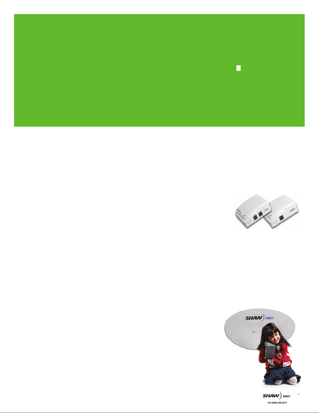
SHAW DIRECT’S WIRELESS EASY JACK
Turn any electrical outlet into a phone jack, and connect your
receiver to order Pay Per View movies and events, right from
your remote!
Here’s why it’s handy:
■ Caller ID/Call Waiting compatible
■ Built-in surge protection
■ Eliminates the cost and challenge
of hard-wiring a new phone jack
■ Also works with other devices
such as computers, phones and faxes
If you want to hear about customer offers and promotions, sign-up
for our free email news at SHAWDIRECT.CA/SCOOP. And tune into
channel 299 where you’ll also find technical tips and movie
and sports highlights.
Welcome to the Shaw Direct family!
SIMPLE SATELLITE™ WARRANTY
A lifetime warranty on external equipment.
NO LONG-TERM CONTRACTS
You don’t have to worry about a big commitment.
2
Page 3
1. GETTING STARTED
3
0
20
10
40
5
0
60
This Shaw Direct Installation Manual provides all of the
information required to setup your satellite system. The manual
provides step-by-step instructions, however skills in construction,
wiring and assembly will also be required to successfully complete
the installation.
IMPORTANT: We do not recommend installing the satellite dish on your roof,
unless absolutely necessary. If you choose to mount the dish on the roof,
we strongly recommend consulting a building or construction expert
before installation.
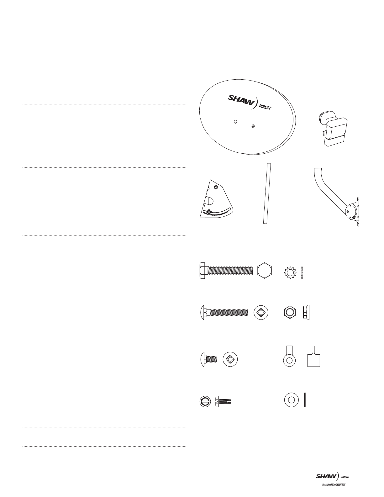
Your Shaw Direct Dish Kit contains the following components:
■ Shaw Direct 60 cm Elliptical Dish with dual satellite hardware
(see images for complete inventory).
60 CM ELLIPTICAL DISH
IMPORTANT: Read this manual thoroughly before you start.
WARNING: All satellite dish systems must be properly grounded, particularly
if the dish is close to or above the roof line. Improper grounding can result in
damage or serious personal injury. National, provincial and local electrical
codes may require you to ground the dish directly and to insert a grounding
block in the coaxial cables running from the dish to the receiver inside the
building. Before beginning installation, carefully read the section on grounding
the dish (see section 10).
This installation requires you to:
■ Use hand tools such as a drill
■ Determine whether water pipes, electrical wiring or gas lines
are close to the installation area
■ Route coaxial cable through walls and under floors
■ Use a compass, protractor and carpenter’s level
■ Use a ladder to climb structures
■ Know your local, provincial and national grounding codes
If you do not have the experience to perform these tasks,
contact SHAW DIRECT for assistance.
You will need the following tools:
■ #1 Philips screwdriver
■ 7/16 hex wrench, open or combination end
■ Electric drill and bits
■ Carpenter’s level
■ Compass
■ Protractor
CLAMP MOUNT
AS SEMBLY
HARDWARE
1/4˝x 1-1/2˝ Long Hex Head Bolt
(Feed Support Arm Mounting)
1 Supplied
1/4˝ x 1-3/4˝ Long Carriage Head Bolt
(Antenna Mounting Bolt - Painted Head)
2 Supplied
1/4˝ x 1/2˝ Carriage Head Bolt
(Mast Adjusting Bolts)
2 Supplied
SATELLITE FEED
SUPPORT ARM
1/4˝ External Tooth Washer
2 Supplied
1/4˝ Whiz Nut
(Hex Head)
5 Supplied
Spacer Sleeve
(Feed Support Arm Mounting)
1 Supplied
QUAD LNB
UNIVERSAL
MOUNT
AS SEMBLY
If you are installing a 75 cm dish, you will also require:
■ 2 - 13 mm wrenches (one to hold and one to tighten)
■ A wind brace support is recommended for high wind areas
NOTE: You must use the mast that came with the dish.
Hex Head Hi/Lo Screw
2 Supplied
1/4˝ Flat Washer
3 Supplied
3
Page 4
Key points to remember when installing your Shaw Direct System:
■ Do not drill any holes until you’ve confirmed the best location for the dish.
■ Make sure the installation of the dish conforms to local electrical and
building codes, zoning requirements and other applicable laws and
regulations. If you are unsure, contact a local electrician or building
inspector for assistance.
■ For possible periodic removal of snow, choose a site that is easily
accessible.
■ Ensure there are no visible obstructions between the dish and your line of
sight to the satellites. Keep in mind that trees will grow up and outward and
may eventually block the signal.
■ The maximum allowable length for the RG-6 coaxial cable connecting
the receiver to your dish is 125 feet. Consult Shaw Direct if the cable will
exceed this length.
■ Use only RG-6 grade coaxial cable. Using lower grade RG-59 coaxial cable
may result in excessive signal loss and poor reception. Cable grade type is
indicated on the outer jacket of the cable.
Do not install the dish:
■ Under power lines
■ Where it may be easily tampered with
■ Where it is exposed to high winds, during windy or stormy conditions
2. MOUNTING LOCATIONS
Your dish will typically be mounted on a solid base. To ensure your
dish doesn’t move in windy conditions, choose a location where it
can be securely fastened. The mounting surface should be rigid
and solid.
We do not recommend:
■ Mounting the dish on a railing
■ Installing the dish on aluminum or vinyl siding (these are unlikely to be
structurally sound)
Keep grounding requirements in mind (see section 10 for additional
information on grounding).
NOTE: We do not recommend mounting the dish on the roof unless absolutely
necessary. We also recommend that you consult a building expert for future tips
on preventing roof leakage.
3. DISH ASSEMBLY
ST EP 1: To avoid losing any hardware components, select a clear
area for dish assembly.
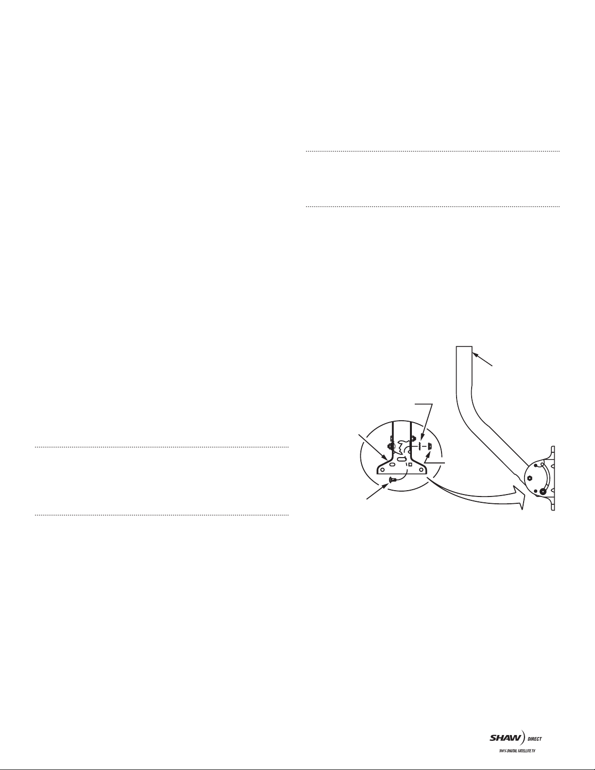
Step 2: On the Universal Mount, insert the (2) 1/4˝ X 1/2˝ Carriage
Head Bolts (Mast Adjusting Bolts), through the mast and the
curved slot of the mount. Capture with (2) 1/4˝ External Tooth
Washers and (2) 1/4˝ Whiz Nuts. Tighten the bolts just enough to
hold in place (see Figure A).
FIGURE A
Ass emble Mas t Adjus ting Bolts w ith Whiz Nut loose
enough to allow movement in curved slot, without
damage to painted surface.
1/4˝ External Tooth Washer,
both sides
Universal
Mount
Universal
Mount
Assembly
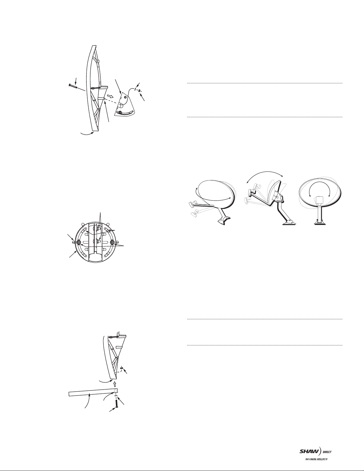
IMPORTANT: The Elliptical Dish has a turn radius of +/- 35 degrees. If you are
mounting the dish on the side of your house, check the assembled dish and
mounting pole to see if you can rotate the dish in the desired azimuth setting.
If you can’t rotate the dish, choose an alternate location.
Key things to remember when choosing a mounting location:
■ The mounting surface should be flat, even and in good condition.
■ If you install the dish on the roof or side of your house, be sure to attach
the bolts into a building stud, rafter or other solid surface.
■ When mounting on the roof of your house, use an adequate/approved
sealant (for your type of roofing material) around the holes where the base
of the universal mount meets the mounting surface. This will prevent the
roof from leaking. Consult with a roofing expert to confirm best sealant.
1/4˝ Whiz Nut
1/4˝ x 1/2˝ Carriage Head Bolt
(Mast Adjusting Bolt)
Step 3: Attach the dish to the Clamp Mount Assembly using the
(2) 1/4˝ X 1-3/4˝ Long Carriage Head Bolts (Antenna Mounting
Bolts-Painted Head), (2) 1/4 Flat Washers and (2) 1/4˝ Whiz Nuts.
Ensure the Center Pivot Pin on the Clamp Mount Assembly is
inserted in the mating hole of the Dish (see Figure B).
4
Page 5
30
20
10
4
0
50
60
FIGURE B
1
4
0
1
3
0
1
2
0
1
1
0
1
0
0
8
0
7
0
6
0
5
0
4
0
S
K
E
W
S
K
E
W
9
0
4. LOCATING THE SATELLITE
1/4˝ x 1 3/4˝ Long
Carriage Head Bolt
(Antenna Mounting Bolt)
Clamp Mount
Assembly
1/4˝ Flat Washer
1/4˝ Whiz Nut
Dish Socket
Centre Pivot Pin
STEP 4: Before tightening the bolts, adjust the skew alignment to
the 90 degree mark on the Clamp Mount Assembly (see Figure C).
Tighten the bolts just enough to hold in place. You’ll have to make
further adjustments to this setting later.
TIP: Initially setting the skew to 90 degrees will make it easier to
aim the dish.
FIGURE C
Skew Alignment Mark
Azimuth Clamp Bolts
Boss Holes
ST EP 1: Determine the direction in which to point the dish.
The primary satellite (SAT A) is located at 107.3 west longitude; the
secondary satellite (SAT B) will be located at 111.1 west longitude.
IMPORTANT: For dual satellite (elliptical) dish installation, use the SAT B
Azimuth, Elevation and Skew listings in the Dual Satellite Locator Chart at the
back of this manual for the city nearest your location.
WRITE THEM HERE:
Azimuth Elevation Skew
SAT A: _________ SAT A: _________ SAT A: _________
SAT B: _________ SAT B: _________ SAT B: _________
FIGURE E
SKEWELE VATIONAZIMUTH
NOTE:
Skew Adjustment Nuts
Each Scale mark
is 2 degrees
STEP 5: Attach the Feed Support Arm to the dish using the (1) 1/4˝ X
1-1/2˝ Hex Head Bolt (1), Spacer Sleeve, (1) 1/4˝ Flat Washer and
(1) 1/4˝ Whiz Nut, making sure the Feed Support Arm and Spacer
Sleeve are positioned as shown (See Figure D). Position the 2 plastic
cable clips (packaged with the LNB) around the support arm to
secure the coax cable(s) from the LNB to receiver.
FIGURE D
Feed Support Arm
Dish Socket
Spacer Sleeve
1/4˝ x 1 1/2˝ Long Hex Head Bolt
1/4˝ Whiz Nut
Flat 1/4˝ Washer
STEP 2: Use a compass to determine roughly where to point your dish.
STEP 3: Choose a dish installation location with a clear line of sight
to both SAT B and SAT A based on the settings you recorded
earlier. There should be no trees, buildings or other obstructions
between the dish and the satellite. Do you have a clear line of sight
to both SAT A and SAT B?
■ If YES, go to Step 4 and continue with the installation.
■ If NO, find another location.
■ If you’re not sure, contact Shaw Direct for more information.
NOTE: To ensure an accurate compass reading, stay away from large metal
objects. To double-check accuracy, take multiple readings several feet apart.
STEP 4: At the dish install site, hold a compass level and still in the
palm of your hand. When the needle stops rotating (dark half of the
needle always points north), slowly rotate the body of the compass
so that the “N˝ marking is aligned with the dark half of the needle.
Locate the tick mark on the compass edge corresponding to the
SAT B azimuth number you wrote down earlier (see Figure F). This
is the direction in which to point your dish to receive both SAT A
and SAT B signals.
TIP: Use a stick or other object to mark the correct azimuth direction.
YOU’VE JUST FINISHED ASSEMBLING THE DISH.
5
Page 6

0
180˚
90˚
270˚
FIGURE F
30
20
1
0
40
50
60
30
20
1
0
40
50
60
90°
60°
30°
0°
If you live in Vancouver,
the satellite will be to the Southeast.
If you live in Newfoundland,
the satellite will be to the Southwest.
STEP 5: Estimate the SAT B elevation (angle) setting you recorded
earlier, using a protractor if needed (see Figure G). Check any
obstructions at that elevation. If there are obstructions, then select
an alternate location for the dish.
FIGURE G
0 degrees is straight toward the horizon
and 90 degrees is straight upward.
IMPORTANT: When evaluating the install location, make sure there are no trees,
branches or objects visually obstructing the dish and the general direction
of the satellite. Also, keep in mind that trees grow up and outward and may
eventually block the signal.
FIGURE H
Level Not Level
Use bubble level to plumb mast so it is
vertical in all directions.
Curved Slot
STEP 2: Drill holes in the structure on which you are mounting the
dish to match the holes in the base of the Universal Mount.
STEP 3: Secure the Universal Mount with appropriate surface screws.
Check the mount for movement. An improperly secured mount will
affect dish performance.
STEP 4: Slide the Dish/Clamp Mount Assembly onto the mast by
loosening the (2) Azimuth Clamp Bolts (see Figure C) and the
Elevation Pivot Bolt just enough to slide the assembly until it
makes contact with the Elevation Pivot Bolt (see Figure I). Tighten
the Elevation Pivot Bolt just enough to hold it in place on the mast.
YOU HAVE JUST COMPLETED LOCATING A SITE FOR YOUR DISH.
5. ATTACHING THE DISH
ST EP 1: Ensure mast is plumb before drilling any holes. Hold the
Universal Mount in place on the mounting area. Use a carpenter’s
level to plumb the antenna mast’s straight section. If the bubble
levels (horizontal and vertical) are not centered, rotate the mast
(in the curved slot) until it is plumb. Lock it in place by securely
tightening the Mast Adjusting Bolts (see Figure H).
IMPORTANT: Alignment of the dish will be difficult if the mast is not plumb.
FIGURE I
Use t he metal edge, not the nut o r L-bracke t to set e levation.
(For example, in this picture, the elevation is set at 26).
When adjusting
elevation, use edge of metal
to line up with elevation setting
for your area on the elevation scale.
Elevation
Indicator
Elevation Pivot Bolt
Elevation
Adjustment
Bolt
STEP 5: Loosen the Elevation Adjustment Bolt 1/3 turn from tight
on either side of the Clamp Mount Assembly. Adjust the Clamp
Mount Assembly to the edge of the white indicator line per the
SAT B elevation setting you recorded earlier. Tighten the Elevation
Adjustment Bolt (see Figure I).
STEP 6: Attach the Quad Satellite LNB/Feedhorn Clamp Assembly to
the Feed Support Arm. Loosen the Feed Arm screw enough to allow
the clamp to fit snugly into the Feed Support Arm. Securely tighten
the Feed Arm screw.
6
Page 7

STEP 7: Using your compass, point the LNB in the direction
corresponding to the SAT B azimuth setting (see Figure J).
Draw a vertical mark overlapping the Clamp Mount Assembly and
the mast. This mark will provide you with the approximate satellite
location reference point when you are ready to tune to the satellite.
FIGURE J
STEP 8: Loosen the Skew Adjustment Bolts on either side of the Clamp
Mount Assembly. Adjust the Skew Alignment Mark with the scale
indicator to the SAT B skew setting you recorded earlier. Finally, lock
it in place by securely tightening the Skew Adjustment Bolts.
IMPORTANT: Do not make any further adjustments to the Skew Setting from this
point onward.
STEP 9: After making the permanent skew adjustment, install the (2)
Hex Head Hi/Lo Screws in the dish boss holes (see Figure C). Four
boss holes are available but you’ll only need to use two (the other
two may be obstructed depending on the skew setting). Do not over
tighten Hi/Lo Screws.
STEP 1: Connect the RG-6 coaxial cable provided with the install kit
to one of the ports of the QUAD LNB. Connect the other end of the
coaxial cable to the satellite receiver input connector. To make the
dish alignment easier, we suggest you temporarily locate the receiver
and TV at an electrical outlet close to where the dish is installed.
Unless you can view the signal level on the TV screen from where
the dish is being aligned, you will require an assistant to monitor the
signal level reading on the TV as you align the dish.
STEP 2: When the receiver is first powered up, it should be tuned to
channel 299. If you are using a legacy receiver and cannot tune to
channel 299, go to channel 284 instead.
If you are working with an
non-activated legacy receiver,
you should see the following
displayed on the TV when
you first turn the receiver on.
Using the remote, tune receiver
to channel 284 to align the
dish. If the receiver has been
activated before, tune to channel
299 (not 284).
For new or non-activated
Advanced receivers, you
should see the following
displayed on your TV when you
first turn the receiver on. Tune
to channel 299 if the receiver
is not already there.
Non-activated legacy receivers.
Advanced receivers.
YOU HAVE JUST FINISHED ATTACHING THE DISH TO THE UNIVERSAL MOUNT.
6. CONNECTING RECEIVER AND DISH
You are now at the point in the installation where one of the output
ports of the QUAD LNB needs to be connected to the Shaw Direct
satellite receiver. Connect the receiver to a TV to see a relative
scaled signal level meter that will assist you in obtaining maximum
signal strength. If you are unsure of how to connect the TV to the
receiver, refer to the User Guide that came with your receiver.
STEP 3: Access the Installation Settings menu. To access this menu
on legacy model receivers:
1. Using the remote, press Options
2. Press 6: System Setup
3. Press 3: Installation settings
4. Press 1: Tune in Satellite Signal
Position the yellow cursor
on the Provider ID (using
navigator keys on the remote
control) and enter 4128
on the keypad.
Installer Menu for legacy model receivers.
7
Page 8

To access this menu for on Advanced model receivers:
1. Using the remote, press Options
2. Press 6: System Setup (if available)
3. Press 4: System Settings
4. Press 3: Installation Settings
5. Press 1: Tune in Satellite Signal
STEP 5: Standing behind the dish, using both hands, grasp the dish
on each side and slowly move the dish in very small increments to
the east or west (several degrees) while your assistant observes the
TV installation menu for increases in signal strength.
STEP 6: As you start to get an indication of increasing signal, make
a second reference mark on the dish clamp and pipe mast to serve
as a point where signal strength increased.
Installer menu for Advanced receivers.
Position the yellow cusor on EMM Provider ID (using navigator
keys on the remote control) and enter 4128 on the keypad. Use the
above illustrated installer menu to align the dish for maximum
signal strength. You should have the assistance of a second person
to monitor the TV while you complete the adjustments to the
satellite dish. As you align the dish for optimum signal strength,
the signal level bar will increase in length from left to right and
will change colour from red (no signal) to yellow (marginal signal)
to green (good signal). Continue to align the dish until you achieve
maximum strength. Under clear sky conditions and depending on
your location, you should be able to achieve a signal strength
of between 80 and 90%. In addition to the visual signal strength
indicator, the receiver also emits an audio beeping that will
increase in speed as signal strength increases and will become
a monotone once you have aligned the dish to the satellite and
achieved approximately 50% signal strength. When audio beep
becomes monotone, the front panel signal LED should change
from Red to Green, indicating signal lock on the satellite.
7. ALIGNING DISH TO ACQUIRE
SHAW DIRECT SIGNAL
With the receiver on and your assistant ready to monitor signal
strength on the TV, you are now ready to make adjustments to the
dish to acquire the Shaw Direct satellite signal.
STEP 7: As you move dish past
the point of maximum signal
strength, move dish back in
the opposite direction until
you achieve maximum signal.
STEP 8: Tighten the dish clamp screws.
STEP 9: Now make small adjustments to the elevation of the dish to
see if you can further improve on the signal strength. Loosen the
Elevation Adjustment Bolts and make slight adjustments (1/2 degree
increments) in the elevation, finding the maximum signal strength.
When you’ve located the maximum signal strength possible, securely
tighten all bolts.
STEP 10: As a last step, adjust the skew of the dish according to the
skew setting you recorded for the location where you are installing
the dish. Again, make small adjustments as your assistant monitors
the signal strength. When you have reached maximum signal
strength tighten the screw to lock down the skew setting.
NOTE: Do not be discouraged if you do not acquire signal on your first attempt.
Be patient and try again. Recheck the pipe mast for true vertical 90 degrees.
Once you acquire signal, you may need to make very small adjustments to the
dish compass heading (azimuth), elevation and skew settings to maximize signal
strength to between 80 and 90%.
ST EP 1: Refer to the azimuth, elevation and skew settings for the
location that you recorded on Page 5.
STEP 2: For initial alignment, set the skew to 90 degrees. Skew will
be readjusted to your specific location setting once you acquire the
Shaw Direct satellite signal.
TIP: It is easier to locate satellite signal with skew set to 90 degrees.
STEP 3: Check that the dish elevation is set to the elevation setting
listed for your area.
STEP 4: Draw a reference mark on the dish clamp and pipe mast as
a starting point before you make any adjustments to the dish.
SIGNAL VERIFICATION
The front panel of the satellite receiver will indicate if the correct
Shaw Direct signal is being received. On the receiver, observe the
LED signal status indicator light. Once this light is no longer red, it
indicates the receiver is tuned to a valid channel and has acquired
the Shaw Direct signal.
You are ready to proceed to the next step.
If this LED light is RED it indicates NO SIGNAL is being received
by the receiver. The dish is not properly aligned to receive the Shaw
Direct satellite signal.
8
Page 9

AUTHORIZING RECEIVER FOR SERVICE
If your receiver installer menu displays signal strength of between
80 and 90%, you have successfully aligned the dish to the Shaw
Direct satellite.
Congratulations, you are now ready to authorize your receiver for
programming. Record the receiver serial number (SN) and receiver
unit address (UA) from the bar code label on the back panel of the
receiver or from the bar code label that is applied to the receiver’s
shipping carton. Record these numbers below for future reference.
SN (16 digits) _________________________
UA, 0 0 0 – 0 __ __ _ _ __ - _ _ __ __ _ _ __ - _ _ __ __
8. FINE TUNING
STEP 1: Call Shaw Direct at 1.888.554.7827 to authorize your
receiver for programming.
9. ALTERNATE TUNING METHOD
FIGURE K
Shaw Direct will ensure the correct channel map is set for your
receiver and verify the reception of both satellites. After your
receiver has been activated, you can fine tune the dish to ensure
maximum signal strength on all channels.
While speaking with the Shaw Direct representative, ask for a
reference channel from each satellite to use when fine tuning the dish.
STEP 2: Tune to the first reference channel provided and access the
Installation Settings menu as described in Section 6.
FINE TUNING THE AZIMUTH:
STEP 3: With your assistant monitoring the signal level, move the dish
back and forth slightly (about a millimeter at a time) to attempt to
acquire the highest reading possible on the signal strength meter.
STEP 4: Once you have found the maximum signal strength, lock the
azimuth rotation position in place by tightening the Azimuth Clamp
Bolts (see Figure C).
NOTE: Fine tuning to a high signal strength reduces signal interference in adverse
weather conditions and ensures optimal reception from both satellites. Although
the signal level bar goes to a maximum of 99, you will not reach this level.
FINE TUNING THE ELEVATION:
STEP 5: Loosen the Elevation Adjustment Bolts and make slight
adjustments (1/2 degree increments) in the elevation, finding the
maximum signal strength, as you did in the azimuth tuning process.
You may prefer to locate the satellites using a SF-100 Satellite
Finder (see Figure K), a standalone satellite signal finding meter
which can be purchased separately from Shaw Direct or your Shaw
Direct retailer.
ST EP 1: Connect a short coaxial cable from the LNB terminal on the
Satellite Finder to the Quad LNB. Connect the receiver terminal on
the meter to a coaxial cable, which in turn connects to the SAT IN
port on the Shaw Direct receiver.
STEP 2: Tune to channel 299 (Advanced receivers). If you have
a non-activated legacy receiver, tune to channel 284.
NOTE: For satellite finder and LNB to function, they must be connected to a
satellite receiver, plugged in and turned on.
STEP 3: Adjust the dish as closely as possible to the elevation and
azimuth settings you recorded earlier.
STEP 4: Move the dish azimuth rotation very slightly to the right of
the reference mark you drew on page 5.
STEP 5: Slowly rotate the dish back toward the reference mark and
and listen for pitch changes in the audible tone. If your elevation is
set correctly, you should hear two major pitch changes as it picks
up the satellite signals. A weak first change of pitch may be the
wrong satellite. Continue rotating the dish until the second major
deflection, which will be SAT A (107.3), your intended target.
STEP 6: Exit the Installation Settings menu and tune to the second
reference channel provided. Go back into the Installation Settings
menu and repeat steps 3-5 to maximize signal strength from the
second satellite.
STEP 7: When you’ve located the highest signal possible on both
channels, securely tighten ALL bolts
YOU HAVE JUST COMPLETED FINE TUNING. Skip ahead to section 10.
STEP 6: When you have located both signals, move the dish slightly
to the right and left of the mark until you’ve maximized the signal.
Then tighten the Azimuth Clamp Bolts. Verify you’ve located the
correct satellite (see Signal Verification on page 8).
9
Page 10

STEP 7: While listening to the meter, apply gentle pressure to the top
of the dish to move the dish – first slightly downward, then upward
to see if you can increase the signal strength further. Carefully
adjust the elevation until you’ve maximized the signal. Tighten the
Elevation Adjustment Bolts.
STEP 8: Follow the steps described in Fine Tuning (Section 8) to
obtain the highest reading possible on the signal strength meter.
STEP 9: The dish should now be peaked to its maximum. Remove
the Satellite Finder and plug the LNB directly into the receiver.
Confirm the signal strength by checking the on-screen signal
strength meter, as described in the previous section.
YOUR SYSTEM IS NOW FINE TUNED.
10. GROUNDING THE COAXIAL CABLE
The Shaw Direct dish kit includes the following items to ground the
outdoor coaxial cable:
■ Coax Cable Connector Grounding Block
■ Grounding Wire
■ Grounding Clamp
FIGURE L
Grounding Block
Outdoor coaxial cable that may be subject to static discharge
or contact with electrical wiring must be grounded through a
grounding block located as close as possible to the cable entry
point (see Figure L).
■ Run the Grounding Wire for the coaxial cable from the Grounding Block
connector to a cold water pipe nearest the cable entry point.
■ Wrap the copper grounding strap around the cold water pipe. Tighten the
strap using a bolt and secure the ground wire under the binding post nut,
as illustrated below.
IMPORTANT: For more information on grounding, refer to the receiver’s
User Guide included with your Shaw Direct system.
11. TROUBLESHOOTING
IF YOU ARE HAVING TROUBLE FINDING THE SATELLITE
SIGNAL, TRY EACH OF THE FOLLOWING:
■ The cable can be plugged into any of the 4 available ports on the quad LNB,
but must be plugged into the SAT IN port on the Shaw Direct receiver.
■ Make sure all cables are secure and re-verify your azimuth, elevation and skew
setting for your location. The settings straight section must be plumb.
■ Adjust the elevation by +1 degree from the settings you recorder earlier
and repeat the steps in Section 7 to acquire Shaw Direct signal.
■ Adjust the elevation by –1 degree from your original settings you recorded
earlier and repeat the steps in Section 7 to acquire Shaw Direct signal.
■ Ensure cables are connected properly at the grounding block.
IF YOU CANNOT CHANGE CHANNELS, TRY THE FOLLOWING:
■ Unplug the receiver, wait 30 seconds and plug it back in. Turn on the
receiver and try selecting channel 299 with your remote (Advanced
receivers).
try 284.
If you still can’t select or acquire signal on 284 or 299, call us at
1.888.554.7827 for further assistance.
If you have a legacy receiver and cannot access channel 299,
Ground block (shown with
2 coax cable feeds and ground
wire secured to binding post)
10
Page 11

SATELLITE LOCATOR CHART
Satellite Look Angles are listed for both Satellite A (107.3W longitude) and Satellite B (111.1W longitude). The reception of satellite signals in
areas with a dish elevation less than 12 degrees may not be possible. Consult with a Shaw Direct retailer in your area. All information is listed
in degrees.
NOTE: Please refer to the SATELLITE B settings if you have an elliptical dish. SATELLITE A should only be used for a round dish.
SATELLITE A SATELLITE B
Town/ City
Compass
Azimuth
Dish
Elevation
Dish
Skew
Compass
Azimuth
Dish
Elevation
Dish
Skew
NEWFOUNDLAND
Bonavista 264 14.4 126 267 12.1 127
Cartwright 262 13.8 120 265 11.9 121
Corner Brook 260 17 124 263 14 .8 125
Gander 263 15 125 266 12.8 126
Grand Falls 262 15 .7 125 265 13.5 126
Hebron 259 13.6 114 262 12 115
Indian Harbour 262 13.6 119 265 11.7 120
Labrador City 251 19.1 116 254 1 7.3 11 8
Nain 258 14 .4 116 262 12.7 117
North West River 259 15 .5 119 262 13.6 120
Nutak 259 13.8 115 262 12.2 116
Placentia 263 15.5 127 266 13. 2 128
Port aux Basques 258 18 .5 125 262 16 .2 126
Rigolet 2 61 14. 3 119 264 12.4 120
Schef ferville 251 1 7.8 115 255 16 .1 116
St. Anthony 262 14 .4 122 266 12.3 124
St . Jo hn’s 264 14.6 127 267 12.3 128
Trepassey 263 15 .4 128 267 13.1 129
Wabush City 2 51 19 116 254 17. 2 118
NOVA SCOTIA
Bridgewater 252 23.7 125 256 21. 3 127
Cape Breton Is. 256 20.5 125 260 18.2 127
Chesterfield In. 208 1 7.5 98 212 16. 9 100
Dartmouth 254 22.9 125 257 20.6 127
Freeport 250 24.8 124 254 22.5 126
Mulgrave 256 21 125 259 18. 6 127
Port Hawkesbury 256 21 125 260 18.6 127
Port Maitland 250 24.9 125 254 22.5 127
Sable Is. 258 21.1 128 261 18. 6 129
Shelburne 251 24.6 125 255 22.2 127
Sydney 257 19.9 125 261 1 7.6 127
Trur o 254 22.3 125 257 20 126
Wedgepor t 250 25 125 254 22.6 127
Yarm outh 250 25 125 254 22 .7 127
PRINCE EDWARD ISLAND
Charlottetown 254 21.7 124 258 19.4 126
NEW BRUNSWICK
Bath 248 24 122 252 21. 9 123
Bathurst 251 22.2 122 255 20 .1 123
Chatham 2 51 22.5 122 255 20.3 124
Dalhousie 250 22.3 121 254 20.2 123
Edmundston 247 23.8 120 2 51 21.7 122
Fredericton 250 23.9 123 253 21.7 124
Grand Manan Is. 249 24.9 124 253 22.6 126
Hartland 248 24.1 122 252 22 124
Kedgwick 249 23.1 121 252 21 123
Moncton 252 22.7 123 256 20.5 125
Napadogan 249 23.8 122 253 21.6 124
Newcastle 251 22.6 122 255 20.4 124
Oromocto 250 23.9 123 253 21.6 125
Plaster Rock 249 23.6 121 252 21.5 123
St. John 250 24 123 254 21.7 125
QUEBEC
Alma 242 24.7 11 8 24 6 22.7 120
Amos 231 2 7.6 114 235 25.9 116
Anticosti 254 19.6 121 258 17. 5 123
SATELLITE A SATELLITE B
Town/ City
Asbestos 242 26.9 120 246 24.9 122
Baie Comeau 24 8 22.4 119 251 20.4 121
Baie S t.Paul 244 24.9 119 24 8 22.9 121
Asbestos 242 26.9 120 246 24.9 122
Beattyville 232 26.9 114 237 25.2 116
Cap-de- la-Madeleine 241 26.8 119 24 5 24.7 121
Charlesbourg 243 25.7 119 247 23.7 121
Chibougamau 238 24.9 115 242 23.1 117
Chicoutimi 243 24.4 118 247 22.5 120
Cowansville 240 27. 8 120 244 25.7 122
Dolbeau 241 24.7 117 24 5 22.8 119
Donnacona 242 26 .1 119 246 24 .1 121
Dosquet 242 26.2 119 246 24.1 121
Drummondville 241 2 7.1 119 245 25.1 121
Eastmain 231 24 .5 111 235 23 113
Festubert 240 26.2 11 8 24 4 24.2 120
Fort Coulonge 233 29.3 117 237 2 7.4 11 9
Gagnon 248 20.4 117 252 18.6 118
Gaspe 253 20.7 121 256 18.6 123
Gatineau 235 29.1 118 239 2 7.1 120
Granby 240 2 7. 6 120 244 25.6 122
Grand M ere 241 25.1 117 245 23.2 119
Hauterive 248 22.5 119 251 20.5 121
Hull 235 29.1 118 239 2 7.2 120
Inukjuak 235 19 107 239 17. 8 109
Ivujivik 240 15. 4 105 244 14 .4 106
Joliette 239 2 7.5 11 9 24 3 25.5 121
Kuujjuaq 252 15.8 112 256 14. 4 11 3
Kuujjuarapik 234 21.5 109 238 20.1 111
La Sar re 228 27. 8 113 233 26.2 115
La Tuqu e 240 26.1 118 244 24.1 120
Levis 243 25.7 119 247 23.7 121
Madeleine 256 2 0.1 124 259 17. 8 125
Malartic 230 28 114 235 26.2 116
Maniwaki 235 28.5 117 239 26.6 119
Matagami 232 26.5 113 236 24.8 115
Matane 249 22.3 120 252 20.3 121
Mingan 253 19 .5 120 257 17. 5 122
Miquelon 234 26.2 114 238 24. 5 116
Mistassini 2 41 24.6 117 245 22.8 11 9
Monet 235 26.8 115 239 25 118
Mont Laurier 235 28.1 117 239 26.2 11 9
Mont Louis 2 51 21.1 120 255 19.1 122
Montmagny 244 25.3 120 24 8 23.2 122
Montr eal 239 28 119 243 26 121
Mont Joli 247 22.9 119 251 20.9 121
Natashquan 256 18.4 121 260 16. 3 123
Noranda 229 28.2 11 3 233 26.5 116
Parent 237 26.6 116 241 24.7 119
Paspebiac 251 21.7 121 255 19 .6 123
Pointe aux Anglais 249 21.6 119 253 19.6 121
Pointe-aux-Tremble 239 2 7.8 119 243 25.8 121
Port Cartier 250 21. 2 119 253 19. 2 121
Quaqtaq 253 14.1 10 9 256 12.8 110
Quebec 243 25.8 11
Rimouski 247 23.1 119 251 21.1 121
Riviere-du-Loup 245 24.1 119 249 2 2.1 121
RivierePentecote 249 21.5 119 253 19.5 121
Roberval 241 25 117 245 23.1 119
Compass
Azimuth
Dish
Elevation
Dish
Skew
Compass
Azimuth
9 247 23.7 121
Dish
Elevation
Dish
Skew
11
Page 12

SATELLITE A SATELLITE B
Town/ City
Rouyn 229 28.2 113 233 26.5 116
Salluit 244 15 10 6 248 14 107
Senneterre 232 2 7.3 114 236 25.6 117
Sept Iles 250 20.8 119 254 18 .8 121
Shawinigan 240 26 .7 119 24 4 24.7 121
Sheldrake 252 20 120 256 18 121
Sherbrooke 242 27. 2 120 246 25.1 122
Sorel 240 2 7.3 119 244 25.3 121
St. Paul du Nord 246 23.5 119 250 21.5 121
St. Agathe-des-Monts 238 2 7.9 118 242 26 120
St. Agapit 24 2 26 119 246 24 121
St. Anne de Beaupre 24 3 25.5 119 247 23.4 121
St. Augustin 259 16.1 121 263 14.1 123
St. Boniface 188 32 99 193 31. 3 10 2
St. Eloi 246 23.8 11 9 250 21. 8 121
St. Hyacinthe 24 0 27. 6 119 244 25.5 121
St. Jean 239 28 119 243 25.9 122
St. Jerome 238 28 118 242 26 121
St. Jean de Matha 239 2 7.4 11 8 24 3 25.4 121
St. Lauren t 239 28 119 243 26 121
St. Pacome 245 24.7 119 249 22.6 121
St. Pascal 245 24.5 119 249 22.4 121
St. Simeon 245 24.3 119 249 22.3 121
St. Stephen 249 24.8 123 252 22.5 125
Tado uss ac 245 24 119 249 22 121
Trois-Rivieres 241 26.8 119 245 24.8 121
Val d’0 r 231 2 7.8 114 235 26.1 116
Valleyfield 238 28.5 11 9 24 2 26.4 121
Vandry 239 26.1 117 243 24.2 119
Verdun 239 28 119 243 26 121
Victoriaville 242 26.7 119 24 6 24.6 122
Waskaganish 230 25.3 111 234 23.8 113
Wemindji 231 24 110 235 22.5 112
Windsor 241 27. 1 120 24 5 25 122
Compass
Azimuth
Dish
Elevation
Dish
Skew
Compass
Azimuth
Dish
Elevation
Dish
Skew
ONTARIO
Apsley 231 30.8 116 235 28.9 119
Arnprior 234 29.4 117 238 2 7.5 120
Bancrof t 2 31 30.5 116 235 28.6 119
Barrie 227 31.9 116 232 30 118
Belleville 232 31 117 236 29 120
Blind River 220 31.6 11 2 225 30 115
Bracebridge 228 31. 2 115 232 29.3 118
Bradford 228 32.1 116 232 30.2 119
Brampton 227 32.6 116 232 30.7 119
Brockville 235 29.8 11 8 239 2 7.8 121
Burlington 227 32.9 116 232 31 119
Carleton Place 234 29.6 117 238 27. 6 120
Chapleau 220 30.4 11 0 2 24 28.9 11 3
Chatham 223 34.8 115 227 33 118
Cobalt 227 29.3 113 232 2 7.6 11 6
Cobourg 230 31.6 117 235 29.6 120
Cochrane 225 28.3 111 229 26.8 114
Collingwood 226 32.1 115 231 30.2 11 8
Cornwall 237 29 119 241 26.9 121
Dalton 218 30.3 110 223 28.8 11 2
Deep River 232 29.4 116 236 27. 6 118
Dryden 198 31 .1 10 2 203 30.3 10 5
Elliot L ake 221 31 .3 11 2 226 29.7 115
Emsdale 228 30.7 115 232 28.9 118
English River 202 31.4 104 207 30.3 107
Espanola 223 31.2 113 227 29.5 115
Foleyet 222 29.8 111 226 28.2 114
Fort Albany 224 25.6 109 229 24.3 111
Fort France s 19 7 32.6 102 202 31.6 10 5
Fort Severn 212 23.8 103 216 22.9 105
Gananoque 234 30.2 118 238 28.2 121
Geraldton 212 29.8 107 216 28.5 109
Gilmour 231 30.6 117 236 28.7 119
Goderich 223 33.4 11 5 228 31.6 117
SATELLITE A SATELLITE B
Town/ City
Gogama 223 29.9 11 2 228 28.3 114
Gravenhurst 229 31.1 116 233 29.3 118
Guelph 226 32.9 116 231 31 119
Haliburton 2 31 30.6 116 235 28.7 11 9
Hamilton 227 33 116 232 31.1 119
Hanover 225 32.7 115 229 30.9 11 8
Hearst 219 28.7 10 9 224 2 7.3 11 2
Hornepayne 217 29.5 108 221 28.2 111
Huntsville 228 30.9 115 233 29.1 118
Ignace 201 31.4 103 205 30.3 10 6
Ingersoll 225 3 3.7 116 230 31.8 119
Iroquois Falls 225 28.4 11 2 230 26.9 114
Kapuskasing 222 28.5 110 226 2 7.1 11 3
Kenora 194 31. 6 101 199 30.7 104
Kincardine 223 33 114 228 31.2 117
Kingston 234 30.5 118 238 28.5 121
Kirkland Lake 227 28.7 113 2 31 2 7.1 115
Kitchener 226 33.1 116 230 31.2 11 9
Lindsay 229 31.5 116 234 29.6 119
Little Current 223 31.5 113 227 29.8 115
London 224 33.9 115 229 32 118
Longlac 213 29.5 10 7 218 28.3 110
Lynx 214 29.1 107 218 2 7.8 110
Macdiarmid 209 30.4 10 6 214 29.2 109
Madoc 232 30.8 117 236 28.8 120
Magog 241 27. 4 120 245 25.3 122
Manitoulin I. 221 31. 9 112 226 30.3 115
Matachewan 225 29.2 112 230 2 7.6 115
Mattawa 229 29.8 11 5 234 28 117
Mattice 220 28.7 109 2 24 27. 2 112
Mekatina 218 31. 4 110 223 29.9 113
Michipicoten 216 30.8 10 9 221 29.4 112
Midland 227 31.7 11 5 2 31 29.9 118
Milne Inlet 259 7. 1 98 263 6.6 99
Mobert 215 30.4 108 219 29 111
Moosonee 226 26.2 110 230 24.7 112
Nakina 212 29.2 107 217 28 109
New Liskeard 227 29.2 113 232 27. 5 116
Newcastle 230 31. 8 117 234 29.9 119
Nipigon 209 30.9 106 213 29.7 109
North Bay 228 30 .1 114 232 28.4 117
Oakville 227 32.7 116 232 30.8 119
Oba 218 29.5 109 223 28.1 112
Opasatika 221 28.6 110 225 2 7.1 11 2
Orillia 228 31 .6 116 232 29.7 118
Oshawa 229 31. 9 117 233 30 119
Ottawa 235 29.1 11 8 239 2 7.2 120
Ottawa Is. 233 18.3 10 5 237 1 7.2 10 7
Oulmet 208 31. 2 10 6 213 30 109
Owen Sound 225 32.3 114 229 30.5 117
Pagwa River 216 28.9 108 220 27. 6 110
Parry Is. 194 5.4 91 198 5.3 92
Parry Sound 227 31 .2 115 231 29.4 117
Pembroke 232 29.5 11 6 237 27. 6 119
Penetanguishene 227 31.7 11
Perth 234 29.8 118 238 27. 9 120
Petawawa 232 29.5 11 6 236 2 7.6 119
Peterborough 230 31.3 117 234 29.4 119
Pickle Crow 205 28.9 10 3 209 27. 8 106
Picton 232 31 118 237 29 120
Port Nelson 200 23.7 99 204 22.9 10 2
Port Stanley 224 34.1 116 229 32.3 119
Ramore 226 28.6 11 2 230 27 115
Red Lake 19 6 30.2 101 201 29.3 10 4
Renfrew 233 29.6 117 237 2 7.6 119
Richmond Hill 228 32.2 116 232 30.3 119
Sand Lake 217 30.8 110 222 29.4 112
Sarnia 222 34.4 115 227 32.6 118
Sault Ste Marie 217 31. 9 111 222 30.4 11 3
Compass
Azimuth
Dish
Elevation
Dish
Skew
Compass
Azimuth
5 231 29.9 118
Dish
Elevation
Dish
Skew
12
Page 13

SATELLITE A SATELLITE B
Town/ City
Savant Lake 203 30.2 104 208 29.1 106
Schreiber 211 30.8 107 215 29.5 110
Simcoe 226 33.6 116 231 31.6 119
Sioux Lookout 200 30.7 103 205 29.7 106
Smiths Falls 234 29.7 118 239 2 7.7 120
Steep Rock Lake 201 32 103 206 30.9 10 6
St. Catharines 228 32.8 117 233 30.8 120
St. Thomas 224 34 116 229 32.2 119
Stokes Bay 224 32.2 114 228 30.4 117
Stratford 225 33.4 115 229 31.5 11 8
Sturgeon FaIIs 227 30.3 114 231 28.5 117
Sudbury 225 30.6 113 229 28.9 116
Sultan 221 30.3 111 225 28.8 114
Swastika 227 28.8 113 2 31 2 7.2 115
Tannin 202 31 10 4 207 29.9 106
Temiscaming 229 29.6 114 233 27. 9 117
Thessalon 219 31 .8 111 224 30.2 114
Thetford Mines 243 26.3 120 247 24.3 122
Thunder Bay 206 31 .7 10 6 211 30.5 108
Timmins 224 29 111 228 2 7.4 114
Tionaga 222 29.6 111 227 28 .1 114
Tobermory 223 32 113 228 30.3 116
Toro nto 228 32.4 116 232 30.5 119
Tren ton 232 31 .1 11 7 236 29.2 120
Trout Creek 228 30.4 115 232 28.6 117
Wallaceburg 222 34.7 115 227 32.9 118
Waterloo 226 33.1 116 230 31. 2 118
Welland 228 32.9 117 233 31 120
Whitby 229 32 117 233 30.1 119
Whitney 230 30.3 116 234 28.4 118
Windsor 221 35.3 115 225 33.5 118
Wingham 2 24 33.1 115 229 31.3 118
Winisk 217 23.9 105 222 22.8 10 7
Woodstock 225 33.5 116 230 31.6 11 9
Compass
Azimuth
Dish
Elevation
Dish
Skew
Compass
Azimuth
Dish
Elevation
Dish
Skew
MANITOBA
Brandon 182 32.4 96 187 31. 9 99
Dauphin 181 31 96 186 30.5 99
Emerson 188 32.9 99 193 32.2 102
Flin Flon 177 27. 3 94 182 26.9 97
Gimli 188 31. 2 98 193 30.5 101
Grand Rapids 183 28.8 96 188 28.3 99
Gypsumville 185 30.2 97 189 29.6 100
Hodgson 187 30.6 98 192 30 101
Lynn Lake 179 25 94 183 24.7 97
Minnedosa 18 2 32 96 187 31 .4 99
Morden 186 32.8 98 191 32.2 101
Portage la Prairie 185 32 .1 98 190 31.4 101
Norway House 186 2 7.8 97 191 2 7. 2 10 0
The Pas 17 8 28.3 94 183 27. 9 97
Thompson 186 25.9 97 191 25.3 99
Winnipeg 188 32 99 193 31.3 10 2
York Factory 200 23.7 100 204 22.9 102
SASKATCHEWAN
Assiniboia 16 9 33 .1 91 174 32.9 94
Beauval 165 2 7.1 90 169 27 93
Biggar 165 30.4 90 170 30.4 92
Estevan 175 33.5 94 180 3 3.1 97
Fond du Lac 16 4 22.6 90 16 8 22.6 92
Kamsack 177 30.8 94 182 30.4 97
La Ronge 169 27.1 91 174 26.9 94
Lloydminster 161 29.1 88 165 29 .1 91
Maple Creek 162 32.7 88 167 32.8 91
Melfort 171 29.5 92 176 29.3 95
Moose Jaw 170 32.2 91 17 5 32 95
Nokomis 17 1 31 92 176 30.8 95
North Battleford 164 29.7 89 169 29.6 92
Regina 172 32.1 92 17 7 31 .8 95
Rosetown 165 31 90 170 30.9 93
SATELLITE A SATELLITE B
Town/ City
Rosthern 168 29.8 91 173 29.6 94
Saskatoon 16 7 30.3 91 172 30.2 94
Shaunavon 165 33 89 169 33 92
Sherridon 178 24.8 94 18 3 24.4 97
Stanley 170 26.4 92 17 5 26.2 94
Swift Current 166 32.4 90 170 32.3 93
Tisdale 173 29.5 93 17 7 29.2 95
Uranium City 161 22.4 89 165 22.4 91
Watrous 170 30.8 91 175 30.6 95
Weyburn 174 32.9 93 179 32.6 96
Wilkie 163 30 89 168 30 92
York ton 176 31. 2 94 181 30.8 97
Compass
Azimuth
Dish
Elevation
Dish
Skew
Compass
Azimuth
Dish
Elevation
ALBERTA
Athabasca 154 2 7.3 86 159 27. 5 89
Banff 151 30.9 83 156 31 .3 86
Bassano 157 31. 6 86 162 31. 8 89
Brooks 158 31.9 86 163 32 89
Calgary 154 31. 2 85 159 31.4 88
Camros e 156 29.2 86 160 29.4 89
Cranbrook 151 32.7 83 156 33.1 86
Drumheller 15 6 30.9 86 161 31. 1 89
Edmonton 154 28.6 86 159 28.8 88
Edson 149 28.2 83 15 4 28.6 86
Fort Chipew yan 156 23.2 88 161 23.2 90
Fort MacKay 156 24.8 87 160 24.9 90
Fort McMurray 157 25.3 87 161 25.4 90
Fort Vermilion 14 8 23.2 85 152 23.5 87
Grande Prairie 145 26.2 82 149 26.7 85
Hanna 158 30.8 86 162 30.9 89
Hines Creek 145 25.1 83 14 9 25.6 85
Jasper 147 28.7 82 151 29.2 85
Lac Ia Biche 156 2 7.4 87 161 27. 5 89
Lacombe 154 2 9.7 85 159 30 88
Leduc 154 28.9 85 159 2 9.1 88
Lethbridge 156 32.8 85 161 33 89
McLennan 14 8 25.9 83 15 2 26.3 86
Meander River 145 22.4 84 149 22.7 86
Medicine Hat 16 0 32.5 87 165 32.6 90
Peace River 147 25.3 83 151 25.7 86
Red Deer 154 29.9 85 159 30.2 88
Stettler 156 29.9 86 161 30.1 89
Vegreville 157 28 .7 87 161 28.9 89
Vegreville 157 28 .7 87 161 28.9 89
Vermilion 159 29 87 164 29.1 90
Wetaskiwin 155 29.2 85 159 29.4 88
BRITISH COLUMBIA
Ashcrof t 142 30.4 79 147 31. 1 82
Atlin 125 18.7 75 129 19.7 77
Chemainus 139 31.7 76 144 32.5 79
Courtenay 137 30.6 75 142 31 .5 78
Dawson Creek 142 25.4 81 147 26 84
Duncan 139 31. 9 76 14 4 32.7 79
Esquimalt 140 32.2 76 145 33.1 79
Fort Grahame 136 23.9 79 141 24.6 81
Fort Nelson 138 21.9 81 142 22.5 83
Ft St. John 1 41 24.8 81 14 6 25.4 83
Hazelton 133 24.5 77 137 25.3 79
Hudson Hope 14 0 24. 8 80 144 25.4 83
Kamloops 14 4 30.7 79 149 31.3 82
Kelowna 145 31 .7 80 150 32.3 83
Kitimat 132 25.3 75 136 26.2 78
Ladysmi th 139 31.6 76 144 32.5 79
Lillooet 141 30.3 78 14 6 31 81
McLeod Lake 139 25.7 79 143 26.4 82
Nanaimo 139 31. 4 76 14 4 32.3 79
Nelson 149 32.4 82 154 32.9 85
New Westminster 140 31.6 77 145 32.4 80
Penticton 145 32 80 150 32.7 83
Dish
Skew
13
Page 14

SATELLITE A SATELLITE B
Town/ City
Port Alice 134 29.2 74 139 30.2 77
Port Renfrew 138 31. 9 75 14 3 32.9 79
Prince George 139 26.8 79 14 4 2 7.5 82
Prince Rupert 130 24.7 74 13 4 25.7 77
Quesnel 140 27. 8 79 14 5 28.5 82
Queen Charlotte Is. 127 25.1 72 132 26.3 75
Revelstoke 147 30.7 81 152 31.2 84
Saanich 14 0 32.2 76 14 5 3 3.1 79
Sidney 140 32 76 14 5 32.9 79
Simoom Sound 135 29 75 139 30 78
Squamish 14 0 31 77 145 31.9 80
Stewar t 130 23.1 75 134 24.1 78
Telegraph Creek 128 20.9 76 132 21.8 78
Trail 148 32.8 81 153 33.4 84
Vancouver Is. 136 30 75 141 30.9 78
Vancouver 14 0 31. 5 77 145 32.4 80
Vernon 146 31 .3 80 150 31.9 83
Victoria Beach 189 31 99 194 30.3 10 2
Victoria 14 0 32.3 76 145 33.1 79
Williams Lake 141 28.8 79 146 29.5 82
Compass
Azimuth
Dish
Elevation
Dish
Skew
Compass
Azimuth
Dish
Elevation
Dish
Skew
NUNAVUT
Amadjuak 252 12.8 106 255 11.7 107
Arctic Bay 253 7. 1 97 257 6.7 98
Bathurst Inlet 158 14.8 90 162 14 .8 91
Bathurst Is. 211 5.4 92 215 5.2 93
Cambridge Bay 16 5 12.4 91 169 12.3 92
Cape D yer 268 7. 6 10 8 272 6.4 109
Cornwallis Is. 233 6.1 93 237 5.9 94
Devon Is. 2 61 5.4 96 265 5 97
Eskimo Point 197 19.8 97 201 19.3 99
Frobisher Bay 257 11.7 107 261 10.5 109
Gjoa Haven 198 12.5 94 202 12.2 96
Igloolik Is 247 10 .3 10 0 251 9.6 101
Kangirsuk 251 15 11 0 255 13.7 111
Lake Harbour 254 12.8 108 258 11.6 109
Mackenzie King Is. 134 4 89 138 4 90
Padlei 190 19. 3 96 194 18.8 98
Padloping Is 268 7.7 107 271 6.6 10 8
Pangnirtung 264 9.2 107 267 8 108
Pelly Bay 223 11. 9 97 227 11. 4 98
Qurlurtuuq 142 13.6 87 146 13.7 88
Rankin Inlet 205 17. 8 98 209 17. 2 100
Repulse Bay 228 13.4 99 232 12.7 100
Resolute 2 31 6.5 93 235 6.2 94
Resolution Is. 259 12.2 110 263 10.9 11 2
Somerset Is. 226 8 94 230 7. 7 95
Southampton Is. 230 14.9 101 234 14.2 10 2
Spence Bay 212 11.4 95 216 11 97
Tava ni 200 18.9 97 204 18.3 99
Wager Bay 213 14.7 97 217 14 .1 99
Whale Cove 2 01 18.3 97 206 17. 8 99
SATELLITE A SATELLITE B
Town/ City
Compass
Azimuth
Dish
Elevation
Dish
Skew
Compass
Azimuth
Dish
Elevation
Dish
Skew
NORTHWEST TERRITORY
Arctic RedRiver 120 11.6 79 124 12.3 81
Banks Is. 126 7. 9 86 130 8.2 87
Fort Franklin 132 15. 3 83 136 15.8 84
Fort Good Hope 126 13.6 81 130 14. 2 82
Fort Liard 136 20.3 81 140 20.9 83
Fort Norman 130 15.4 82 134 15.9 83
Fort Reliance 158 19 89 162 19 91
Fort Simpson 13 8 19.1 83 142 19.6 85
Fort Smith 154 21.8 87 159 21.9 90
Ft McPherson 120 11. 4 79 124 12.1 80
Ft Providence 14 3 20 84 14 8 20.3 86
Ft Resolution 15 0 20.5 87 155 20.7 89
Hay River 147 20.7 85 1 51 20.9 87
Holman Island 135 10. 5 86 139 10.7 88
Inuvik 120 10 .9 80 124 11. 5 81
Jean Marie Rvr 139 19. 4 83 14 3 19 .9 85
Melville Is. 14 4 6 89 148 6 90
Nahanni Butte 135 19. 5 81 14 0 20 83
Norman Wells 129 14.8 81 133 15.3 83
Port Radium 139 15.1 85 143 15.3 87
Rae 145 18 .6 86 149 18.8 87
Snowdrift 155 19.4 88 159 19.4 90
Tuktoyaktuk 120 10 81 124 10. 5 82
Victoria Is. 149 10 .5 89 154 10. 5 90
Wrigley 134 1 7.3 82 13 8 17. 8 84
Yello wknif e 148 19 86 152 19.2 88
YUKON TERRITORY
Big Salmon 122 2216. 3 76 127 17. 2 78
Carmacks 121 15.8 75 125 16.7 77
Dawson 118 13.3 75 122 14 .3 77
Forty Mile 117 12.8 75 121 13.7 77
Keno Hill 121 14 .4 77 125 15.2 79
Klondike 118 13.4 75 122 14 .3 77
Mayo Landing 121 14.5 77 125 15. 3 78
Old Crow 116 10. 3 77 120 11.1 79
Stewar t River 118 14 75 122 14.9 76
Tagi sh 124 17. 9 75 128 18.9 77
Tesl in 125 18 .5 76 129 19.3 78
Watson Lake 129 19. 4 78 134 20.2 80
Whitehorse 123 17. 4 75 127 18.3 77
CANADIAN ARCTIC ISLANDS
Prince Charles Is. 254 10 .3 10 2 258 9.5 10 3
Prince of Wales Is 197 8.3 93 2 01 8.1 94
Prince Patrick Is. 121 4.2 87 125 4.3 88
Queen Elizabeth Is 256 2.9 92 259 2.8 93
NOTES
14
 Loading...