

Page 1

Z-800
SERVICE MANUAL
CODE: 00ZZ800//SM/E
MODEL Z-800
Options • Paper tray (SF-UB14)
• Multi paper feed unit (ZT-MF11)
• Copier table (SF-720D2)
• Personal counter (SF-71A/71B)
CONTENTS
[ 1 ] GENERAL DESCRIPTION . . . . . . . . . . . . . . . . . . . . . . . . . . . . . . . . . . . . . . . . . . 1-1
[ 2 ] PRODUCT SPECIFICATIONS . . . . . . . . . . . . . . . . . . . . . . . . . . . . . . . . . . . . . . .2-1
[ 3 ] EXTERNAL VIEW AND INTERNAL STRUCTURE . . . . . . . . . . . . . . . . . . . . . . . 3-1
[ 4 ] UNPACKING AND INSTALLATION . . . . . . . . . . . . . . . . . . . . . . . . . . . . . . . . . .4-1
[ 5 ] GENERAL DESCRIPTIONS OF EACH SECTION . . . . . . . . . . . . . . . . . . . . . . . 5-1
[ 6 ] DISASSEMBLY AND ASSEMBLY . . . . . . . . . . . . . . . . . . . . . . . . . . . . . . . . . . . 6-1
[ 7 ] ADJUSTMENTS . . . . . . . . . . . . . . . . . . . . . . . . . . . . . . . . . . . . . . . . . . . . . . . . . . 7-1
[ 8 ] SIMULATIONS . . . . . . . . . . . . . . . . . . . . . . . . . . . . . . . . . . . . . . . . . . . . . . . . . . . 8-1
[ 9 ] SELF DIAGNOSTICS . . . . . . . . . . . . . . . . . . . . . . . . . . . . . . . . . . . . . . . . . . . . .9-1
[10] SERVICE AT MEMORY TROUBLE AND
[10] MAIN CONTROL PWB REPLACEMENT . . . . . . . . . . . . . . . . . . . . . . . . . . . . .10-1
[11] MAINTENANCE . . . . . . . . . . . . . . . . . . . . . . . . . . . . . . . . . . . . . . . . . . . . . . . . . 11-1
[12] ELECTRICAL SECTION . . . . . . . . . . . . . . . . . . . . . . . . . . . . . . . . . . . . . . . . . . 12-1
Parts marked with "!" is important for maintaining the safety of the set. Be sure to replace these parts with specified
ones for maintaining the safety and performance of the set.
This document has been published to be used
SHARP CORPORATION
for after sales service only.
The contents are subject to change without notice.
Page 2

CONTENTS
[ 1 ] GENERAL DESCRIPTION . . . . . . . . . . . . . . . . . . . 1-1
1. Features . . . . . . . . . . . . . . . . . . . . . . . . . . . . . . . . . . . . 1-1
2. Target users . . . . . . . . . . . . . . . . . . . . . . . . . . . . . . . . . 1-1
3. Novel technology . . . . . . . . . . . . . . . . . . . . . . . . . . . . . . 1-1
4. Novel functions . . . . . . . . . . . . . . . . . . . . . . . . . . . . . . . 1-1
5. System outline . . . . . . . . . . . . . . . . . . . . . . . . . . . . . . . . 1-1
[ 2 ] PRODUCT SPECIFICATIONS . . . . . . . . . . . . . . . 2-1
1. Basic specifications . . . . . . . . . . . . . . . . . . . . . . . . . . . 2-1
2. Details of each section . . . . . . . . . . . . . . . . . . . . . . . . . 2-1
3. Supplies . . . . . . . . . . . . . . . . . . . . . . . . . . . . . . . . . . . . 2-2
[ 3 ] EXTERNAL VIEW AND INTERNAL
STRUCTURE . . . . . . . . . . . . . . . . . . . . . . . . . . . . . . . 3-1
1. External view and internal structure . . . . . . . . . . . . . . . 3-1
2. Operation panel . . . . . . . . . . . . . . . . . . . . . . . . . . . . . . . 3-2
3. Cross section . . . . . . . . . . . . . . . . . . . . . . . . . . . . . . . . 3-2
4. Switches, sensors, detectors . . . . . . . . . . . . . . . . . . . . 3-3
5. Clutches, solenoids . . . . . . . . . . . . . . . . . . . . . . . . . . . 3-3
6. Motors . . . . . . . . . . . . . . . . . . . . . . . . . . . . . . . . . . . . . 3-4
7. PWBs . . . . . . . . . . . . . . . . . . . . . . . . . . . . . . . . . . . . . . 3-4
[ 4 ] UNPACKING AND INSTALLATION . . . . . . . . . 4-1
1. Packing drawing . . . . . . . . . . . . . . . . . . . . . . . . . . . . . . 4-1
2. Installation . . . . . . . . . . . . . . . . . . . . . . . . . . . . . . . . . . 4-1
(1) Environment . . . . . . . . . . . . . . . . . . . . . . . . . . . . . . . 4-1
(2) Space around the machine . . . . . . . . . . . . . . . . . . . 4-2
(3) Installing table . . . . . . . . . . . . . . . . . . . . . . . . . . . . . 4-2
(4) Power source . . . . . . . . . . . . . . . . . . . . . . . . . . . . . . 4-2
(5) Grounding . . . . . . . . . . . . . . . . . . . . . . . . . . . . . . . . 4-2
3. Installation procedure . . . . . . . . . . . . . . . . . . . . . . . . . . 4-3
4. Adding toner . . . . . . . . . . . . . . . . . . . . . . . . . . . . . . . . . 4-5
5. Optical multi bypass feeder unit Installation Manual . . . 4-6
(1) Open the upper unit of the main copier unit . . . . . . 4-6
(2) Release the lock for the manual bypass unit and
remove the manual bypass unit . . . . . . . . . . . . . . . 4-6
(3) Mount the multi bypass feeder unit onto
the main copier unit . . . . . . . . . . . . . . . . . . . . . . . . . 4-6
[ 5 ] GENERAL DESCRIPTIONS OF
EACH SECTION . . . . . . . . . . . . . . . . . . . . . . . . . . . . 5-1
1. Paper feed section . . . . . . . . . . . . . . . . . . . . . . . . . . . . 5-1
2. Separation, transport section . . . . . . . . . . . . . . . . . . . . 5-2
3. Fuser, paper exit section . . . . . . . . . . . . . . . . . . . . . . . 5-2
4. Developer section . . . . . . . . . . . . . . . . . . . . . . . . . . . . 5-2
5. Optical system . . . . . . . . . . . . . . . . . . . . . . . . . . . . . . . . 5-3
5-1. General descriptions . . . . . . . . . . . . . . . . . . . . . . . 5-3
(1) Original table . . . . . . . . . . . . . . . . . . . . . . . . 5-3
(2) Copy lamp . . . . . . . . . . . . . . . . . . . . . . . . . . 5-3
(3) Mirror . . . . . . . . . . . . . . . . . . . . . . . . . . . . . . 5-3
(4) Lens (Fixed focus lens) . . . . . . . . . . . . . . . . . 5-3
(5) Lens base . . . . . . . . . . . . . . . . . . . . . . . . . . . 5-3
(6) No. 4/5 mirror base . . . . . . . . . . . . . . . . . . . . 5-3
(7) Mirror motor . . . . . . . . . . . . . . . . . . . . . . . . . 5-4
(8) Mirror home position sensor (MHPS) . . . . . . 5-4
(9) No. 2/3 mirror base . . . . . . . . . . . . . . . . . . . . 5-4
(10) Copy lamp unit . . . . . . . . . . . . . . . . . . . . . . .5-4
(11) Thermal fuse . . . . . . . . . . . . . . . . . . . . . . . . .5-4
(12) Reflector . . . . . . . . . . . . . . . . . . . . . . . . . . . . .5-4
(13) Exposure adjustment plates . . . . . . . . . . . . . .5-4
(14) Lens drive motor . . . . . . . . . . . . . . . . . . . . . .5-4
(15) AE sensor . . . . . . . . . . . . . . . . . . . . . . . . . . . .5-4
5-2. Basic operations . . . . . . . . . . . . . . . . . . . . . . . . . . .5-4
6. Copy process . . . . . . . . . . . . . . . . . . . . . . . . . . . . . . . . .5-5
(1) Photoconductor . . . . . . . . . . . . . . . . . . . . . . . . . . .5-5
(2) Process diagram . . . . . . . . . . . . . . . . . . . . . . . . . . .5-5
(3) Actual process . . . . . . . . . . . . . . . . . . . . . . . . . . . .5-6
(4) Transit of photoconductor drum surface
potential . . . . . . . . . . . . . . . . . . . . . . . . . . . . . . . .5-10
(5) Process correction system . . . . . . . . . . . . . . . . . .5-11
1) Outline of the correction system . . . . . . . . . . .5-11
2) Correction operation . . . . . . . . . . . . . . . . . . . .5-11
[ 6 ] DISASSEMBLY AND ASSEMBLY . . . . . . . . . . . 6-1
1. Paper feed section, paper transport section,
power section . . . . . . . . . . . . . . . . . . . . . . . . . . . . . . . . .6-1
1-1. Paper feed unit . . . . . . . . . . . . . . . . . . . . . . . . . . .6-1
1-2. Paper feed roller ass’y removal . . . . . . . . . . . . . .6-1
1-3. Separation roller . . . . . . . . . . . . . . . . . . . . . . . . .6-2
1-4. Takeup roller, paper feed roller . . . . . . . . . . . . . .6-2
1-5. Resist roller . . . . . . . . . . . . . . . . . . . . . . . . . . . . . .6-3
1-6. Transport belt . . . . . . . . . . . . . . . . . . . . . . . . . . . .6-4
1-7. Socket holder unit . . . . . . . . . . . . . . . . . . . . . . . . .6-4
1-8. Lower unit PWB . . . . . . . . . . . . . . . . . . . . . . . . . .6-4
1-9. Cassette paper empty detector (CPED1) . . . . . . .6-4
1-10. Power unit . . . . . . . . . . . . . . . . . . . . . . . . . . . . . . .6-4
2. Manual paper feed section . . . . . . . . . . . . . . . . . . . . . . .6-5
2-1. Manual paper feed roller, manual takeup roller . . .6-5
2-2. Reverse rotation roller ass’y . . . . . . . . . . . . . . . . . .6-5
3. Fuser section . . . . . . . . . . . . . . . . . . . . . . . . . . . . . . . . .6-6
3-1. Fuser unit removal . . . . . . . . . . . . . . . . . . . . . . . . .6-6
3-2. Heater lamp replacement . . . . . . . . . . . . . . . . . . . .6-6
3-3. Upper heat roller ass’y removal . . . . . . . . . . . . . . .6-7
3-4. Upper separation pawl replacement . . . . . . . . . . . .6-7
3-5. Lower cleaning roller and lower heat roller
replacement . . . . . . . . . . . . . . . . . . . . . . . . . . . . . .6-7
3-6. Scraper replacement . . . . . . . . . . . . . . . . . . . . . . .6-8
3-7. Thermistor/thermostat removal . . . . . . . . . . . . . . . .6-8
4. Optical system . . . . . . . . . . . . . . . . . . . . . . . . . . . . . . . .6-9
4-1. Copy lamp replacement . . . . . . . . . . . . . . . . . . . . .6-9
4-2. Copy lamp unit replacement . . . . . . . . . . . . . . . . . .6-9
4-3. Mirror base drive wire replacement . . . . . . . . . . . .6-9
4-4. No.4/5 mirror unit replacement . . . . . . . . . . . . . . .6-10
4-5. Optical unit removal . . . . . . . . . . . . . . . . . . . . . . .6-10
4-6. Other parts in the optical system . . . . . . . . . . . . .6-11
4-7. Light adjustment plate/temperature fuse
removal . . . . . . . . . . . . . . . . . . . . . . . . . . . . . . . . .6-12
5. Drum section . . . . . . . . . . . . . . . . . . . . . . . . . . . . . . . .6-12
5-1. Drum unit removal . . . . . . . . . . . . . . . . . . . . . . . .6-12
6. Developer section . . . . . . . . . . . . . . . . . . . . . . . . . . . .6-12
6-1. Developer unit removal . . . . . . . . . . . . . . . . . . . . .6-12
6-2. Developer cartridge removal . . . . . . . . . . . . . . . .6-13
6-3. Toner motor removal . . . . . . . . . . . . . . . . . . . . . .6-13
6-4. Toner density sensor . . . . . . . . . . . . . . . . . . . . . .6-13
I
Page 3

7. Operation panel section/medium cabinet . . . . . . . . . . 6-14
8. Major parts in the frame side . . . . . . . . . . . . . . . . . . . . 6-14
8-1. Ozone filter . . . . . . . . . . . . . . . . . . . . . . . . . . . . . 6-14
8-2. Optical unit cooling fan removal . . . . . . . . . . . . . 6-14
8-3. Ventilation fan motor . . . . . . . . . . . . . . . . . . . . . 6-15
8-4. Transport roller clutch . . . . . . . . . . . . . . . . . . . . 6-15
8-5. Paper exit sensor . . . . . . . . . . . . . . . . . . . . . . . . 6-15
[ 7 ] ADJUSTMENTS . . . . . . . . . . . . . . . . . . . . . . . . . . . . . 7-1
1. Developer section . . . . . . . . . . . . . . . . . . . . . . . . . . . . 7-1
(1) MG roller main pole position adjustment . . . . . . . . . 7-1
(2) Adjustment of clearance between DV doctor and MG
roller . . . . . . . . . . . . . . . . . . . . . . . . . . . . . . . . . . . . . 7-2
2. Optical section . . . . . . . . . . . . . . . . . . . . . . . . . . . . . . . . 7-2
A. Adjustments list . . . . . . . . . . . . . . . . . . . . . . . . . . . . 7-2
B. Notes . . . . . . . . . . . . . . . . . . . . . . . . . . . . . . . . . . . . 7-2
C. Adjustment contents . . . . . . . . . . . . . . . . . . . . . . . . 7-4
(1) Image distortion adjustment . . . . . . . . . . . . . . 7-4
(2) Copy image center position adjustment . . . . . 7-8
(3) Focus adjustment (Resolution adjustment) . . . 7-8
(4) Uniformity adjustment . . . . . . . . . . . . . . . . . . 7-10
(5) Image loss/void area adjustment . . . . . . . . . . 7-10
3. COPY DENSITY ADJUSTMENT . . . . . . . . . . . . . . . . 7-13
(1) Copy density adjustment timing . . . . . . . . . . . 7-13
(2) Note for copy density adjustment . . . . . . . . . 7-13
(3) Necessary items for the copy density
adjustment . . . . . . . . . . . . . . . . . . . . . . . . . . 7-13
(4) Copy density adjustment mode . . . . . . . . . . . 7-13
(5) Copy density adjustment procedure . . . . . . . 7-13
A. Test chart (UK0G-0162FCZZ) setting . . . 7-13
B. Normal copy mode (Non-toner-save mode)
copy density adjustment . . . . . . . . . . . . . . 7-13
C. Normal copy mode (Toner save mode)
copy density adjustment . . . . . . . . . . . . . 7-14
D. Photo copy mode (Non-toner-save mode)
copy density adjustment . . . . . . . . . . . . . . 7-14
E. Auto copy mode (Non-toner-save mode)
copy density adjustment . . . . . . . . . . . . . 7-14
F. Auto copy mode (Toner save mode) copy
density adjustment . . . . . . . . . . . . . . . . . . 7-15
(6) Copy density adjustment table . . . . . . . . . . . 7-16
4. Others . . . . . . . . . . . . . . . . . . . . . . . . . . . . . . . . . . . . . 7-17
(1) Transfer charger wire installation . . . . . . . . . . 7-17
(2) DV bias adjustment . . . . . . . . . . . . . . . . . . . . 7-17
(3) Separation charger output adjustment . . . . . 7-17
[ 8 ] SIMULATIONS . . . . . . . . . . . . . . . . . . . . . . . . . . . . . . 8-1
1. Outline . . . . . . . . . . . . . . . . . . . . . . . . . . . . . . . . . . . . . . 8-1
2. Purpose . . . . . . . . . . . . . . . . . . . . . . . . . . . . . . . . . . . . . 8-1
3. Operating procedure . . . . . . . . . . . . . . . . . . . . . . . . . . . 8-1
4. Purpose list . . . . . . . . . . . . . . . . . . . . . . . . . . . . . . . . . . 8-2
5. Details of simulations . . . . . . . . . . . . . . . . . . . . . . . . . . 8-3
6. User simulations . . . . . . . . . . . . . . . . . . . . . . . . . . . . . 8-10
(1) Functions which can be reset or canceled by
user simulation . . . . . . . . . . . . . . . . . . . . . . . 8-10
(2) User simulation procedure . . . . . . . . . . . . . . . 8-10
(3) User simulation code table . . . . . . . . . . . . . . 8-10
[ 9 ] SELF DIAG . . . . . . . . . . . . . . . . . . . . . . . . . . . . . . . . . .9-1
1. Summary/purpose . . . . . . . . . . . . . . . . . . . . . . . . . . . . .9-1
2. Operation . . . . . . . . . . . . . . . . . . . . . . . . . . . . . . . . . . . .9-1
3. Clearing the self diag display . . . . . . . . . . . . . . . . . . . . .9-1
4. Self diag contents . . . . . . . . . . . . . . . . . . . . . . . . . . . . . .9-2
5. Conditions for the JAM display . . . . . . . . . . . . . . . . . . . .9-6
1) Paper feed section . . . . . . . . . . . . . . . . . . . . . . . . . .9-6
2) Transport section . . . . . . . . . . . . . . . . . . . . . . . . . . .9-6
[10] SERVICING AT MEMORY TROUBLE AND
MAIN CONTROL PWB REPLACEMENT . . . .10-1
1. General . . . . . . . . . . . . . . . . . . . . . . . . . . . . . . . . . . . . .10-1
2. Purpose . . . . . . . . . . . . . . . . . . . . . . . . . . . . . . . . . . . .10-1
3. Remedies . . . . . . . . . . . . . . . . . . . . . . . . . . . . . . . . . . .10-1
4. Set value recording sheet . . . . . . . . . . . . . . . . . . . . . . .10-3
5. Memory simulation list . . . . . . . . . . . . . . . . . . . . . . . . .10-4
[11] MAINTENANCE . . . . . . . . . . . . . . . . . . . . . . . . . . . . .11-1
[12] ELECTRICAL SECTION . . . . . . . . . . . . . . . . . . . .12-1
1. System block diagram . . . . . . . . . . . . . . . . . . . . . . . . . .12-1
2. System operation at power ON . . . . . . . . . . . . . . . . . . .12-1
3. Main circuit . . . . . . . . . . . . . . . . . . . . . . . . . . . . . . . . . .12-2
(1) Block diagram . . . . . . . . . . . . . . . . . . . . . . . . . . . .12-2
(2) CPU (IC110) M37702 . . . . . . . . . . . . . . . . . . . . . .12-2
1 Outline . . . . . . . . . . . . . . . . . . . . . . . . . . . . . . .12-2
2 Pin arrangement . . . . . . . . . . . . . . . . . . . . . . .12-2
3 Block diagram . . . . . . . . . . . . . . . . . . . . . . . . .12-3
4 CPU: M37702 (IC110) pin signals . . . . . . . . . .12-4
(3) Start/stop control circuit . . . . . . . . . . . . . . . . . . . .12-5
(4) Heater lamp control circuit . . . . . . . . . . . . . . . . . .12-6
1 General . . . . . . . . . . . . . . . . . . . . . . . . . . . . . .12-6
(5) Driver circuit (Solen oid, magn etic clu tch) . . . . . . .12-7
1 General . . . . . . . . . . . . . . . . . . . . . . . . . . . . . .12-7
2 Operation . . . . . . . . . . . . . . . . . . . . . . . . . . . .12-7
(6) AE (Auto Exposure) sensor circuit . . . . . . . . . . . .12-7
(7) Toner supply motor drive circuit . . . . . . . . . . . . . .12-8
(8) Reset IC (IC113) . . . . . . . . . . . . . . . . . . . . . . . . . .12-8
1 Outline . . . . . . . . . . . . . . . . . . . . . . . . . . . . . . .12-8
2 Operation . . . . . . . . . . . . . . . . . . . . . . . . . . . .12-8
(9) Copy lamp control section . . . . . . . . . . . . . . . . . .12-9
4. Operating section . . . . . . . . . . . . . . . . . . . . . . . . . . . .12-11
(1) Outline . . . . . . . . . . . . . . . . . . . . . . . . . . . . . . . .12-11
(2) Display circuit . . . . . . . . . . . . . . . . . . . . . . . . . . .12-12
1 Block diagram . . . . . . . . . . . . . . . . . . . . . . . .12-12
2 Operation . . . . . . . . . . . . . . . . . . . . . . . . . . .12-12
(3) LED display . . . . . . . . . . . . . . . . . . . . . . . . . . . .12-13
5. Power section . . . . . . . . . . . . . . . . . . . . . . . . . . . . . .12-13
(1) Signal name and output voltage . . . . . . . . . . . . .12-13
II
Page 4
[1] GENERAL DESCRIPTION
1. Features
[Small]
• Compact design
• Small area for operation
[Speedy]
• Warm-u p time 30 se c or less, the fi rst co py 5.9 sec ∼ the fastest in
the class.
• The photoconductor and the peripheral parts are integrated into
units. The novel two-component development system eliminates
the need for developer replacement. Parts replacement procedures in the fuser section and the paper feed section are simplified
to remarkably reduce maintenance time.
[Soft]
• The energy save mode reduces the total power consumption.
• The noise limiting design results in the quietest machine in the
industry (46 dB).
• Ozone generation is limited.
• Use of materials which can be recycled.
User simulation
The user can select the desired operating conditions easily. Auto
clear time, power save mode time, power save mode warm up time
can be set by the user simulation.
3. Novel technology
Novel two-component development system
During cop y proc ess, de velo pe r is su bsti tute d littl e by litt le to p rev ent
image deterioration. Replacement of developer is not needed. A
developer/toner recycling method is used.
4. Novel functions
Power save function
After a set time, has passed since a copy run has finished, the pwer
save function operates to save energy. There are two kinds of power
save function as shown below. The preferred power save mode can
be selected by the key operator.
1) Pre-heat
• The temperature in the fuser section is lower than that in the ready
state.
• Within 10 sec after completion of pre-heating, the machine returns
to the ready state.
2) Auto power shut off
• Power supply to the fuser section is shut off.
• The time required to return to the ready state and turn on the
ready lamp after completion of auto power shut off is the same as
warm-up time after turning on the power.
2. Target users
Average copy volume of 2,000 ∼ 3,000 sheets/month (max. 10,000
sheets/month)
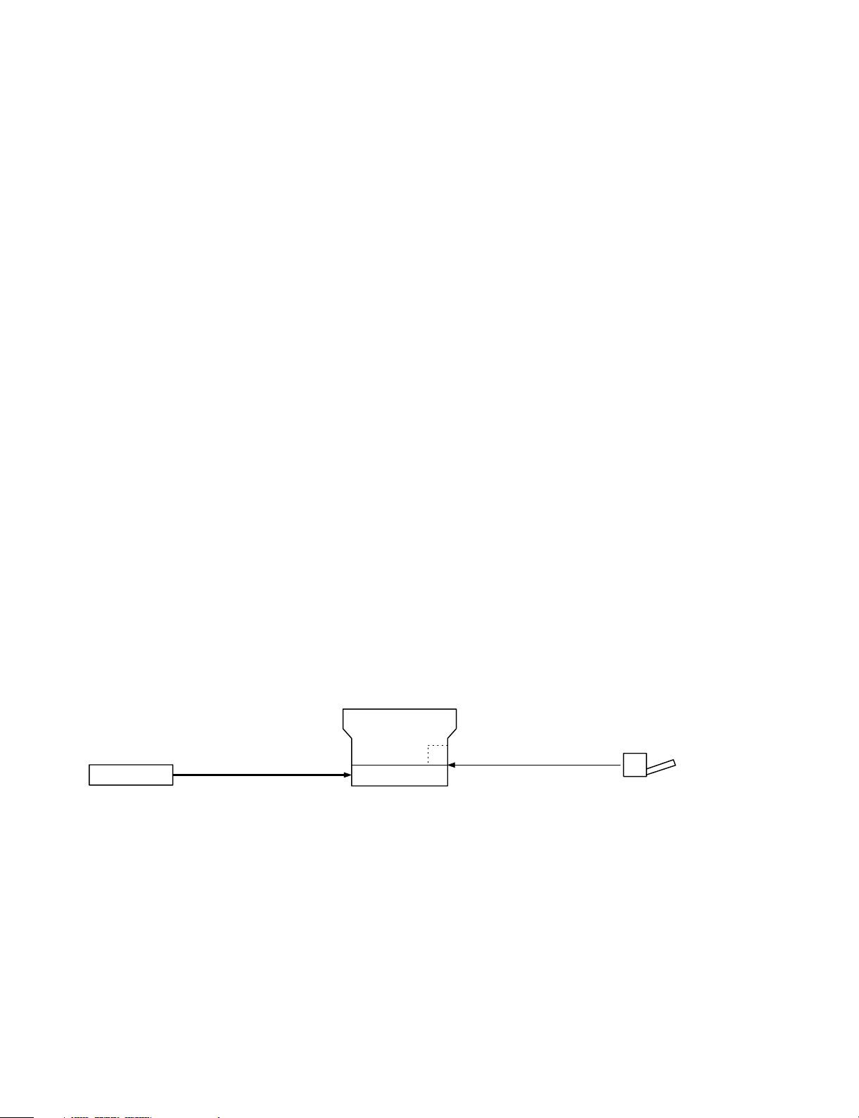
5. System outli ne
Zooming range
Z-800
250 sheets
(Option)
250-sheets paper tray
(SF-UB14)
* As the other options for all the models, the desk (SF-720D2) and the personal counter (SF-71A/71B) are available.
(1:1)
Single manual feed (Standard)
250-sheet tray
50-sheet mu l ti man ual feed uni t ( ZT - MF11)
(Option)
50
1 – 1
Page 5
[2] PRODUCT SPECIFICATIONS
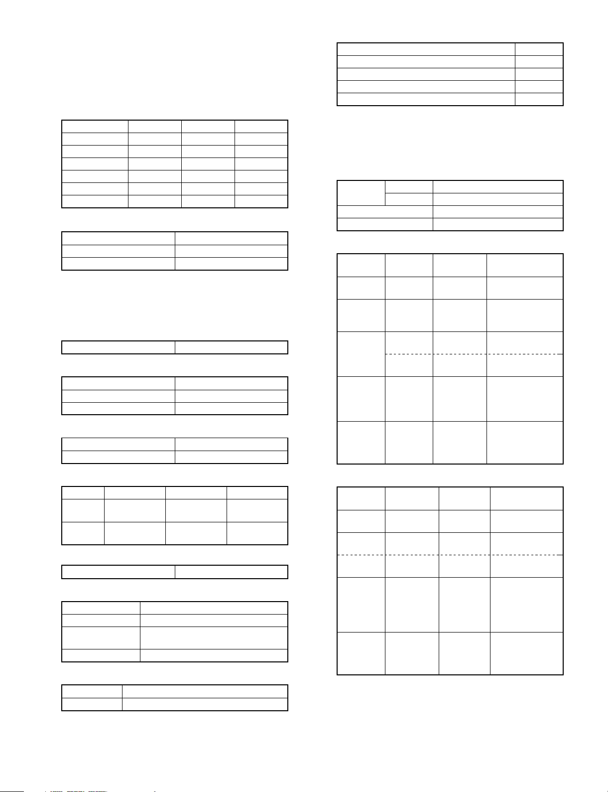
1. Basic specifica tio ns
(1) Type: Table top
(2) Copy speed
Paper size Normal Enlargement Reduction
B4 11 sheets/min — —
A4 (Landscape) 14 sheets/min — —
B5 (Landscape) 14 sheets/min — —
10″ × 14″ 11 sheets/min — —
Legal 11 sheets/min — —
Letter (Landscape) 14 sheets/min — —
(3) Warm-up time
Normal Max. 30 sec
Pre-heat Max. 10 sec
Auto power shut off Max. 30 sec
(4) First copy time: 5.9 sec (Fed from No. 1 cassette)
(5) Jam recovery time: 5 sec (Condition: Jam in a section except
for the fuser section, within 6.0 sec from
door open, standard condition.)
(6) Multi copy
Max. quantity of multi copy 99 sheets
(7) Document
Max. document size B4/10″/14″
Document reference position Left side
Detection No
(8) Exposure
Exposure mode Auto/Manual/Photo
Manual steps 9 steps
(13) Power consumption
Max. power consumption 1.4 kW
Average power consumption when operating 0.48 kW
Power consumption in standby 0.095 kW
Power consumption in pre-heating 0.056 kW
Power consumption in auto power shut off 0.026 kW
Note: Max. value when an option is installed.
2. Details of each section
(1) Paper feed section
Copy size
Paper feed system 1 cassette + manual paper feed
Paper feed capacity 250 × 1 + 1 or 50
• AB series
Paper feed
port
Tray B4 ∼ A5
Paper feed
unit
(OP)
Single
manual feed
Multi
manual feed
• Multi
paper feed
• Single
paper feed
AB series B4 ∼ A6
Inch series 10″ × 14″ ∼ 4″ × 6″
Paper feed
size
(Landscape)
B4 ∼ A5
(Landscape)
B4 ∼ A6
(Portrait)
A4 ∼ A5
(Portrait)
B4 ∼ A5
(Portrait)
B4 ∼ A6
(Portrait)
A4 ∼ A5
(Portrait)
Paper weight Special paper
56 ∼ 80g/m2Recycled paper
56 ∼ 80g/m2Recycled paper
52 ∼ 130g/m2Second original,
104 ∼ 130g/m2Postcard, recycled
52 ∼ 130g/m2Postcard, recycled
52 ∼ 130g/m
104 ∼|130g/m
OHP, label
paper
paper
2
Second original,
OHP, label, postcard,
2
recycled paper
(9) Void width
Normal Enlargement Reduction
Void area
Image
loss
(10) Paper exit
Paper exit tray capacity 100 sheets
(11) External demensions
W × D × H (mm) 500 × 480 × 295
Occupying width (mm)
(12) Power source
Power source 120V
Frequency 60Hz
Lead edge
3.0mm or less
Lead edge
3.0mm or less
Weight 26.2 Kg
Lead edge
3.0mm or less
Lead edge
2.5mm or less
Z-800
500 + 261 (Paper exit tray) +
205 (Option MB)
Lead edge
3.0mm or less
Lead edge
5.0mm or less
• Inch series
Paper feed
port
Tray 10″ × 14″ ∼
Single
manual feed
Multi
manual feed
(OP)
• Multi
paper feed
• Single
paper feed
Paper feed size Paper weight Special paper
invoice
10″ × 24″ ∼
4″ × 5″
Letter ∼
4″ × 6″
10″ × 14″ ∼
4″ × 6″
10″ × 14″ ∼
4″ × 6″
Letter ∼
4″ × 6″
15 ∼ 21 lbs Recycled paper
14 ∼ 34.5 lbs Second original,
28 ∼ 34.5 lbs Postcard, recycled
15 ∼ 21 lbs Recycled paper
14 ∼ 34.5 lbs
28 ∼ 34.5 lbs
OHP, label
paper
Second original,
OHP, label,
postcard, recycled
paper
2 – 1
Page 6
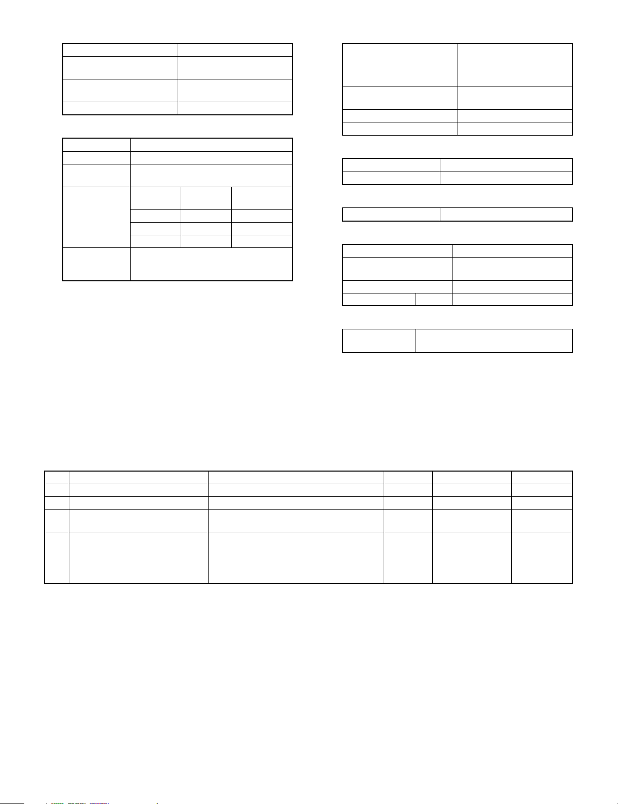
(2) Optical section
Light source Halogen lamp
Exposure system Slit exposure by moving the
light source
Magnification ratio changing
system
Lens Fixed focus lens
(3) Process section
Charging system (–) DC scorotron system
Transfer system (–) DC scorotron system
Separation
system
Copy mode
Main charger
grid voltage
Charge/Transfer
charger applied
voltage
Standard 8-02 –750V±10V
Photo 8-03 –459.9V±10V
Toner save 8-04 –634.4V±10V
By changing the lens
position and scan speed.
Discharge plate/separation pawl
Simulations
No.
–50.0µA ± 4µA
Grid voltage
(4) Developer section
Developing system Novel two-component
developing system
(Developer replacement not
required)
Toner density detection
system
Toner box capacity Developer 48g, toner 180g
Developing bias DC–200V±5V
Magnetic sensor system
• Developer
Material Iron powder carrier
Charging system Negatively charged by friction
• Toner
Charging system Positively charged by friction
(5) Fuser section
Fusing system Heat roller system
Upper heat roller surface
temperature
Standard 170°C
Heater lamp 120V Halogen lamp 1000 W × 1 pc.
(6) Drive section
Main motor
standard
Rating: DC32V, max. 1.32A, 1500 rpm
180°C
3-phase full wave drive, DC brushless
3. Supplies
No. Item Contents Life Model name Packing unit
1 OPC Drum Cartridge • OPC Drum Cartridge x 1 20K ZT-80DR 10
2 Black Toner • Black Toner Cartridge x 1 4K ZT-80TD1 10
3 Black Developer • Black Developer Cartridge x 10 SF-214MD1
(SF-214ND1 x 10)
4 Heat Roller Kit • Upper Heat Roller x 1 80K SF-214HR1 5
• Upper Separation Pawl x 3
• Lower Heat Roller x 1
• Lower Separation Pawl x 3
1
2 – 2
Page 7
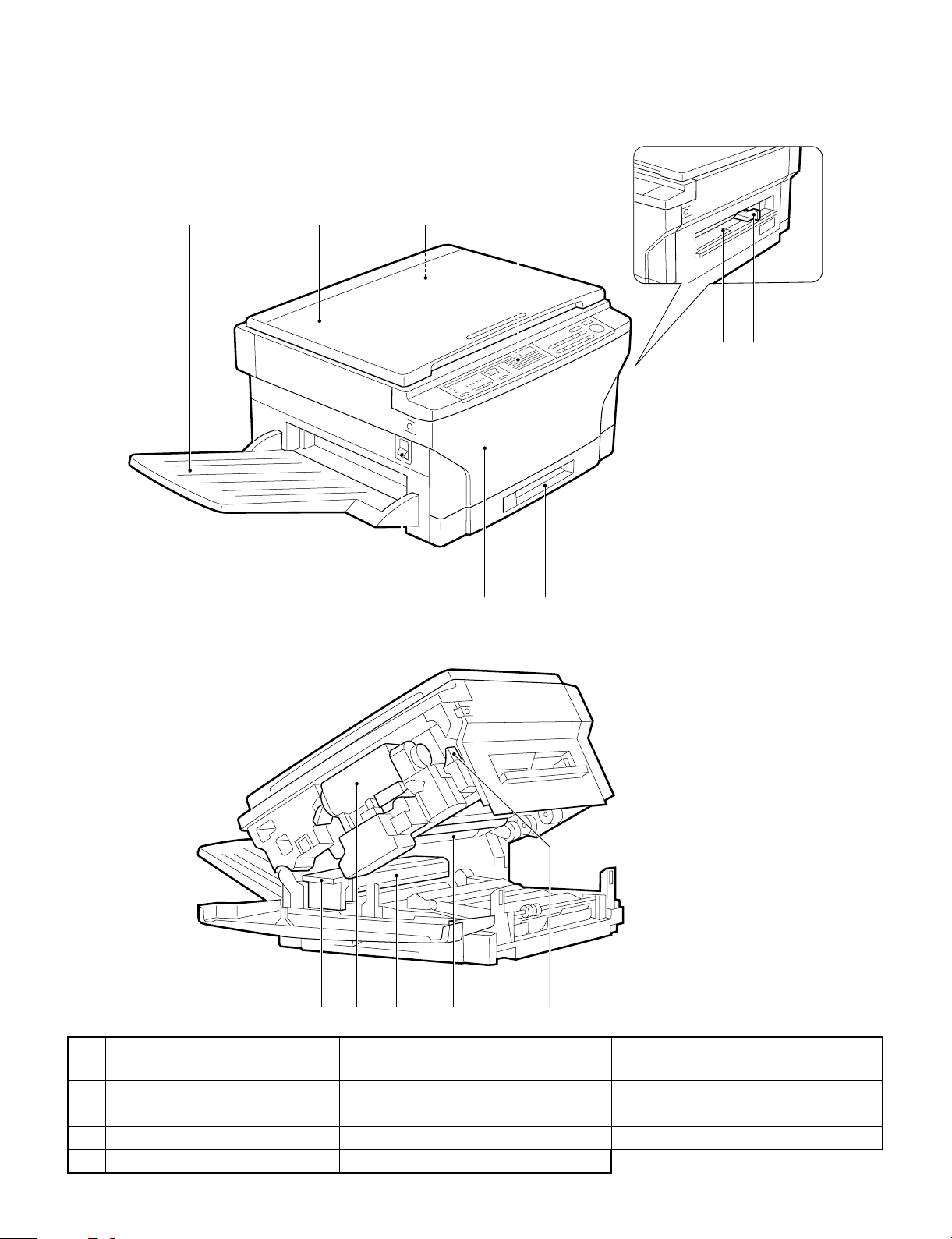
[3] EXTERNAL VIEW AND INTERNAL STRUCTURE
1. External view and intern al str uctu r e
2134
65
97 8
F G H I J
No. Name No. Name No. Name
Exit tray
1
Operation panel
4
Power switch
7
Fusing unit lever
F
Photoconductive drum
I
Document cover
2
Manual by-pass
5
Front cover
8
Toner cartridge
G
Release lever
J
Document glass
3
Manual by-pass guide
6
Paper tray
9
Fusing unit
H
3 – 1
Page 8
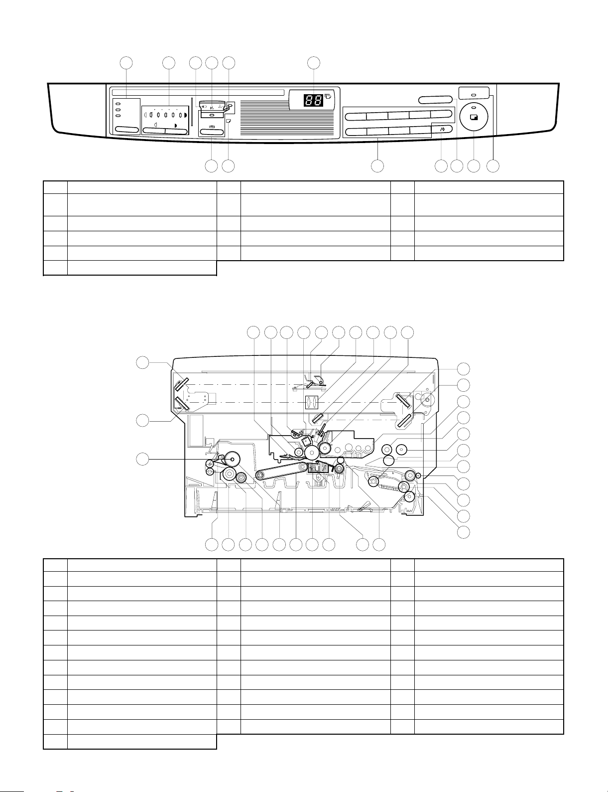
2. Operation panel
1 2 3 4 5 8
EXPOSURE TRAY SELECT
AUTO
MANUAL
PHOTO
No. Name No. Name No Name
Auto/manual/photo key and indicators
1
Misfeed indicator
4
Paper required indicator
7
Zero/read-out key
F
Power save indicator
I
21 345
4
3
2
1
9
8
7
6
6
7
Light and dark keys and exposure
2
indicators
Toner required indicator
5
Copy quantity display
8
Clear key
G
9 10 11 12 13
Drum replacement required indicator
3
Tray select key and indicators
6
10-key pad
9
Print button and ready indicator
H
POWER SAVE
C
5
0
3. Cross section
4
3
2
1
34
78
9
10 1165
12
13
14
15
16
17
18
19
20
21
22
23
2528 27 262930313233
24
No. Name No. Name No Name
No.3 mirror
1
Cleaner unit
4
No.1 mirror
7
No.6 mirror
F
No.4 mirror
I
Manual paper feed roller
L
Tray paper feed takeup roller
O
Tray paper feed roller
R
Resist roller
U
Suction belt
X
Lower heat roller
[
Heater lamp
^
No.2 mirror
2
Discharge lamp
5
Copy lamp
8
Blank lamp
G
No.5 mirror
J
Manual feed take-up roller
M
Tray transport follower roller
P
Tray paper feed reverse roller
S
Transfer charger
V
Upper heat roller
Y
Lower separation pawl
\
Drum separation pawl
3
Main charger unit
6
Lens unit
9
Developer magnet roller
H
Developer tank
K
Manual paper feed follower roller
N
Transport roller (Upper)
Q
Resist roller
T
Photoconductor drum
W
Lower cleaning roller
Z
Upper separation pawl
]
3 – 2
Page 9
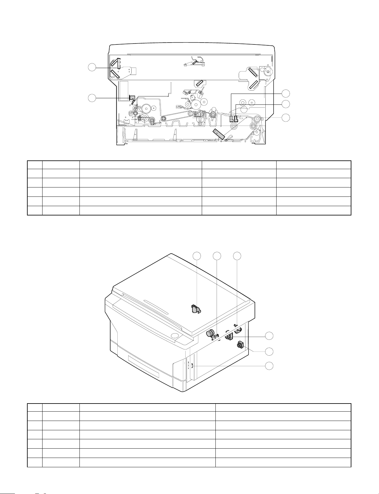
4. Switches, sensors, detectors
2
1
No. Abbreviation Function Type Operation
POD Paper out sensor Transmission photo sensor H when paper is sensed.
1
MHPS Mirror home position sensor Transmission photo sensor H at the home position.
2
PWD Paper size (large/small) sensor Transmission photo sensor L with the large size.
3
PPD Paper transport sensor Transmission photo sensor L when paper is sensed.
4
PED1 Tray paper empty sensor Transmission photo sensor H when paper is present.
5
4
3
5
5. Clutches, sol eno id s
1 2 6
3
5
4
No. Abbreviation Name Function and operation
PSPS Paper separation solenoid For paper separation solenoid drive
1
RRC Resist roller clutch For resist roller rotation
2
TRC Transport roller clutch For transport roller rotation
3
MPFS Manual paper feed solenoid For takeup roller pressing
4
CPFC1 Tray paper feed clutch For paper feed roller rotation
5
MPFC Multi paper feed clutch For multi paper feed roller rotation
6
3 – 3
Page 10
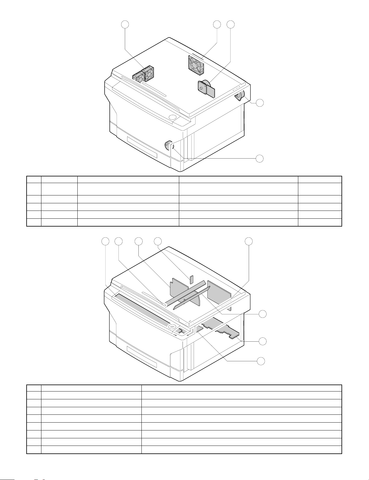
6. Motors
No. Abbreviation Name Function Type
VFM Paper exit fan motor
1
CFM Cooling fan motor For cooling the optical system DC brushless
2
MM Main motor For the main body drive and the option drive DC brushless
3
LM Lens motor For the optical lens drive DC stepping
4
TM Toner motor For toner supply DC synchronous
5
1
For ventilation of the fuser unit.
For cooling the machine and removing ozone.
2 3
4
5
DC brushless
7. PWBs
No. Name Description
AC circuit PWB AC power input
1
Discharge lamp PWB Discharge lamp drive
2
Main PWB Main body control
3
AE PWB Document density auto exposure detection
4
Blank lamp PWB Blank lamp control
5
Lower unit PWB Lower unit parts control
6
High voltage PWB Supply of the process high voltage and the developer bias voltage.
7
Operation PWB Operation input, display control
8
8 312 4
5
6
7
3 – 4
Page 11
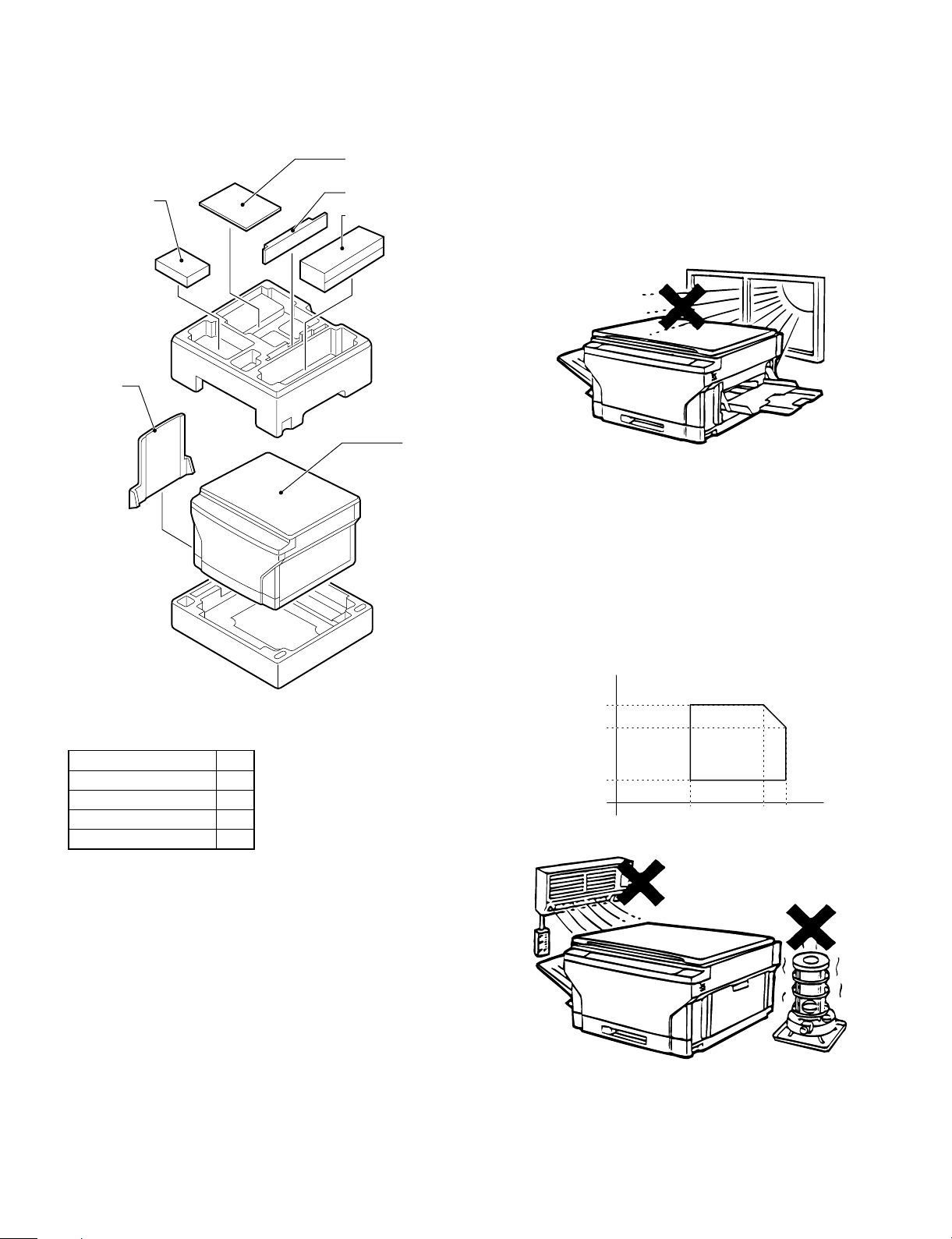
[4] UNP ACKING AND INSTALLATI ON
1. Packing drawi ng
2. Installat ion
Installation conditions
The following installing conditions must be satisfied to assure the
normal operations of the machine.
Toner Cartridge
Exit Tray
Operation Manual
Developer Cartridge
Drum Cartridge
Copier
(1) Environment
1 Keep the machine away from direct sunlight and avoid instal-
lation near a window or in a bright place.
(Draw the curtain and close the blind shutter completely.)
The plastic parts and the original cover may be deformed by direct
sunlight. Avoid installation near a window even with frosted glass.
2 Avoid installation in high temperature or high humitity en-
vironments. Also, avoid installation where temperature or
humidity may change quickly. (e.g., near an air conditioner).
Otherwise copy papers may be dampened and condensation may
be generated in the machine. This may result in paper jams or
poor copy quality.
(Ideal conditions): The best suitable conditions for machine
operation:
20°C ∼ 25°C: 65 ±5%RH
(Temperature/humidity range): 15°C ∼ 30°C, 20% ∼ 85%
65% for 35°C
Accessories
Drum cartridge 1
Developer cartridge 1
Toner cartridge 1
Exit tray 1
Operation manual 1
* Save the carton and packing materials. The carton and packing
can be re-used for transporting the machine, should it be necessary.
% RH
85
65
Humidity
20
15 30 35
˚C
4 – 1
Page 12
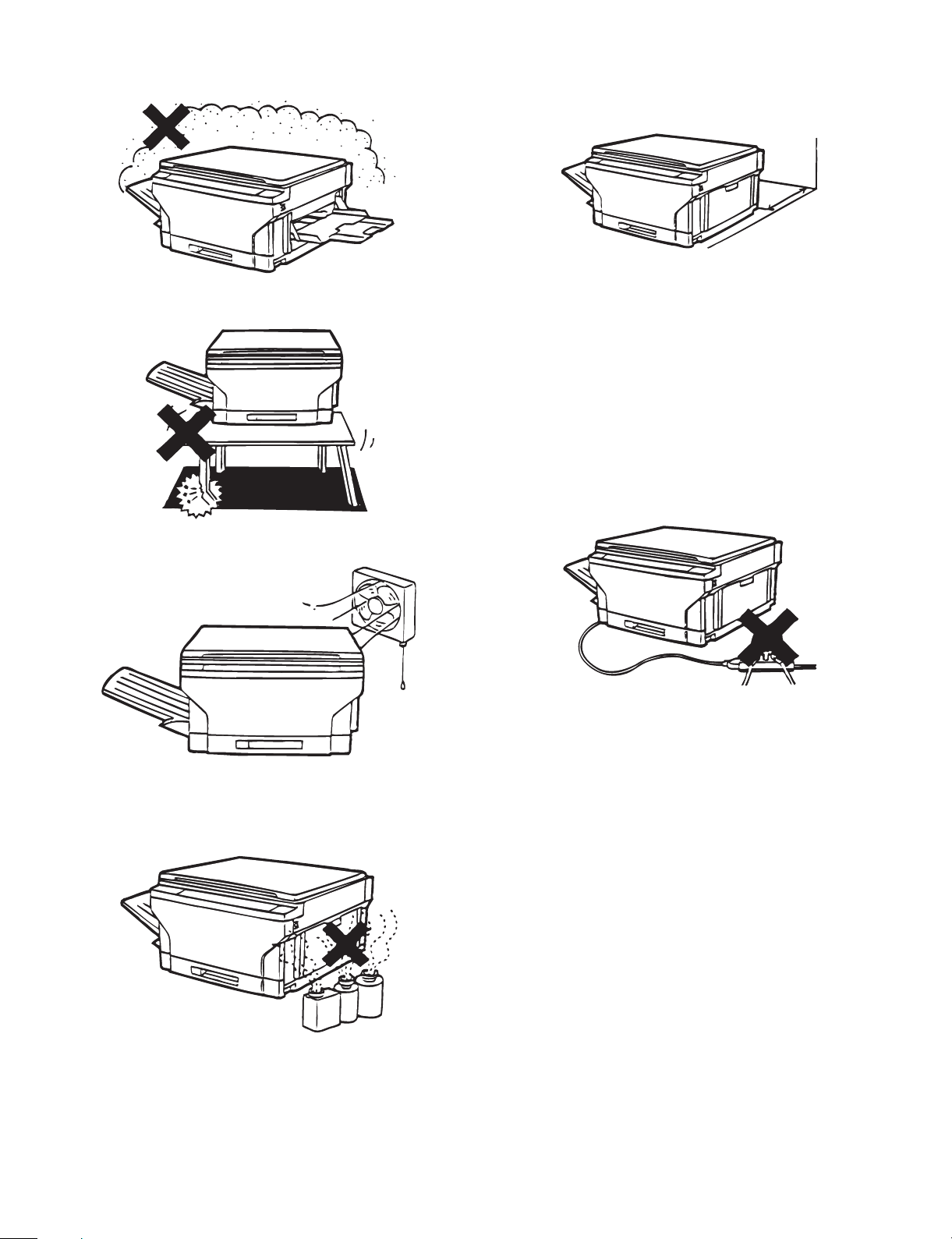
3 Avoid installation where there is a lot of dust or vibrations.
If dust enters the machine, it may degrade copy quality and cause
malfunctions.
(2) Space around the machine
Allow a space of about 15 cm (6 inches) between the rear side of the
machine and the wall for ventilation of the cooling fan. Also allow
sufficient space around the machine for operations.
15cm
4 Avoid installation on an unstable surface.
To assure the proper operations, install on a level surface.
5 Install in a well ventilated place.
6 Avoid installation where there is inflammable gases or am-
monium gases.
Installation near a diazonium copier may degrade copy quality and
cause malfunctions.
(3) Installing table
Use a level (UKOGM0054CSZZ) to install the machine horizontally.
(Note) If the machine is not installed horizontally, toner density con-
trol may not function properly. This may result in poor copy
quality.
(4) Power source
1 The power source should be the rated voltage ±10% with the
capacity corresponding to the max. power consumption.
2 Do not use an extension cord, or operate any other equipment
from the same wall outlet.
(5) Grounding
To avoid electrical hazard, use the properly grounded wall outlet only.
(Carrying the machine)
When carrying the machine, remove the copy tray and hold the dent
portions on the bottom.
7 Install near a power outlet.
4 – 2
Page 13
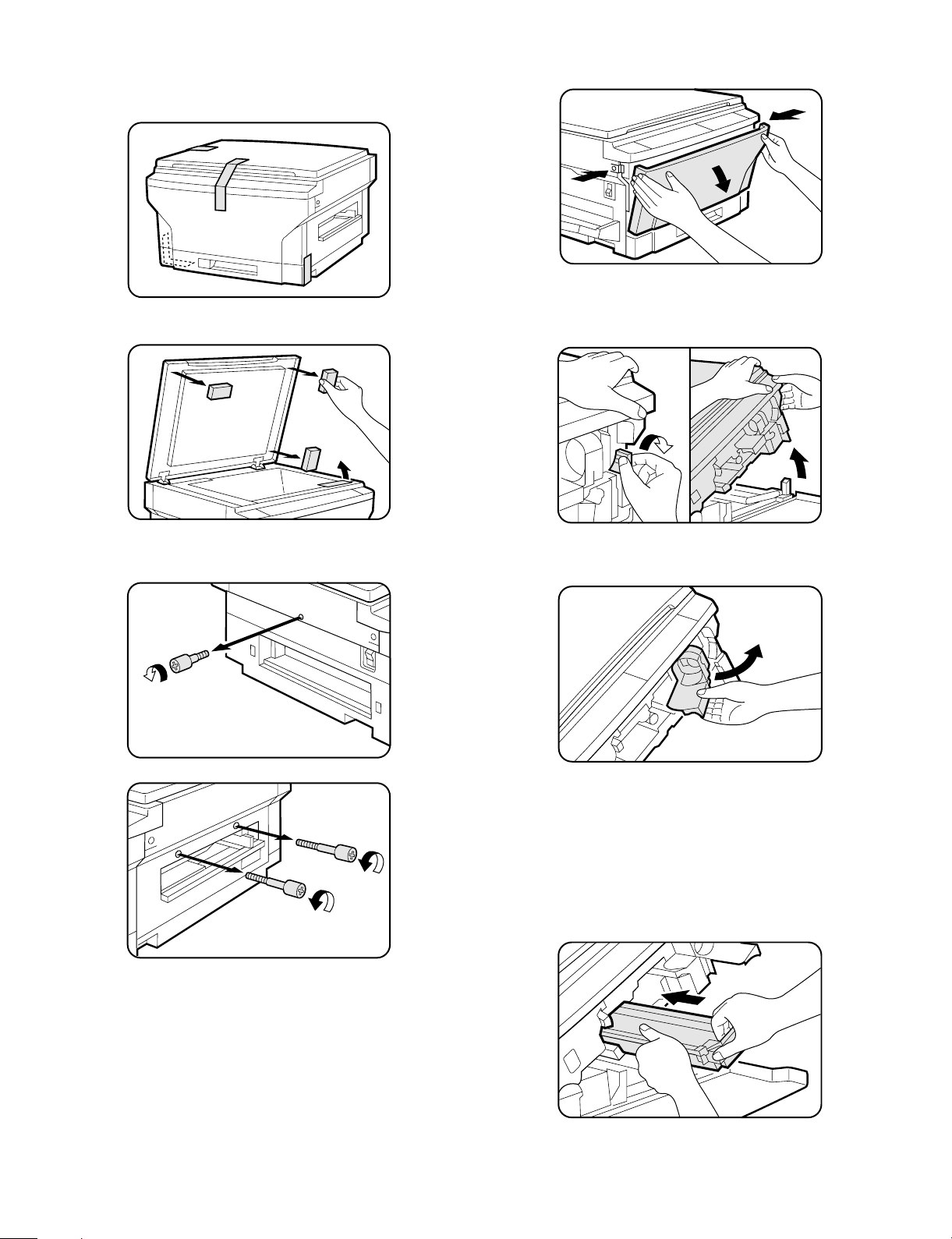
3. Installation procedure
1 Remove the copier from the bag and remove all pieces of
tape from the copier.
• Also remove the packing materials as shown.
3 Press the buttons on both sides to unlatch the front cover
and open it.
4 Press the release lever to open the upper half of the copier.
CAUTION: Be sure to open the upper unit slowly and gently, and
do not let go of it until it is fully open.
2 Remove the screw on the left side as shown, and remove the
two screws above the manual by-pass.
5 Grasp the handle of the toner cartridge holder, and swing the
holder out and to the right of the copier until it stops.
6 Remove the drum cartridge from its storage box.
• Remove the black wrapping paper from the drum cartridge.
• Save the box of the drum cartridge. The box should be used to
pack the drum cartridge if the copier must be transported for
servicing.
7 Slide the new drum cartridge in by holding the handle until
the cartridge locks in place.
• Be sure not to touch the surface of the drum.
4 – 3
Page 14
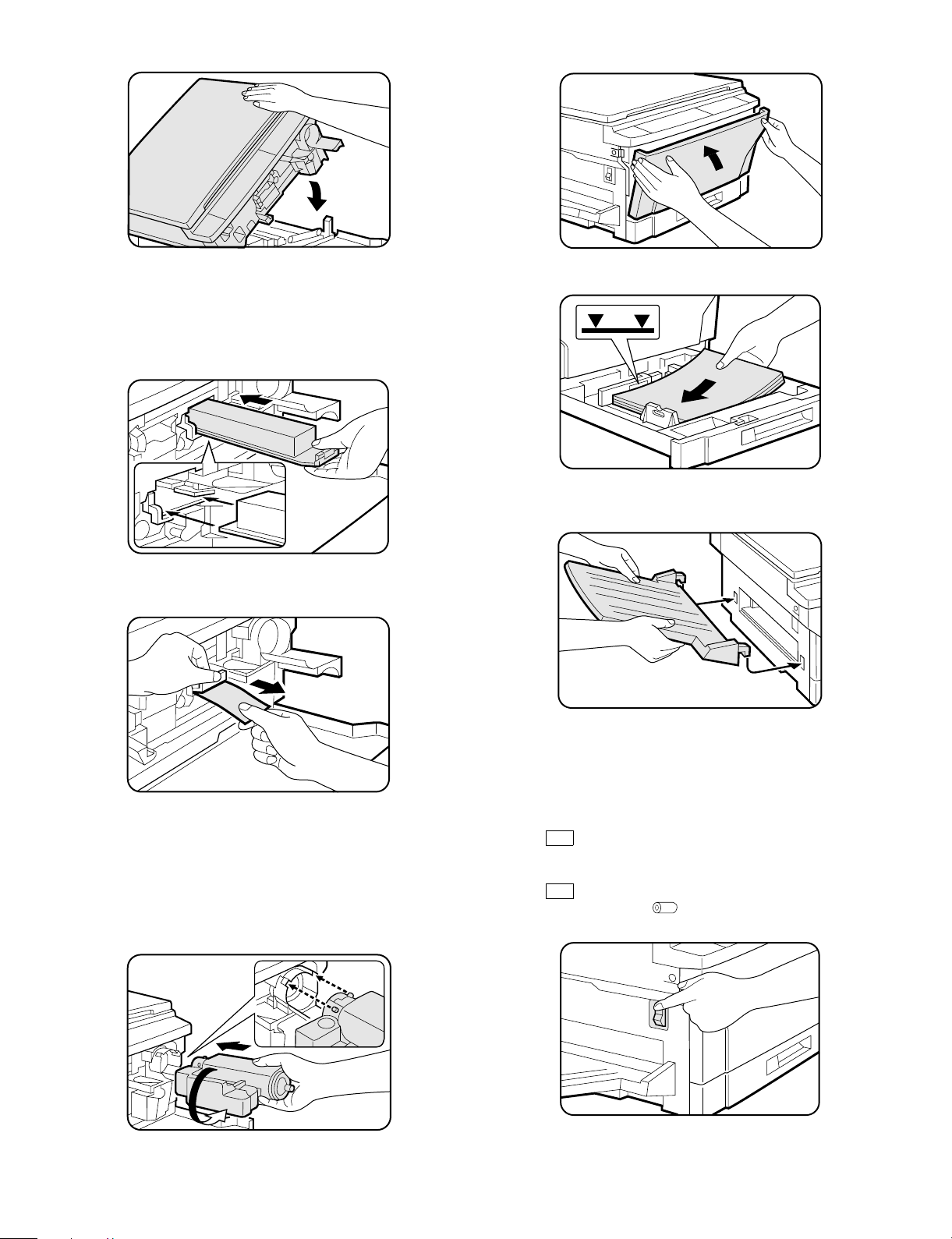
8 Push down on the upper half of the copier to close it.
H Close the front cover.
9 Insert the developer cartridge by positioning the lower left of
the cartridge along the rail and sliding it until it latches into
place.
CAUTION: When handling developer and toner cartridges for the
first time, do not remove sealing tape until the
cartridges are fully installed into the copier.
F Pull out the sealing tape and remove it from the developer
cartridge.
I Fan the copy paper and load it into the paper tray.
J Fit the exit tray onto the copier by inserting it at an upward
angle into the grooves on the left side of the copier.
G Shake the toner cartridge back and forth several times to
loosen the toner and then install it in the copier as shown.
Pull out the toner sealing tape. See steps 5 to 8 of ADDING
TONER on page 4-5.
• Save the box of the toner cartridge. The box should be used to
pack the toner cartridge if the copier must be transported for
servicing. The box should also be used for disposal of a used
toner cartridge.
➀
➁
K Plug the power cord into a grounded 120 volt outlet.
NOTE: Be sure the power cord is securely plugged in.
L Turn the power on.
• After about three minutes, the READY indicator will light up.
Copying is now possible.
• If
CH
blinks on the copy quantity display, the developer
cartridge is not installed properly. Check the developer
cartridge installation.
• If
CH
blinks on the copy quantity display and the drum replacement required ( ) indicator blinks, the drum cartridge
is not installed properly. Check the drum cartridge installation.
4 – 4
Page 15
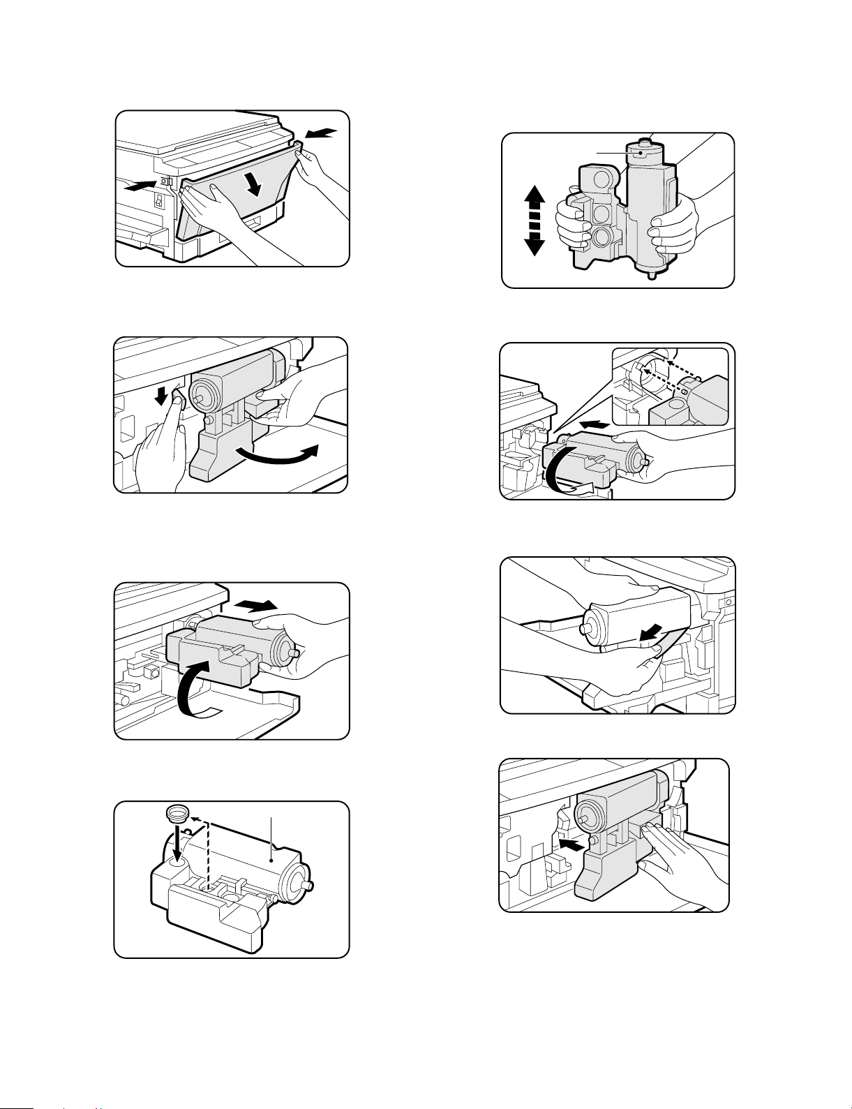
4. Addi ng to ne r
1 Press the buttons on both sides to unlatch the front cover and
open it.
2 Press down on the toner release lever while pulling the handle to
unlatch the toner cartridge. Grasp the handle and carefully swing
the cartridge out and to the right of the copier until it stops.
5 Take the replacement toner cartridge from its storage box and
shake the cartridge nine or ten times.
• Save the box for disposal of a toner cartridge.
CAUTION: Do not remove sealing tape until the toner cartridge is
fully installed into the copier.
Keep this side up.
6 Install the new toner cartridge by positioning the protrusions in the
slots and then rotating the cartridge counterclockwise 90°.
1
2
3 Gently rotate the cartridge clockwise 90° and then pull to remove
it.
CAUTION: Keep the old toner cartridge with the two holes up so
as not to spill used toner.
2
1
4 Attach the sealing cap onto the old toner cartridge.
• Use the storage box for disposal of the used toner cartridge.
1
2
7 While holding the toner cartridge, pull out the toner sealing tape
completely.
8 Swing the toner cartridge back in place and close the front cover.
Old toner cartridge
4 – 5
Page 16
5. Optional multi bypass feeder unit
Installation Manual
For use with compatible SHARP copiers.
See SHARP copier Installation Manual to determine suitability.
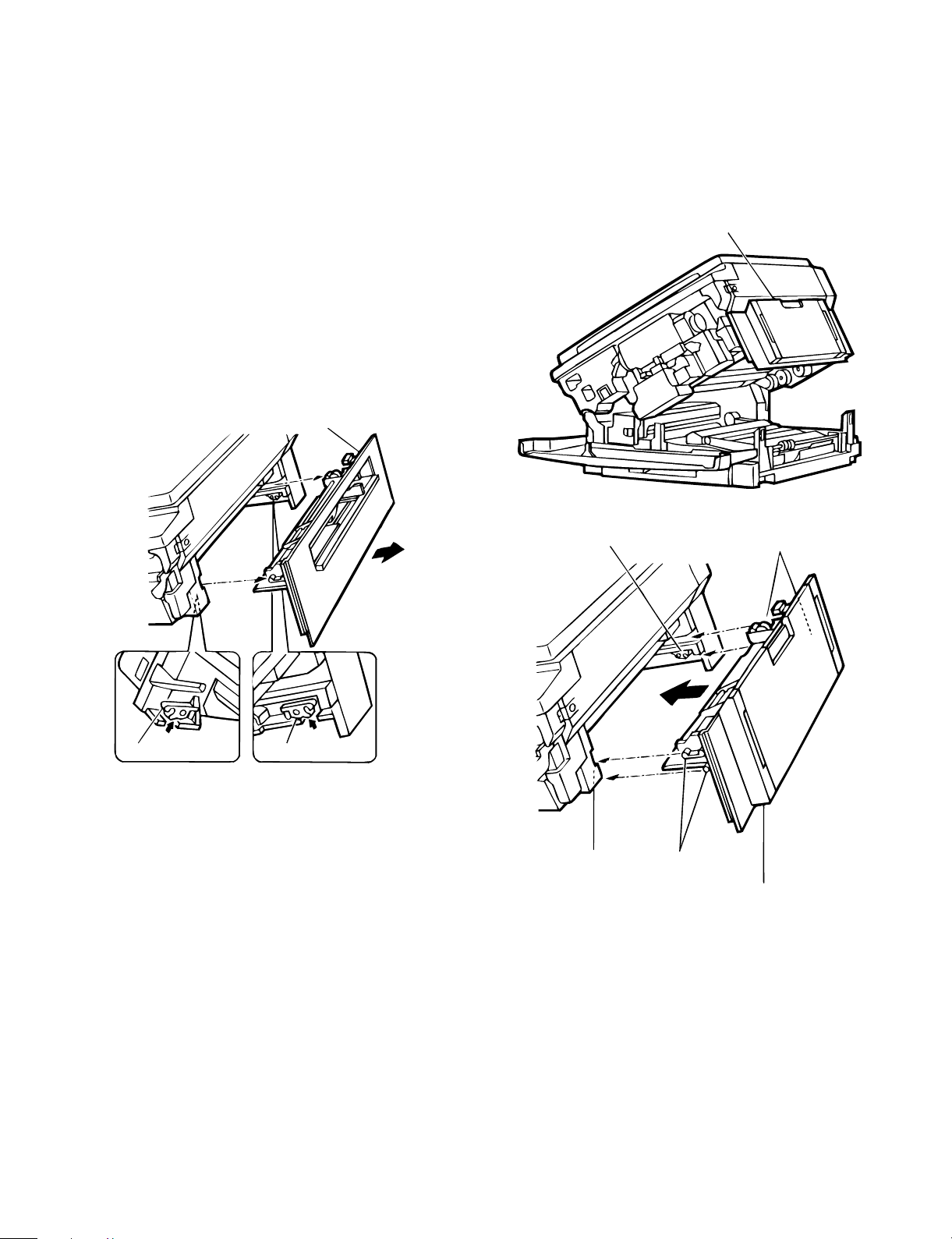
(1) Open the upper unit of the main copier unit.
1 Press the release buttons on the left and right sides of the main
copier unit’s front cover, then open the front cover.
2 Push the upper half release lever (green) to the right and down,
then gently open the upper unit.
(2) Release the lock for the manual bypass unit and
remove the manual bypass unit.
1 Release the manual bypass unit by pressing upward on the rock
claws (green; 2 locations) which lock it in place in the main copier
unit’s upper unit.
The manual bypass unit will come out toward you slighly.
2 Pull out upon the manual bypass unit to remove it from the main
copier unit.
Manual bypass unit
(3) Mount the multi bypass feeder unit onto the
main copier unit.
1 Slide the positioning pins which project from the multi bypass
feeder unit in to the grooves in the main copier unit, then push the
multi bypass feeder unit into place to in stall it.
At this time, to be sure that the multi bypass feeder unit is securely
installed, push down once more on the fourcorners of the unit. (If it
has not been securely installed, "CH" may appear in the COPIES
MADE display when the power is turned on.)
Multi bypass feeder unit
Rock claw (latch)
Rock claw (latch)
Rock claw (latch)
Rock claw
(latch)
Positioning pins
Positioning pins
Multi bypass
feeder unit
2 Close the upper unit of the main copier unit.
4 – 6
Page 17
[5] GENERAL DESCRIPTIONS OF
EACH SECTION
The general descriptions of the following sections are given:
1 Paper feed section
2 Separation, transport section
3 Fuser, paper exit section
4 Developer section
5 Optical system
6 Image forming section
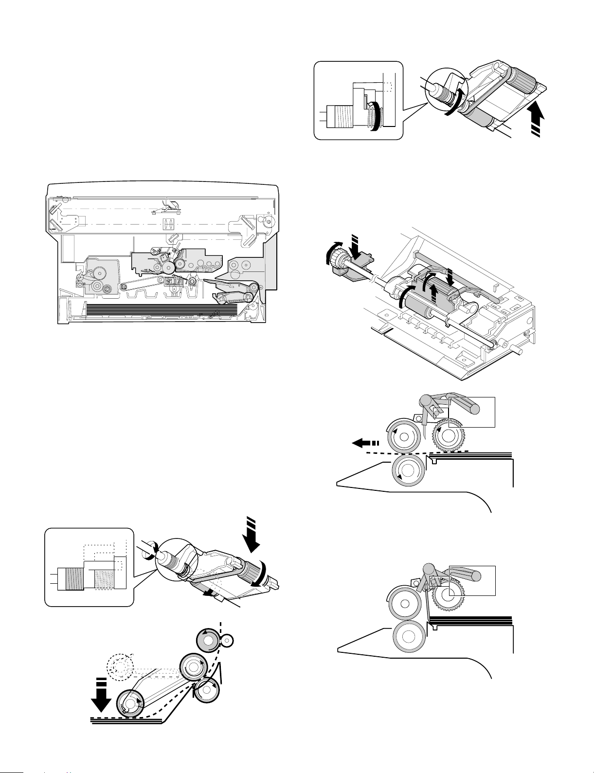
Internal structure
When the CPCF turns off, rotation is stopped, and the takeup roller is
pushed up by the roller release arm spring to the position.
(Manual paper feed operation) Multi
When the solenoid B (MPFS) turns on, the takeup roller falls and the
gate rises.
Almost simultaneously the solenoid A (MPFC) turns on and the
takeup roller and the paper feed roller turns to perform the paper feed
operation.
1. Paper feed secti on
The paper feed system is in two ways: the cassette feed and the
manual feed. The cassette is of the universal type and has the
capacity of 250 sheets. It is attached and detached at the front
cabinet, that is, the front loading system.
The manual paper feed is single. (The multi paper feed unit (ZTMF11) is an option.)
(Cassette paper feed operation)
The cassette paper feed clutch (CPFC) turns on, the paper feed roller
shaft, the paper feed roller, and the takeup roller rotate. At the same
time, the roller release arm is lowered by the limiter spring. As a
result, the takeup roller falls by its own weight to reach the paper
surface, performing the paper feed operation.
ON
When the PPD turns on, the MPFS turns off and the RRC turns on.
Almost simultaneously the MPFC turns off to return the roller and the
gate to the initial state.
OFF
5 – 1
Page 18
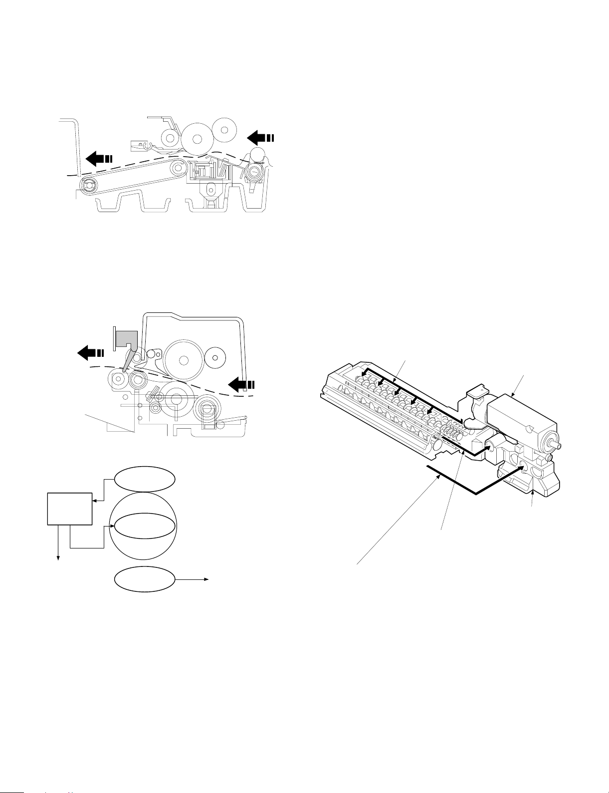
2. Separation, transport section
4. Developer section
After passing the resist roller section, the paper is transported to the
transfer section. After transfer, the paper is separated from the drum
by the separation electrode and the drum separation pawl, then
transported to the fuser section by the transport belt.
3. Fuser, paper exit section
The toner image transferred on the paper is fused by the heat and
pressure of the upper and the lower heat rollers. After fusing, discharge static electricity on the paper with the discharge brush. Then
the paper is discharged to the copy tray.
In the developer section, toner is attached to the electrostatic latent
image on the drum to change the latent image into a visible image.
Toner and carrier are charged by friction caused by the stirring roller
in the developer unit. Toner is charged in positive, and carrier is
charged in negative charge.
Since the latent image on the drum (area not exposed to light) is
negatively charged, it draws toner which is positively charged.
To prevent against excessive copying, a bias voltage of -200V is
applied to the MG roller.
This model employs the novel two-component developing system
(Developer replacement not required).
When, in the case of the conventional development method,
developer (mixture of carrier and toner) is deteriorated, developer
itself must be replaced or the whole developer unit must be replaced
as in the personal machines.
In the new development system, however, developer is supplied in a
certain cycle during development process (developer is mixed with
toner and supplied with toner when toner is supplied), and removed
(automatically by the overflow system when the rate of deteriorated
developer in the developer unit reaches a certain level), preventing
against deterioration in image quality and eliminating the need for
developer replacement in maintenance.
Therefore, "toner cartridge" supplied as a supply item is developer
(mixture of toner and carrier).
Deteriorated developer will overflow from the discharge port of the
developer unit automatically and collected by the waste toner collection container together with residual toner on the photoconductor
drum.
• Temperature control
Heat roller surface
temperature detection
The heat roller is heated by the
heater lamp.
(When the heat roller surface
temperature is 180 C˚ or lower,
the heater lamp is actuated)
Contact open (*)
Abnormal high
tem p erature
CPU
(Heater troub l e)
Self diag di spl ay
Thermistor
Heat r olle r
Heater lamp
Thermostat
• Abnormally high temperature (H3)
• Abnormally low temperature (H4)
• Thermistor disconnection (H2)
When the thermostat contact is open, it is required to press the
*
reset button in the upper side of the thermostat. (The contact is not
reset automatically.)
Flow of the new toner
Deteri orat e d deve lope r
(Automatical l y di scha rged to t he w aste t o ner
collection container)
Residual toner on the photoconductor drum
(Cleaned in section and sent to the waste toner collection container)
Toner box
(mix tu re o f tone r and carri e r)
Waste toner collection
container
5 – 2
Page 19
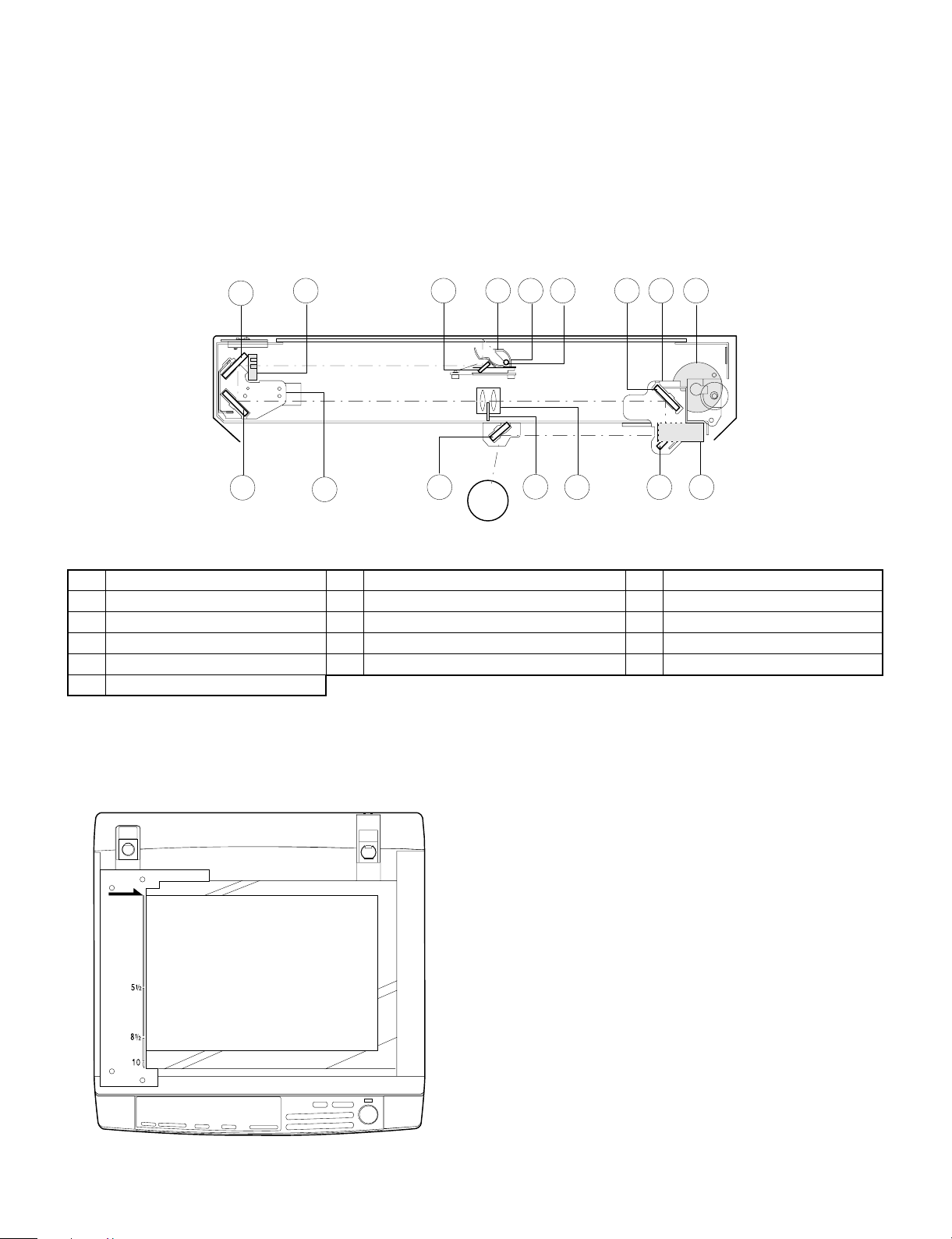
5. Optical system
5-1. General descriptions
• The optical system is composed of the fixed focus lens and six
mirrors.
Since the fixed focus lens is employed, No.4/No. 5 mirror base is
moved as well as the lens to change the distance between the
document and the drum (OID, Original Image Distance) for reduction and enlargement.
To move the lens, he stepping motor is driven by the signal from
the main control PWB (This model has no zooming function, and
its lens and No.4/No.5 mirror base are fixed.)
4
5
15
10
9
• Exposure is adjusted by changing the voltage of the copy lamp.
The copy lamp unit is provided with the AE sensor for detection of
the original density to adjust the light quantity of the copy lamp
according to the original density.
• For exposure, the slit exposure system is employed where the light
source is moved. (The original table is fixed.)
16
12
6
127
13113
8
14
1 Copy lamp 2 Reflector 3 No. 1 mirror
4 No. 2 mirror 5 No. 3 mirror 6 Lens
7 No. 4 mirror 8 No. 5 mirror 9 No. 6 mirror
F No. 2/No. 3 mirror base unit G Copy lamp unit H No. 4/No. 5 mirror base unit
I Mirror motor J Lens drive motor K Mirror home position sensor
L Auto exposure sensor
(1) Original table
The original table is fixed, and originals are set to the left frame side
as the reference.
(2) Copy lamp
100V s ystem (285W)
(3) Mirror
Six mirrors are used.
No. 1 mirror is provided in the copy lamp, No. 2/3 mirrors at the
No.2/3 mirror base, No. 4/5 mirrors at the No. 4/5 mirror base. The
No.2/3 mirror base is scanned during copying.
(4) Lens (Fixed focus lens)
• Construction (One group 3 lenses)
• Brightness (F8)
• Focus (175mm)
(5) Lens base
The lens is mounted to this lens base.
(6) No. 4/5 mirror base
The No. 4/5 mirror is installed to this base.
5 – 3
Page 20
(7) Mirror motor
The mirror motor is a stepping motor, and used to move the copy
lamp unit and the No. 2/3 mirror base in order to obtain the rpm
corresponding to each magnification ratio.
(8) Mirror home position sensor (MHPS)
Used to sense the home position of the copy lamp unit. This sensor is
a photo transmission type sensor.
(9) No. 2/3 mirror base
The No. 2/3 mirrors are attached to this base. The mirror base is
scanned by the mirror motor.
(Copy lamp control in each copy density)
80
70
CLV
(Copy lamp
application
voltage)
60
50
40
(V)
[MAX. 85V(170V)]
[MIN. 40V(80V)]
(10) Copy lamp unit
This is composed of No. 1 mirror, the thermal fuse, the copy lamp,
the exposure adjustment plate, and the reflector, and is scanned by
the mirror motor.
(11) Thermal fuse
The thermal fuse is closely attached to the reflector in order to
prevent against abnormal temperature rise in the optical system. In
case of abnormal temperature rise, the power for the copy lamp is
turned off.
100V system (117°C)
(12) Reflector
Light from the copy lamp is reflected onto the original.
(13) Exposure adjustment plates
Three exposure adjustment plates are attached to the copy lamp unit
to adjust the exposure balance in the front and the rear frame direction.
(14) Mirror base drive wire
This wire is used to transmit the drive power of the mirror motor to the
copy lamp unit and the No. 2/3 mirror base to scan the mirror base.
(15) AE sensor
The original density is detected with the intensity of the copy lamp
light reflected from the original. The measurement area is the mirror
base scan area of about 100mm at the center.
The element is a photo diode.
EX1
(Optical system dirt correction)
The Z-800 perform dirt correction by changing the copy lamp intensity
according to the dirt degree in the optical system (the copy lamp unit,
No. 1 mirror, No.2 mirror, No.3 mirror) to prevent against remarkable
degrading of copy quality.
The reference value is the AE sensor output value which is obtained
when the reference plate is exposed with the copy lamp voltage of
67.7V (135.4V) at power ON.
This value is checked with sim 44-02.
Reference plate (Glass holder)
CPU
Reference value
> Measured value
Correction data output
234
Table glass
Copy lamp light quantity "UP"
Automatic exposure
sensor
EX5
5-2. Basic operati on s
(Relationship among the original, the lens and the image in normal
copy ratio)
The distance between the surface of original on the table glass and
the lens is made equal to the distance between the lens and the
exposure surface of the photoconductor to make the original and the
image equal to each other.
5 – 4
Page 21
6. Copy process
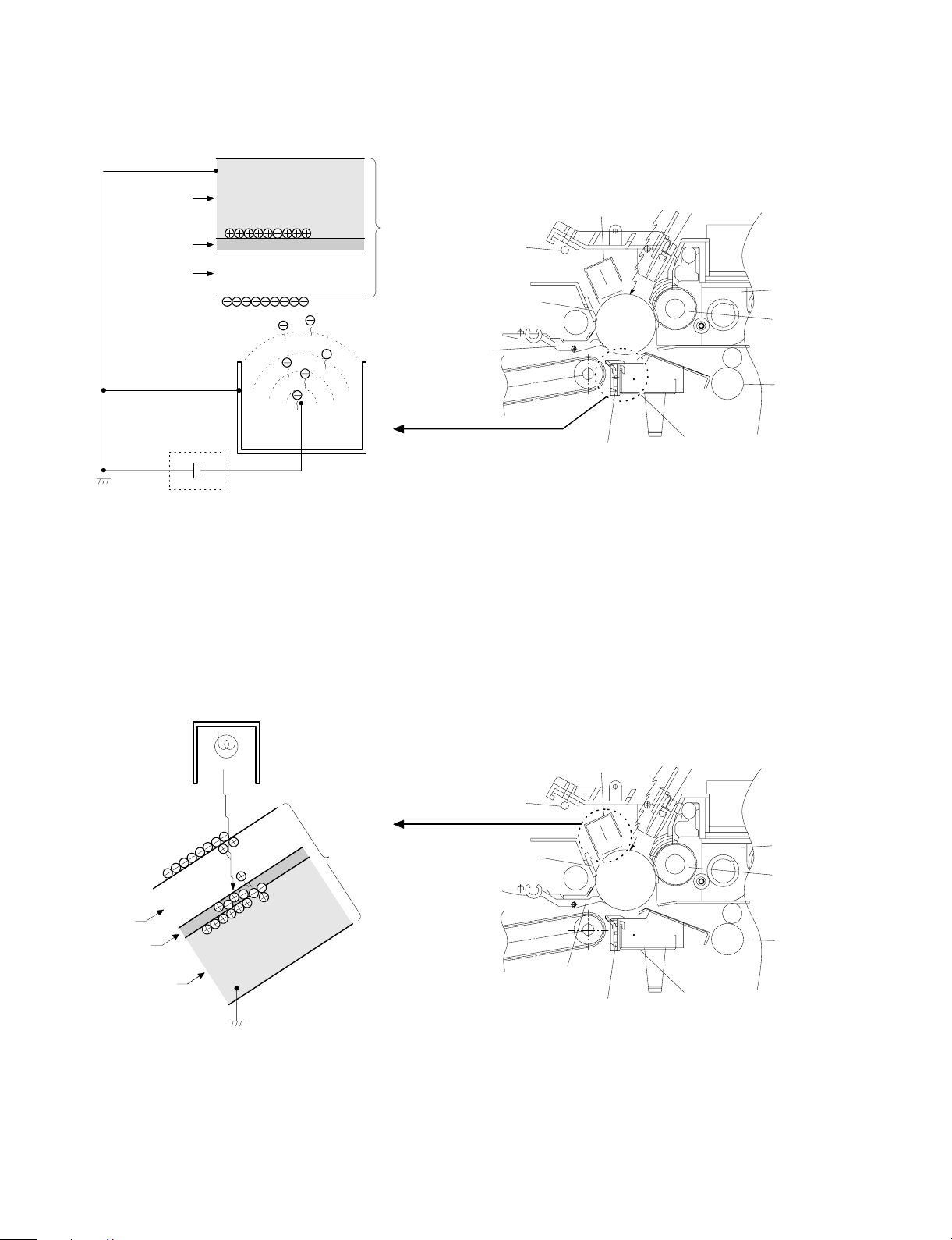
(1) Photoconductor
• This model uses OPC (organic photoconductor) as photoconduc-
tive material.
OPC layer CTL (Electric charge moving layer)
CGL (Electric charge generating layer)
Aluminum layer
(2) Process diagram
Original
Copy lampMirror lens
High voltage unit
Exposure
Transfer
Exposure
Development
Drum upper
ima ge/paper
synchronization
Resist roller
Discharge lamp
Cleaning bl ade
Waste toner collection
Paper exit
Main corona unit
Separ a tion
Fusing
Charging
Discharging
Cleaning
Separation
Blank lamp
Toner
Developer
High voltage unit
Paper feed roller
Transportroller
Manual paper feed
Pape r ca sse tte
Discharge lamp
Cleaning bl ade
Seper ati on pa w l
Heat r olle r
Heater lamp
Separation cor ona unit
High voltage unit
Main corona unit
Seperation corona unit
Transfer charger
High voltage unit
Blank lamp
Devel oper u nit
MG roller
Resist roller
Transfer corona unit
Image forming process
Paper transport path
5 – 5
Page 22
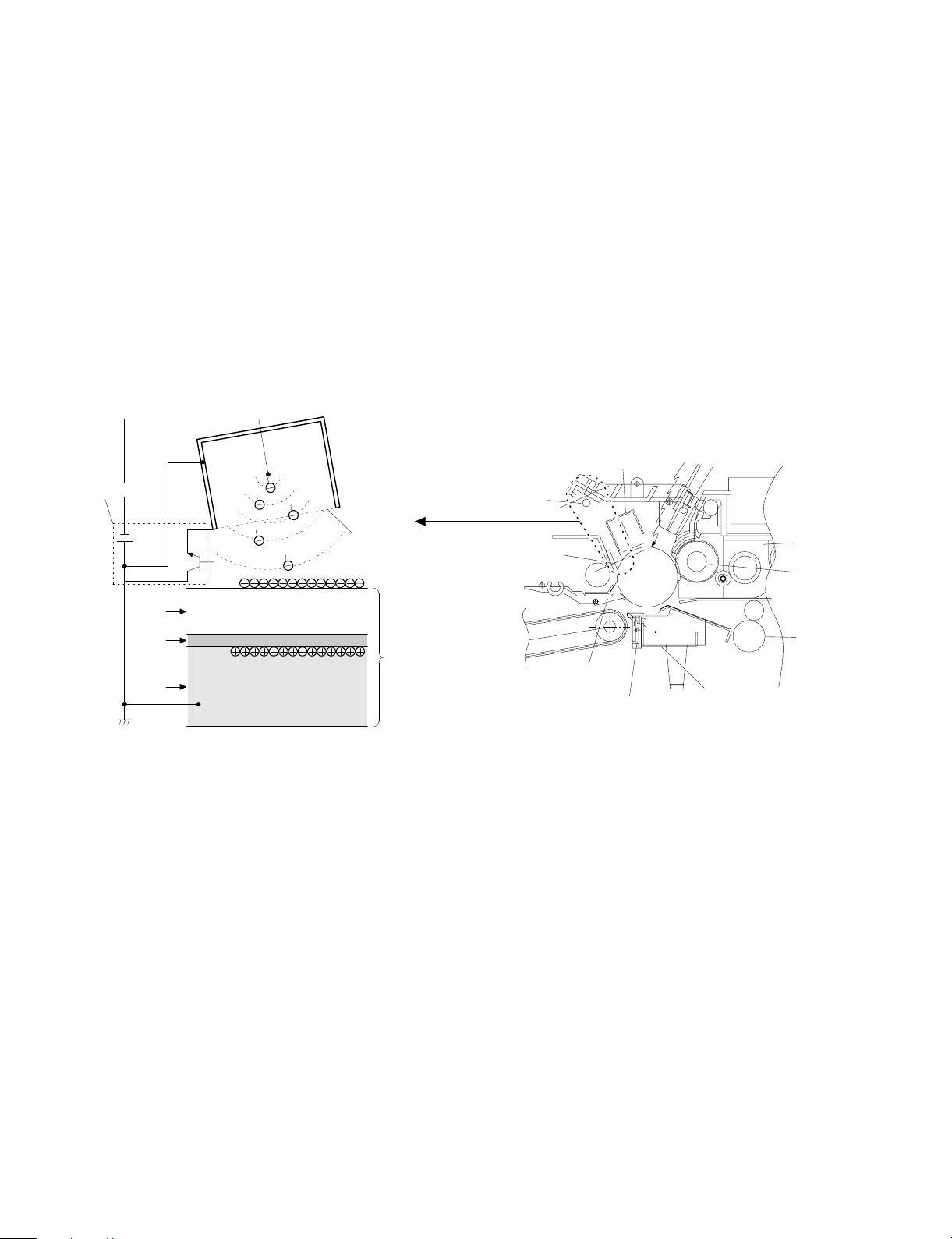
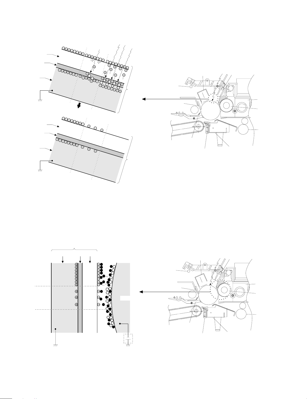
(3) Actual process
Step 1 (charging)
The OPC drum is negativelycharged by corona discharge of the
transfer charger . Positive charges are generated in the aluminum
layer.
Aluminum layer
OPC drum
CGL
CTL
Seperation pawl
Transfer corona unit
High voltage unit
Step 2 (Discharging)
When the OPC drum is exposed to the discharge lamp light, positive
and negative charges are generated in the OPC drum CGL. The
negative charges move to the positive charges generated in the
aluminum layer in step 1, and the positive charges move to the
negative charges on the OPC drum surface charged in step 1. The
positive charges and the negative charges are neutralized each other
in the aluminum layer and on the OPC drum surface. As a result, the
OPC dru m surface potential become s 20V ∼ 30V.
Discharge lamp
Cleaning blade
Main corona unit
Seperation corona unit
Blank lamp
Devel oper u nit
MG roller
Resist roller
Transfer corona unit
Discharge lamp
Light
OPC drum
CTL
CGL
Aluminum layer
By performing step 1 (Charging) and step 2 (Discharging), the
photoconductor itself is initialized to stabilize the drum surface potential.
Discharge lamp
Cleaning blade
Seper ati on pa w l
Main corona unit
Seperation corona unit
Blank lamp
Devel oper u nit
MG roller
Resist roller
Transfer corona unit
5 – 6
Page 23
Step 3 (Main Charging)
By negative discharging of the main charger, uniform negative charges are applied to the OPC drum surface.
The OPC drum surface potential is controlled by the screen grid
voltage to maintain the grid voltage at a constant level.
• When the drum surface potential is lower than the grid voltage,
electric charges generated by discharging of the charger go
through the screen grid to charge the drum surface potential until it
becomes equal to the grid voltage.
• When the drum surface potential virtually reaches the grid potential
level, electric charges generated by discharging of the charger
flows through the electrode of the screen grid to the high voltage
unit grid voltage output circuit, thus always maintaining the drum
surface potential at a level virtually equal to the grid voltage.
• The main corona unit employs the scorotron system to charge the
photoconductor surface to a certain level uniformly.
In addition, the conventional corona wire is replaced with the
corona charging mechanism by saw-teeth plate (stainless steel
plate of 0.1 mm thick). In corona discharge, oxygen molecules in
the air are ionized to generate ozone (O3). The mechanism restrict
the generation of ozone.
Main corona unit
Main corona unit
Blank lamp
High voltage unit
Screen grid
CTL
CGL
OPC drum
Aluminum
layer
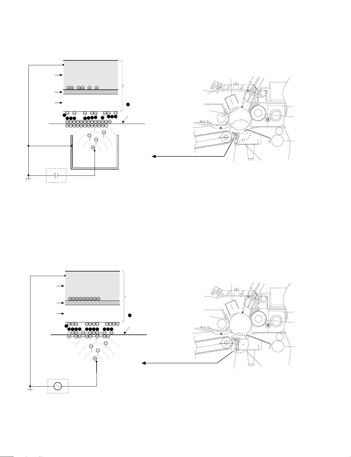
Step 4 (Exposure)
Light from the copy lamp is radiated on the document, and the optical
image of the document is reflected by the mirrors and projected
through the lens to the OPC drum.
The lighter portion of the document reflects more light (high intensity)
to the OPC drum, and the darker portion of the document reflect less
light (low intensity) to the OPC drum. Positive or negative charges are
generated in the CGL of the OPC drum where lights are radiated.
Negative charges generated in the CGL move towards the positive
charges in the aluminum layer generated in step 3. While the positive
charges in the CGL move towards the negative charges on the CPU
drum surface generated in step 3. Therefore, positive charges and
negative charges are neutralized in the aluminum layer and the OPC
drum surface at the light radiating position, decreasing the OPC drum
surface potential. The CGL electric charge generating amount increases in proportion to the document density, that is, reflected light
intensity (the OPC drum surface intensity). Therefore, electric charges are generated less in the CGL layer corresponding to the lighter
density of document (higher intensity of the OPC drum surface), and
a greater quantity of the negative charges on the OPC drum surface
is neutralized, decreasing the OPC drum surface potential more.
Discharge lamp
Cleaning blade
Seperation pawl
Seperation corona unit
On the contrary, electric charges are generated more in the CGL
layer corresponding to the darker density of document (lower intensity
of the OPC drum surface), and less quantity of the negative charges
on the CPU drum surface is neutralized, decreasing the OPC drum
surface less. Therefore, the OPC drum surface potential corresponding to the lighter portion of the document is lower, and that corresponding to the darker portion of the document is higher. Latent
static-electricity images are formed in the above manner.
Transfer corona unit
Developer unit
MG roller
Resist roller
5 – 7
Page 24
CTL
CGL
Low intensity in
the area corresponding to the
darker density
portion of the
document
Medium intensity
in the area corresponding to the
medium density
portion of the
document
HIgh intensity in
the area corresponding to the
lighter density of
the document
Aluminum
layer
OPC drum
Surface potential
(High)
CTL
CGL
Surface
potential
(Medium)
Surface
potential
(Low)
Aluminum
layer
OPC drum
Step 5 (Development)
Toner is attached to the latent static-electricity images on the drum
surface to change them to visible images. The two-component magnetic brush development system charges toner positively by friction
with carriers, and toner is attached to negative charges on the drum
surface. The potential in the darker document projecting area (low
intensity) is high (much negative charges) and attracts more toner.
The potential in the lighter document projecting portion (high intensity) is low (less negative charges), and attracts less toner.
Discharge lamp
Cleaning blade
Seperation pawl
Main corona unit
Seperation corona unit
Blank lamp
Developer unit
MG roller
Resist roller
Transfer corona unit
OPC drum
CGL
Aluminum layer
Higher surface
potential
(Much negative
(charges)
Medium surface
potential
(Less negative
(charges)
Lower surface
potential
(No negative
(charges)
CTL
MG roller
-200V
High voltage unit
bias voltage
At that time, a bias of –200V is applied to the MG roller (magnet
roller), which is provided for preventing toner from being attracted by
the residual voltage (about –80V to –100V) in the lighter portion after
exposure.
Discharge lamp
Cleaning blade
Seperation pawl
5 – 8
Main corona unit
Seperation corona unit
Blank lamp
Developer unit
MG roller
Resist roller
Transfer corona unit
Page 25
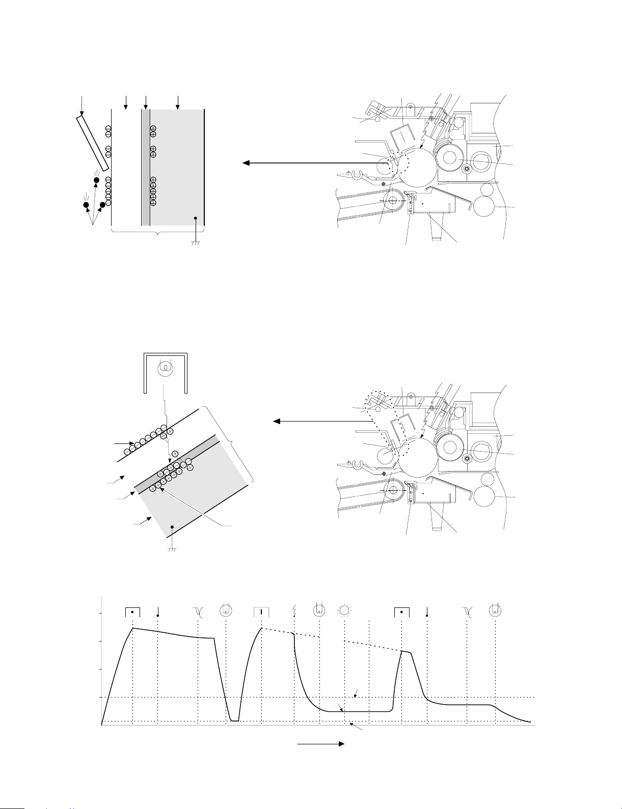
Step 6 (Transfer)
g
The transfer paper is charged higher than the OPC drum surface
potential by strong negative discharge of the transfer charger, making
the binding force between the transfer paper and toner stronger than
that between the drum and toner, attracting toner to the transfer
paper.
Aluminum
layer
OPC drum
CGL
CTL
Toner
Transfer paper
Seperation pawl
Transfer corona unit
h voltage unit
Hi
Step 7 (Separation)
After transfer, the copy paper and the drum are negatively charged.
Since, however, the negative potential of the copy paper is higher
than that of the drum, a attraction force is applied between the drum
and the copy paper. To avoid this, AC corona is applied to the copy
paper by the separation charger to decrease the copy paper potential
to the same level as the drum surface potential. The attraction between the copy paper and the drum is weakened by this, allowing
separation of the copy paper by its own extending force. If the copy
paper is not separated by the separation charger, it is separated by
the separation pawl mechanically.
Discharge lamp
Cleaning blade
Main corona unit
Seperation corona unit
Blank lamp
Developer unit
MG roller
Resist roller
Transfer corona unit
Aluminum
layer
CGL
CTL
High voltage unit
Seperation corona unit
OPC drum
Toner
Transfer paper
Discharge lamp
Cleaning blade
Seperation pawl
5 – 9
Main corona unit
Seperation corona unit
Blank lamp
Developer unit
MG roller
Resist roller
Transfer corona unit
Page 26
Step 8 (Cleaning)
Residual toner on the drum is removed by the cleaning blade. The
removed toner is sent to the waste toner container by the waste toner
transport screw.
Blade Aluminum layer
CTL
CGL
Residual toner
OPC drum
Step 9 (Discharging)
When the OPC drum is exposed to the discharge lamp light, positive
and negative charges are generated in the OPC drum CGL. The
negative charges generated in the CGL move towards the residual
positive charges in the aluminum layer, while the positive charges in
the CGL move towards the residual negative charges on the OPC
Discharge lamp
Discharge lamp
Cleaning blade
drum surface. Therefore, the positive and the negative charges are
neutralized in the aluminum layer and on the OPC drum surface,
removing the residual charges on the OPC drum surface. As a result,
the OPC drum surface potential becomes 20V ∼ 30V.
Main corona unit
Seperation pawl
Seperation corona unit
Main corona unit
Blank lamp
Developer unit
MG roller
Resist roller
Transfer corona unit
Blank lamp
Residual charge
OPC drum
CTL
CGL
Aluminum layer
Residual cha rge
(4) Transit of photoconductor drum surface potential
-800V
-600V
-400V
-200V
Separate
(OFF)
Clean
DLTransfer
Charge
Exposure
Discharge lamp
Cleaning blade
Seperation pawl
BL
Develop
Dark area
Light area
Seperation corona unit
Transfer
Developing
bias voltage
Transfer corona unit
Separate Clean
Developer unit
MG roller
Resist roller
DL
T (Time)
5 – 10
Residual potential
Page 27
(5) Process correction system
1) Outline of the correction system
This model is provided with the correction system for the optical unit
and the photoconductor drum unit. The combination of the two correction systems provides stable clear copy.
These functions are to maintain the copy quality for a long time and to
correct the characteristics of the parts, and are controlled by the
software and invisible from the outside.
2) Correction operation
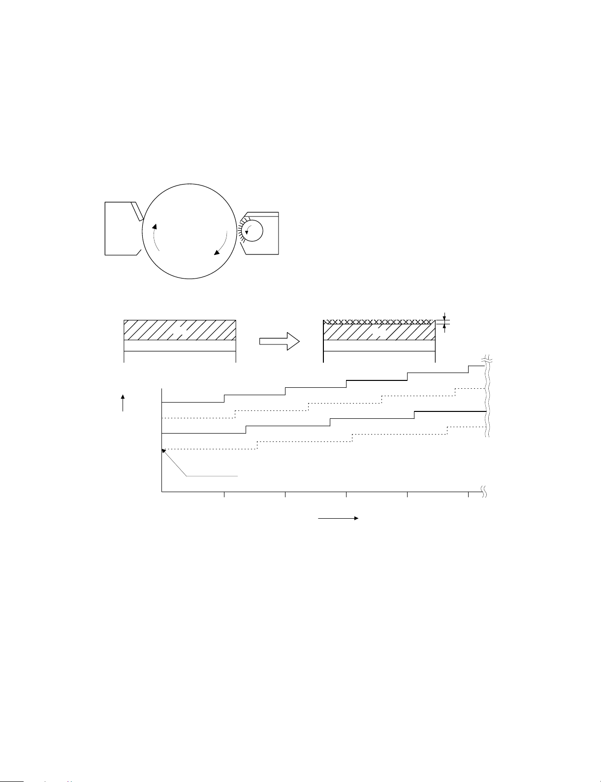
1. Photoconductor drum unit correction (Photoconductor
drum sensitivity correction)
Cleaner
Fig. 2
VCL
Correction level
(CL voltage)
Fig. 3
Change the tickness of the carrier transport layer (CTL).
Develop
OPC drum
By the developper.
By the cleaner blade.
Fig. 1
(NEW)
CTL
CGL
(USED)
Wear down
CTL
CGL
Manual mode exposure 1
Photo m od e exp o s u r e 1
Manual mode exposure 5
Photo m od e exp o s u r e 5
Correction level is initialized by Simulation 46 or
by replacing the photoconductor drum.
0 100 150 200 250
50
Drum r o tating time
min
The photoconductor drum is subject to mechanical stress by the
cleaning blade, resulting in wear in the OPC layer. In addition to that,
the photoconductor drum receives optical stress from the copy lamp.
These stresses reduce the photo sensitivity of the photoconductor
drum, producing unnecessary dirt copy. This trouble is removed by
adjusting the copy lamp voltage. For this model, however, to reduce
the number of service calls, the copy lamp voltage is automatically
dropped according to the reduction in the photo sensitivity of the
photoconductor drum to correct it.
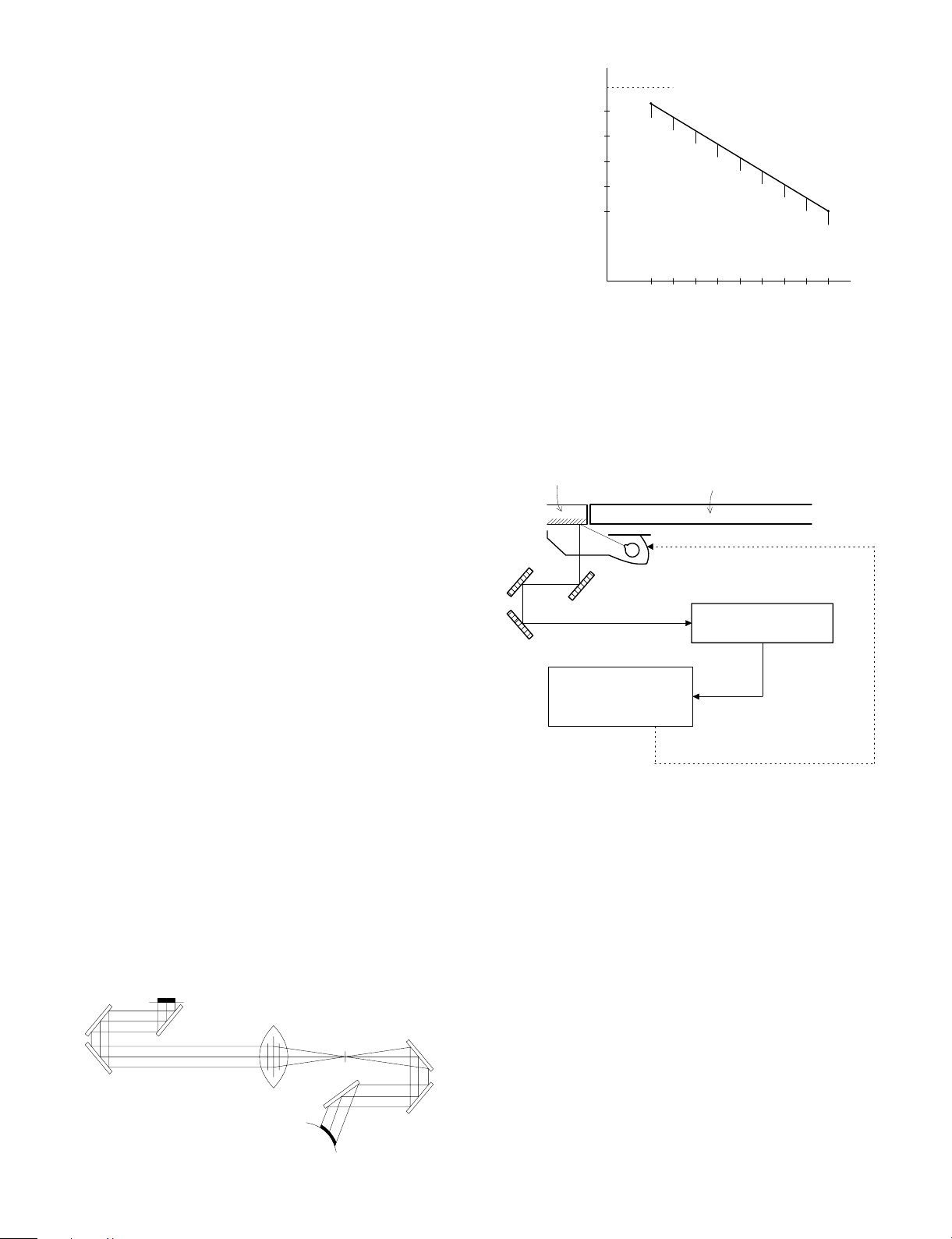
The drum rotating time from installation of a new photoconductor
drum is counted by the timer and the copy lamp voltage is corrected
in every mode. (Refer to Fig. 3.)
The correction is performed within the range of the max. supply voltage of the copy lamp. (The rotating time of the photoconductor drum
can be checked with Simulation 44-4.)
* The correction level is initialized by Simulation 46 or by replacing
the photoconductor drum.
5 – 11
Page 28
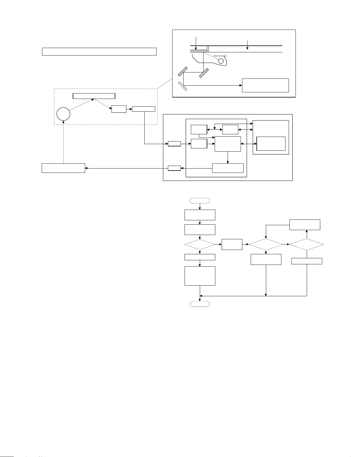
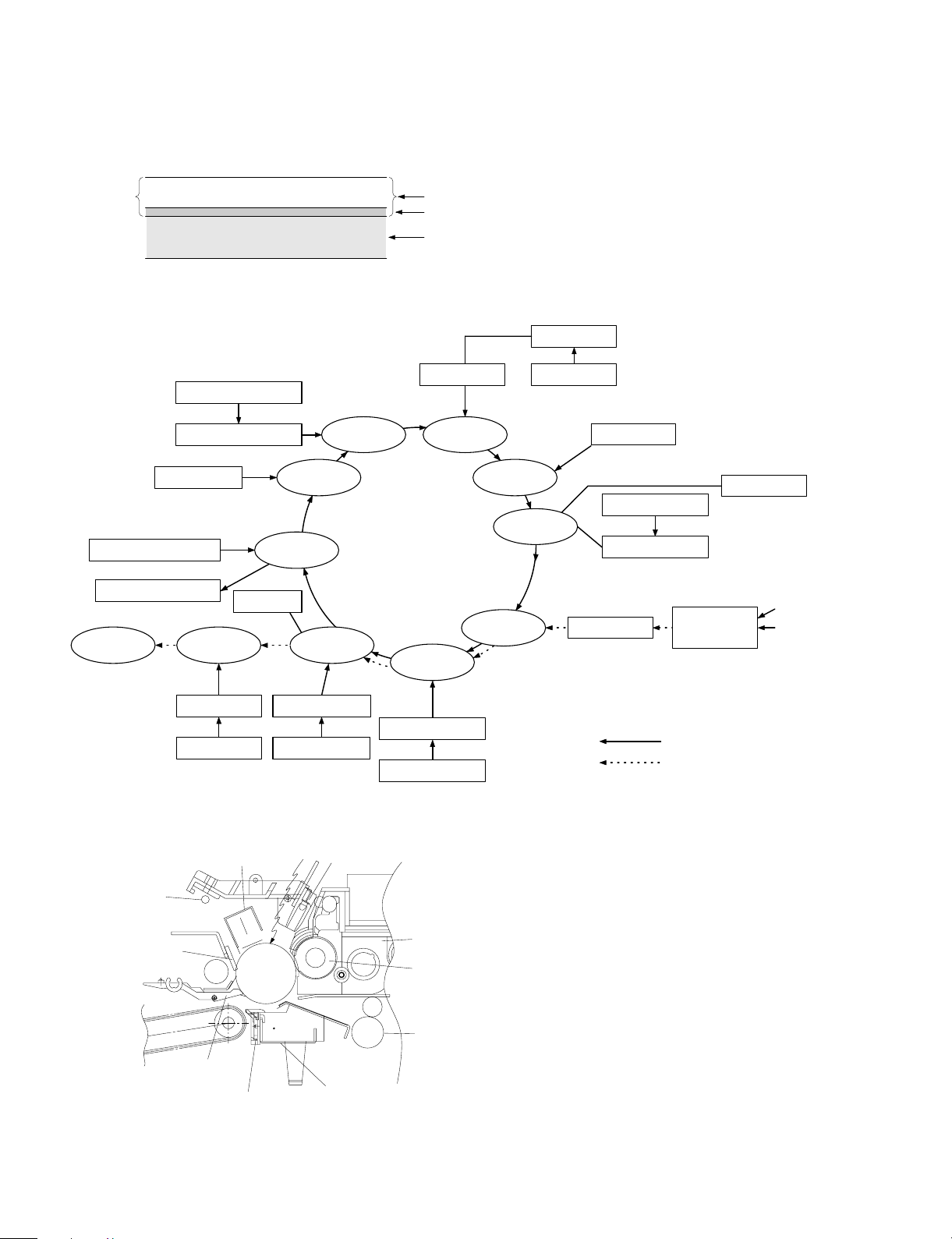
2. Optical unit correction (Dirt correction)
Diagram of correction system in the optical section
Referance refrection p late
Copy
lamp
AC power supply unit
(Copy lamp control circuit)
Mirror
AE SENSOR
The purpose of this correction is to maintain the copy density even
though the optical unit is contaminated and to reduce troublesome
cleaning of the optical unit.
When the lamp, the mirror, and the reflector are dirtied with dusts and
toner, the light quantity radiated to the photoconductor drum is
reduced, increasing the copy density and producing unnecessary
background copy.
The above trouble is removed by changing the copy lamp voltage to
adjust the copy density. It, however, requires serviceman’s operation.
In this model, the AE sensor senses dirt on the copy lamp, the mirror,
and the reflector, and the copy lamp light quantity is changed according to the dirt level to reduce the change in the copy density due to
the optical unit dirt.
When the optical parts are dirtied, the reflection rate is reduced to
reduce the quantity of light which is passed to the optical dirt sensor.
In this manner the dirt level is sensed.
[Initial setting]
After execution of Simulation 46, the scanner unit stops at the position of the standard reflection plate on the back of the document
stopper to light the copy lamp at a certain level, and the AE sensor
output level at that time is recorded as the reference value. (The
reference value can be checked with Simulation 44-2.)
[Correction timing]
The correction is performed after the copy cycle after turning on the
power, or after the specified time of rotation of the photoconductor
drum.
[Correction operation]
The same operation as the initializing is performed to change the
copy lamp voltage until the AE sensor output level reaches the same
level as the reference value, performing the correction.
The copy lamp voltage is revised to a new value at every correction,
and the new value will be used in the next correction.
(The correction voltage value can be checked with Simulation 44-3.)
AMP
Driver
Referance refrection plate
MAIN CONTROL PWB
Counter
watcher
A/D
converte r
CPU
Arithmetic unit
Copy lamp control
clock generator
START
Scanner unit
initial operation
The sc an ner unit s tops
at the standard reflection plate position.
YES
Correction
mode ?
NO
Copy lamp ON
Optical dirt sensor
standard level
(DSENS) memory
End
Total
counter
Copy lamp ON
Table glass
AE sensor
(Next to the lens)
EE-PROM
Copy lamp
referance control
level
Sensor output
(Standard level ?)
New copy lamp
voltage calculation
Fig.5
Copy lamp voltage
lighting voltage
decreasing ON
67.7V <
copy
voltage ?
67.7V
NO
NO
YES YES
5 – 12
Page 29
[6] DISASSEMBLY AND ASSEMBLY
The descriptions of this chapter are divided into the following sections:
1. Paper feed section, paper transport section, power section
2. Manual paper feed section
3. Fuser section
4. Optical system
5. Drum section
6. Developer section
7. Operation panel/medium cabinet
8. Major parts in the frame side
1.Paper feed section, paper transport
section, power section
1-1. Paper feed unit
1 Open the front cover and open the body. Release the right and
the left lock levers and pull out the manual paper feed unit.
2 Disconnect the CN-B connector of the lower PWB, remove the
paper feed unit fixing screws (4 pcs.), and lift the paper feed unit
to remove.
1-2. Paper feed roller ass’y removal
1 Disconnect the connector of the magnetic clutch in the rear frame
side.
2 Remove the hook section of the paper feed roller bearing in the
front frame side by using a screwdriver $ .
3 Remove the roller release arm spring from the paper feed frame.
2
3
4
1
6 – 1
Page 30

4 Remove the bearing in the rear frame and remove the paper feed
roller ass’y.
Note for assembly (1): Hang the roller release arm spring on the
spring hook of the roller release arm. Attach the paper feed roller ass’y to the
paper feed unit, and hang the spring on
the paper feed frame.
A
A
Note for assembly (2): Attach the paper feed roller ass’y so that
the paper feed roller clutch faces the
lower frame.
When attaching the paper feed unit, insert
it in the base unit hole of the copier.
1-3. Separation roller
1 Remove the paper feed unit and remove the separation roller.
1-4. Takeup roller, paper feed roller
1 Remove the paper feed roller ass’y, and remove the takeup roller.
2 Remove the roller holder, the stop ring, and the bearing, then
remove the paper feed roller.
6 – 2
Page 31

Note for assembly (1): Attach the paper feed roller so that the
one-way clutch in the rear frame side. (Be
careful to the installing direction.)
Attach the roller holder as shown below:
One-way clutch side
1-5. Resist roller
1 Insert a screwdriver into the front frame hole to release the lock
pawl, and remove the TC case.
3 Remove the clutch, and the gear as shown below:
Note for assembly (1): When assembling, attach the positioning
pin of the resist roller clutch in the direction of paper exit.
2 Disengage the hook section of the bearing in the front frame side,
lift it upward and remove towards the upper frame side. Remove
the spring in the rear frame side. Disconnect the CN-E connector
in the lower frame PWB unit. Slide the resist roller ass’y to the rear
frame side and remove it upwards.
Note for assembly (2): When assembling the resist roller ass’y to
the copier, attach it over the PS roller
lower mylar and rotate the mylar and
return the mylar to the original position.
(To prevent deformation of the mylar)
1
2
6 – 3
Page 32

1-6. Transport belt
1 Remove the fuser unit.
2 Remove the TC case.
3 Remove the transport belt drive shaft in the TC case from the
holder, and remove the drive shaft in the paper exit side, and
remove the belt.
1-7. Socket holder unit
1 Remove the CN-C connector of the lower unit PWB, the ground-
ing wire, and the red high voltage lead wire (for separation
electrode) which in the socket holder.
2 Remove the two fixing screws in the paper feed side, remove the
pawl from the positioning hole in the paper exit side, and slide it in
the direction of paper feed to remove.
1-8. Lower unit PWB
1 Open the body up, and remove the rear lower cabinet.
2 Remove the connector, the PWB fixing screw (1 pc.), and the
CN-F fixing screws (2 pcs.). Slide the lower unit PWB to the front
frame side and remove it upwards.
1-9. Cassette paper empty detector (CPED1)
1 Remove the rear lower cabinet.
2 Remove the fixing screw and the CN-D connector, and remove
CPED1.
1-10. Power unit
1 Remove the upper and the lower cabinets in the rear side.
2 Remove 12 connectors, two fixing screws, and the grounding
wire. Lift the power unit to remove it upwards.
6 – 4
Page 33

Note for assembly (1): When attaching the harness, be careful to
the connector color and the lead wire
color. (Carefully refer to the indication on
the PWB for connection of the harness.)
Example: YE (WH) → Yellow connector and white lead wire
YE = Yellow, WH = White, BK = Black,
GR = Green, BL = Blue
2. Manual paper feed section
2-1. Manual paper feed roller, manual takeup roller
1 Remove the manual paper feed unit from the copier.
2 Remove the roller auxiliary spring, the manual solenoid connector,
the E-rings in the front and the rear frames, and the bearing.
Remove the manual roller ass’y together with the solenoid holder.
4 Remove the manual arm and the E-ring, and remove the manual
paper feed roller.
Note: Gear 20T has a positioning pin. When removing the
manual arm, be careful not to miss the positioning pin.
Gear 20T (Positioning pin included)
Arrow mark
3 Remove the manual feed takeup roller from the manual arm.
Note for assembly (1): The manual paper feed roller is provided
with the one-way clutch. When attaching
it, attach so that the arrow mark on the
roller is in the E-ring side. (Be careful to
the installing direction.)
2-2. Reverse rotation roller ass’y
1 Remove the manual feed roller ass’y.
2 Remove the reverse roller ass’y from the roller holder.
6 – 5
Page 34

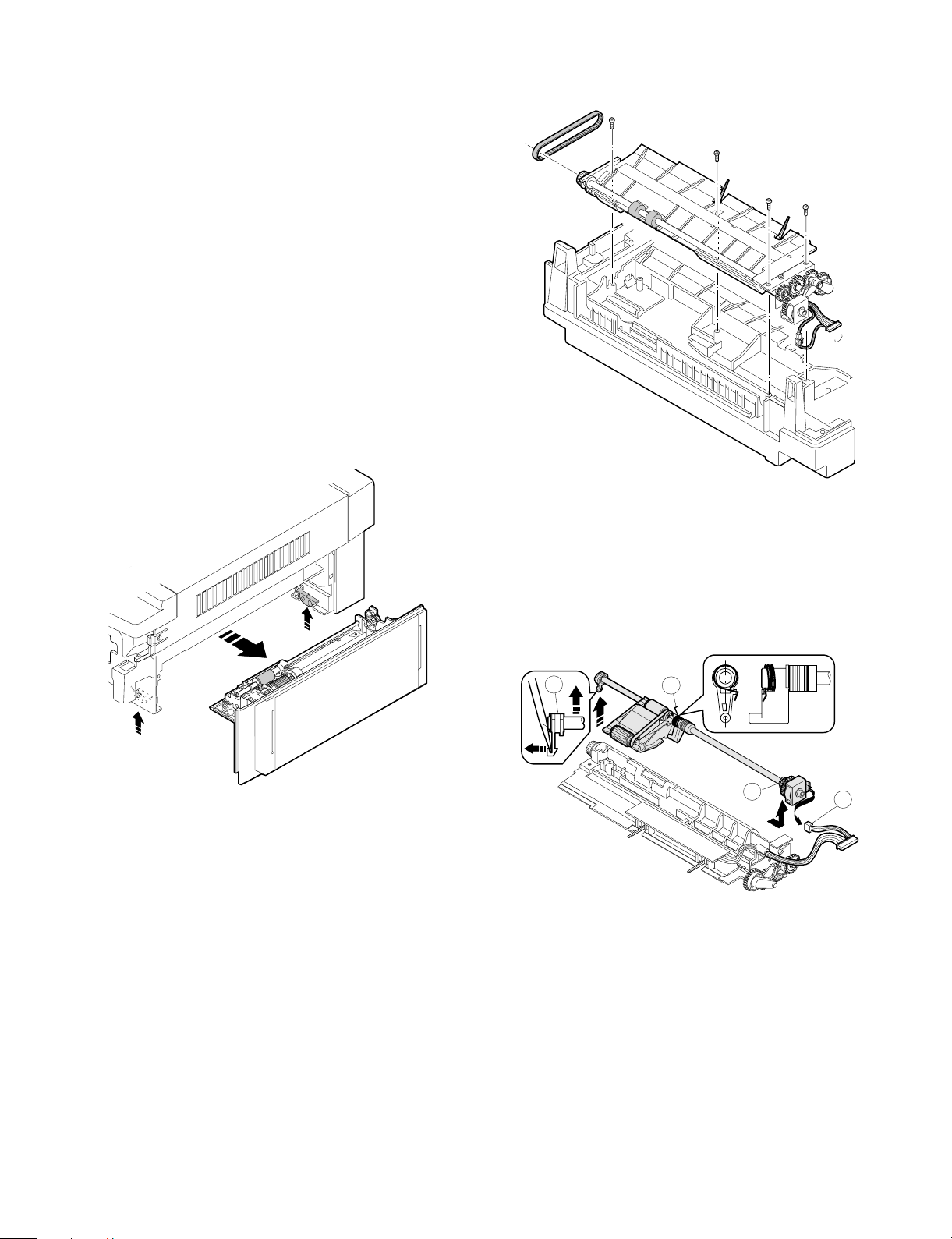
3. Fuser section
3-1. Fuser unit removal
1 Open the front panel
2 Remove the table glass.
3 Turn the open/close lever to the right and open the upper unit
slowly.
4 Remove the connectors (2 pin × 2), slightly lift the right side of the
unit and pull it out.
5 Move the copy lamp unit to the left of the body (the paper exit
side).
6 Disconnect the connector (2-pin) of the dehumidifier heater which
extends from the dark box cover. Insert a long screwdriver (+) into
that port and remove the screw which is fixing the fuser cover.
7 Remove the fuser cover in the direction of arrow A.
8 Remove an E-ring and two connectors.
3-2. Heater lamp replacement
1 Remove the fuser cover fixing screw (1 pc.), and slide it to the
front side, and remove it.
2 While pushing the projection of the Faston terminal connected to
the thermostat, remove the lead wire from the connected section.
3 Remove the lamp holder fixing screw on the top of the rear frame,
and remove the holder.
4 Pull out the heater lamp from the front frame.
For assembly, reverse the disassembly procedures.
A
6 – 6
Page 35

3-3. Upper heat roller ass’y removal
1 Remove the bearing fixing screws (2 pcs.) in the front and the rear
frames.
2 Put the paper guide to the paper exit side and separate the
separation pawl from the roller and fix it.
3 Rotate the fixing screw section of the bearing about 45 degrees
below and pull it upwards.
For assembly, reverse the disassembly procedures.
3-5. Lower cleaning roller and lower heat roller
replacement
1 Remove the fuser unit.
2 Remove the CL roller springs (2 pcs.) which is fixing the lower
cleaning roller from the hook section.
3 Remove the lower cleaning roller.
4 Lift the paper exit guide, and remove the lower heat roller without
making contact between the roller and the scraper.
For assembly. reverse the disassembly procedures.
3-4. Upper separation pawl replacement
1 Remove the fuser unit and remove the cover.
2 Place the fuser unit so that the paper guide is in the lower side.
(The separation pawl is in the upper side.)
3 Remove the tension spring, hold the tip of the separation pawl and
remove it from the supporting section, and tilt it to remove.
For assembly, reverse the disassembly procedures.
6 – 7
Page 36

3-6. Scraper replacement
1 Remove the upper fuser unit.
2 Remove the paper exit paper guide fixing screw (step screw) in
the front frame side, and remove the paper exit paper guide.
Paper exit paper guide
3 Remove the scraper hook section from the paper exit paper guide,
and remove the scraper.
3-7. Thermistor/thermostat removal
Press this projection to desassemble
* Note for assembly
• Be sure to bring the thermistor center into contact with the heat
roller.
• Clean and remove foreign materials from the thermistor surface
with alcohol.
Scraper
Note: When attaching the scraper, be careful not to deform it. Also
be careful to check that the scraper hook section is completely
inserted into the paper exit paper guide.
6 – 8
Page 37

4. Optical system
4-1. Copy lamp replacement
1 Open the body up. Release the lock lever of the manual paper
feed unit and remove the manual paper feed unit.
2 Remove the fixing screws (2 pcs.) in the right upper cabinet, and
remove the right upper cabinet.
3 Remove the fixing screws (4 pcs.) of the glass holder, and remove
the glass holder.
4 Remove the table glass.
4-2. Copy lamp unit replacement
1 Remove the manual paper feed unit, the right upper cabinet, the
glass holder, the table glass, and the operation panel.
2 Move the copy lamp unit to the frame notch (refer to the figure).
3 Remove the terminal section of the copy lamp lead wire. (One
screw and insertion terminal)
4 Loosen the fixing screw of the front and the rear frame wire, fixing
plate and remove the wire from the copy lamp unit.
5 Slide the whole unit forward, and remove the rear frame side
upwards.
For assembly, reverse the disassembly procedures.
Wire fixing screw
5 While pushing the copy lamp electrode in the rear frame, remove
the copy lamp.
For assembly, reverse the disassembly procedure.
Note: Be careful to the direction of the copy lamp installation. The
projection must be in the rear side. Attach as shown in the
figure.
Copy lamp
Fron t side R ear s ide
Main reflector
Projection
Copy lamp
Projection
Projection
Note: When the copy lamp unit is removed, the position adjustment
must be required when attaching again. Refer to the adjustment item for the work.
4-3. Mirror base drive wire replacement
<Removal>
1 Remove the manual paper feed unit, the right upper cabinet, the
glass holder, the table glass and the operation panel.
2 Remove the fixing screws (2 pcs.) of the left upper cabinet, and
slide to the rear frame side to remove the cabinet.
3 Loosen the fixing screw of the copy lamp unit wire fixing plate, and
remove the wire from the unit.
4 Remove the tension spring (7 in the figure) of the mirror base
drive wire in the paper exit side from the hook section.
5 Slightly shift the mirror base to the paper feed side, and remove
the terminal 1 of the mirror base drive wire.
6 Remove the wire fixing screw of the drive pulley.
<Installation>
1 Set the mirror base to the positioning plate position.
2 Set the terminal side of the mirror base drive wire on the hook
section 1, turn the mirror base pulley 2 outside to wind the wire
around the drive pulley from the above.
3 Wind the wire 8 turns from the outside to the inside of the drive
pulley, and put the 7th turn into the groove, and fix it with a screw
temporarily.
4 Pass the wire under the mirror base and wind around the paper
exit pulley (the larger one).
5 Pass the wire to the inside of the mirror base pulley, and pass
through the paper exit pulley (the smaller one), then fix the tension
spring to the hook section 7.
6 Check that the mirror base is in contact with the positioning plate,
and tighten the wire fixing screw of the drive pulley.
6 – 9
Page 38

2
5
7
7
5
6
4
2
5
2
4
2
6
3
5
1
1
3
Note: After replacement of the mirror base drive wire, perform the
vertical skew copy adjustment, the focus adjustment, and the
horizontal skew copy adjustment.
4-4. No. 4/5 mirror unit replacement
1 Remove the manual paper feed unit, the right upper cabinet, and
the table glass.
2 Remove the dark box cover fixing screw (1 pc.) and remove the
cover.
3 Remove the mirror holder spring.
4 Remove the shaft mounting plate, pull out the shaft towards the
paper feed side, and remove No. 4/5 mirror unit.
4 Remove connector B between the mirror motor and the main
PWB (CN-C).
5 Remove two snap bands C which are binding cables of the
operation panel.
6 Remove the optical unit .
C
A
B
A
4-5. Optical unit removal
1 Remove the drum unit and the developer unit.
2 Remove the right cabinet, the left cabinet, the operation panel, the
medium cabinet, and the rear cabinet.
3 Remove three connectors A from the sensors in the rear as
shown in the figure.
6 – 10
Page 39

4-6. Other parts in the optical system
1 Remove the rear upper cabinet.
2 Remove the CN-C connector of the main PWB and the fixing
screws (2 pcs.), and pull out the mirror motor towards the rear
frame.
3 Remove the connector and the fixing screw (1 pc.), and remove
the mirror home position sensor (MHPS) towards the rear frame.
5 Remove the connector, the manual paper feed unit, the right
upper cabinet, the table glass, and the dark box cover. Remove
the fixing screw from the above and remove the AE sensor
towards the front frame side.
4 Remove the fixing screw (1 pc.) of the upper frame and the screw
and the connector in the rear frame, then remove the main PWB.
For assembly, reverse the disassembly procedures.
6 – 11
Page 40

4-7. Light adjustment plate/temperature fuse
removal
1 Remove the document glass.
2 Remove the parts as shown in the figure.
5. Drum section
5-1. Drum cartridge removal
1 Open the front cover.
2 While pressing down the release lever A, open the toner
cartridge slowly. (Arrow B)
3 Grasp the handle on the drum cartridge, depress and hold the
release lever C on the cartridge, and pull the cartridge out of the
copier. (Arrow D)
A
C
B
D
6. Developer section
6-1. Developer unit removal
1 Open the front cover.
2 While pressing down the release lever, open the toner cartridge
slowly and remove it.
3 Loosen the step screw A.
4 Pull out the developer unit.
6 – 12
A
Page 41

6-2. Developer cartridge removal
1 Place the magnet roller of the developer unit on the box to protect
it.
2 Remove two screws C and remove the motor.
2 As shown in the figure below, open the section which is pressing
the cartridge pawl with a screwdriver, and pull out the developer
cartridge.
6-3. Toner motor removal
1 Remove four short screws A and one long screw B, and the
connector, and separate the toner cartridge section.
6-4. Toner density sensor
6 – 13
Page 42

7. Operation pan el sect io n/med iu m
cabinet
1 Open the front cabinet.
2 Remove three screws A and two harnesses from the operation
panel.
3 Remove the operation panel unit.
A
A
B
A
B
8-2. Optical unit cooling fan removal
1 Remove the rear cabinet.
2 Remove as shown below.
4 When removing the medium cabinet, first remove the process unit
and the developer unit then remove four screws B and remove
the medium cabinet.
8. Major parts in th e frame side
8-1. Ozone filter
1 Remove the document glass.
2 Remove the black sheet and remove the ozone filter.
6 – 14
Page 43

8-3. Ventilation fan motor
1 Remove the optical unit. (For details, refer to "4. Optical unit
removal.")
2 As shown in the figure below, remove the ventilation fan motor.
8-4. Transport roller clutch
1 Remove the rear cabinet.
2 Remove the transport clutch as shown in the figure below.
8-5. Paper exit sensor
1 Open the front panel.
2 Move the open/close lever to the right and open the upper unit
slowly.
3 Remove the sensor as shown in the figure below.
6 – 15
Page 44

[7] ADJUSTMENTS
The descriptions of this chapter are divided into the following sections:
1. Developer section
(1) MG roller main pole position adjustment
(2) Adjustment of clearance between DV doctor and MG roller
2. Optical section
(1) Lens unit angle adjustment
(2) Mirror unit angle/position adjustment
(3) Image distortion adjustment
(4) Copy image center position adjustment
(5) Focus adjustment
(6) Copy magnification ratio adjustment
(7) Uniformity adjustment
(8) Image loss/void area adjustment
3. Copy density adjustment
(1) Copy Density adjustment timing
(2) Note for copy density adjustment
(3) Necessary thing for copy density adjustment
(4) Copy density adjustment mode
(5) Copy density adjustment procedure
(6) Copy density adjustment table
4. Others
(1) Transfer charger wire installation
(2) DV bias adjustment
(3) Separation charger output adjustment
2 Tie a string to a needle as shown in the figure below.
3 Hold the string and move the needle to the MG roller.
4 Mark the point where the needle makes contact with the MG
roller.
Marking
5 Measure the distance between the marking and the developer unit
bottom A and check that the distance is within 15.1mm. If the
measured distance is outside the range, loosen the MG adjustment plate fixing screw, and move the adjustment plate in the
arrow direction to perform procedures 3 to 5 again.
1. Developer section
(1) MG roller main pole position adjustment
If the MG roller main pole position is improper, the following troubles
may occur:
• Insufficient copy density
• Toner splash
1 Remove the DV unit from the body and remove the DV cover.
DV cover
A
15.1mm
6 Tighten the MG adjustment plate fixing screw.
7 – 1
Page 45

(2) Adjustment of clearance between DV doctor
and MG roller
If the clearance between the DV doctor and the MG roller is improper,
the following troubles may occur:
• Insufficient copy density
• Copy dirt
• Toner splash
1 Remove the DV cover.
2 Loosen the DV doctor fixing screw.
3 Insert a 0.6mm thickness gauge into the clearance between the
MG roller and the DV doctor in the range of 30mm width under the
DV doctor fixing screw.
A
4 Press the DV doctor in the arrow direction and tighten the DV
doctor fixing screw.
5 Check that the clearance of the DV doctor is 0.6 ±0.03mm in the
range of 30mm width under the DV doctor fixing screw.
0.6±0.03mm
MG
30mm
30mm
2. Optical section
A. Adjustments list
Classification No. Adjustment content
Copy picture quality
For details, refer to the Ref. page.
*
(1)
Image distortion adjustment
(2)
Copy image center position adjustment
(3)
Focus adjustment (Resolution
adjustment)
(4)
Uniformity adjustment
(5)
Image loss, void area adjustment
A
a
b
a
b
Note: When adjusting, be careful not to scratch the DV doctor.
Adjustment
value/Standard
value
Horizontal image distortion adjustment
Vertical image distortion adjustment
Copy image loss adjustment
Void area adjustment
— — 7-4
— — 7-6
— — 7-9
— — 7-9
* — 7-10
+3
0
mm — 7-11
−0
Necessary
special tool
Ref.
page
7-8
B. Notes
When performing the adjustment, observe the following notes:
1) Observe the sequence of procedures shown in the flowchart
below.
2) Adjustment can be started midway in the flowchart only if all the
previous items have been properly adjusted.
3) If the content of an adjustment item in the flowchart is changed,
all the following items must be adjusted accordingly.
Any adjustment item is based on the previous adjustment items
and relates to the following adjustment items.
4) "Sim" in the flowchart stands for "Simulation."
7 – 2
START
Fix the blank lamp to the center.
Fix the lens center position adjustment
rail at the center temporarily.
Fix No.4/5 mirror position to the
center.
End
Page 46

1'
2'
Make a test chart. (Draw a rectangle
on A4 or 8 1/2" x 11" paper.)
With the document cover open,
make a copy on A4 or 8 1/2" x 11"
paper.
NO
Check horizontal image distortion.
The
distances at the
right and the left of the horizontal
copy image line and the black background
made by the blank lamp are equal
to each other.
YES
With the document cover closed,
make a 10% copy on A4 or
8 1/2" x 11" paper.
Check that the right corner and the left
corner angles of the copy image are
right angles.
Is the
right corner angle
of the copy image equal
to the left corner
angle ?
YES
With the document cover closed,
make a copy on A4 or 8 1/2" x 11"
paper.
Change the relative positions of
the rear or the front frame side
NO
scanner drive pulley and the
shaft, and adjust horizontal
image distortion.
Change the height balance of
right and left scanner slide rails,
NO
and adjust so that the corner
angles of the copy image
rectangle are equal to each
other.
Use the test chart (UKOG-0089CSZZ)
or the resolution chart to make a copy
on A4 or 8 1/2" x 11" paper so that the
resolution patterns are copied at the
center and the four corners.
Check the resolution at the center
and the four corners.
Is the center
resolution more than
5.0 lines/mm and are the corner
resolutions more than
4.5 lines/mm ?
YES
Set the scale along the document
reference plate (vertical to the paper
transport direction) and make a 100%
copy on A4 or 8 1/2" x 11" paper.
Compare the scale and its copy
image size.
Are they the same size ?
YES
3
Change No.4/5 mirror positions
NO
to adjust focus.
Set the Sim48-1 se t value s m a l ler.
NO
Is the copy
image greater than the
actual scale ?
3'
Set the Sim48-1 set value greater.
YES
NO
Check the copy image vertical
distortion.
Are the
four angles of the copy
image rectangle right
angles ?
Make a test chart. (Draw a rectangle at
the center of A4 or 8 1/2" x 11" paper in
the longitudinal direction.)
Set the test chart to the document
positioning reference plate, and make
a copy on A4 or 8 1/2" x 11" paper by
cassette paper feed.
Check that the copy image is at the
center of the copy paper.
Is the
copy image at the
center of the copy
paper ?
//9/
YES
YES
2
Change No. 4/5 mirror height
NO
balance and adjust vertical
image distortion.
Change the lens position so
NO
that the copy image comes at
the center of the copy paper.
Use a half-tone document and make a
copy on A4 or 8 1/2" x 11" paper in
the half tone mode.
Check the uniformity.
Is the uniformity OK ?
YES
Put the scale to the document
reference plate and set in the paper
transport direction.
Set the Sim45 set value to "0."
Make a copy with Sim50-1.
Measure the distance between the
copy image lead edge and the copy
paper lead edge.
0 ± 0.5 mm ?
Change the installing position of
NO
the exposure adjustment plate
to adjust the uniformity.
Change the Sim50-1 set value
NO
B so that the difference is
within the specified range.
7 – 3
End
Page 47

C. Adjustment contents
(1) Image distortion adjustment
There are following two types of image distortion.
Horizontal image distortion
*
Vertical image distortion
*
Image distortion is generated mainly by insufficient parallelism of the
mirror and misalignment of the lens optical axis.
In this model, image distortion is adjusted by adjusting parallelism of
each mirror.
a. Horizontal image distortion adjustment
I. Summary
This adjustment is to adjust horizontal image distortion by setting
the horizontal optical axis of the copier and the horizontal optical
axis of each mirror in parallel with each other. The relative positions of the front frame and the scanner unit drive pulley of the
frame are changed to perform the above adjustment.
Install the No. 1 and No. 2 scanner units to the specified positions, adjust the mechanical horizontal parallelism, and perform
the final adjustment while making copies.
II. Purpose
The purpose of this adjustment is to reduce horizontal image
distortion by setting the horizontal optical axis of the copier and
the No. 1 and No. 2 scanner unit horizontal optical axis in parallel with each other.
III. Note
Before starting this adjustment, the following items must have
been completed. If not, this adjustment cannot reduce image
distortion.
The lens unit right angle adjustment must have been com-
*
pleted.
The No. 4/5 mirror unit right angle adjustment must have
*
been completed.
IV. Cases when the adjustment is required
1) When the No. 1 and No. 2 scanner units are disassembled or
their part is replaced.
2) When the scanner unit drive section is disassembled or its
part is replaced.
3) When the copy image is distorted as shown below:
VI. Adjustment procedure
1) Remove the right upper side cabinet and the document reference plate.
Document
reference plate
Document table glass
Right upper side cabinet
2) Remove the document glass.
3) Loosen the fixing screw of the No. 1 scanner unit wire.
Wire fixing screw
Document Copy A Copy B
V. Necessary tools
Screwdriver (+)
*
Hex wrench
*
Scale
*
Test chart for distortion adjustment (Make a chart shown
*
below by yourself.)
Draw a rectangle on a paper (A4 or 8 1/2" x 11") as shown
below.
Be sure to make four right angles.
L
L
L=50mm
7 – 4
Page 48

4) Manually turn the scanner unit drive gear to bring No. 2
scanner unit into contact with No. 2 scanner unit positioning
plate. When No.2 scanner unit makes contact with No.2
scanner unit positioning plate in the rear frame side simultaneously, the mechanical parallelism of No.2 scanner unit is
proper.
If one side of No.2 scanner unit makes contact with No.2
scanner unit positioning plate and the other side does not,
the parallelism is improper.
If the parallelism is improper, perform the procedure of step
5).
(Note)
Allow a clearance of about 0.5mm between the scanner
unit drive pulley and the positioning E-ring.
0.5mm
7) Manually turn the scanner unit drive gear to bring No.2
scanner unit into contact with the positioning plate, and
perform the procedure of step 4).
Repeat procedures of steps 4) to 7) until the parallelism of
No.2 scanner unit is properly set.
8) With No. 2 scanner unit being in contact with No. 2 scanner
unit positioning plate, bring No.1 scanner unit into contact
with No.1 scanner unit positioning plate, and fix it to the
scanner unit drive wire.
5) Loosen the scanner unit drive pulley setscrew in the side
where No.2 scanner unit does not make contact with No.2
scanner unit positioning plate.
Set screw
Scanner unit drive pulley
6) Without moving the scanner unit drive pulley shaft, manual-
ly turn the scanner nit drive pulley in the same side of the
loosened setscrew. When it makes contact with No.2 scanner unit positioning plate, tighten and fix the setscrew.
Do not move
the shaft.
No.1 scanner unit
Positioning
plate
Wire fixing screw
No.2 scanner unit
Positioning plate
Scanner unit drive pulley
7 – 5
Page 49

Procedures 1) to 8) are for adjustment of mechanical
horizontal parallelism. No.1 scanner unit and No.2 scanner
unit are fixed to the specified positions and the mechanical
horizontal parallelism of No.2 scanner unit is adjusted.
(When No.1 and No.2 scanner units are shifted to the right
end, the scanner units are in contact with the four positioning plates.)
12) Without moving the scanner unit drive pulley shaft, manually turn the scanner unit drive pulley whose setscrew was
loosened, and adjust the parallelism of No.1 and No.2
scanner units.
No.2
scanner
unit.
No.1
scanner
unit
Then the optical horizontal parallelism must be adjusted in
the following procedures.
9) Set the A3 or 11" x 17" paper along the guide which is
located this side on the document table and make a copy.
10) Check the horizontal image distortion.
If LL = LR, there is no horizontal distortion.
Distance between the copy
horizontal line and the outer
edge of the black background
Black background
LL
LL and LR =
LR
11) If LL is not equal to LR, perform the following procedure.
Loosen the setscrew of the scanner unit drive pulley in the
front or the rear frame.
Set screw
Scanner unit drive pulley
Do not move the shaft.
13) Tighten the set screw of the scanner unit drive pulley.
14) Check the image distortion in the same manner as step
10).
Repeat procedures 11) to 14) until horizontal image distortion is eliminated.
VII. Troubles caused by improper adjustment
b. Vertical image distortion adjustment
I. Summary
This adjustment is to adjust parallelism of the vertical optical axis
of the copier and that of each mirror to eliminate vertical image
distortion.
For adjusting vertical image distortion, the overall adjustment
and the right-left balance adjustment must be performed independently.
The overall adjustment is performed by changing the height of
No.4/5 mirror unit in the front frame side. The right-left balance
adjustment is performed by changing the right-left balance of
No.2 scanner unit rail.
The right-left balance adjustment must be performed in advance
to the overall adjustment.
II. Purpose
The purpose of this adjustment is to set parallelism of the vertical optical axis of the copier and that of No.4/5 mirror unit and
No.2 mirror unit to eliminate vertical image distortion.
III. Note
Before performing this adjustment, the following adjustments
must have been completed.
If not, this adjustment cannot be performed properly.
The lens unit right angle adjustment
*
No.4/5 mirror unit right angle adjustment
*
Horizontal image distortion adjustment
*
IV. Cases when the adjustment is required
1) When No.4/5 mirror unit is disassembled or its part is
replaced.
2) When the scanner unit drive section is disassembled or its
part is replaced.
3) When the copy image is distorted as follows:
Scanner unit drive pulley
Document Copy C Copy D
7 – 6
Page 50

V. Necessary tools
Screwdriver (+)
*
Screwdriver (–)
*
Scale
*
Test chart for distortion adjustment (Make by yourself.)
*
Draw a rectangle on A4 or 8 1/2" x 11" paper as shown
below:
Be sure to make four right angles.
L
LL
L = 10mm
L
VI. Adjustment procedure
1) Set the test chart for image distortion adjustment on the
document glass, and make a normal copy on a paper of A4
or 8 1/2" x 11".
2) Check image distortion in the right and the left sides.
If the both vertical lines are in parallel with each other, the
right-left distortion balance is proper. (However, there may be
some distortion.)
If all the four angles are right angles, there in no distortion
and the following procedures are not required.
Large
distortion
Small
distortion
Change the right side
height of the rail.
Change the left side
height of the rail.
Scanner unit fixing screw
Scanner unit rail
Repeat procedures 2) and 3) until the right-left balance of
image distortion is proper.
4) Change the height of the roller in No.4/5 mirror unit front
frame side to adjust the vertical image distortion.
If the copy image is tilting as shown in sample (X) below,
lower No.4/5 mirror unit. If it is tilting as shown in sample (Y)
below, lift No.4/5 mirror unit.
3) If the right-left distortion balance is improper, loosen the
fixing screw of No.2 scanner unit rail to change and adjust
the right-left balance of No.2 scanner unit rail.
(Note)
This procedure is to have the balance between the right
image distortion and the left image distortion, which does not
mean to eliminate the image distortion. Change the height of
No.2 scanner unit rail in the greater distortion side.
If the distortion in the lead edge side (when viewed in the
paper transport direction) is greater, change the height of the
left rail of No.2 scanner unit.
If the distortion in the rear edge side (when viewed in the
paper transport direction) is greater, change the height of the
right rail of No.2 scanner unit.
(X) (Y)
5) Make a copy to check the vertical image distortion.
If the four angles are right angles, the adjustment is completed.
Repeat procedures 4) and 5) until the vertical image distortion is eliminated.
(Note)
If a vertical image distortion is not eliminated with procedure
4), change the overall height of No.2 scanner unit rail. Then
repeat procedures 1) to 5).
VII. Troubles caused by improper adjustment
7 – 7
Page 51

(2) Copy image center position adjustment
I. Summary
The optical axis is changed by changing the lens unit position to
optically align the document table and the vertical position of the
copy image on the copy paper.
When the lens unit position is changed, the lens position in the
front and the rear frame direction is changed to change the
optical axis.
As a result, the document table is optically aligned with the copy
image on the copy paper.
II. Purpose
The purpose of this adjustment is to set the copy image center
at the vertical center of the copy paper.
III. Note
Before performing this adjustment, the following adjustment
must have been completed. If not, this adjustment cannot be
performed properly.
No.4/5 mirror unit right angle adjustment
*
Image distortion adjustment
*
IV. Cases when the adjustment is required
1) When the lens unit is disassembled or its part is replaced.
2) When the copy image is shifted from the vertical center of the
paper.
V. Necessary tool
Screwdriver (+)
*
Scale
*
Test chart for center position adjustment (Make a chart
*
shown below by yourself.)
Draw a line in the paper transport direction at the center of A4
or 8 1/2" x 11" paper.
4) If the image of the line is not at the center of the paper,
perform the following procedure.
5) Remove the right side cabinet and the document reference
plate.
Document
reference plate
Document table glass
Right upper side cabinet
6) Remove the document glass.
7) Remove the optical unit cover.
8) Loosen the lens rail fixing screw, and slide the lens unit back
and forth.
9) Make a copy and check that the image line is at the center of
the paper. If not, repeat the procedures 1) to 9) until the
image line comes at the center of the paper.
VII. Troubles caused by improper adjustment
Center
Copy paper
(A4 or 8 1/2" x 11")
VI. Adjustment procedure
1) Set the test chart for center position adjustment at the document reference position.
2) Make a copy on A4 or 8 1/2" x 11" paper.
3) Check that the image of the line is at the center of the paper.
(Standard: 0±1.5mm)
1.5mm or less
(Copy A)
Shift
1.5mm or less
(Copy B)
Shift
Copy image
Folding of copy paper
Folding of copy paper
Copy image
(3) Focus adjustment (Resolution adjustment)
I. Summary
The distance between the document and the photoconductor
drum is changed by changing No.4/5 mirror unit drive lever position to adjust the focus.
II. Purpose
The purpose of this adjustment is to correct the lens variations
and the optical section dimensional variations to have good copy
images with a proper focus.
III. Note
Before performing this adjustment, the following adjustment
must have been completed. If not, this adjustment cannot be
performed properly.
Image distortion adjustment
*
IV. Cases when the adjustment is required
1) When the lens or the mirror unit is disassembled or any one
of their parts is replaced.
2) When the scanner unit drive section is disassembled or its
part is replaced.
3) When a cop image of improper focus is obtained.
V. Necessary tools
Screwdriver (+)
*
Test chart (One with the resolution adjustment chart)
*
7 – 8
Page 52

VI. Adjustment procedures
1) Set the test chart on the document table.
2) Make a normal copy on A4 or 8 1/2" x 11" paper.
3) Check that resolutions at the copy paper center and the four
angles are as shown in the table below:
(Standard) (Unit: lines/mm)
Copy center Corner
Normal (100%) 5.0 4.5
Enlargement 5.0 4.5
Reduction 4.5 3.6
(Copy)
Check
the corners.
4.5
5.0
5.6
6.3
7.1
4.0
8.0
9.0
9.1
9.2
9.2
9.2
9.2 9.2
7) Loosen No.4/5 mirror unit drive lever fixing screw, and adjust
the No.4/5 mirror unit position.
2.8
3.2
3.6
If any resolution is out of the above specifications, perform
the following procedures.
4) Remove the right cabinet and the document reference plate.
Document
reference plate
Document table glass
Right upper side cabinet
5) Remove the document glass.
6) Remove the optical unit cover.
Optical unit cover
8) Make a copy and check that the resolutions are in the
specified range.
If any resolution is out of the specified range, repeat procedures 1) to 8).
9) Put the No.4/5 mirror drive lever to the base plate side and
tighten the fixing screw.
VII. Troubles caused by improper adjustment
7 – 9
Page 53

(4) Uniformity adjustment
I. Summary
The uniformity adjustment is performed by changing the exposure plate position attached to No.1 scanner unit.
The above procedure changes the balance of light quantity
radiated onto the document.
II. Purpose
The purpose of this adjustment is to have uniform copy density.
III. Note
When this adjustment is performed, the exposure will be
changed. Therefore, the copy density adjustment must be performed after this adjustment. Also, this adjustment must be performed always before the copy density adjustment.
IV. Cases when the adjustment is required
1) When the reflector is replaced.
2) When the copy lamp is replaced.
3) When the exposure adjustment plate is disassembled or
replaced.
4) In maintenance
V. Necessary tools
Screwdriver (+)
*
A4 or 8 1/2" x 11" paper
*
Half-tone paper of A4 or 8 1/2" x 11" or larger
*
VI. Adjustment procedure
1) Set a half-tone paper of A4 or 8 1/2" x 11" on the document
table.
2) Set the exposure level to the min. level in the photo mode,
and make a copy on A4 or 8 1/2" x 11" paper.
3) Check the uniformity. If there is any unevenness, perform the
following procedures.
4) Move the exposure adjustment plate of the lighter copy section towards Y or move the exposure adjustment plate of the
darker copy section towards X.
(Example)
If a copy shown below is made, move the front frame side of
the sub exposure adjustment plate in the direction of X to
adjust the exposure balance.
Less exposure
(Dark copy)
Paper exit
direction
Half-tone copy
[Fig. 1]
Y
X
5) Make a copy in the same manner as procedure 2), and
check the uniformity.
Repeat procedures 1) to 5) until proper uniformity is obtained.
VII. Troubles caused by improper adjustment
Y
X
Y
X
(5) Image loss/void area adjustment
The image loss/void area adjustment is performed by the combination
of the copied image position adjustment on the copy paper and the
void area adjustment.
Since the image loss and the void area are closely related each other,
they must be adjusted simultaneously.
(Definitions of image loss and void area)
Void area: Empty (white) area on a copy paper (without toner on it)
Image loss: The qua nt it y (le ng th) of an imag e los t on a cop y pa pe r .
(Document)
(Copy)
Paper lead
edge
Li
Li: Lead edge image loss
Lv
Lv: Lead edge void area
(In some cases, Lv
a. Copy image loss adjustment
I. Summary
In order to adjust the copy image position on a copy paper, the
lead edge position of an image on the photoconductor for the
lead edge position of a document on the document table is
changed with simulations 50-1, and the relative position of the
paper to the image position on the photoconductor is changed.
In the models which have no zoom copy functions, however, the
lead edge position of an image on the photoconductor for the
lead edge position of a document on the document table is not
changed.
The relative position of the paper is changed at OFF timing of
the scanner home position sensor after starting scanning to adjust the copy image position on the paper.
After adjusting the copy image position with the above procedure, the blank lamp OFF timing for the lead edge position of an
image on the photoconductor is changed with simulations 45-1
to adjust the void area.
II. Purpose
The purpose od this adjustment is to improve separation in the
Y
X
photoconductor section and in the fuser section and reduce dirt
on the fuser section pawl by obtaining the max. effective copy
area and the proper void area.
III. Note
If the proper void area is not obtained, the separation ability in
the photoconductor section may be degraded and dirt on the
fuser section pawl may be increased.
Before performing this adjustment, the following adjustment
must have been completed. If not, this adjustment cannot be
performed properly.
Adjustment of paper pressure against the resist roller (Sim
*
51-2 set value must be properly set.)
IV. Cases when the adjustment is required
1) When the optical section is disassembled or its part is
replaced (including the scanner home position sensor).
>
Lv)
=
7 – 10
Page 54

2) When the main PWB is replaced.
3) When the RAM in the main PWB is replaced.
4) When "U2" trouble occurs.
5) When the resist roller unit is disassembled or replaced.
V. Necessary tools
Screwdriver
*
Scale
*
Test chart
*
VI. Adjustment procedure
(Copy image position adjustment)
1) Execute simulations 45. (C → 0→ 0 → C→ 45 → CB)
Simulations 45 is to adjust the size of the void area in the
lead edge of the copy paper.
The set adjustment value is displayed on the COPIES
SELECTED display.
2) Set the set value of simulations 45 to "0."
Enter "0" with the numeric key and press PRINT button.
3) Execute simulations 50-1. (C → 0 → 0 → C → 50 → CB → 1
→ CB)
This simulations is to adjust the copy image position for the
paper. The currently set adjustment values is displayed on
the COPIES SELECTED display.
Adjustment value B: Corresponds to the time interval from
the scanner unit starting and the scanner home position sensor OFF to the
resist roller ON.
According to this value, the paper feed
timing for the image on the photoconductor drum is changed and the copy
image position on the copy paper is
also changed.
When the set value is changed by "1,"
the position of the copy image on the
copy paper is changed by about 0.123
mm.
When the set value is made greater,
the copy image position for the copy
paper moves backward. When the set
value is made greater, the copy image
position for the copy paper moves forward.
Use the paper tray select key to select the display of adjustment value B and to select the set mode.
Display lamp Display content/set mode
Copier tray cassette paper feed
lamp BLINKS
Adjustment value B
4) Press the scale onto the document alignment plate and set it
horizontally as shown below:
Scale
5) Execute simulations 50-1 to make several copies.
6) Make a copy, and check that the copy image lead edge is in
the range of 0 ±1.5 mm from the paper lead edge position
reference.
If it is out of the above range, change adjustment value B
and repeat procedure 6) until it is within the above range.
VII. Troubles caused by improper adjustment
b. Void area adjustment
I. Summary
The copy image position on the copy paper is adjusted with
simulations 50-1, then the main corona grid ON timing for the
image lead edge on the photoconductor is changed with simulations 45 to adjust the void area.
In concrete, in the case of the document table mode, the adjustment is performed by changing the time interval from the scanner motor ON to the main corona grid ON.
II. Purpose
The purpose od this adjustment is to improve separation in the
photoconductor section and in the fuser section and reduce dirt
on the fuser section pawl by obtaining the max. effective copy
area and the proper void area.
III. Note
If the proper void area is not obtained, the separation ability in
the photoconductor section may be degraded and dirt on the
fuser section pawl may be increased.
Before performing this adjustment, the following adjustment
must have been completed. If not, this adjustment cannot be
performed properly.
Adjustment of paper pressure against the resist roller (Sim
*
51-2 set value must be properly set.)
IV. Cases when the adjustment is required
1) When the optical section is disassembled or its part is
replaced (including the scanner home position sensor).
2) When the main PWB is replaced.
3) When the RAM in the main PWB is replaced.
4) When "U2" trouble occurs.
5) When the resist roller unit is disassembled or replaced.
V. Necessary tools
Screwdriver
*
Scale
*
Test chart
*
Black background document
*
7 – 11
Page 55

VI. Adjustment procedure
(Copy image position adjustment)
1) Execute simulations 45. (C → 0 → 0 → C → 45 F128Ä CB)
Simulations 45 is to adjust the size of the void area in the
lead edge of the copy paper.
The set adjustment value is displayed on the COPIES
SELECTED display.
2) Set the set value of simulations 45 to "0."
Enter "0" with the numeric key and press PRINT button.
3) Execute simulations 50-1. (C → 0 → 0 → C → 50 → CB → 1
→ CB)
This simulations is to adjust the copy image position for the
paper. The currently set adjustment values is displayed on
the COPIES SELECTED display.
Adjustment value B: Corresponds to the time interval from
the scanner unit starting and the scanner home position sensor OFF to the
resist roller ON.
According to this value, the paper feed
timing for the image on the photoconductor drum is changed and the copy
image position on the copy paper is
also changed.
When the set value is changed by "1,"
the position of the copy image on the
copy paper is changed by about 0.123
mm.
When the set value is made greater,
the copy image position for the copy
paper moves backward. When the set
value is made greater, the copy image
position for the copy paper moves forward.
Use the paper tray select key to select the display of adjustment value B, and to select the set mode.
Display lamp Display content/set mode
Copier tray cassette paper feed
lamp BLINKS.
Adjustment value B
6) Calculate the average lead edge void area.
7) Check that the void area is within the specified range.
Void area
mm
1/2mm
10
20 30
Copy scale image
Black background edge
Paper lead edge
Standard:
+3
0
mm
−0
If the void area is outside the specified range, change the set
value of simulations 45 and repeat procedures 6) to 7).
When the set value is changed by "1," the void area is
changed by about 0.123 mm.
When the set value is made greater, the void area becomes
greater, and vise versa.
4) Set adjustment value B to "0."
Enter "0" with the numeric key and press PRINT button.
5) Press the scale onto the document alignment plate and set it
horizontally as shown below:
Scale
7 – 12
Page 56

3. COPY DENSITY ADJUSTMENT
120mm
White paper
Test char t
Front side
(1) Copy density adjustment timing
The copy density adjustment must be performed in the following
cases:
✱ When in maintenance.
✱ When the high voltage unit output current or voltage is adjusted.
✱ When the developing bias voltage is adjusted.
✱ When the copy lamp is replaced.
✱ When the optical section is cleaned.
✱ When an optical part is replaced.
✱ When the optical section is disassembled.
✱ When the photoconductor drum is replaced.
✱ When the developer is replaced.
✱ When the AE sensor is replaced.
✱ When the main control PWB is replaced.
✱ When the EEPROM on the main control PWB is replaced.
✱ When the memory trouble (U2) occurs.
✱ When a part of the copy lamp control circuit is replaced.
✱ When the AC power source PWB is replaced.
(2) Note for copy density adjustment
1) Necessary procedures before adjustment
✱ Clean the optical section.
✱ Clean the AE sensor.
✱ Clean or replace the charger wire.
✱ Check that the high voltage section voltage and the developing
bias voltage are in the specified range.
2) Note
✱ The auto mode copy density adjustment must be performed after
the normal mode copy density adjustment. Never reverse the sequence.
(4) Copy density adjustment mode
The copy density adjustment must be performed in the following five
mode:
Copy density adjustment mode Exposure level
Normal mode
Non-toner-save mode 1 5
Toner save mode 1 5
Photo mode Non-toner-save mode 1 5
Auto mode
Non-toner-save mode 1 5
Toner save mode 1 5
(5) Copy density adjustment procedure
The copy density is adjusted by using Simulations 46 to change the
exposure level and the copy lamp voltage in each copy mode.
The copy density adjustment must be performed in the five modes.
To select each mode, use the copy mode select key.
A. Test chart (UK0G-0162FCZZ) setting
1) Set the test chart and B4 (14″ × 8 1/2″) white paper on the original
table as shown below.
The sensing area of the AE sensor is about 120 mm wide from the
rear frame side edge on the original table glass. Place the white
paper on that area, but keep the test chart away from that area.
(3) Necessary items for the copy density
adjustment
✱ Test chart
(Use one of the following three: UKOG-0162FCZZ, UKOG0089CSZZ, KODAK GRAY SCALE)
✱ B4 (14″ × 8 1/2″) white paper
1 10
Test chart comparison
UKOG-0162FCZZ
DENSITY No.
UKOG-0089CSZZ
DENSITY No.
KODAK GRAY
SCALE
12345678910W
0.1 0.2 0.3 0.5 1.9 0
123419A
9
SHARP CORPORATION
MADE IN JAPAN
W2345678
B. Normal copy mode (Non-toner-save mode) copy
density adjustment
1) Enter the simulations 46 mode.
2) Set the adjustment mode to the normal copy mode (Non-tonersave mode).
(Press the copy mode select key to light the normal copy mode
lamp.)
Copy mode lamp
B5 A4
B4 B5
Copy sheet display
%
Lighting
Copy d ensity di splay lamp
12345
Copy mode
select key
Copy densi ty
adjust me nt key
122% A4 B4
115%
100%
81% B4 A4
70%
7 – 13
Page 57

3) Set the density level to "1" with the copy density adjustment key.
(The currently set copy lamp voltage level will be displayed on the
COPIES SELECTED display.)
Copy mode lamp
Lighting
Copy d ensity di splay lamp
12345
Copy mode
select key
Copy density
adjustment key
122% A4 B4
115% B5 A4
100%
81% B4 A4
70%
B4 B5
Copy sheet dis p l ay
%
4) Press the print button to make a copy.
Check the gray scale copy to insure that "6" is slightly copied and
"5" is not copied.
When the copy density is too dark, increase the copy lamp voltage
level.
When the copy density is too light, decrease the copy lamp voltage level.
Enter a new set value of the copy lamp voltage level with the
numeric keys and press the print button, then the entered value
will be set and the copy density will be adjusted according to the
set value.
1 10
23
4
567
8
9
W
Slightly copied
Not copied
5) Set the copy density level to "5" with the copy density adjustment
key.
(The currently set copy lamp voltage level will be displayed on the
COPIES SELECTED display.)
Copy mode lamp
Copy s heet displa y
B5 A4
%
Lighting
Copy de nsit y dis pl ay lam p
12345
Copy mode
select key
Copy dens i ty
adjus tment key
Lighting
122% A4 B4
115%
100%
81% B4 A4
70% B4 B5
6) Press the print key to make a copy.
Check the gray scale copy to insure that "2" is clearly copied and
"1" is not copied.
When the copy density is too dark, increase the copy lamp voltage
level.
When the copy density is too light, decrease the copy lamp voltage level.
Enter a new set value of the copy lamp voltage level with the
numeric keys and press the print button, then the entered value
will be set and the copy density will be adjusted according to the
set value.
1 10
2
34
56
78
9
W
C. Normal copy mode (Toner save mode) copy density
adjustment
1) Set the adjustment mode to the normal copy mode (Toner save
mode). (Press the copy mode select key to light the normal copy
mode lamp and the photo copy mode lamp.)
Copy mode lamp
B5 A4
B4 B5
Copy sheet display
%
Lighting
Copy d ensity di splay lamp
12345
Copy mode
select key
Copy densi ty
adjust me nt key
122% A4 B4
115%
100%
81% B4 A4
70%
Adjust in the same manner as the above copy density adjustment
procedures i the normal mode (Non-toner-save mode).
D. Photo copy mode (Non-toner-save mode) copy density
adjustment
There is no toner save mode in the photo copy mode.
1) Set the adjustment mode to the photo copy mode.
(Press the copy mode select key to light the photo copy mode
lamp.)
Copy mode lamp
B5 A4
B4 B5
Copy s heet displa y
%
Lighting
Copy d ensity di splay lamp
12345
Copy mode
select key
Copy densi ty
adjust me nt key
122% A4 B4
115%
100%
81% B4 A4
70%
Check the gray scale copy to insure that "7" is slightly copied and
"6" is not copied.
When the copy density is too dark, increase the copy lamp voltage
level.
When the copy density is too light, decrease the copy lamp voltage level.
Enter a new set value of the copy lamp voltage level with the
numeric keys and press the print button, then the entered value
will be set and the copy density will be adjusted according to the
set value.
1 10
234567
8
9
W
Slightly copied
Not copied
E. Auto copy mode (Non-toner-save mode) copy density
adjustment
1) Set the adjustment mode to the auto copy mode (Non-toner-save
mode). (Press the copy mode select key to light the auto copy
mode lamp.)
Not copied
Copied
7 – 14
Page 58

Copy mode lamp
120mm
White paper
Test char t
Front side
Lighting
Copy de nsit y dis pl ay lam p
12345
122% A4 B4
115%
B5 A4
100%
81% B4 A4
70%
B4 B5
Copy s heet displa y
%
F. Auto copy mode (Toner save mode) copy density
adjustment
1) Set the adjustment mode to the auto copy mode (Toner save
mode).
(Press the copy mode select key to light the auto copy mode lamp
and the photo copy mode lamp.)
Copy mode
select key
Copy densi ty
adjust me nt key
2) Set the density level to "1" with the copy density adjustment key.
(The currently set copy lamp voltage level will be displayed on the
COPIES SELECTED display.)
Copy mode lamp
B5 A4
B4 B5
Copy s heet displa y
%
Lighting
Copy de nsit y dis pl ay lam p
12345
Copy mode
select key
Copy dens i ty
adjus tment key
122% A4 B4
115%
100%
81% B4 A4
70%
3) Set the copy lamp voltage level set value to "0."
Enter the new set value with the numeric key and press the print
button, then the entered value will be set. (Be sure to set to "0.")
4) Set the copy density level to "5" with the copy density adjustment
key.
(The currently set copy lamp voltage level will be displayed on the
COPIES SELECTED display.)
Copy mode lamp
Copy de nsit y dis pl ay lam p
Copy s heet displa y
Copy mode lamp
Lighting
Copy d ensity di splay lamp
12345
Copy mode
select key
Copy density
adjustment key
122% A4 B4
115% B5 A4
100%
81% B4 A4
B4 B5
70%
Copy s heet displa y
%
122% A4 B4
115%
B5 A4
100%
81% B4 A4
70%
B4 B5
%
Lighting
Copy mo de
select key
12345
Copy densi ty
adjust me nt key
Lighting
5) Press the print button to make a copy.
Check the gray scale copy to insure that "3" is slightly copied and
"1" is not copied.
When the copy density is too dark, increase the copy lamp voltage
level.
When the copy density is too light, decrease the copy lamp voltage level.
Enter a new set value of the copy lamp voltage level with the
numeric keys and press the print button, then the entered value
will be set and the copy density will be adjusted according to the
set value.
1 10
5
678
9
Slightly copied
Not copied
Adjust the copy density in the same manner as the Photo copy mode
(Non-toner-save mode) copy density adjustment.
W234
7 – 15
Page 59

A : Auto copy mode N.TS : Non-toner-save mode
(6) Copy density adjustment table
P : Photo copy mode TS : Toner save mode
N : Normal copy mode
Copy mode Mode display Density level Test chart copy density
1 10 W2
34
56
1
N.TS N
Not copied
1 10
2
34
56
5
Normal
Not copied
1 10
2
Copied
34
56
1
TS N & P
Not copied
1 10
2
34
56
5
2
Copied
34
56
Not copied
1 10
78
Slightly copied
78
78
Slightly copied
78
78
9
9
9
9
9
W
W
W
W
Photo N.TS P
N.TS A
Auto
TS A & P
1
Slightly copied
Not copied
1 10
2
34
56
78
9
W
5
Not copied
Copied
1
1 10
2
34
56
78
9
W
5
Slightly copied
Not copied
1 10
2
34
56
78
9
W
1
Slightly copied
Not copied
5
7 – 16
Page 60

4. Others
(1) Transfer charger wire installation
Install the transfer charger wire as shown below. (Clean the charger
wire at every 40K copies and replace it at every 80K copies.)
Transfer charger unit (TC unit)
10 0.5
(3) Separation charger output adjustment
1) Install the DV unit and the process unit to the copier.
2) Set the digital multi mater range to DCV 100V or more.
3) Connect the high voltage probe to the lower unit PWB separation
output terminal ((+) side) and the chassis (GND).
4) Execute simulation 8-9. (The separation voltage is outputted form
30 sec.)
5) Adjust the separation voltage adjustment control (VR1) so that the
output voltage is 3.5V ±0.35V.
(Note for replacement of the charger wire)
a Do not twist or deform the charger wire.
Charger wire
Improper
Charger wire
Improper
b After replacement, be sure to clean the charger wire with alcohol.
(Be sure to use alcohol only.)
c After wiping with alcohol, wipe with a dry cloth.
d Use charger wire of 70µ (DWIR-0466CSZZ).
Cut the wire at the
Tension spring
2~3mm
root of the screw
Wind two turns and
tight en t he sc rew
(2) DV bias adjustment
1) Set the digital multi meter range to DCV 300V or more.
2) Put the test rod between the bias output faston tab terminal ((+)
side) of the lower unit PWB and the chassis (GND).
3) Execute simulation 8-1. (The DV bias voltage is outputted for 30
sec.)
4) Adjust the DV bias adjustment control (VR2) so that the output
voltage is –200V–3V.
7 – 17
Page 61

[8] SIMULATIONS
1. Outline
This model is equipped with the simulations feature which allows the
following operations with the keys on the operation panel:
1) Adjustments
2) Setting of sp ec if ic at ions and functions
3) Resetting trouble codes
4) Checking operations
2. Purpose
The purpose of the simulations feature is to improve serviceability in
repairs and adjustments.
Since the mechanical adjustments can be performed electrically, the
above purpose is achieved with low costs.
3. Opera tin g pr oc edu r e
Simulations operating procedure
Start
Press the cle a r ke y
Press the zero key
Press the zero key
Press the cle a r ke y
All l a mps and indicat ors
on the operation panel go off.
Ready for entry of the main
test command num b er
Enter the main test command
number with numeric keys
The s et adjus t ment va lue or
the counter value is displayed
on the copy quantity display
To change t he set adjustment
value or the counter value,
enter a new value with numeric
keys
The entered valu e is displayed
on the copy quantity display
Press the print key
The new set value is stored
Is there a su b co de ?
Press the prin t key
Is the test
NO
command for operati on
check?
Operat i o ns acc or ding to the
sim u l at ions are perfor med
Do you
perform anot he r
simulations?
Press the cle a r ke y
NO
YES
NO
YES
YES
Press the print ke y
"00" blinks on the copy
quantity display . Ready for
entry of the s ub c ode.
Enter the sub code with
numeric keys
Press the print key
YES
Is the main
code same?
The main sim ulations
number i s disp l ayed on the
copy quantity display
NO
Is the sub
code display?
Enter a new m ain code
The main code is display on
the copy quantity display
NO
YES
Press the clear key
All the lamps and indicators
on the operation panel go off.
Ready for entry of the main
simulations number
Press the cle a r ke y
End
8 – 1
Page 62

4. Purpose list
Purpose Section Main Sub Function Ref. page
Adjustments Paper feed section 51 2 Resist amount adjustment
Optical section 45 1 Lead edge void amount setting
46 1 Copy density (exposure level) adjustment 8-4
47 AE sensor characteristics value data auto input
50 1 Lead edge image position adjustment
Developer 8 1 Developing bias voltage check
25 2 Auto developer adjustment
Process 8 2 MC/TC output check (Normal mode)
3 MC/TC output check (Photo mode)
4 MC/TC output check (Toner save mode)
7 SC output check
9 MC/TC/SC output check
Setting Specifications 26 6 Destination setting
Paper feed section 26 12 Manual copy mode setting
Fuser section 26 13 Main motor operation mode setting at warming up
43 1 Fuser temperature setting
2 Fuser temperature setting (in power save)
Process 44 1 Correction mode setting
Counter Copy count 22 1 Maintenance counter display
2 Maintenance preset counter display
5 Total counter display
12 Drum counter display
Operation check Paper feed section 30 1 Main body sensor operation check
Optical section 1 1 Mirror base scan operation check
2 Optical system sensor operation check
5 3 Copy lamp lighting operation
Operation panel 5 1 LED lighting check
Fuser section 5 2 Heater lamp lighting check
Process 5 4 Discharge lamp lighting check
5 Blank lamp lighting check
6 2 Separation pawl auto operation check
44 2 Optical system dirt correction reference value display
3 Optical system dirt correction voltage correction value display
4 Photoconductor drum rotation time display
Developer section 10 Toner motor auto operation check
25 1 Toner density sensor operation check/toner density monitor
Trouble cancel 14 Cancel of troubles other than U2
16 U2 trouble cancel
8-3
8-5
8-6
8-7
8-8
8-9
8 – 2
Page 63

5. Details of simulations
PPD
TRC
Purpose/kind Section Main
Adjustment Paper feed
section
Optical unit 45 1 Used to adjust the copy paper lead edge void and the rear edge void amount.
Contents
Sub
code
code
51 2 Used to adjust contact pressure between paper and the main body resist
roller. (Amount of paper buckle at the resist roller)
Change the set value when the shift between the paper and the image varies.
(Operation/procedure)
When the simulation key operation is performed, the currently set value is
displayed on the COPIES SELECTED display.
Enter the set value with the numeral key and press the print button, and the
entered set value will be stored in the main PWB RAM.
The standard set value is 25.
Tray paper feed mode: Tray (upper) paper feed lamp ON
Manual paper feed mode: Manual paper feed lamp ON
The set value corresponds to the time interval between when the paper detector (PPD) in front of the main body resist roller detects paper and when the
transport roller (TRC) turns off.
The greater this time interval is, the greater the contact pressure between the
paper and the resist roller is.
(Operation/procedure)
When the simulation key operation is performed, warming-up operation is
performed. After completion of warming up, the currently set void amount is
displayed on the COPIES MADE display.
Use the tray select key to select between the lead edge void amount adjustment and the rear edge void amount adjustment mode. The upper tray lamp
will change as shown in the table below.
Mode Tray lamp
Lead edge void amount adjustment mode Upper tray lamp –
Read edge void amount adjustment mode
(Cassette)
Read edge void amount adjustment mode
(Manual feed)
Enter the set value with the numeral keys and press the PRINT button, and
the set value will be stored.
The standard set value is 50. The void area increases 0.123mm for an increase of the set value by 1.
Description
* The time interval can be set. The
greater the time interval is, the
greater the contact pressure between the paper and the resist
roller is. If the contact pressure is
too great, a paper jam may occur.
If the contact pressure is too
small, variations of image position
for the copy paper becomes
greater. This must be adjusted according to the paper quality.
Light
Upper tray lamp –
Blink
Manual tray lamp –
Blink
Ref. page
7-10
8 – 3
Page 64

Contents
12345
B'
B
A
A'
MAX 85V
MIN 40V (80V)
Great
Exposure
Small
Light
Copy
density
Dark
Copy lamp
application
voltage
Density display level in the operation panel
Purpose/kind Section Main
code
Sub
code
Description
Adjustment Optical unit 46 1 Used to adjust the copy density (exposure level) and the copy density gradient
(exposure gradient) in each copy mode.
The exposure level is changed by changing the copy lamp applying voltage.
The adjustment points are exposure levels "1" and "5" in each copy mode.
The copy density (exposure level) and the copy density gradient (exposure
gradient) can be adjusted arbitrarily.
(Operation/procedure)
When the simulation key operation is performed, the currently set exposure
level will be displayed on the COPIES SELECTED display.
Select exposure level "1" or "5" with the copy density adjustment key, and
enter the set value with the numeral keys and press the print button. Then the
set value is stored.
To select each copy mode, use the copy mode key.
Copy mode
Copy density level
(exposure level)
Manual copy mode Non-toner-save mode 1 5
Toner save mode 1 5
Auto copy mode Non-toner-save mode 1 5
Toner save mode 1 5
Photo copy mode Non-toner-save mode 1 5
Copy density level (exposure level (copy lamp applying voltage) to operation
panel density display level)
Ref. page
5-4
7-12
In the manual copy mode and the photo copy mode
Set point A (exposure level (copy lamp applying voltage) at copy density level
"1") and point B (exposure level (copy lamp applying voltage) at copy density
level "5"), and the exposure gradient (copy density gradient) and the exposure
level (copy density level) will be set.
A – B charact eristic: A great exposure gradient (copy density gradient).
A′ – B′ characteristic: A small exposure gradient (copy den s ity gradient).
Point A and point B can be set arbitrarily.
8 – 4
Page 65

Contents
[V] 80(160) 50(100)
[V]
AE sensor
output level
(AE sensor
light receotion
amount)
Copy lamp application voltage to AE sensor
output characteristics
(When simulation 47 is performed)
Copy lamp application voltage (Exposure amount)
Copy lamp
application
voltage
AE sensor output to copy lamp application
voltage characteristics (AE copy mode)
AE sensor output level (Document density)
Dark Light
A
RRC ON
Mirror unit
scan start
Reaching the
document lead
edge posit ion
B
Purpose/kind Section Main
code
Sub
code
Description
Adjustment Optical unit 47 Used to store the characteristics of the AE sensor and the optical section for
the change in the copy lamp applying voltage. The exposure level in the auto
copy mode is automatically determined by the stored data and the document
density.
This simulation is used to correct the output characteristics of the AE sensor
output characteristics, which differ in different machines.
(Operation/procedure)
When the simulation key operation is performed, the scanner unit performs
initializing and feeds about 10cm and stops.
When the print button is pressed again, the copy lamp applying voltage changes from 80V to 50V by the increment of 5V. The AE sensor output characteristics at that time are stored in the main PWB RAM.
At that time, the AE sensor gain is automatically adjusted.
This operation must be performed before the copy density adjustment in the
auto copy mode.
50 1 Used to adjust the copy image position on the copy paper. 7-9
(Operation/procedure)
The adjustment is performed by changing the set value A.
When the simulation key operation is performed, warming-up is performed
and the ready lamp is lighted. Then the currently set value is displayed on the
COPIES SELECTED display.
Display lamp Set value
Tray cassette paper feed lamp ON A
It is required to make a copy and adjust. However, the rough input value can
be obtained from the following formula:
Input value A = Currently set value – Shift between copy paper lead edge and
copy image (mm) ÷ 0.12
Ref. page
Developer unit 8 1 Used to check the developing bias voltage.
(Operation/procedure)
The developing bias voltage is outputted for 30 sec.
25 2 Used for initial setting of toner density when replacing developer. 4-3
8 – 5
Page 66

Contents
3min
8sec
DV.Bias
M.M
500msec
Purpose/kind Section Main
code
Sub
code
Adjustment Developer unit 25 2 (Operation/procedure)
After 3 minutes from start of stirring of the DV unit after the main motor
rotation, toner density is sampled 16 times during 8 sec, and the average
value is stored as the toner density reference value in the RAM.
With this reference value as the threshold value, the toner density is controlled.
(Note) Do not perform this simulation except for when replacing the developer
with a new one.
If this simulation is performed in the other case, overtoning or undertoning
may occur, resulting in a poor copy quality.
Process 8 2 Used to check the voltage of the main charger and the transfer charger.
(Operation/procedure)
The main charger and the transfer charger unit are turned on for 30 sec in the
manual copy mode.
3 Used to check the voltage of the main charger and the transfer charger.
(Operation/procedure)
The main charger and the transfer charger unit are turned on for 30 sec in the
photo copy mode.
4 Used to check the voltage of the main charger and the transfer charger.
(Operation/procedure)
The main charger and the transfer charger unit are turned on for 30 sec in the
toner save mode.
7 Used to check the separation charger voltage.
(Operation/procedure)
The separation charger unit is turned on for 30 sec.
9 Used to check the voltage of the main charger, the transfer charger, and the
separation charger.
(Operation/procedure)
The main charger unit, the transfer charger unit, and the separation charger
unit are turned ON for 30 sec.
Setting Specifications 26 6 Used to set the destination.
(Operation/procedure)
When the simulation key operation is performed, the code number of the
currently set destination is displayed.
Enter the code number corresponding to the desired destination and press the
print button, and the specifications for the destination will be set.
Code number Destination
6 USA
Description
Ref. page
Paper feed unit 26 12 Used to set the manual paper feed mode.
There are two operation modes: auto and manual. Either of the two can be
set.
(Operation/procedure)
When the simulation key operation is performed, the code number of the
currently set operation mode is displayed.
Enter the code number corresponding to the desired operation mode and
press the print button, and the operation mode will be set.
Code number Operation mode Operation
1 Manual
0 Auto
8 – 6
When the print button is pressed,
copying is started.
When copy paper is set, coping is
automatically started.
Page 67

Contents
Purpose/kind Section Main
code
Setting Fuser unit 26 13 Used to set the operation mode of the main motor in warming up.
Process 44 1 Used to set the correction modes. 5-11
Counter Copy count 22 1 Used to check the maintenance count value.
Sub
code
There are two operation modes: auto and manual. Either of the two can be
set.
(Operation/procedure)
When the simulation key operation is performed, the code number of the
currently set operation mode is displayed.
Enter the code number corresponding to the desired operation mode and
press the print button, and the operation mode will be set.
Code number Operation mode Operation
0 Normal mode
1 Long mode
43 1 Used to set the fusing temperature.
(Operation/procedure)
When the simulation key operation is performed, the lower two digits of the
currently set temperature is displayed on the COPIES SELECTED display.
(Example: 75 ——— 175 °C)
Pressing the paper select key under that state allows selection of fusing
temperature by the increment of 5 °C. To set the temperature, press the print
button. (Standard set value: 85 ——— 185°C)
2 Used to set the fusing temperature in the power save mode.
(Operation/procedure)
When the simulation key operation is performed, the lower two digits of the
currently set temperature is displayed on the COPIES SELECTED display.
Pressing the paper select key under that state allows selection of fusing
temperature by the increment of 5 °C. To set the temperature, press the print
button.
*00 → 05 → 10 → 85 → 90 → 95 *: Standard set value
(Operation/procedure)
When the simulation key operation is performed, the code number of the
currently set mode is displayed on the COPIES SELECTED display. Enter the
code number corresponding to the desired correction mode and press the
print button, and the mode will be set.
Code Correction mode
1 Charging potential selection enable
2 Optical system dirt correction enable
4 Photoconductor drum membrane wear correction enable
Set the total of codes of above modes.
Factory setting is "6."
(The count value of the installed DV unit is displayed.)
(Operation/procedure)
The maintenance count value is displayed dividedly by two digits three times
on the COPIES SELECTED display.
There is a pause between any two displays. After the longest pause, the top
two digits are displayed.
2 Used to check the set maintenance cycle (maintenance preset counter).
(Operation/procedure)
The currently set maintenance cycle value is displayed dividedly by 2 digits
three times on the COPIES SELECTED display.
There is a pause between any two displays. After the longest pause, the top
two digits are displayed.
5 Used to check the total count value.
(Operation/procedure)
The total count value is displayed dividedly by 2 digits three times on the
COPIES SELECTED display.
There is a pause between any two displays. After the longest pause, the top
two digits are displayed.
12 Used to check the drum counter value inside the installed OPC drum unit.
Description
The main motor rotates until the
process cleaning is completed.
The main motor keeps rotating
until completion of warming up.
Ref. page
8 – 7
Page 68

Purpose/kind Section Main
1sec
4sec
EXP1~5 voltage
CLV
Full power
code
Operation
Paper feed unit 30 1 Used to check the operations of the sensors and detectors in the paper feed
check
Optical unit 1 1 Used to check the operation of the scanner unit and its control circuit.
Contents
Sub
code
Description
section, and their related circuits.
The operations of the sensors and the detector in the paper feed section can
be monitored by the lamps on the operation panel.
(Operation/procedure)
ON/OFF of the sensors and detectors in the paper feed section can be
monitored with the lamps on the operation panel.
Sensor name Display lamp
Paper size detector (PWD) Toner empty lamp
Resist detector (PPD) Jam lamp
Paper exit detector (POD) OPC drum lamp
Tray open/close detector (PED1) Paper feed cassette lamp
Manual paper feed detector (PID) Manual paper feed lamp
(Operation/procedure)
When the print button is pressed, scanning is performed at the speed corresponding.
The copy magnification ratio can be set arbitrarily.
2 Used to check the operations of the sensors and detectors in the optical unit
and their related circuits.
(Operation/procedure)
ON/OFF of the sensors and detectors in the optical unit can be monitored with
the lamps on the operation panel.
Sensor name Display lamp
Mirror home position sensor (MHPS) OPC drum lamp
Ref. page
3-3
3-2
5 3 Used to check the operation of the copy lamp and its control circuit.
(Operation/procedure)
The copy lamp lights up for first one sec at full power, and lights for 4 sec at
the currently set exposer level (copy density).
Operation unit 5 1 Used to check the operations of the lamps on the operations panel and their
control circuits.
(Operation/procedure)
All display lamps on the operation panel turns on for 5 sec.
Fuser unit 5 2 Used to check the operation of the heater lamp and its control circuit.
(Operation/procedure)
The heater lamp turns on for 500ms, and off for 500ms five times repeatedly.
Process 5 4 Used to check the operation of the discharge lamp and its control circuit.
(Operation/procedure)
The discharge lamp lights up for 30 sec.
5 Used to check the operation of the blank lamp and its control circuit.
(Operation/procedure)
The blank lamps lights up sequentially from the rear frame side to the front
frame side, and all the lamps light up for 10 sec.
Operation
check
6 2 Used to check the operation of the OPC separation pawl solenoid and its
control circuit.
(Operation/procedure)
The OPC separation pawl solenoid repeats 0.5 sec ON and 0.5 sec OFF
twenty times.
8 – 8
Page 69

Purpose/kind Section Main
code
Operation
check
Trouble code
resets
Process 44 2 Used to display the reference value of the optical system dirt correction.
Developer unit 10 Used to check the operation of the toner motor and its control circuit.
25 1 Used to check the operation of the sections other than the optical unit and to
14 Used to cancel troubles other than self diag U2 trouble code.
16 Used to cancel the self diag U2 trouble code.
Contents
Sub
code
This value affects the process correction system. For details, refer to the
descriptions on the process correction system.
3 Used to display the reference value of the optical system dirt correction. 5-11
(Operation/procedure)
When the simulation key operation is performed, the current correction
amount is displayed in hexadecimal number on the COPIES SELECTED display.
The decimal number converted from the hexadecimal number shows the actually corrected copy lamp voltage.
Example --- 1d] : 2.9V correction
4 Used to display rotating time of the photoconductor drum.
This value affects the process correction system. For details, refer to the
descriptions on the process correction system.
(Operation/procedure)
When the simulation key operation is performed, the current rotating time of
the photoconductor drum is displayed in the unit of minute on the COPIES
SELECTED display.
(Operation/procedure)
The toner motor turns on for 30 sec.
check the operation of the toner density sensor.
(Operation/procedure)
The main motor rotates and the units connected to the main motor operate
accordingly. The output level of the toner density sensor is displayed on the
COPIES SELECTED display.
(Operation/procedure)
After cancellation of the trouble code, the simulation is also automatically
cancelled.
(Operation/procedure)
After cancellation of the trouble code, the simulation is also automatically
cancelled.
Description
Ref. page
5-4
5-11
5-11
8 – 9
Page 70

6. User simulation
User simulation allows the user to change or cancel the factory settings easily according to his or her desirable operating environment
on the following functions.
(1) Functions which can be reset or canceled by
User simulation.
Auto clear function: Time for returnign to the standard state can
Pre-heating function
(Power saving):
Stream feeding mode: When set to this mode, the document feed
(2) User simulation procedure
Simulation procedure State
1. Pres s the paper feed s ection select
key for more than 5 sec.
2. Enter a code number with 10 key. Simulation code selection.
3. Press the COPY button. Simulation code determined.
4. Enter the selection code with 10 key. Simulation code menu selection.
5. Press the COPY button. Simulation code menu determined.
6. Pres s the paper feed s ection select
key.
* Press the clear key.
( : Blink)
be changed or canceled. (Standard state:
copy quantity "0," 100% AE mode)
Time to enter the pre-heat mode and the auto
power shut-off mode can be changed or canceled. (Refer to [1]-4 New functions, page 1-
1.)
lamp blinks for about 5 sec after copying with
the SPF. If a document is set again, copying
is started automatically.
User simulation input allowed.
Escape from user simulation.
• When this key is pressed during user
simulation selection, the mode returns to
state 1 (user simulation input allowed.)
(Use this key to correct mistyping of input.)
• After completion of program setting, when
this key is pressed, the mode the following
program input can be made.
Paper jam/
photoconductor/
toner supply
warning LED
Blink OFF
Blink ON
Blink ON
Blink ON
Blink OFF
OFF
Blink OFF
Copy quantity
display
1
11
21
21
Returns to
copy quantity
display.
Print LED
—
(3) User simulation code table
Program Sim code
Auto clear time
setting
Pre-heat mode
setting and time
setting
1
2
Selection code:
setting content
0: OFF
1: 30 sec.
2: 60 sec.
3: 90 sec.
4: 120 sec.
0: OFF
1: 30 sec.
2: 60 sec.
3: 90 sec.
4: 120 sec.
Factory
setting
F
F
8 – 10
Program Sim code
Auto shut-off mode
setting and time
setting
Stream feeding
mode setting and
time setting
(* Machines with
SPF installed only.)
3
4
Selection code:
setting content
0: OFF
1: 2 min.
2: 3 min.
3: 5 min.
4: 10 min.
5: 15 min.
0: ON
1: OFF F
Factory
setting
F
Page 71

[9] SELF DIAG
1. Summary/purpose
This model has the self diag function for the following purposes:
1) When a trouble occurs in the machine, the machine detects the
trouble and displays the trouble content on the copy quantity display to alert the customer and the serviceman.
2) When any abnormality is detected, the power supply line is cut off
immediately for safety and to protect the machine from damage.
2. Operation
The self diag content is displayed in the following procedure.
A trouble occurs
The abnormalality is detected
by sensors and detectors
The main trouble code is
displayed on the copy
quantity display
YES
Is there
sub code?
NO
Check the trouble position
(Use the suitable simulation)
Repair
Turn off/on the power or
cancel the self diag with
simulation 14 or 16
Press the print key
The sub trouble code
is displayed on the copy
quantity display
3. Clearing the self diag display
After repairing the trouble section, clear the self diag display according to the table below:
Clearing the self diag display
Self diag display Display clearing procedure
L1, L3, L4, L8, F2 Turn off/on the power.
H3, H4 Execute simulation 14.
U2 Execute simulation 16.
CH, PC
When the trouble is cancelled,, the display is
cleared.
9 – 1
Page 72

4. Self diag contents
Error code
Main Sub
L1 0 Content Scanner feed trouble 8-8
L3 0 Content Scanner return trouble 8-8
L4 1 Content Main motor lock trouble
Item Description Ref. page
Detail 1) 86 pulses (45 mm) of the scanner motor drive pulse have been outputted after the
scanner unit started scanning, but the scanner home position sensor (MHPS) does not
turn off.
2) The scanner unit is not at its home position (MHPS does not turn on) when the scanner
unit starts scanning.
3) The scanner home position sensor (MHPS) does not turn on when the scanner
performs the initial operation.
Cause 1) Scanner motor trouble
2) Scanner motor control circuit trouble
3) Scanner motor rotati on sensor and its control cir cuit trouble
4) Sc anner home po sition se nsor (MH PS)and its inpu t circuit trouble (main cont rol circ uit
trouble)
5) Scanner unit drive mechani s m trouble
6) An overload to the drive section
Remedy Use simulations 1-1 and 1-2 to check the following:
A. Check the mirror motor control circuit and its peripheral sections.
1) The scanner unit operates normall y .
2) The scann er home pos iti on se nsor (( MHPS) oper ates n ormal ly an d i ts ou tpu t sig na l is
inputted to the main control PWB.
3) The scanner m otor dri v e signal is outpu tt ed.
4) The scanner motor rotation sensor signal is inputted to the control circuit.
B. Check the scanner unit drive mechanism.
1) Drive wire
2) Pulley
3) Gear
After repair, turn off/on the power switch.
Detail 1) The scanner motor drive pulses required for the scanner unit to return are shifted more
than 50 pulses for the drive pulses required for feeding. (The corresponding distance is
10mm or more.)
2) The scanner motor drive pulses required for the scanner unit to return are within 50
pulses for the drive pulses req uired to feed.
3) The scanner unit does not return. Or through it returns, the scanner unit does not
return to its home position (the MHPS does not turn on).
(Though the scanner motor drive pulses required to return are 50 pulses greater than
the drive pulses required for the scanner unit to feed, the scanner unit is not in the
home position (the MHPS does not turn on).
4) After the scanner unit returns, the MHPS does not turn on.
Cause 1) Scanner motor trouble
2) Scanner motor control circuit trouble
3) Scanner motor rotati on sensor and its peripheral sections troub le
4) Scanner home position sensor (MHPS) and its input circuit trouble
5) Scanner unit drive mechani s m trouble
6) Overload at the scanner motor drive section
Remedy Use simulation 1-1 and 1-2 to check the following:
A. Check the mirror motor control circuit and its peripheral.
1) The scanner unit operates normall y .
2) The scanner home position sensor (MHPS) operates normally and its output signal is
inputted to the main control circuit.
3) The scanner m otor dri v e signal is inputted.
4) The scanner motor rotation sensor signal is inputted to the control circuit.
B. Check the scanner unit drive mechanism.
1) Drive wire
2) Pulley
3) Gear
After repair, turn off/on the power switch.
9 – 2
Page 73

Error code
Main Sub
L4 1 Detail The rotary encoder signal cannot be detected for more than 1s during delivery of the main
L8 1 Content Power frequency abnormality
3 Content During execution of simulation 47, the AE sensor output does not change according to
H2 0 Content Fuser section thermistor trouble
H3 0 Content Abnormally high temperature in the fuse section 8-11
H4 0 Content An abnormally high temperature in the fuse section 8-11
Item Description Ref. page
motor On signal output.
Cause 1) Main moor trouble
2) Main control circuit trouble
3) Main motor rotation sensor and its input circuit (main control circuit) trouble
4) Main motor drive mechanism trouble
5) An overload on the main motor drive section
Remedy Check the following items:
A. Check the main motor control circuit and its peripheral sections.
1) Main moto r drive signal is inputted .
2) The main motor rotation sensor signal is inputted to the control circuit.
B. Check the main motor drive mechanism.
1) Drive wire
2) Pulley
3) Gear
After repair, turn off/on the power switch.
Detail The power frequency is shifted from the specified level by 15% or more for 10 cycles or
more, or the FW signal cannot be detected for more than 5 sec.
Cause 1) FW is not outputted o r the output waveform is abnormal.
2) Power circuit trouble (AC power unit/DC power unit)
3) FW input circuit trouble (m ain control circuit)
4) AC power tr ou ble (wa veform/voltag e)
Remedy Check the waveforms of the following units with an oscilloscope.
1) FW signal waveform in the DC power unit
2) FW signal waveform in the main control circuit
3) AC power line
After repair, turn OFF/ON the power switch.
change in the copy lamp voltage.
Detail AE sensor trouble
Cause 1) AE sensor or its in put circuit (main control PWB) trouble
2) Cop y lamp control circuit trouble (copy lamp con tr ol sign al abnormality)
3) A white paper is not set on the document table or the document table or the document
cover is dirty.
Remedy Check the following items:
1) AE sensor or its input circ uit
2) Cop y lamp control circuit (copy lamp cont rol signal)
After repair, turn off/on the power switch.
Detail The voltage across the thermistor input circuit remains 4.6V or more.
Cause 1) Thermistor and its inp ut circuit (main control PWB) trouble (disconnection)
Remedy Check the thermistor and its input circuit (main control circuit) for disconnection.
AFter repair, used simulations 14 to cancel the self diag.
Detail The voltage across the thermistor input circuit remains 1.39V or less. (A high temperature
above 241 C is detected.)
CAuse 1) Thermistor and its input circuit (main control PWB) trouble (disconnection)
2) Heater lamp control signal an d its control circuit tro uble
(The heater lamp remains ON.)
Remedy Check the following items:
1) Ther mistor and its input circuit (main control PWB) disconnect ion
2) Heater lamp control signal an d its control circuit
After repair, use simulations 14 to cancel the self diag.
Detail 1) T he voltage across the thermistor input circuit remain 3.39V or more. (A temperature
below 148°C is detected.)
2) The tempe rat ure doe s n ot re ach the sp ecifi ed t em perat ure wi thi n 60 sec af ter start ing
warming up.
Cause 1) Thermistor and its inp ut circuit (main control circuit) trouble (disconnection)
2) Heater lamp trouble
8-5
9 – 3
Page 74

Error code
Main Sub
H4 0 Cause 3) Heater lamp control signal and its control circuit trouble (The heater lamp remains ON.)
U2 1 Content In the main PWB EEPROM data sum check, the data do not correspond to the CPU data.
4 Content memory line communication trouble
F2 3 CRU type error
U2 4 Remedy Check the following items:
EE EU Content Toner density initial setting trouble (undertoner) 8-5
EL Content Toner density initial setting trouble (overtoner) 8-5
Item Description Ref. page
Remedy Check the following items:
1) Che c k the ther m istor and its input circuit (main control PWB) for disconnection or shot.
2) Heater lamp control signal an d its control circuit
3) Heater lamp
After repair, use simulations 14 to cancel the self diag.
Cause 1) Main PWB EEPROM trouble
2) Main control circuit trouble
3) Communication line trouble between the main PWB EEPROM and the CPU
4) CPU trouble
5) Data bus line trouble
Remedy Check the following items:
1) main PWB EEPROM
2) Memory control circuit
3) Communication line between main PWB EEPROM and CPU
4) CPU
5) Data bus line
After repair, use simulations 16 to cancel the self diag.
When the power is turned on, data in the main PWB EEPROM are transferred to the CPU
to perform sum check. The operation can be checked at that time.
Detail 1) I n access to the main PWB EEPROM, the re spond command ACK is not inputted to
the CPU.
2) When writing da ta in to th e main PWB EEPROM, the writ e e nabl e s igna l is n ot input ted
to the CPU for 11ms or more.
Cause 1) Main EEPROM RAM trouble
2) Memory control circuit trouble
3) Communication line trouble between main PWB and C PU
4) CPU trouble
5) Data bus line trouble
1) Main PWB EEPROM
2) Memory control circuit
3) Communication line between main PWB EEPROM and CPU
4) CPU
5) Data bus line
After repair, use simulation 16 to cancel the self diag
When the power is turned on, data communication is performed with the main PWB
EEPROM and the CPU. The operation can be checked at that time.
Detail When setting the toner density initial level with simulation 25-2, the toner density sensor
output is below the specified voltage (1.53V).
Cause 1) Toner sensor trouble
2) Toner sens or input circuit trouble (main con trol PWB )
Remedy Use simulations 25-2 to check the following items:
1) Toner sensor
2) Toner sens or input circuit
After repair, use simulations 14 to cancel the self diag.
Detail When setting the toner density initial level with simulation 25-2, the toner density sensor
output is above the specified voltage (3.49V).
Cause 1) Toner sensor trouble
2) Toner sens or input circuit trouble (main con trol circuit)
3) Toner motor and its control circuit trouble
Remedy Use simulations 25-2 to check the following items:
1) Toner sensor
2) Toner sensor input circuit
3) Toner motor and its control circuit
After repair, use simulations 14 to cancel the self diag.
9 – 4
Page 75

Error code
Main Sub
CH Light Content Manual paper feed unit installation trouble (MFD0, MFD1)
Blink Content Developer detection trouble 8-5
PC Content Personal counter installation trouble
Paper
empty
Toner empty Light Content Toner supply trouble 8-9
Toner empty Blin Content Toner density fall 8-9
Item Description Ref. page
Detail 1) The manual paper feed unit signal (CSDSW) and its control circuit remains MFD0 level
and MFD1 level.
Cause 1) The manual paper feed unit signal (MFD1) line is not connected or disconnection in the
line. (The manual paper feed unit is not installed.)
Remedy Check the following item:
1) Manual paper feed unit signal (MFD1) line
Detail 1) The toner density sensor input (main PWB) voltage is below 0.5V.
Cause 1) Toner density s ensor and its input circuit (main PWB) trouble
2) Developer seal is not removed.
Remedy Use simulation 25-2 to check the following items:
1) Toner dens ity sensor and its control circuit (main PWB)
2) Developer seal
Content Drum cartridge installation trouble
Detail The drum cartridge is not installed.
Cause
Remedy Install the drum cartridge
Detail The personal counter is not installed in the personal counter mode.
The input circuit of the personal counter installation detect signal does not turn HIGH level.
Cause 1) Personal counter trouble
2) Personal counter in stallati on detec ting signal input ci rcuit (main PWB ) trouble
3) Personal counter wiring
Remedy Check the following items:
1) Personal counter
2) Personal counter installation detecting signal input circuit (main PWB)
3) Personal counter wiring
Content Paper tray open/no copy paper 8-8
Detail 1) The selected paper tray is removed.
2) There is no paper in the selected paper tray.
Cause 1) The selected paper tray is removed.
2) There is no paper in the selected paper tray.
3) The select ed paper tray detector (PED 1) and its input c ircuit ( m ain PWB) trouble
4) The select ed paper tray pape r empty detector (PED1) an d its inpu t circuit (main PWB)
Remedy Check the following items:
1) The select ed paper tray pape r empty detector (PED1) an d its inpu t circuit (main PWB)
Detail 1) No toner in the toner box
2) Toner supp ly troub le
Cause 1) No toner in the toner box
2) Toner motor and its control circuit (main PWB) trouble
3) Toner supply secti on clogging
4) Toner sensor and its i nput circuit (mai n PWB) trouble
Remedy Use simulation 25-2 to check the following items:
1) Toner box
2) Toner motor and its control circuit (main PWB)
3) Toner supply secti on
4) Toner sens or and its control circuit (main PWB)
Detail 1) No toner in the toner box
2) Toner dens ity fall s below the specified level.
Cause 1) No toner in the toner box
2) Toner motor and its control circuit (main PWB) trouble
3) Toner supply secti on clogging
4) Toner sensor and its i nput circuit (mai n PWB) trouble
Remedy Check the following items:
1) Toner box
2) Toner motor nd its control circuit (main PWB)
3) Toner supply secti on
4) Toner sensor and its i nput circuit (mai n PWB)
9 – 5
Page 76

Error code
Main Sub
Item Description Ref. page
JAM Content Copy paper misfeed trouble 8-3
Detail 1) Misfeed of copy paper occurs in the copy paper f eed section, the transfe r section, the
transport section, or the fuse section.
Cause 1) The copy paper dete ctor in each section remains ON or OFF.
2) The copy paper detector in each section and its input circuit (main PWB) trouble
3) The co py pa per feed and tr an sport clutches in each section an d its control cir cu it ( m ain
PWB) trouble
4) Paper feed roller and transport roller trouble
5) Copy paper fed and tra nsport drive mechanism trouble (motor, ge ar, etc.)
6) Insufficient or excessive contact pressure betwee n copy paper and the resist r oller
because of improper setting with simulation 51-2.
Remedy Check the following items:
1) Copy paper detector in each section
2) Cop y paper detector and its input circuit (main PWB) in each section
3) Cop y paper feed and tran sport clut ches and t heir control circuit (main PWB) tr ouble
4) Paper feed roller, transport roller
5) Copy paper feed and tr ansport drive mec hanisms trouble (motor, gear, etc.)
6) Set value of simulation 51-2
OPC drum
replacement
Light Content OPC drum replacement timing alarm 8-9
Detail OPC drum replacement after copying 2,000 sheets.
Blink Content OPC drum replacement
Detail OPC drum replacement timing is reached.
Cause The OPC drum unit counter exceeds the specified copy quantity (40K).
(Note) The OPC drum counters are in the main PWB RAM and in the OPC drum. The two
counters normally coincide each other. If there is any discrepancy between them, the data
in the EEPROM in the OPC drum takes priority.
Remedy Replace the OPC drum unit.
5. Conditions for the JAM display
1) Paper feed section
(1) The JAM lamp lights up if 3 PPD does not turn on within about
1.5 sec after G CPFC1 ON.
(2) The Jam lamp lights up if 3 PPD does not turn on within about
1.0 sec after 9 MPFC ON.
2
1
2) Transport section
(1) The JAM lamp lights up if 3 PPD does not turn off within about
3.2 sec after 8 RRC ON.
(2) The JAM lamp lights up if 1 POD does not turn off within about
2.8 sec after 3 PPD ON.
(3) The JAM lamp lights up if 1 POD does not turn on within about
2.4 sec after 8 RRC ON.
7 8
3
4
5
9
10
11
12
9 – 6
Page 77

[10] SERVICING A T MEMORY
TROUBLE AND MAIN
CONTROL PWB REPLACEMENT
1. General
The EEPROM in the control PWB and the EEPROM in the OPC drum
unit are storing various set values, adjustment values, and counter
values.
These data are very important and used for operating the machine
properly and for service control.
In the following cases, therefore, various set values, adjustment
values and counter values must be set again.
When a memory trouble (U2) occurs.
@
When the EEPROM in the main control PWB is replaced.
@
When the EEPROM in the OPC drum unit is replaced.
@
When the main control PWB is replaced.
@
When "U2" trouble occurs, the data cannot be relied upon, and they
must be set properly.
2. Purpose
Memory trouble
Procedures for memory trouble, main control PWB replacement,
and main control PWB EEPROM replacement
"U2" troub l e
occurs
NO
Repair the
defective section
Do you replace
the main control
PWB?
YES
Replace the main
control PWB
Cancel "U2" trouble
with simulation 16
1
The purpose is to reset the memory data to operate the machine
properly.
Use the attached service memory data recording sheet to memorize
the newest data when servicing in order to cope with the above
situations. This improves efficiency in servicing and realizes quick
recovery.
3. Remedies
Perform the procedures according to the following flowcharts.
"Sim" in the flowchart means "Simulation."
Replace the main
control PWB
Is the
EEPROM in
the main control
PWB defective?
Replace the main
control PWB
1
YES
Replace the
EEPROM in the
main control PWB
NO
Mount the EEPROM of
the old main control to
the new main control
End
Replace the EEPROM
10 – 1
Page 78

1
2'
Is the toner
density reference value
recorded?
NO
YES
Use Sim 43-1 to set the
fusing temperature
Use Sim 26-13 to set the
operation mode in warm-up
Is the copy
densi ty adjus tment
value re c or ded?
NO
YES
Use Sim 46-1 to set the copy
density adjustment value
Is the adjustment
value of contact pressur
between the main body resist
roller and the copy paper
recorded?
NO
YES
Use Sim 51-2 to set the adjustment
value of contact pressure between
the main body resist roller and the
copy paper
Use Sim 25-2 to set the
toner de ns ity r eferenc e value
Make a copy and
adjust the copy
density
Make a c o py and adjust the
contac t pressure between
the main body res i st rol le r
and the copy paper
Are the image
lead edge position
adjustment value and
the resist roller ON
timing adjustment value
recorded?
NO
YES
Use S im 50- 1 t o s e t the image lead edge
position adjus tment value and the resist
roller ON timing adj ustment value
Is the void
amount adjustmant
value rec o rd ed?
NO
YES
Use S im 45 to set t he void amount
adjustm ent value
End
Make a copy and adjust the
im age lead efge position and the
resist roller ON timing
Make a c o py and adjust the
void amount
2
10 – 2
Page 79

4. Set value recording sheet
Purpose/kind Section
Adjustment Paper feed section 51 2 Adjustment value of contact pressure of the paper on the main
Optical unit 45 Adjustment value of copy paper lead edge void amount
SPF unit 51 7 The adjustment value of the contact pressure between the SPF
Setting Specifications 26 6 Destination specifications
Fuser unit 26 13 Setting of the main motor operation mode in warming up
Memorize set values in the column of "Set value" for efficient servicing when the memory trouble occurs and the EEPROm is replaced.
Make a copy of this sheet and use with the service sheet.
Main code Sub code Set value Description
46 1 Adjustment value of copy density (exposure level) in each copy
47 The AE sensor and the optical section characteristics memory
50 1 The adjustment value of copy image position on the copy
43 1 The set value of fusing temperature
Contents
body resist roller
mode and of copy density gradient (exposure gradient)
Manual copy mode density level 1 (Not toner save mode)
Manual copy mode density level 5 (Not toner save mode)
Manual copy mode density level 1 (Toner save mode)
Manual copy mode density level 5 (Toner save mode)
Auto copy mode density level 1 (Not toner save mode)
Auto copy mode density level 5 (Not toner save mode)
Auto copy mode density level 1 (Toner save mode)
Auto copy mode density level 5 (Toner save mode)
Photo copy mode density level 1 (Not toner save mode)
Photo copy mode density level 5 (Not toner save mode)
data for the change in the copy lamp application voltage
paper
SEt value A
resist roller and the document
10 – 3
Page 80

5. Memory simulation list
Contents
Purpose/kind Section
Adjustment Paper feed
section
Optical unit 45 50 Adjustment value of copy paper lead edge void amount
Developer unit 25 2 Toner density initial set value
Setting Specifications 26 6 Specifications setting by destination
Main
code
51 2 50 Adjustment value of contact pressure of the paper on the main
46 1 Adjustment value of copy density (exposure level) in each copy
47 The AE sensor and the optical section characteristics memory data
50 1 The adjustment value of copy image position on the copy paper
Sub
code
Default
value
body resist roller
mode and of copy density gradient (exposure gradient)
Manual copy mode density level 1 (Not toner save mode)
Manual copy mode density level 5 (Not toner save mode)
Manual copy mode density level 1 (Toner save mode)
Manual copy mode density level 5 (Toner save mode)
Auto copy mode density level 1 (Not toner save mode)
Auto copy mode density level 5 (Not toner save mode)
Auto copy mode density level 1 (Toner save mode)
Auto copy mode density level 5 (Toner save mode)
Photo copy mode density level 1 (Not toner save mode)
Photo copy mode density level 5 (Not toner save mode)
for the change in the copy lamp application voltage
50 Set value A
Description
Ref. page
Code No. Destination
6 U.S.A.
Fuser unit 26 13 0 Setting of the main motor operation mode in warming up.
Code
43 1 185°C Fusing temperature set value
Counter Developer unit 22 6 Used to confirm the developer counter value of the installed
developer unit.
7 Used to confirm the developer replacement cycle of the installed
developer unit.
OPC drum
unit
Total counter 22 5 Used to confirm the total counter value.
Trouble
cancel
22 10 Used to confirm the drum counter value in the installed OPC drum
unit.
11 Used to confirm the drum replacement cycle in the installed OPC
drum unit.
14 Used to cancel troubles other than self diag "U2".
After cancellation of the trouble, the simulation is also cancelled
automatically.
16 Used to cancel self diag "U2" trouble.
After cancellation of the trouble, the simulation is also cancelled
automatically.
No.
0
1
Operation
mode
Normal
mode
Long
mode
Operation
When the fusing temperature reaches
the specified level, the main motor stops.
The main motor keeps rotating until the
completion of the warming up.
10 – 4
Page 81

[11] MAINTENANCE
▲ Replacement/installation F Cleaning by the user
Content
Developer Developer (New two-component
developing system)
Toner supply Replacement at every 4K by the user
DV seal Servicing by the service call
Drum Drum
main charger (Case, saw teeth)
Screen grid
Drum separation pawl
Cleaning blade
Toner reception seal Replace whole unit at every 40K by the user
Transfer Transfer charger wire
Separation plate (Half-etching)
Transfer charger case Replace whole unit at every 40K by the user
Fusing Fuser lower CL roller
Fuser upper heat roller
Fuser bearing
Fuser gears
Fuser lower heat roller
Thermistor
Fuser upper separation pawl
Fuser lower separation pawl
Optical Mirror, lens, reflector
Sensors
Drive wire, pulley
Mirror base rail
Glass, OC matt FFFFFF
Transport Manual paper feed section roller
Cassette paper feed section roller
Paper transport roller in each section
Suction belt (Only for the specified
destination)
Paper transport section paper guide
Other Gear section (Driving)
Blank lamp. descharge lamp
Ozone filter
Picture quality
CRU specifications
40K 80K 120K 160K 200K 240K
Replace at the same time as toner supply by small quantity.
(No periodic replacement)
▲▲▲▲▲▲
▲▲▲▲▲▲
Servicing by the service call
Servicing by the service call
Servicing by the service call
Servicing by the service call
11 – 1
Page 82

[12] ELECTRICAL SECTION
1. System block dia gr am
+30V
2
1 3 6
7
2 3 1 3 2 2 33 2 2
LM
Personal
counter
LHPS
2
AE PWB
MIR.M
MHPS
BL PWB DL PWB
Main circuit PWB
MFD1 MFD0 DV UNIT
CPU/memo ry /driver
Operation PWB
1
AC power
3 6
Interlock
switch
HL CL
AC circuit PWB
Power
trans
DC power supply circuit
6
Main switch
Dry heater
CRU PWB
4
+32V
+24V
2
+5V1
3
+5V2
4
FW
5
GND
6
BIAS
SHV
MHV
THV
GRID
6
SPFM
SDH PWB
Main motor
4
Lower unit PWB
31 6
High voltage
circuit PWB
1 6
PWB
3RE PWB 6
SPFD
SPM
SPFC
SRRC
SPPD
SDSW
SPOD
TRC
1
MM
VFM
CFM
RRC
TM
PSPS
POD
MPFS
MPFC
LUM
CPFC1
PWD
PPD
LUPD
CPED1
CPED2
CSDSW
CSPPD
CPED2
3
7
2
2
3
6
3
2
2
2
2
2
2
3
2
2
2
2
3
3
3
3
2
3
3
3
2. System oper ati on at power ON
Power ON
Initial satting
Memory transfer
Trouble
NO
JAM
NO
Door open
NO
Warm up
Warm up complete
Racing
Racing com plete
RPL ON
PSW ON
RPL ON
Copy cycle
Copy end
• Heater lamp ON
• Mirror initializa tion
• Toner density control
12 – 1
Page 83

3. Main circuit
(1) Block diagram
Lower unit
control
Toner m otor
CPU
RAM
+32V +24V
Q101
IC109
DC power section
Operation panel
IC105
RAM
IC103
+5V1 +5V2
IC101
Multi bypas s detec tion paper
trans port se nsor
Mirror home pos ition s e nsor
Paper ex it sensor
FW GND
Q102 Q103 Q109
CPU
IC110
IC113
+5V2 FW
IC112
Ventilation fan
Cooling fan
Thermistor
Toner sensor
Developer color detection
Main P WB destinati on detec tion
IC112
IC111
Heat er lamp
Copy lamp
Power relay
Q110 Q111
Q108
IC112
Thermistor
Q107
FW
Blank lam p
Discharge lamp
Q106
Q105
Driver
(Invertor)
IC102
IC104
IC105
IC108
Driver
IC107
IC111
Counter
Transport clutch
Separation solenoid
Mul ti by pass paper
feed clutch solenoid
Main motor
control
New developer
detection
External interface
Mirror motor
AE sensor
(2) CPU (IC110) M37702
1 Outline
The M37702M2-XXXFP is a 16-bit, single-chip microprocessor which
employs the high performance silicon gate CMOS process, and it is
packed in 80-pin plastic mold flat package. The single chip
microprocessor is equipped with a big address space of 16MB, the
command cue buffer to execute commands at high speeds, and the
data buffer. The CPU is of 16 bit parallel process, and allows selection of 8 bit parallel process mode if necessary.
2 Pin arrangement
80 P71/AN1
79 P72/AN2
1P70/AN0
2P67/TB2IN
3P66/TB1IN
4P65/TB0IN
5P64/INT2
6P63/INT1
7P62/INT0
8P61/TA4IN
9P60/TA4OUT
10P57/TA3IN
11P56/TA3OUT
12P55/TA2IN
13P54/TA2OUT
14P53/TA1OUT
15P52/TA1IN
16P51/TA0OUT
17P50/TA0IN
18P47
19P46
20P45
21P44
P42/Φ1
22P43
23
24P41/RDY
25P40/HOLD
26BYTE
78 P73/AN3
77 P74/AN4
76 P75/AN5
75 P76/AN6
74 P77/AN7/ADTRG
73 VSS
72 AVSS
71 VREF
70 AVCC
69 VCC
68 P80/CTS0/RTS0
67 P81/CLK0
66 P82/RXD0
65 P83/TXD0
64 P84/CTS1/RTS1
63 P85/CLK1
62 P86/RXD1
61 P87/TXD1
38P26/A22/D6
39P25/A21/D5
40P24/A20/D4
60 P00/A0
59 P01/A1
58 P02/A2
57 P03/A3
56 P04/A4
55 P05/A5
54 P06/A6
53 P07/A7
52 P10/A8/D8
51 P11/A9/D9
50 P12/A10/D10
49 P13/A11/D11
48 P14/A12/D12
47 P15/A13/D13
46 P16/A14/D14
45 P17/A15/D15
44 P20/A16/D0
43 P21/A17/D1
42 P22/A18/D2
41 P23/A19/D3
M37702M2-XXXFP
27CNVSS
28RESET
29XIN
30XOUT
31E
32VSS
33P33/HLDA
34P32/ALE
35P31/BHE
36P30/R/W
37P27/A23/D7
12 – 2
Page 84

3 Block diagram
26
BYTE
Data buffer D BH (8)
Data buffer D BL (8)
Data bus (Even)
Data bus (Odd)
(5V)
(0V)
(0V)
(0V)
(5V)
VREF
AVCC
AVSS
CNVSS
VSS
VCC
71
Command cue buffer Q0 (8)
Command cue buffer Q1 (8)
Command regist er (8)
70
Command cue buffer Q2 (8)
Address bus
Incrementor (24)
72
Program address register PA (24)
Data address register DA (24)
Incrementor/decrementor (24)
Program counter PC (16)
73 27
32
Program bank register PG (8)
A-D convertor
Data bank register DT (8)
69
Input buffer register IB (16)
UART1 (9)
UART0 (9)
P4 (8 ) P3 (8) P2 (8) P1 (8) P0 (8)
Processor status register PS (11)
Direct page register DPR (16)
28
RESET
Stack pointer S (16)
Monitor ti me r
Timer TB2 (16)
Timer TB1 (16)
Timer TB0 (16)
Index register Y (16)
Index register X (16)
Accumulator B (16)
Timer TA4 (16)
Timer TA3 (16)
Timer TA2 (16)
Timer TA1 (16)
Timer TA0 (16)
Accumulator A (16)
E
31
RAM
30
XOUT
512K byte
Arithmetic logic unit (16)
Clock generating circuit
29
XIN
Clock input Clock output Enable output Reset input Reference voltage input Bus width select input
ROM
16K byte
P8 (8) P7 (8) P6 (8) P5 (8)
I/O port P8 I/O port P7 I/O port P6 I/O port P5 I/O port P4 I/O port P3 I/O port P2 I/O port P1 I/O port P0
61 62 63 64 65 66 67 68 74 75 76 77 78 79 80 1 2 3456789 10 11 12 13 14 15 16 17 18 19 20 21 22 23 24 25 37 38 39 40 41 42 43 44 45 46 47 48 49 50 51 5233 34 35 36 53 54 55 56 57 58 59 60
12 – 3
Page 85

4 CPU: M37702 (IC110) pin signals
Pin No. Port Signal name IN/OUT H/L Description
1 P70 AES IN Analog input signal (AE sensor)
2 P67 IN1 IN Lower unit serial parallel IC input 2 port
3 P66 IN0 IN Lower unit serial parallel IC input 2 port
4 P65 MMRE IN Main motor timer input
5 P64 FWS IN Power zero cross pulse detection signal
6 P63 MHPS IN H Mirror home position detecting signal ("HIGH at Home position)
7 P62 AEG2 OUT AE gain select signal
8 P61 AEG1 IN/OUT AE gain select signal
9 P60 SMPWM IN/OUT H Transport motor timer output clock
10 P57 AEG0 OUT AE gain select signal
11 P56 CLPWM OUT H Copy lamp control signal
12 P55 HL OUT H Heater lamp control signal
13 P54 MMPWM OUT H Main motor timer output clock
14 P53 PR OUT H Power relay control signal
15 P52 BLPWM OUT Blank lamp control signal
16 P51 PSPS OUT H Paper separation solenoid control signal
17 P50 DL OUT H Discharge lamp control signal
18 P47 SCLK OUT Data output clock signal to EEPROM
19 P46 SDAT IN/OUT — Serial data I/O to EEPROM
20 P45 — — — (NC)
21 P44 IMP IN — (NC)
22 P43 — — — (NC)
23 P42 VFM OUT H Ventilation fan motor control signal
24 P41 CFM OUT H Optical system cooling fan motor control signal
25 P40 POD OUT H Paper exit detecting sinal
26 BYTE BYTE IN External data bus select signal ("L" = 16 bit, "H" = 8 bit)
27 CNVss CNVSS IN H Processor mode selection
28 RESET RESET IN L Reset signal (Reset at "L")
29 XIN XIN IN Clock IN
30 XOUT XOUT OUT Clock OUT
31 E E OUT Enable output
32 Vss Vss OUT Power (GND)
33 P33 PNC OUT Personal counter clock
34 P32 TRC OUT H Transport roller clutch
35 P31 DVCUT OUT H Developer fuse cut
36 P30 DVF IN L Developer fuse (Not use)
37 P27 TMb OUT H Toner supply motor drive signal
38 P26 TMa OUT H Toner supply motor drive signal
39 P25 — — — (NC)
40 P24 — — — (NC)
41 P23 — — — (NC)
42 P22 — — — (NC)
43 P21 MPFC OUT H Multi paper feed clutch control signal
44 P20 MPFS OUT H Multi paper feed solenoid control signal
45 P17 MFD1 IN Single/multi input 1 L
46 P16 MFD0 IN Single/multi input 2 H L L H
47 P15 MRPS OUT H
48 P14 MRMT0 OUT H Mirror motor drive signal A
49 P13 MRMT1 OUT H Mirror motor drive signal B
50 P12 MRMT2 OUT H Mirror motor drive signal –A
51 P11 MRMT3 OUT H Mirror motor drive signal –B
52 P10 SRPL OUT H SDF lamp
53 P07 SRRC OUT H Resist roller clutch drive signal
54 P06 SPFC OUT H Paper feed roller clutch drive signal
55 P05 SME OUT Transport motor ON/OFF control signal
Not set
H
Single paper
present
L
Multi
H
Single paper
exhaust
12 – 4
Page 86

Pin No. Port Signal name IN/OUT H/L Description
56 P04 SMG OUT H Transport motor gain signal
57 P03 SPPD IN H Paper entry detecting signal
58 P02 KEY3 IN L Operation PWB key input signal
59 P01 KEY1 IN L Operation PWB key input signal
60 P00 KEY0 IN L Operation PWB key input signal
61 P87 OP-DATA OUT Serial data output to operation PWB
62 P86 NC — — (NC)
63 P85 OP-CLK OUT Data output clock signal to operation PWB
64 P84 OP-LATCH OUT Data latch signal to operation PWB
65 P83 UN-DATA OUT Serial data output to lower unit PWB
66 P82 NC — — (NC)
67 P81 UN-CLK OUT Data output clock signal to lower unit PWB
68 P80 UN-LATCH OUT Data latch signal to lower unit PWB
69 Vcc Vcc Power (5V)
70 AVcc AVcc Analog/Digital convertor reference power voltage
71 VREF VREF Analog/Digital convertor reference voltage input
72 AVSS AVSS Analog/Digital convertor ground pin
73 Vss Vss Power (GND)
74 P77 — — (NC)
75 P76 MBT IN Analog input signal (Main PWB destination setting)
76 P75 CLV IN Analog input signal (Copy lamp control)
77 P74 RTH IN Analog input signal (Fusing thermistor)
78 P73 CRUT IN Analog input signal (CPU destination setting)
79 P72 DVC IN Analog input signal (Developer color detection)
80 P71 TCSA IN Analog input signal (Toner density sensor)
(3) Start/stop control circuit
1 General
The circuit senses ON/OFF state of the power source to control
start/stop of the circuits.
The DC power section supplies power voltages (VH=+32V, VB=+24V,
VC=+10V, VD1=5V, VD2=5V).
After the power voltage reaches the specified level, the circuit operation is started. Before the power voltage falls below the specified
level, the circuit operation is stopped, preventing against malfunctions.
RESET
28
CPU
(IC110)
5V2
C134
22000PF
C106
0.1uF
1
2
4
IC113
VCC
NC
CAP
M51953BL
/RESET
GND
5V2
R145
2.4kJ
C135
22000PF
RESET1
RESET2
5
3
12 – 5
Page 87

(4) Heater lamp control circuit
1 General
The heater lamp control circuit detects the heat roller surface
temperature with the thermistor, converts it into voltage level, and
outputs it to the CPU analog input pin.
The CPU converts the analog voltage into digital signal level, compares it with the value set by simulations, turns on/off the heater lamp
according to the level, and maintain the heat roller surface temperature at a constant level.
VAREF
R145
1K
R147
10K
D105
MA700
R146
56KJ
R149
7.5KJ
R150
4.7KJ
9
+
IC112C
NJM2901M
14
8
FTH
1
2
3
4
5
6
7
8
IC102
I1
I2
I3
I4
I5
I6
I7
GND
ULN2003A
COM
24V
Q110
47K
10K
24V
9
16
O7
15
O6
14
O5
13
O4
12
O3
11
O2
10
O1
47K
10K
DTA114YK
R105
2.2KJ 1/2W
24V
Q111
DTA114YK
PR
C507
HL
RTH
HL
I/O
PR
AN4
CPU
AC
When the heat roller surface temperature is low, the thermistor resistance increases. When the surface temperature is high, the resistance decreases. The thermistor terminal voltage, therefore, increases when the heat roller surface temperature is low, and
decreases when the temperature is high. The thermistor terminal
voltage is inputted to the CPU analog port, and the CPU controls
on/off of the heater lamp with the input voltage level.
[High temperature protecting circuit in hung up of the
CPU]
The voltage at IC133 3 pin (reference voltage) is divided by R149 and
R150, and the thermistor terminal voltage is applied to IC112 9 pin.
When 9 pin voltage is lower than 8 pin voltage (the heat roller surface
temperature: about 230 degree C), IC112 14 pin becomes LOW. As a
result, HL signal is pulled to the GND level and the heater lamp
lighting signal is not generated. (IC112 output 14 pin is normally
HIGH (Open state).)
AC PWB
(RY201)
R504
CR501
Heat rol le r
GND
-PR
GATE
T1
T2
TD501
R503
Thermostat
170˚C
Heater
lump
[When the heat roller surface temperature is lower than
the set temperature]
a. Since the thermistor pin voltage is higher than the set level, output
signal HL from the CPU becomes HIGH.
b. HL signal is passed through IC102, TR, and Q110 to the solid
state relay.
When, therefore, HL signal is LOW, the internal triac turns on.
c. When the internal traic turns on, a pulse is applied to the gate of
the external triac to allow a current to flow from the power source
through the heater lamp to the triac, thus lighting the heater lamp.
[When the heat roller surface temperature is higher than
the set temperature]
a. Since the thermistor pin voltage is lower than the set level, output
signal HL from the CPU becomes low.
b. HL becomes low, SSR is turned off, the external triac is turned off,
and the heater lamp is turned off.
SSR501
[Q110]
Q110 protects the heater lamp from lighting due to trouble in the
harness of the heater lamp drive signal.
12 – 6
Page 88

(5) Driver circuit (Solenoid, magnetic clutch)
1 General
The control signals of each load outputted from the CPU and I/O
cannot drive the load directly. The output, therefore, is delivered to
the load through the driver IC.
2 Operation
The driver circuit forms a Darlington circuit with two transistors to
obtain a large drive current (load current) from a small input current
(I/O output current). When the driver input voltage is HIGH (+5V), the
transistor is turned on to flow a current in the arrow direction, operating the load. When the driver is turned on, the driver output pin
voltage is 0V.
+24V
I/O
Output
LOAD
(6) AE (Auto Exposure) sensor circuit
The AE circuit is composed of the AE sensor PWB which is composed of the photo diode, and the I-V convertor circuit, and the
amplifier circuit on the control PWB.
+10V
3
D115
AEG
AES
DAN202K
21
D115
3
DAN202K
21
AESI
R6 R1
6
5
R5 R4
A
R3
7
AE sensor PWB
2
3
R2
1
B
Operation amplifier A performs I-V conversion of the original density
level (minute current) from the sensor. Operation amplifier B amplifies
the output of operation amplifier A to a suitable level for inputting to
the CPU.
The amplifying level is automatically set by selecting the AE gain
signal (AEG0 ~ AEG2) outputted from the CPU when simulations SIM
47 is executed.
AE operation is performed by the software in the control PWB. When
a reflected ray enters the sensor, a voltage corresponding to the light
quantity is inputted to the CPU. The CPU compares the input voltage
and the copy lamp application voltage and controls the copy lamp
voltage so that the exposure level corresponds to the original density.
R229
15KF
TP124 TP125
00
4
IC130A
2
3
+10V
1
B
UPC358
8
R119
10KJ
ANO
CPU
CLPWM
ZD104
HZ6A1
AE
JUMPER
AES
R225
13KF
AEG0
R226
4.3KF
AEG1
R227
5.2KF
AEG2
R228
9.1KF
I/O
12 – 7
Page 89

(7) Toner supply motor drive circuit
IC104 is the motor control IC which drives the toner supply motor with
the pulse signals (TMa, TMb) outputted from the I/O chip.
IC104
2
R208
47KJ
+5V
R209
47KJ
9
IN1
1
IN2
5
GND
TA7291S
TMa
TMb
I/O
Internal circuit
+5V +24V
2
8
+24V
C102
+
6
8
10UF35V
7
TMa
TMb
3
M
6
+24V
2 Operation
After td (= 30msec) from when the voltage exceeds 4.25V after power
rising, the output becomes HIGH.
"td" is set by the external capacitor.
Power
5µA
-
+
reference
Output
-
R1
R2
1.25V
TMa
7
M
3
TMb
TMa
TMb
REG
Protection
circuit
(Heat insulated)
91
5
GND
Truth value table
Input Output
TMa TMb TMa TMb
LL∞∞ Stop
H L H L CW/CCW
L H L H CCW/CW
H H L L Brake
Mode
∞: High impedance
(8) Reset IC (IC113)
1 Outline
The M51953 BL is the most suitable semiconductor IC for detecting
the power voltage to reset the CPU and every type of logic circuit. It is
equipped with the delay circuit to provide delay time just by adding an
external capacitor.
4.25V
0.65V
Power voltageOutput state
GND Delay capacity
H
L
Output not constant
ta = 30m sec
t
ta ta
t
M51953 BL
External view 5P5
5
Output
Delay capacity
4
GND
3
2
NC
Power
1
12 – 8
Page 90

(9) Copy lamp control section
The change in the copy lamp exposure level is adjusted by changing
the ON period duty of the output pulse (CLPUM) from the CPU and
controlling the copy lamp voltage. Fig. 1 and Fig. 2 show the circuit
diagram and the waveform.
5V2
CLPWM
CLPWM
FW
Q107
DTC114YK
5V2
V4
V1
R165
15KF
R166
30KF
R202
4.7KJ
V2
10
9
24V
C133
0.047µF
+
-
R171
3.9KF
ZD103
HZ59A3
R160
47KJ
R161
10KJ
IC1128
NJM2901M
8
10
11
D103
1SS133
+
IC1120
NJM2901M
R173
1KJ
13
C131
0.01µF
R167
15KF
C107
0.47µF
50V
D102
1SS133
V5
A
R174
1KJ
1
BR102
10KJ x 4
5
R166
30KF
R166
30KF
R175
10KJ
7
+
8
IC1128
NJM2901M
-
V3'
Q108
2SC2411K
1
R169
200KF
1
4
5V2
BR102
10KJ x 4
C138
1000P
Q109
DTA114YK
V3
R170
82KF
R105
2.2KJ
1/2W
FWS
CLV
CL
12 – 9
Page 91

The relationship between the CLV and the pulse ON period is as
shown in the figure below:
V1
0V
V2
0V
V3
0V
+5V
V4
0V
V5
0V
0VVCL
The copy lamp is switched by the triac. At the rising of CLPWM signal
(V4), the trigger signal CL is sent to the triac to light the lamp. The
lamp will goes off later at the zero cross point of V1 waveform.
The CPU reads the control voltage level (CLV) corresponding to the
change in the copy lamp voltage, and compares it with the reference
level to change the ON period of the output pulse.
The CLV forms the same waveform as the copy lamp voltage
waveform where the Ac input’s full rectified waveform (FW) is disabled for ON periods of the pulse. It is converted into a DC level by
the low pass filter composed of C107 and R168, and is inputted to the
CPU.
CPU output (CLPWM)
8 or 10 msec
Pulse ON (Changeing)
(V)
CLV
50Hz60Hz
Pluse ON period
(msec)
• When the pulse ON period is shorter, the CLV becomes higher,
and vice versa.
• The pulse ON period rises at he AC zero cross timing and is driven
by the duty.
• The copy lamp lighting signal generates positive pulses with C133
at falling of the CPU output, and inputs the pulses through the
two-stage transistor to the photo triac.
• Section A in the figure shows the circuit which prevents against
application of an overvoltage to the copy lamp.
When the pulse on period is abnormally short, the DC level applied
to the IC112 10 pin becomes higher than the reference voltage of
11 pin, driving the 13 pin output to the GND level.
Therefore the lighting signal is not transmitted to R174 and later
section and the lamp is not lighted.
By setting the reference voltage to a level not exceeding the rated
voltage, an abnormal lighting is avoided.
1 When the AC input voltage becomes low (with the copy lamp
control voltage at constant):
The FW peak at point becomes lower to decrease the CLU
voltage at .
Then the CPU shortens the output pulse ON period until the CLV
reaches the reference level, increasing the power applied to the
coy lamp.
V3
2 When the Ac input voltage becomes higher (with the copy lamp
control voltage at constant):
The reversed operations of 1 are performed to lengthen the
output pulse ON period, decreasing the current flowing through
the copy lamp.
3 When the copy lamp control voltage is decreased:
The CLV reference level in the CPU is lowered. The output pulse
ON period is lengthen until the CLV reaches the level, decreasing
the power supplied to the copy lamp.
4 When the copy lamp control voltage is increased:
The reversed operations of 3 are performed, to shorten the output pulse ON period, increasing the power applied to the coy
lamp.
V1
12 – 10
Page 92

4. Operating sect io n
(1) Outline
The operating circuit is composed of the key matrix circuit and the
display matrix circuit.
Key detection: Keys are detected with signal matrix of W0 (Q25) ∼
W7 (Q32) and KEY0 ∼ KEY2.
With W0 signal at LO W (GND) and W1 ∼ W 7 at HIGH (open), the
level of KEY0 ∼ KEY2 is checked and "H" or "L" state of 4K, 2K and
3K in the key matrix is judged to judge ON/OFF.
For W1 ∼ W7, switching is made e very 2 msec for judgement.
+5V2 +5V1
KEY0
KEY1
W0
W1
W2
W3
W4
W5
CPU
KEY2
3K2K4K
LC7935
W0 (Q25)
16m sec
2m sec
HIGH
GND
W6
W7
KEY0
KEY0
4K-ON
4K-OFF
12 – 11
Page 93

(2) Display circuit
Control is performed with the data signal and the control signal from
the control circuit.
1 Block diagram
VD (+10V)
LED
VD (+5V)
DATA
CLK
LATCH
DATA
CLK
Main
control
circuit
LATCH
ENABLE
32 bit Shift Register
32 bit Latch
Sout
S IN
VD
OUT
CLK LATCH
2 Operation
Data signal
Latch signal
S OUT
STROBE
Clock
BEO
1
VD (+5V)
VD (+5V) VD (+10V)
DC power
circuit
8
5V
5V
ENABLE
GND
Driver ON/OFF Control
Driver
01
032
VD
GND
Strobe signal
Output LED
1
2
3
4
51
52
DAta signal (8 bit) sent from the main control PWB is shifted at the
rising timing of the clock and retained at the rising timing of the latch
signal.
The retained data is outputted when STROBE signal becomes HIGH
(5V).
12 – 12
5V
LED light
up at LOW
level (0V)
Page 94

(3) LED display
The lED is lighted up by the sig na l m a tr ix of MDL0 (Q1) ∼ MDL1 (Q2)
and F0 (Q 3) ∼ F20 (Q23).
By turnin g on /off por ts F0 ∼ F20 with t he tim ing of M DL0 an d MDL1,
the LED at the matrix cross point is lighted up.
+5V1
RDL1
DTB113ZS
PEL
MDL0 MDL1
Q1
Q2
F1
Q4
LC7935
MDL0
MDL1
FO
2m sec
RDL1-ON
PEL-ON
Cycle 4 msec 1/2 duty
GND
GND
GND
5. Power section
Each AC voltage generated by the power trans in the AC PWB unit is
full-wave rectified and smoothed to stabilize each voltage (UH, UB,
VD) in the main PWB side, and is supplied to loads.
(1) Signal name and output voltage
GND: 0V
VH: +30 ∼ 44V (Separated into 24V and 32V supply in the main
PWB.)
VD: +24V ∼ 35V (For m s 5V supply in th e m ain PWB.)
FW: Full-wave rectification
• AC PWB unit
L2
N1
F503
10~14VFW
CNA-3
CNA-1
POWER TRANS
CNB-5
CNB-6
CNB-1
CNB-2
CNB-3
CNB-4
F504
F505
+
RBV-608
BD501
~~
_
+
S1NB60
BD502
~~
_
+
S1ZB60
BD503
~~
_
C509
6800uF 50V
C510
2200uF 25V
R508
24KJ
CNE-1
CNE-2
CNE-3
CNE-4
CNE-7
CNE-8
CNE-5
CNE-6
VH
VH
GND(VH)
GND(VH)
VD
GND(VD)
FW
GND(FW)
12 – 13
Page 95

• In the main PWB unit
VH
32V
L-7
32V
L-8
P-GND
L-5
P-GND
L-6
R101
510J 1/2W
C142
22000PF
C143
22000PF
Zenor diode
VD
5V1
L-3
C101
0.47uF 25V
S-GND
L-4
D101
DSS131
Q101
2SD1769
ZD101
RD13EB1
ZD102
RD13EB1
Three-termonal regulator
IC101
MC7805CT
12 3
C103
470uF 63V
NPN transistor
C102
47uF 35V
C104
47uF 10V
C144
22000PF
C145
22000PF
C146
22000PF
32V
CHK JP
24V
CHK JP
5V1
CHK JP
+5V (VD)
D126
RB411D
C147
22000PF
About 32V (VH)
+24V (VB)
C105
4.7mF
5V2
CHK JP
FB105
POWER GN D
32V
32V
32V
24V
24V
5V1
5V1
5V2
5V2
12 – 14
 Loading...