

Page 1
SHARP CORPORATION
1
DEPT.
2148
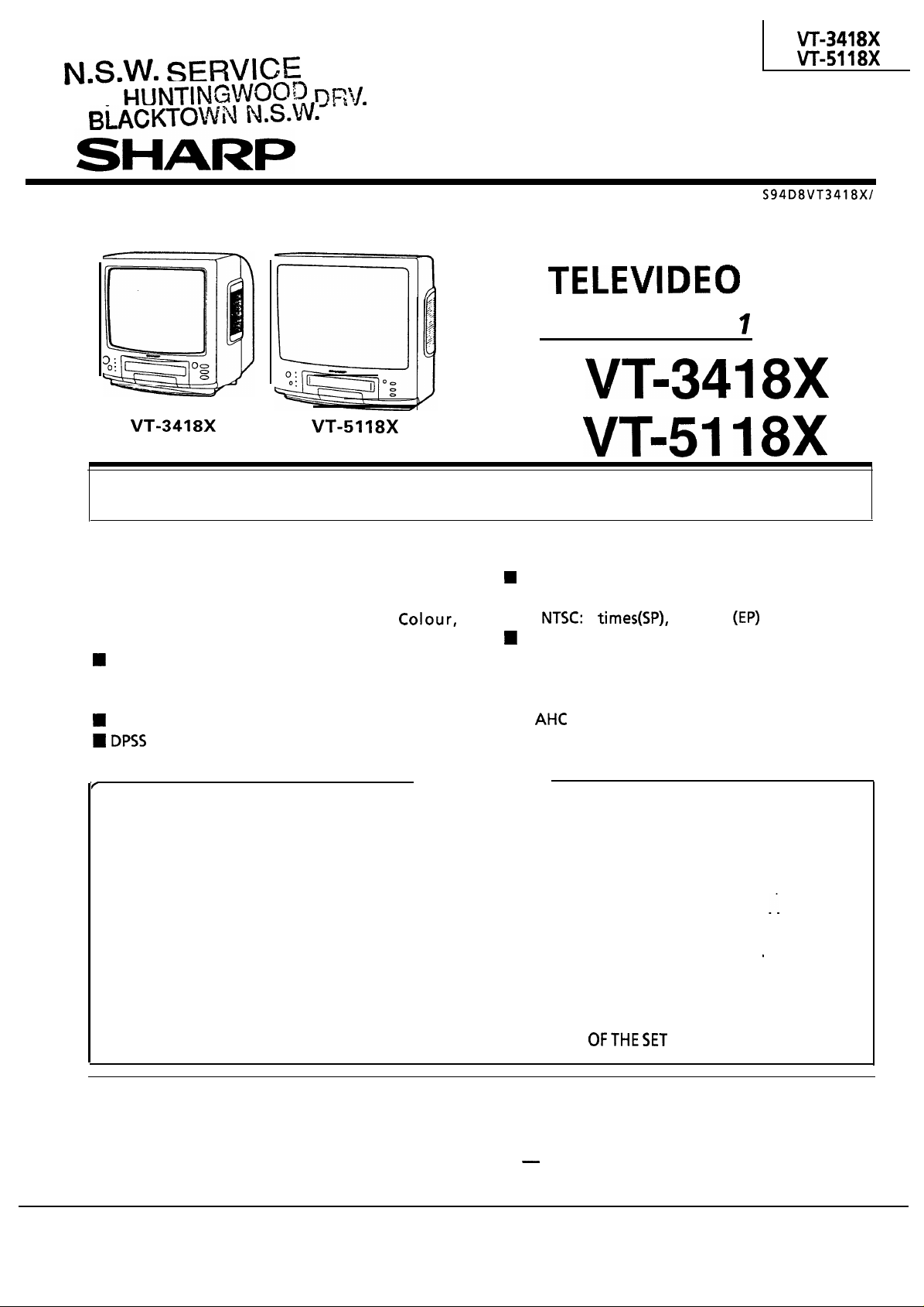
SERVICE MANUAL
TV/VCR COMBINATION
Chassis No. VP-
In the interests of user-safety (Required by safety regulations in some countries ) the set should be
restored to its original condition and only parts identical to those specified should be used.
18X
MODELS
18X
FEATURE
n Full Auto Search Tuning System
n
On Screen Digital Channel/Sound Level/
Tuning Display, Control (Contrast,
Brightness, Tint, P-Tone) Symbol and Level
Blue Back Off Timer
n
40 Key, Wireless Remote Control Unit
n Channel Skip
Dew Warning Indicator
(Digital Program Search System)
.
SPECIFICATIONS
l
IMPORTANT SERVICE NOTES
l
LOCATION OF USER’S CONTROL
.
DISASSEMBLY AND REASSEMBLY
. ADJUSTMENT OF THE
TV ELECTRICAL CIRCUITRY
.
FUNCTION OF MAJOR MECHANICAL PARTS
. ADJUSTMENT, REPLACEMENTAND
ASSEMBLY OF MECHANICAL UNITS
. ADJUSTMENT OF THE
VCR ELECTRICAL CIRCUITRY
. TROUBLESHOOTING
........................
.............
.........
........
...........
.........
...................
High Speed Video Search System
l
PAUSECAM: 7 times
l
Quick Start Playback with Full Loading System
n
Still/Slow Function with Noiseless Frame Still
n
n
n
5
Digital Automatic Tracking Control
Automatic Playback Function
(Automatic Head Cleaning System)
15 times
CONTENTS
Page Page
l
2
3
4
7
8
14
..
16
41
47
OVERALL SCHEMATIC DIAGRAM
l
CHASSIS LAYOUT OF TV SECTION
l
BLOCK DIAGRAM OF TV SECTION
.
DESCRIPTION OF TV SECTION
SCHEMATIC DIAGRAM
.
CHASSIS LAYOUT OF VCR SECTION
.
BLOCK DIAGRAM OF VCR SECTION
. DESCRIPTION OF VCR SECTION
SCHEMATIC DIAGRAM
. PRINTED WIRING BOARD ASSEMBLIES . .
.
REPLACEMENT PARTS LIST
.
PACKING OFTHESET
.................
........
.......
.......
.......
.............
............
.....
......
.....
65
69
73
82
99
101
111
119
129
167
WARNING
The chassis in this receiver is partially hot. Use an isolation transformer between the line cord plug and
power receptacle, when servicing this chassis.
To prevent electric shock, do not remove cover. No user
qualified service personnel.
serviceable parts inside. Refer servicing to
SHARP CORPORATION
Page 2
n
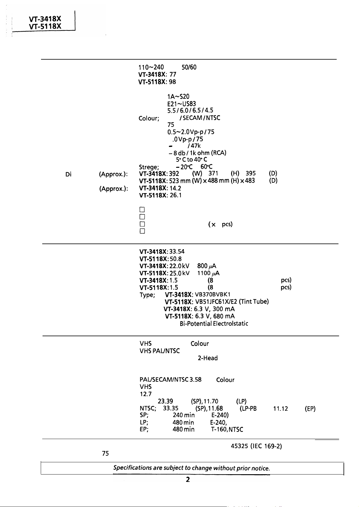
OUTLINE OF THE PRODUCT
Power Source:
Power Consumption:
Receiving Broadcast Standard:
Receiving Channel:
Receiving System:
Antenna Input Impedance:
Video Signal:
Audio Signal:
Temperature:
mentions
Weight (Approx.):
Cabinet Material:
Accessories:
n
TV SECTION
Viewing Area:
Picture Power:
Speaker Output:
Picture Tube:
n
VCR SECTION
SPECIFICATIONS
PAL System B/G, I, D/K, M
VHF;
UHF;
Sound;
VHF/UHF;
Input;
output;
Input;
output;
Operation;
Plastic
Operation Manual
Infrared Remote Control Unit
Dry Batteries, Type AA
Guarantee Card
Heater;
Focus;
V AC,
w
W
PAL
ohm Unbalanced (DIN)
1
8 d b
W at Max.
W at Max.
High
Hz
MHz
mm
kg
kg
cm Diagonal Measurement
Vp-p ohm (RCA)
75 ohm (RCA)
ohm (RCA)
to
x
cm Diagonal Measurement
at
at
cm Round Dynamic x 2
cm Round Dynamic x 2
mm
2
Beam Current
Beam Current
x
U-S (Tint Tube)
(TintTube)
mA
mA
mm
mm
Outline:
Format:
Video Recording System :
Luminance: FM Recording
Chrominance: Low Frequency Converted Direct Recording
Video Signal System: PAUSECAM/NTSC MHz
Cassette Tape:
Tape Width:
Tape Speed:
Recording/Playback Time:
Note: The antenna must correspond to the new standard DIN 45325
antenna with
ohm connector.
Video System
Rotary Slant Azimuth 2-Head Helical Scan System
Type Video Cassette Tape
mm
PAL;
Standard
mm/s
Max.
Max.
Max.
Video Cassette Recorder
mm/s
11.68 mm/s
(with
(with
(with
PAL only)
only)
only),
mm/s
for combined UHF
Page 3

IMPORTANT SERVICE NOTES
Maintenance and repair of this receiver should be done by
qualified service personnel only.
SERVICING OF HIGH VOLTAGE SYSTEM AND
PICTURE TUBE
When servicing the high voltage system,
connecting a
probe) between picture tube
k ohm Resistor in series with an insulated wire (such as a test
and
remove static charge from it by
anode lead. (AC line cord should
be disconnected from AC outlet.)
Picture tube in this receiver employs integral implosion protection.
Replace with tube of the same type number for continued safety.
Do not lift picture tube by the neck.
Handle the picture tube only when wearing shatterproof goggles and after discharging
the high voltage completely.
X-RAY
This receiver is designed so that any X-Ray radiation is kept to an absolute
minimum. Since certain malfunctions or servicing may produce potentially
hazardous radiation with prolonged exposure at close range, the following
precautions should be observed:
If there is a possibility that the high voltage fluctuates as a result of the repairs, never
forget to check for such high voltage after the work.
DO not substitute a picture tube with unauthorized types and/or brands
excess X-ray radiation.
When repairing the circuit, be sure not toincrease the high voltage to more
than
When repairing the circuit, be sure not to increase the high voltage to more
than
To keep the set in a normal operation, be sure to make it function on
been factory
To keep the set in a normal operation,
factory -Adjusted to the above-mentioned high voltage.
+
(at beam 0
(at beam 0
-Adjusted to the above-mentioned high voltage.
(at beam
for the set.
for the set.
(at beam
in the case of the set. The set has
be sure to make it function on
in the case of the set. The set has been
BEFORE RETURNING THE RECEIVER
Before returning the receiver to the user, perform the following safety
checks.
Inspect all lead dress to make certain that leads are not pinched or that hardware is not
lodged between the chassis and other metal parts in the receiver.
Inspect all protective devices such as non-metallic control knobs, insulating fishpapers,
cabinet backs, adjustment and compartment covers or shields, isolation resistorcapacity networks, mechanical insulators etc.
Page 4
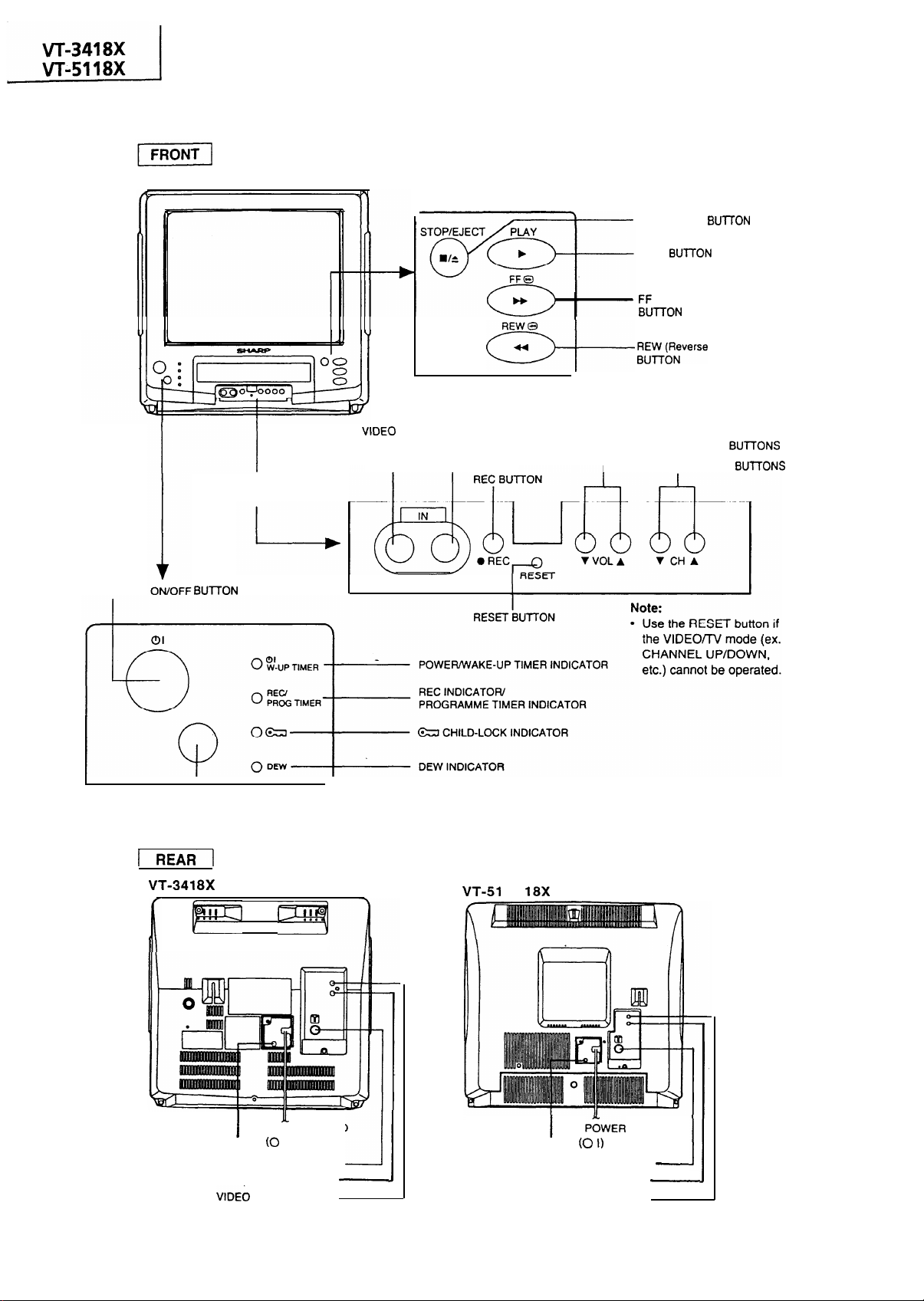
LOCATION OF USER’S CONTROL
STOP/EJECT BUlTON
PLAY BlJlTON
(Forward video search)
CONTROL PANEL
INSIDE THE COVER
POWER BUTTON
AUDIO INPUT JACK
I
VIDEO AUDIO
VOLUME UP/DOWN
I
CHANNEL UP/DOWN
r
video search)
I
SENSOR AREA FOR
REMOTE CONTROL
q
MAIN POWER SWITCH
ANTENNA IN TERMINAL
AUDIO OUT TERMINAL
OUT TERMINAL
I
. . .
POWER CORD
I)
MAIN POWER SWITCH
4
.
CORD
ANTENNA IN TERMINAL
AUDIO OUT TERMINAL
VIDEO OUT TERMINAL
Page 5
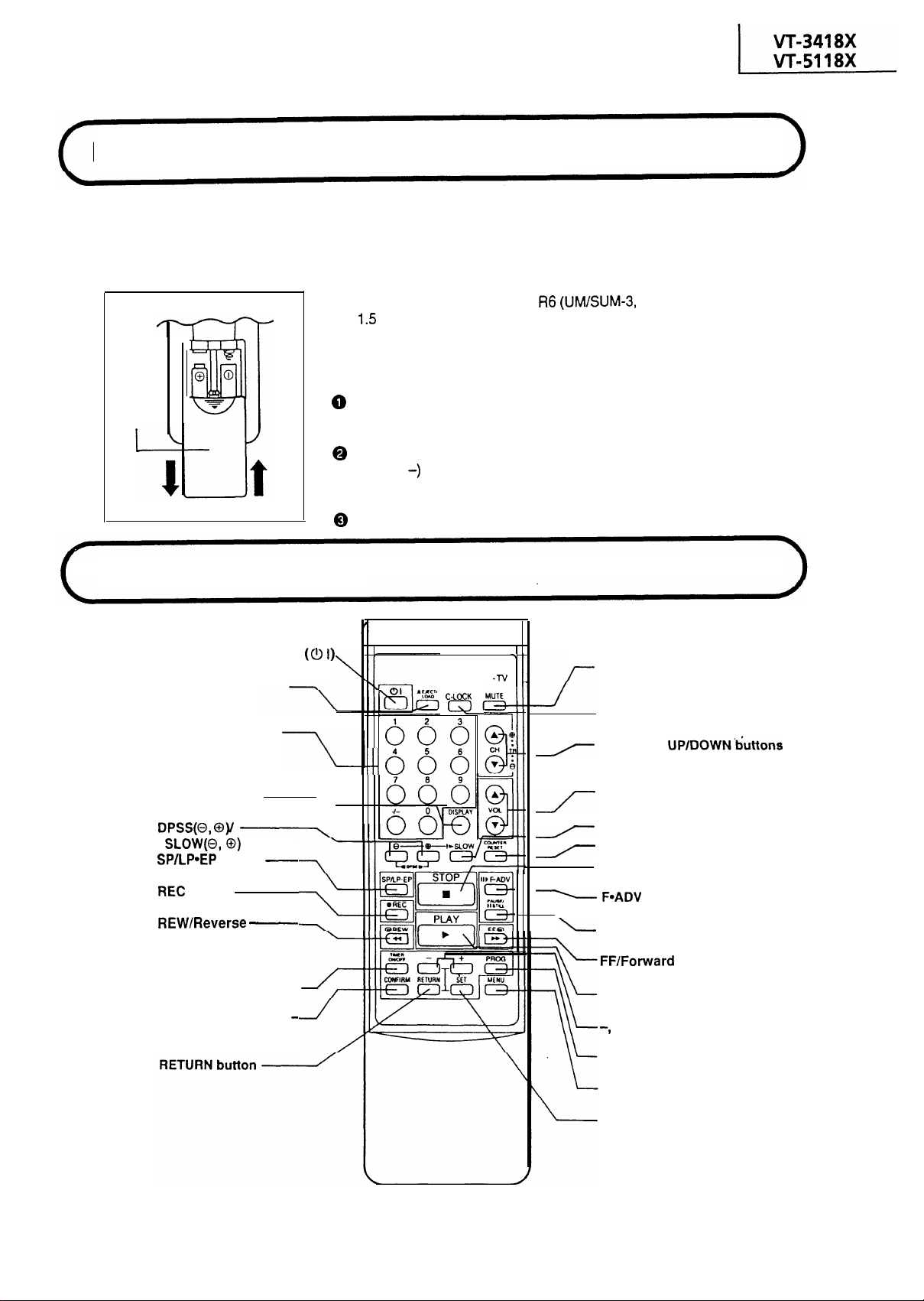
Remote Control Battery Installation
The remote control lets you operate this product at a distance. Just aim the front of the remote
control at the photoreceptor window situated on the front panel and press the appropriate
buttons.
Inserting the Batteries
The remote control operates on two
AA)
volt batteries (included). If the remote control
does not operate or fails to function normally due to
weak batteries, new batteries can be purchased at
electronics or camera stores.
(UM/SUM-3,
Battery
cover
Location
POWER ON/OFF button
EJECT/LOAD button
CHANNEL SELECT
buttons
DISPLAY button
button
of Controls
buttons
button
Open the battery cover. (Remove any old batteries that may be in the remote control.)
Insert new batteries and match their polarities
( + and
ment.
Replace the cover.
with the markings inside the compart-
SHARP
VIDEO
I
MUTE button
CHILD-LOCK button
CHANNEL UP/DOWN&&tons
VOLUME ADJUSTMENT
buttons
SLOW PLAYBACK button
COUNTER RESET button
STOP button
(TRACKING buttons)
button
Video Search button
TIMER ON/OFF button
CONFIRMING TIMER
PROGRAMME button
PAUSE/STILL button
Video Search button
PLAY button
+ buttons
PROGRAMME button
MENU button
SET button
5
Page 6
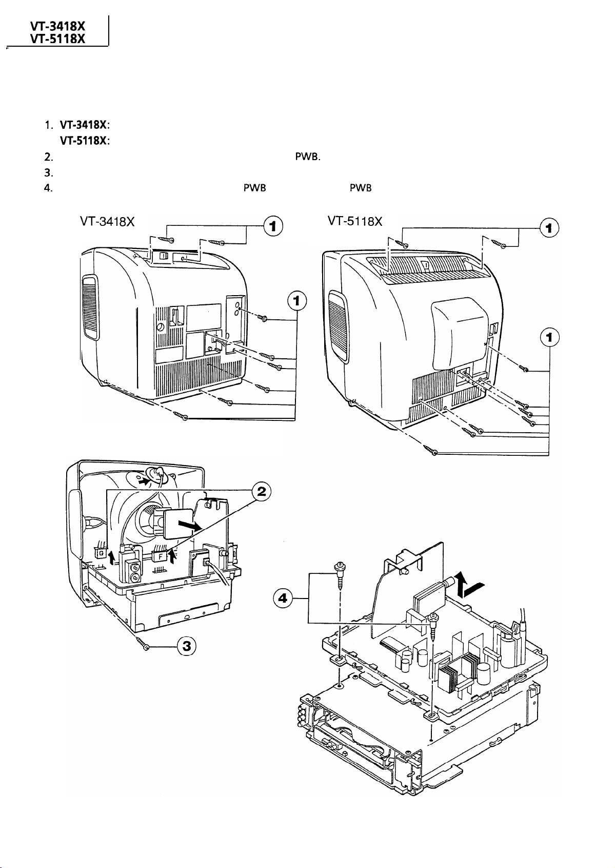
8X
n
TV SECTION
DISASSEMBLY AND REASSEMBLY
18X: Remove the nine screws off the rear cover.
Disconnect the F and G connectors from the main
Remove the screws off the video unit and take out the unit.
Remove the two screws from the main
Remove the eight screws off the rear cover.
and separate the
from the video unit
6
Page 7
n
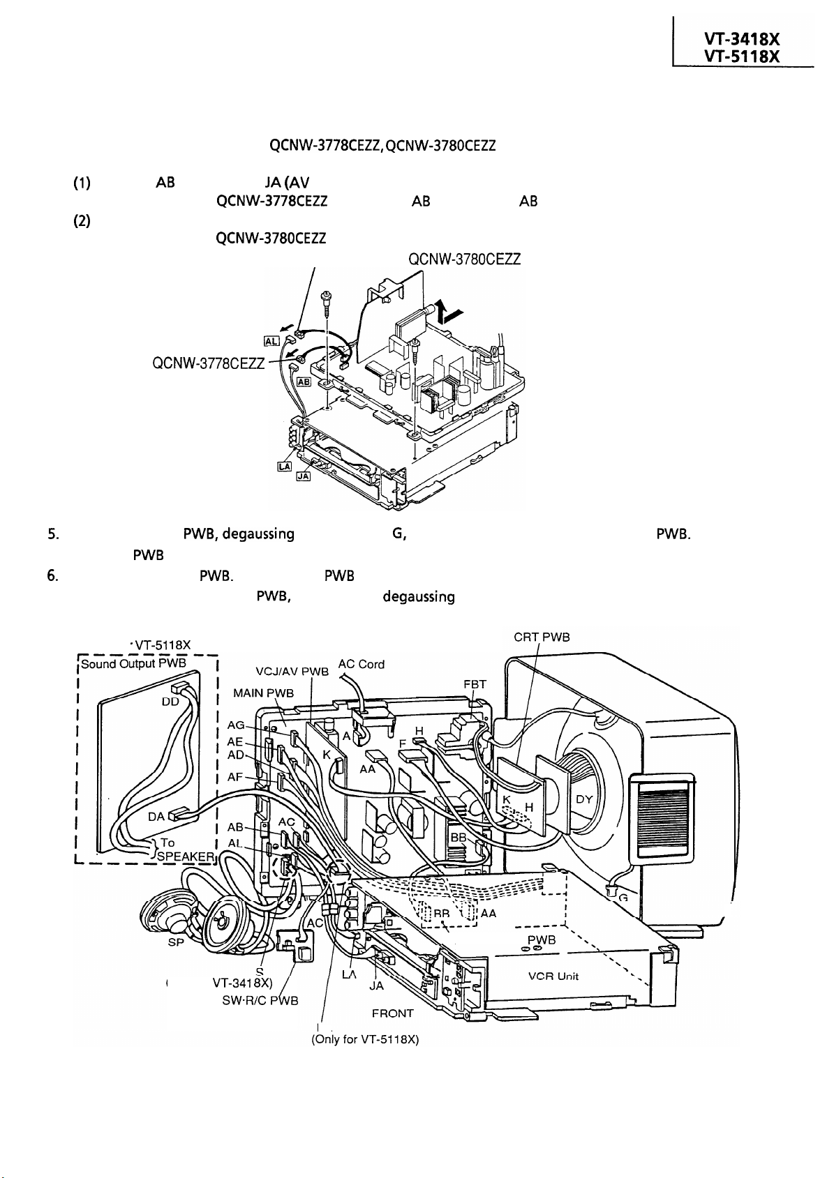
CONNECTIONS FOR SERVICING
Use the following extension cables in servicing the VCR unit taken out of the set.
Extension cables:
l
Connecting the extension cables
Between
Part codes
(TV unit) and
Connect the cable
jack):
between the
plug and the
socket.
Between AL (TV unit) and LA (LED unit):
Connect the cable
between the AL plug and the AL socket.
Extension cable: QCNW-3780CEZZ
Extension
cable: QCNW-3778CEZZ
Remove the CRT
the main
upright.
Reconnect the CRT
power switch remote control
VT-51 18X
Only for
Put the main
coil connector
and the VCR unit together as shown below. Keep the front
speakers and
and front power switch remote control
coil connector G off position.
Place
(Only for VT-341 8X)
Power
,
‘LINE FILTER PWB
PWB
DA
Page 8
8X
I
I
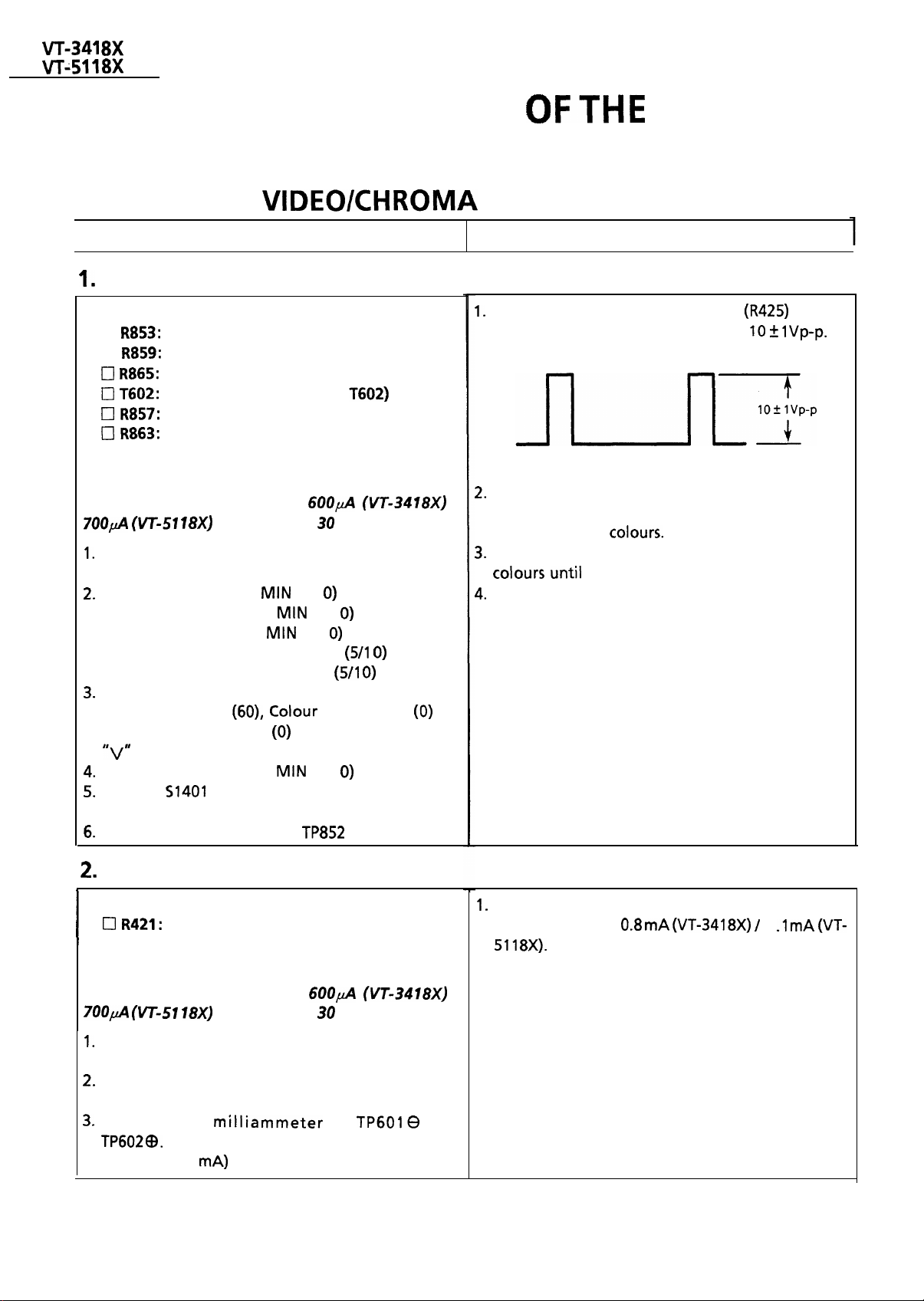
ADJUSTMENT
TV ELECTRICAL CIRCUITRY
ADJUSTMENT
I
Adjusting Conditions
CRT Cut-off Adjustment
Adjusting Point
Cl
Cl
Note:
Prior to this adjustment, warm up the unit with the
beam current of more than
Receive “MONOSCOPE PATTERN” signal with
pattern generator.
Set Red bias control at
Set Green bias control at
Set Blue bias control at
Set Green drive control at CENTER position.
Set Blue drive control at CENTER position.
Set the control at the “NORMAL” position that
Contrast is MAX
Brightness is CENTER
Set the Screen control at
Turn on
line position.
Connect the oscilloscope to
Red Bias control
Green Bias control
Blue Bias control
Green Drive control
Blue Drive control
keys.
for more than
(Service switch) at the horizontal
minutes.
(O/l
using control, “A” and
position.
(O/l
(O/l
(O/l
position.
position.
is CENTER
position.
(Red Cathode).
an
Adjusting Procedures
Adjust the Sub-Brightness control
the blanking pulse on oscilloscope is
Slowly turn the Screen control clockwise and stop
I
it where the horizontal raster appears slightly, in
one of the three
Carefully adjust the Bias controls of the other two
untii the horizontal raster becomes white.
Turn the Screen control counterclockwise until
the horizontal raster disappears, and stop it.
so that
Sub-Contrast Adjustment
Adjusting Point
Sub-Contrast control
Note:
Prior to this adjustment, warm up the unit with the
beam current of more than
Receive “MONOSCOPE PATTERN” signal with
pattern generator.
Set the Contrast and Brightness controls at MAX
position.
Connect DC
(Full scale: 3
for more than 30 minutes.
to
and
8
Adjust Sub-Contrast control so that the beam
current becomes
I
mA
1
mA
Page 9
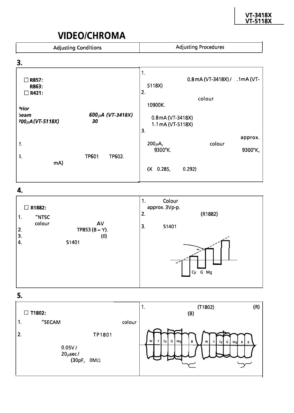
ADJUSTMENT (Continued)
White Balance and Back Ground Adjustment
Adjusting Point
Green Drive control
Cl
Blue Drive control
Sub-Contrast control
Vote:
to this adjustment, warm up the unit with the
current of more than
for more than 30 minutes.
(VT-3418X) I
I. Receive “MONOSCOPE PATTERN” signal with
pattern generator.
Set the Contrast and Brightness controls at MAX
position.
Connect beam ammeter to
and
(Full scale: 3 mA)
Sub-Tint Adjustment
Adjusting Point
Feed
with
Connect oscilloscope to
Set the Tint control at the CENTER
Set Service switch
to cut off the Y-signal.
Sub-Tint control
COLOUR BAR” signal to video in jack
bar generator at the
mode.
position.
at the Video Cut position
Adjust the Sub-Contrast control so that the beam
current becomes
mA
1
mA
Adjust the Green Drive control and Blue Drive
control so that the colour temperature is at
l
High beam:
mA
mA(VT-5118X)
Adjust the Contrast control and Brightness
control so that the beam current is
at
and check that the
If the temperature is not at
temperature is
go back to “CRT CUT-OFF ADJUSTMENT” and
repeat the adjustment.
Y = 0.292)
Adjust
control key to obtain the output of
Adjust Sub-Tint control
so that the output
waveform is as shown in figure below.
Return
Same
to CENTER (normal position).
level
Bell Filter Adjustment
Adjusting Point
Receive
bar generator.
Connect oscilloscope to TP1801 with the
following settings.
l
Range:
l
Sweep Time:
l
Probe:
Bell Filter
COLOUR BAR” signal with colour
div. AC
div.
l/l 0
1
or more)
B-Y
.
W Y
Adjust the Bell Filter
output and blue
amplitude.
R
9
R B
so that the red
output will have the same
Same amplitude
Page 10
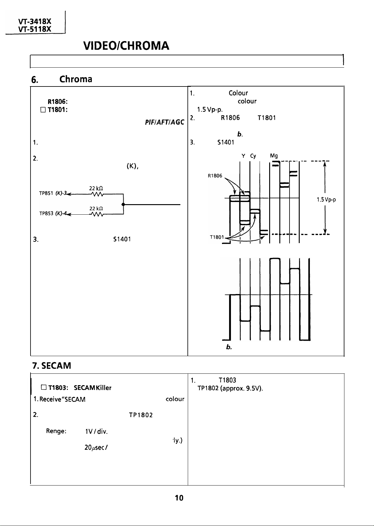
ADJUSTMENT (Continued)
Adjusting Conditions
PAL
Adjusting Point
Cl
Note: Before this adjustment, the
adjustment must have been completed.
Receive “PAL COLOUR BAR” signal with pattern
generator.
Connect the following resistance matrix to pins 3
and 4 of the connector
oscilloscope is connected.
Set the Service switch
position to cut off the Y-signal.
Adjustment
1 H Delay Amp. control
1 H Delay Phase control
to which an
To oscilloscope
Resistance Matrix
at the Video Cut
I
Adjust the
waveform of
vp-p.
Adjust
waveform shown in Fig. a is corrected to that
shown in Fig.
Return
Adjusting Procedures
control key so that the output
difference signal becomes
and
to CENTER (normal position).
W
G Mg R B
so that the output
1
Figure a. Waveform before the adjustment
r
Adjusting Point
bar generator.
Connect oscilloscope to
following settings.
l
l
Sweep Time:
Killer Adjustment
COLOUR BAR” signal with
DC
(Adjust vertical position proper
div.
control
with the
Figure
Adjust
Waveform after the adjustment
to obtain maximum DC voltage at
Page 11
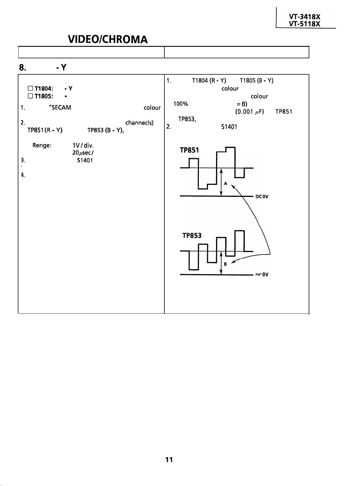
ADJUSTMENT (Continued)
Adjusting Conditions Adjusting Procedures
R -Y/B
Adjusting Point
Receive “SECAM COLOUR BAR” signal with colour
bar generator.
Connect the oscilloscope (with two
on the CRT Socket Unit of the set.
l
l
Sweep Time:
Set service switch
to cut-off the Y-signal.
Set both the Contrast and Brightness controls to
their maximum postions.
Discriminator Adjustment
R Discriminator
B
Y Discriminator
to
and the
DC
div.
at the Video Cut position
both located
Adjust
output level with
will be the same as that with
of saturation. (A
* Connect capacitor (0.001
Set service switch
thus to prevent noise interference.
and
control set at minimum
to the canter position.
so that DC
control set at
to
and
Same
B
DC
DC output level
Page 12
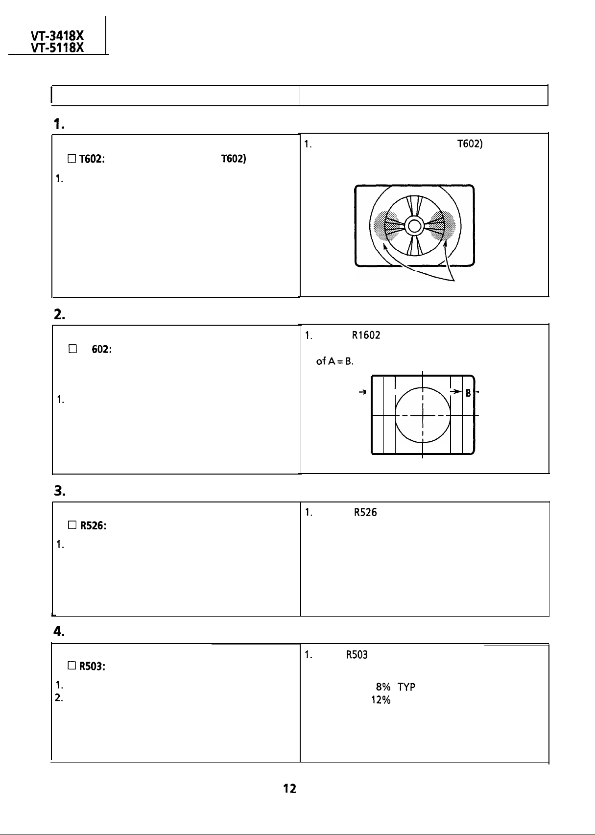
DEFLECTION LOOP ADJUSTMENT
Adjusting Conditions
Focus Adjustment
Adjusting Point
Receive “MONOSCOPE PATTERN” signal.
2 Set the Brightness and Contrast controls at
NORMAL position.
Horizontal Center Adjustment
Adjusting Point
RI
Note: This adjustment should be performed after
the purity and convergence adjustments.
Receive “MONOSCOPE PATTERN” signal.
Adjusting Procedures
l
During the adjustment, keep the unit facing the east.
Adjust Focus control (a part of
focus at the central area of CRT.
l
During the adjustment, keep the unit facing the east.
Adjust
picture is at the position which gives the relation
so that the horizontal center of
A-
l
to have best
Adjust point
4
Vertical Linearity Adjustment
Adjusting Point
Vertical Linearity control
Receive “MONOSCOPE PATTERN” signal.
Vertical Size Adjustment
Adjusting Point
Vertical Size control
Receive “MONOSCOPE PATTERN” signal.
Set the Brightness and Contrast controls at MAX
position.
I
l
During the adjustment, keep the unit facing the east.
Adjust
picture is at best point.
l
During the adjustment, keep the unit facing the east.
Adjust
the same size as horizontal size.
. V-SIZE
so that the vertical linearity of
so that the vertical size of picture is at
Page 13
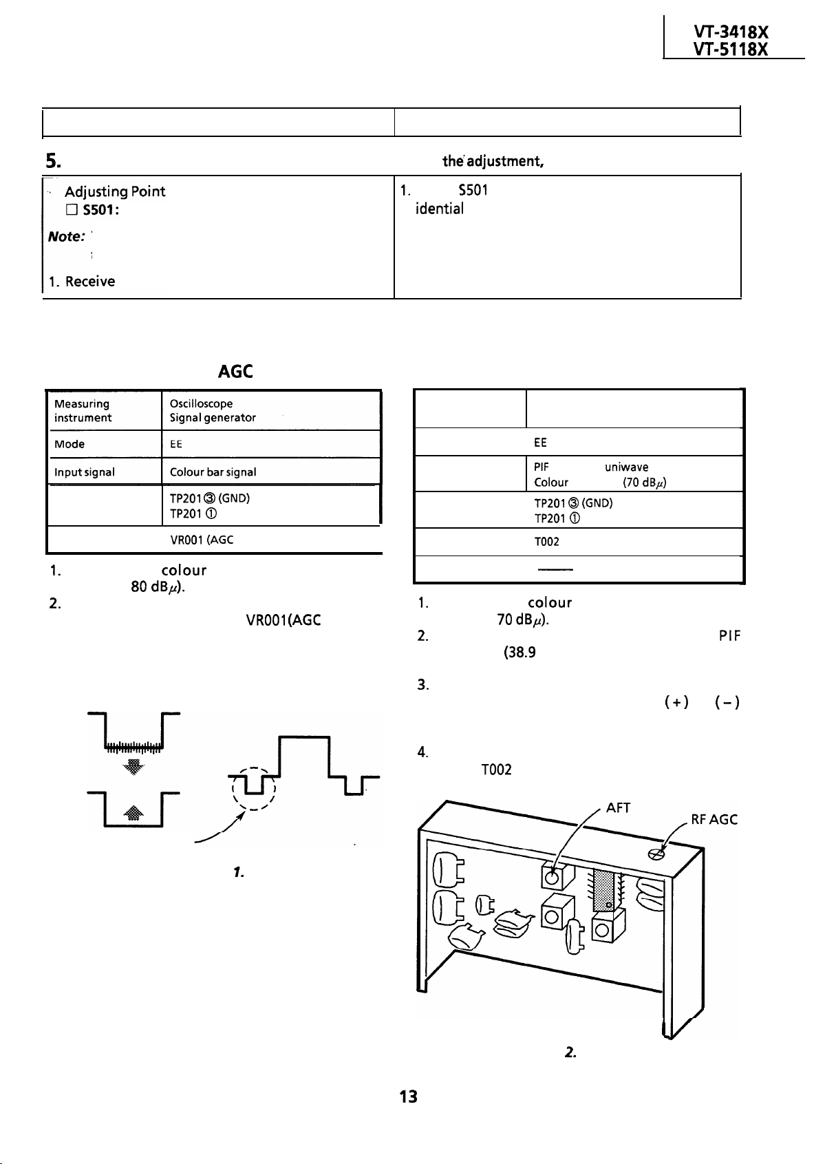
DEFLECTION LOOP ADJUSTMENT (Continued)
Adjusting Conditions
Vertical Centering Adjustment
Vertical Center Adjust switch
This adjustment should be performed after
the purity and convergence adjustments.
“MONOSCOPE PATTERN” signal.
ADJUSTMENT OF THE IF CIRCUIT
Adjustment of the RF
Test point
Adjusting point
I
(Video Output)
control)
Adjusting Procedures
l
During
Adjust
so that the picture’s vertical center is
Adjustment of the AFT
Measuring
instrument Signal generator
Mode
Input signal
Test point
I
Adjusting point
keep the unit facing the east.
Oscilloscope
I
frequency
dBp)
I
I
(Video Output)
(AFT coil)
Receive the
strength:
bar signal (input field
Observe the video output terminal waveform
on the oscilloscope. Adjust
control)
in the IF pack until the noise disappears from
the oscilloscope screen and the waveform
nearly comes into sync.
Just before shrinking
Figure
Specification
I
Receive the colour bar signal (input field
strength:
Using the signal generator, feed the
frequency
MHz) signal (sinewave) to the
tuner IF output terminal.
Set the tuning switch to the VHF or UHF
position. Keep the tuning button
or
depressed until the beating on the oscilloscope
screen be minimum.
Set the tuning switch on the normal position.
Adjust
(AFT coil) so that beating on the
oscilloscope screen be minimum.
Figure
IF Pack
Page 14
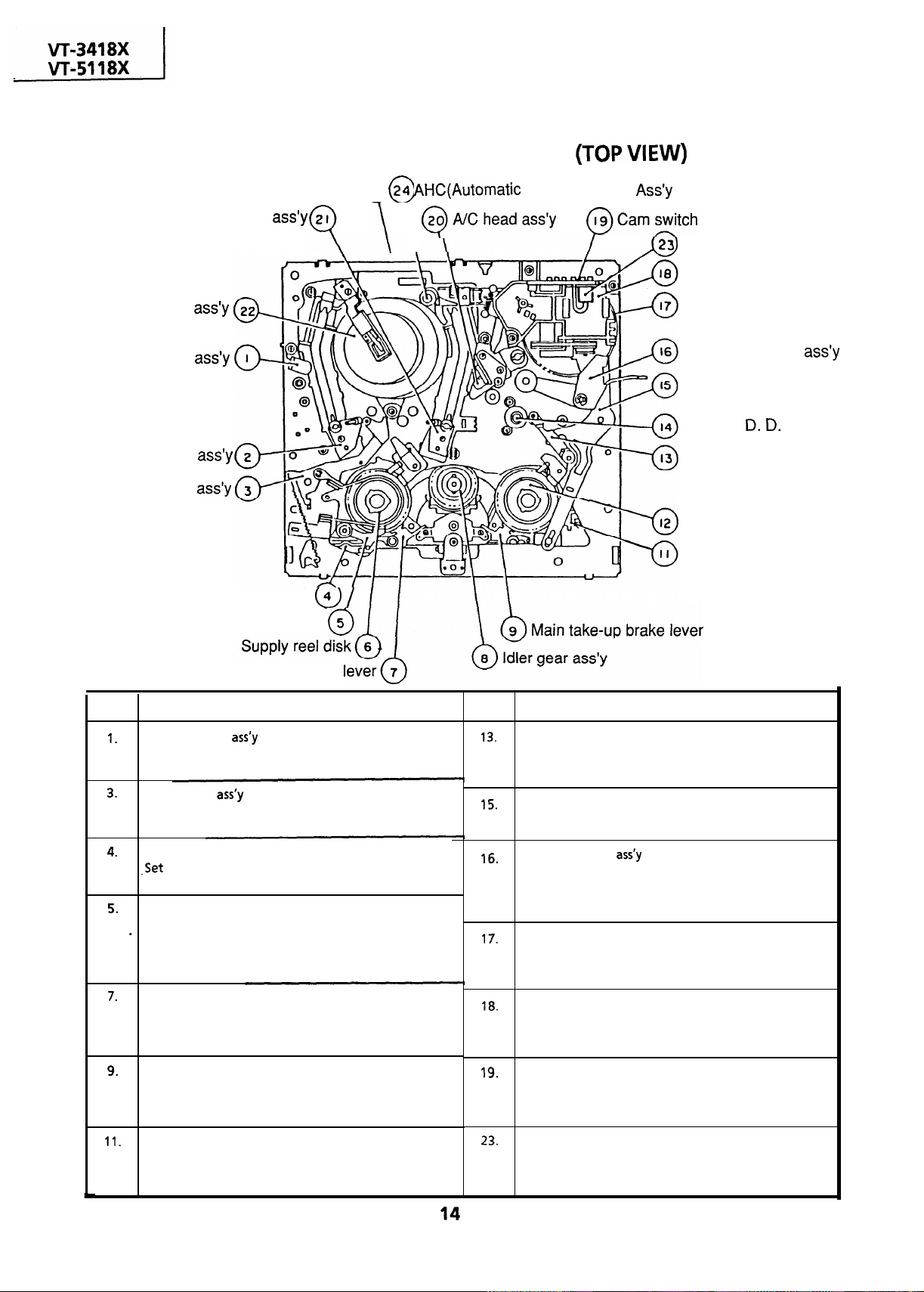
FUNCTION OF MAJOR
MECHANICAL PARTS
Take-up pole
Drum
Full erase head
Supply pole base
Tension arm
base
I
Brake shifter
Back tension lever
Head Cleaner)
Dew sensor
Loading motor
Master cam
Pinch roller lever
Relay shifter lever
Capstan
motor
Reverse guide
Take-up reel disk
Video
search brake
lever
Main supply brake
No.
Full erase head
Erase the whole records on the tape in the recording
mode.
Tension arm
Detects the tension of tape while running, and brakes
the supply reel disk via the tension band.
Brake shifter
the modes such as stop and playback.
Back tension lever
Brakes the supply reel disk to a certain degree to .
prevent tape slackening during “half-loading”,
“loading” and “shifting from playback to video search
rewind”.
Main supply brake lever
Brakes the supply reel disk to prevent tape slackening
when the unit is stopped in fast forward or rewind
mode.
Main take-up brake lever
Brakes the take-up reel disk to prevent tape slackening Rotates synchronously with the master cam, and
when the unit is stopped in fast forward or rewind detects the position of each mode by means of the
mode.
Function
No.
Reverse guide
Pulls out the tape in the video search rewind mode,
and controls the tape drive train height with the upper
and lower guides.
Relay shifter lever
Transmits the operation of the master cam to the
brake shifter, and operates the reverse guide.
Pinch roller lever
Press-fits the tape to the capstan during tape running.
The right protrusion switches the clutch of the cassette
housing control assembly in “tape eject”, and makes
the mechanism eject the tape.
Master cam
Turns clockwise during loading, and counterclockwise
during unloading, and moves the shifter or the like in
accordance with each mode.
Loading motor
A motive power which drives the mechanism. It
transmits the power to the master cam and cassette
housing control assembly via the belt.
Cam switch
internal switch.
Function
Video search brake lever
It is in contact with the take-up reel disk normally, and
brakes it to a certain degree. It applies larger brake in unit. This element is activated, when it senses
the video search rewind mode.
Dew sensor
An element which detects condensation inside the
condensation, to interrupt the mechanism.
Page 15
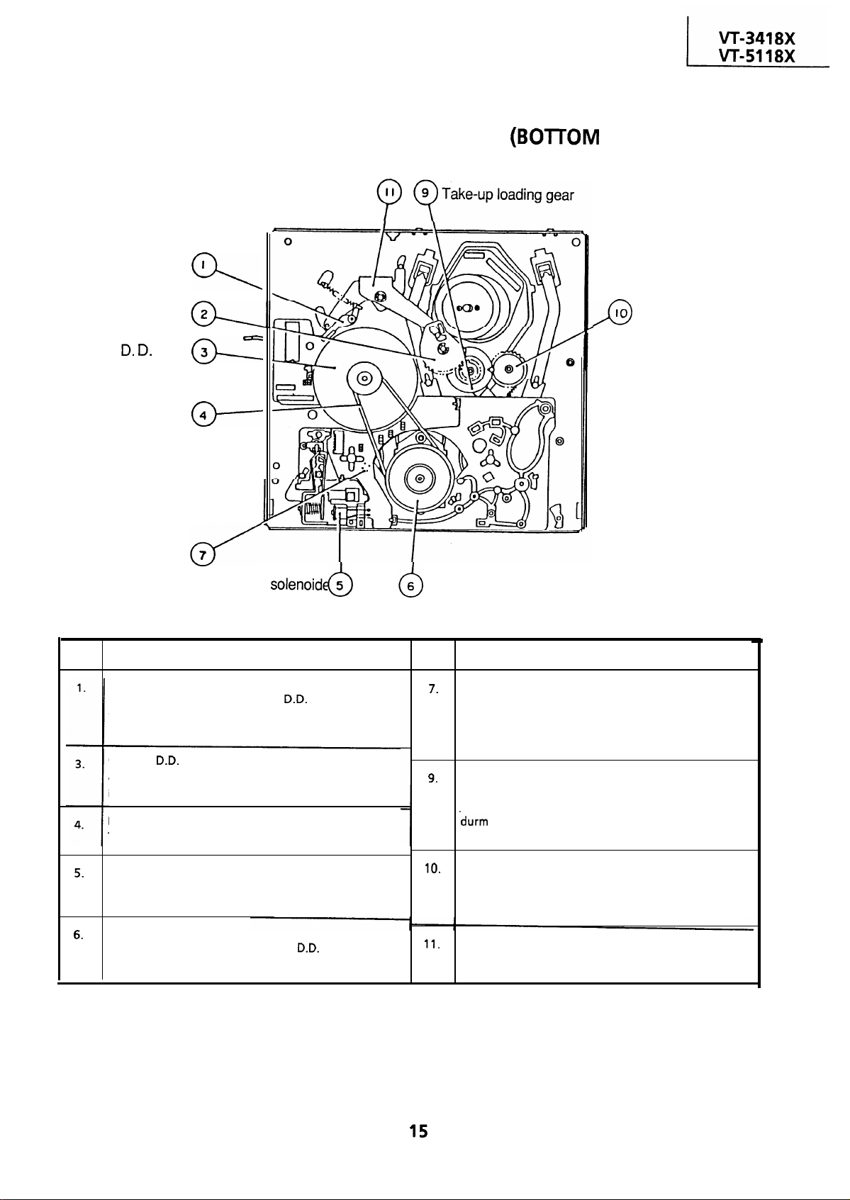
FUNCTION OF MAJOR
Slow brake lever
Loading relay gear
Capstan
motor
Reel belt
MECHANICAL PARTS
Relay gear drive lever
I
VIEW)
IO
Supply loading gear
Reel sensor
Brake
No.
Slow brake lever
Gets in contact with the capstan
the master cam in the slow still mode, and brakes it to a
certain degree.
Capstan
A motive power which runs the tape. It transmits the
power via the reel belt.
Reel belt
Transmits the power to run the tape to the reel pulley.
Brake solenoid
Adsorbs and holds the brake shifter in the fast forward
and rewind modes, and releases it in the stop mode.
Reel pulley
Transmits the power of the capstan
reel disk via the reel idler.
motor
Function
motor linking to
5
motor to the
Reel pulley
No.
Reel sensor
An element which sheds the light onto the reflection
plate affixed to the bottom side of the reel disk, and
detects the rotation of the reel disk through receiving
the reflected light.
Take-up loading gear
Shifts the take-up pole base and guide roller via the
loading relay gear, and applies the tape around the
assembly, as well as transmits the power to the
supply loading gear.
Supply loading gear
.
Shifts the supply pole base and guide roller via the
take-up loading gear, and applies the tape around the
drum assembly.
Relay gear drive lever
Transmits the movement of the master cam to the
take-up loading gear via the loading relay gear.
Function
Page 16
ADJUSTMENT, REPLACEMENTAND
ASSEMBLY OF MECHANICAL UNITS
Here we will describe a relatively simple service
work in the field, not referring to the more
complicated repairs which would require the use of
special equipment and tools (drum assembly
We are sure that the easy-to-handle tools listed
below would be more than handy for periodical
maintenance to keep the machine in its original
working condition.
replacement, for example).
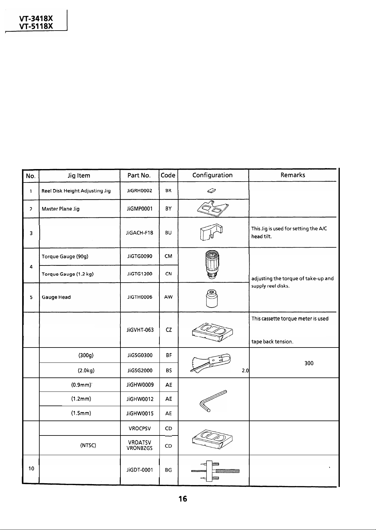
TOOLS NECESSARY FOR ADJUSTING THE MECHANICAL UNITS
The following tools are required for proper service and satisfactory repair.
These Jigs are used for checking and
adjusting the reel disk height
A/C Head Tilt Adjusting Jig
6
Cassette Torque Meter
Tension Gauge (3009) .
7
Tension Gauge
Hex Wrench (0.9mm)’
Hex Wrench (1.2mm)
8
Hex Wrench (1.5mm)
Alignment Tape (PAL)
9
Alignment Tape
.
These Jigs are used for checking and
for checking and adjusting the
torque of take-up for measuring
There are two gauges used for the
tension measurements, 300 g and
kg.
These Jigs are used for loosening or
tightening special hexagon type
screws.
This tape is especially used for
electrical fine adjustment.
Drum Replacing Jig
This is used for replacement of the
VCR’s upper drum.
Page 17
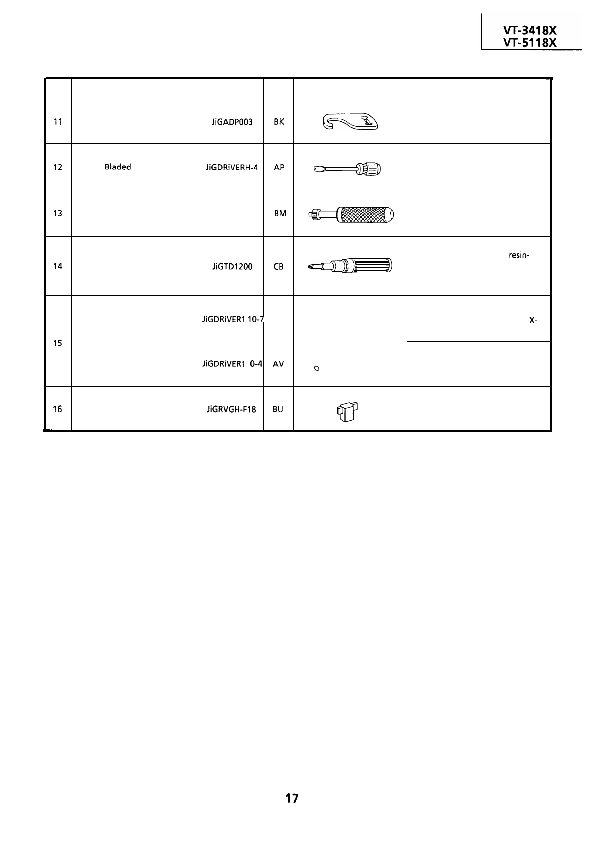
No.
Tension Gauge Adapter
Jig Item
Part No.
Code
Configuration
Remarks
This Jig is used with the tension
gauge. Rotary transformer
clearance adjusting jig.
Special Bladed Screwdriver
Tension Band and Plate
Adjusting Jig
Torque Driver JiGTDl200
Box Driver
Reverse Guide Height Adjusting
Jig
JiGDRiVER-
AS
1
This screwdriver is used for adjusting
the guide roller height.
This Jig is used for adjusting the
tension band and tension plate.
This is used to screw down resin-
made parts: the specified torque is 5
kg-
This Jig is used for height
adjustment of the A/C head and X-
position.
This Jig is used for height
&@
adjustment of the retaining guide.
This Jig is used for height
adjustment of the reverse guide.
Page 18
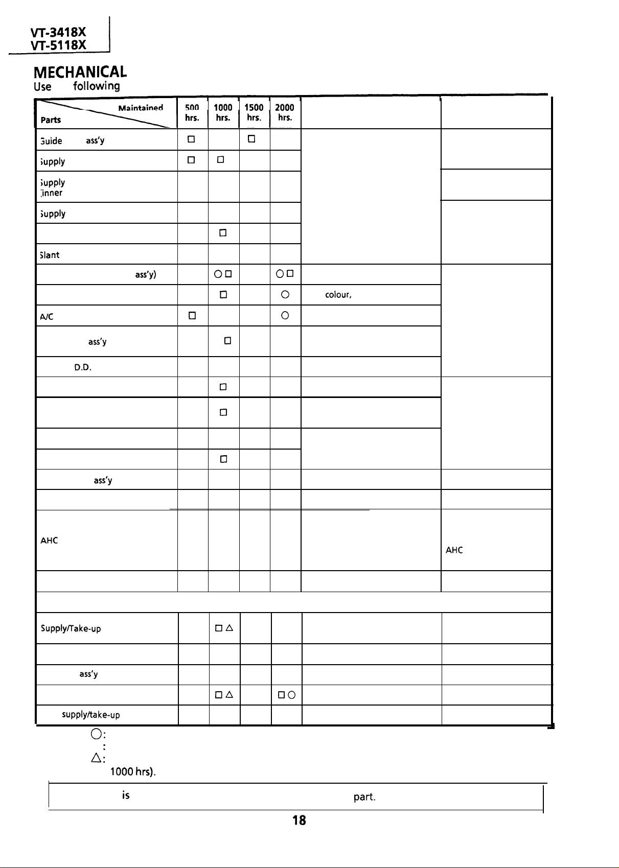
the
table as a guide to maintain the mechanical parts in good operating condition.
roller
impedance roller
impedance roller
hole and shaft)
impedance roller flange
Retaining guide
pole
Video head (upper drum
Full-erase head
head
Lower drum
Capstan
Pinch roller
Motor
q
q 0
0
q
q q q q
q
q q
q q q 0
q
q
q
q
q q
cl
q 0
q cl q 0
q
q 0
Possible symptom encountered Remarks
Abnormal rotation or
significant vibration
requires replacement.
q
Lateral noises
. Head occasionally blocked
Poor S/N ratio, no color
Poor colour, beating
Sound too small or distorted
Poor flatness of the envelope with
alignment tape
No tape running, uneven color
No tape running, tape slack
Clean with pure high
quality isopropyl alcohol.
Clean tape contact part
with the specified cleaning
liquid.
Clean tape contact area
with the specified cleaning
liquid.
Reel belt
Loading belt
Cassette loading belt
Tension band
Loading Motor 0
(Automatic Head Cleaner)
Reel block*
* See the table below for servicing the reel block parts.
q
0 0
A 0 No tape running, tape slack
Video search brake lever
Idler gear
Reel Pulley
No tape running, tape slack, no
0
fast forward/rewind motion
0
Cassette not loaded or unloaded
Lateral image swing
0
Cassette not loaded or unloaded
See the chart below.
0
No tape running
0
Clean rubber and rubber
contact area with the
specified cleaning liquid.
Replace the roller of the
cleaner when it wears
down. Just change the
roller assembly for
new one.
Clean with pure high
quality isopropyl alcohol.
Main
NOTE:
If the reading
brake levers
0 Tape slack
Part replacement.
Cl
Cleaning (For cleaning, use a lint-free cloth dampened with pure isopropyl alcohol).
Oil refilling (The indicated point should be lubricated with high quality spindle oil every
out of the specified value, clean or replace the
Page 19
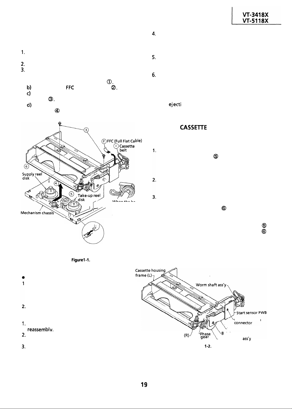
REMOVAL AND REASSEMBLY OF
CASSETTE HOUSING CONTROL ASSEMBLY
l
Removal
Set the cassette ejected condition in the cassette
eject mode.
Unplug the recorder from the main source.
Follow the procedures below in the specified
order.
a) Remove the cassette loading belt
Disconnect the
Remove the cassette housing installation
screws
Slide and pull out the cassette housing control
assembly @ upward.
(Full Flat Cable)
loading Note the
When the
detached, tuck it
as in the figure so
that it is kept free
from grease.
belt is
In removal and reassembly, take care not to hit
the cassette housing control assembly or tools
against the guide pin, drum, or the like
thereabout.
Place the unit in the eject mode in removal or
reassembly of the cassette housing control
assembly.
Load the cassette once onto the cassette housing
control assembly after reassembly. (If the
cassette housing control assembly normally
operates after this, the phases of mechanism and
the cassette controller are accurately adjusted
after
on.)
MECHANICAL OPERATION CHECK
WITHOUT
When power is on, the general operations of the
mechanism can be checked without a cassette.
following points.
Check video search rewind and rewind, rotating
the take-up reel disk
normal or reverse direction). If it is not rotated,
the reel sensor works to shift the mechanism to
the eject mode.
When the stop button is pressed, the mechanism
does not stop at a normal stop position. It shifts
to the eject mode and stops.
When the stop button is pressed in the playback,
video search rewind, and video search forward
modes, the supply reel disk
for several seconds for elimination of tape slack
in the course of shifting to the eject mode. In
such a case, rotate the take-up reel disk
somewhat by hand, and the supply reel disk
stops, which can reduce the working time.
by hand (in either
keeps on rotating
insert the tab of
the Cassette housing
control assembly to
the mechanism chassis.
Reassembly
.
Before installation of the cassette housing
control assembly, place the unit in the stop mode
with the power on, then unplug the power cord.
(The main body is placed in the eject mode.)
Follow the procedures for removal in the reverse
order.
Notes:
Be sure to unplug the power cord in removal and
Keep the cassette loading belt free from grease.
In case of its adhesion, clean the belt.
In using a magnet screw driver, be sure to keep it
away from the A/C head, FE (Full Erase) head, or
the drum.
REPLACEMENT OF WORM WHEEL
ASSEMBLY
Cassette housing frame
Figure
Worm wheel
Cassette switch
Worm bracket
tight screw
Page 20
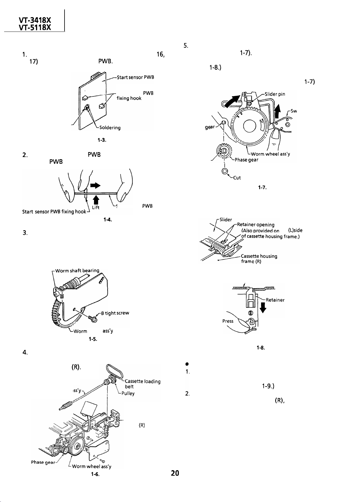
18X
l
Removal
Unsolder the cassette switch connectors (No.
from the start sensor
Start sensor
Cassette switch
connector
Figure
Lift the start sensor
sensor
fixing hooks inward.
pressing the two start
Start sensor
Place the slider pin just above the worm wheel
assembly (Figure l-7). (The retainer of the slider
is locked at two positions. So unlock it as in the
Figure
Pull out the worm wheel assembly toward you
6
pressing the switch lever upward. (Figure
itch lever
Phase
shaft
Tally mark
washer
Figure
Figure
Unscrew one B tight screw to detach the worm
bracket.
Note:
The worm shaft bearing can easily come-out of
position. So be careful not to lose it.
-Worm bracket
wheel
Figure
Remove the worm shaft assembly, pulley, and
cassette loading belt all from the cassette
housing frame
Worm shaft a
Cassette housing
frame
the
/-Slider
Cassette housing frame
(R)/(L) side
Figure
Reassembly
Turn the phase gear clockwise until the slider
comes to a halt in the cassette insertion
direction. (See the Figure
Insert the set up worm wheel gear assembly into
the cassette housing frame
matching the
mark on the phase gear with the mark on the
worm wheel gear. Detach the cut washer on the
phase gear assembly and the phase gear for
easier installation of worm wheel assembly.
Note:
Make sure that the slider pin is in the groove of
the drive gear arm.
Figure
Page 21
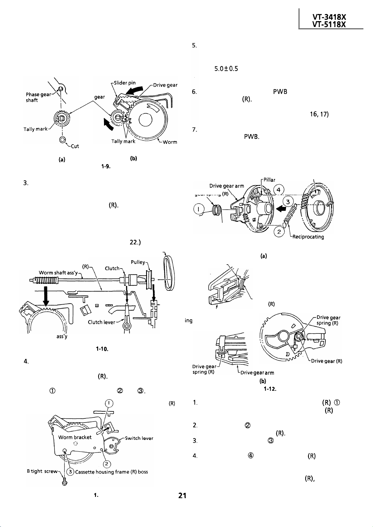
Phase
washer
Figure
wheel
Install the pulley and the cassette loading belt on
the worm shaft assembly. Couple the clutch to
the clutch lever. And mount them together in
the cassette housing frame
Note:
Keep in mind that the clutch switching lever
should be in the correct position.
The
mechanism might malfunction if the lever is
slightly out of position. (See page
Cassette loading belt
Tighten one B tight screw.
Note:
Do not over-tighten the B tight screw (no more
than
kg-cm), because the lower threads
of the screw hole at the resin-made boss can be
arm
broken.
Place the start sensor
housing frame
Note:
Check that the switch connectors (No. are
in the cassette switch mounting hole.
Finally resolder the cassette switch connector to
the start sensor
REASSEMBLY OF DRIVE GEAR
Drive gear spring
on the cassette
Worm wheel
square hole
Cassette housing frame
-Cassette
housing
frame(R)
shaft bear
Worm wheel
Figure
Attach the worm bracket to the worm shaft
assembly. Place them onto the boss on the
cassette housing frame
Note:
Insert
before screwing into
Cassette housing frame
Figure l-l
and
Drive gear arm
Drive gear
spring
1
Drive gear arm
spring-shaft
(Drive gear bottom view)
Figure
Pass the tip of the drive gear spring
through the square hole of the drive gear
hook the spring in position.
Hook one end
of the reciprocating spring to
the catch of the drive gear
Hook the other end
of the reciprocating
spring to the catch of the worm wheel.
Insert the pillar
of the drive gear
into the
square hole of the worm wheel. Turn the worm
wheel somewhat counterclockwise for insertion
of the worm wheel to the drive gear
because
the reciprocating spring is at work.
to
Page 22
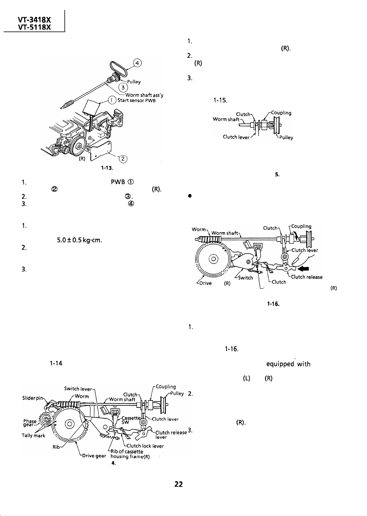
REPLACEMENT OF CASSETTE LOADING
BELT
Cassette
Remove the start sensor
Remove the worm shaft assembly
Replace the cassette loading belt
Notes:
housing frame
bracket
Figure
from the cassette housing frame
Worm bracket
and worm
with a new
one.
Do not over-tighten the B tight screw which holds
the worm bracket in position. The specified
torque is
0.5
Make sure that the cassette loading belt is free
from grease.
If stained with grease, clean the
belt with the cleaning liquid.
Perform checking of the clutch switch lever for
proper action.
CHECKING THE CLUTCH SWITCH LEVER
l
Checking
Place the mechanism in the cassette eject mode
when removing and attaching the cassette
housing from and to the mechanism chassis.
Make sure enough that each part in the cassette
housing such as the clutch switch lever is in
position. If not, it causes malfunction.
Note:
Figure
the cassette eject mode.
shows the position of each part in
Figure l-l
First make sure that the tip of the switch lever is
held at the rib of the drive gear
Check that the rib of the cassette housing frame
and the concavity of the clutch lock lever are
engaged.
Finally be sure that the relationship between the
clutch lever and the clutch, as well as between
the clutch and the pulley, are correct as in the
Figure l-1
.
Check that the clutch is engaged
with the pulley through the coupling.
Figure l-l
Resetting
Take the following steps to reset the clutch if it is
unlocked or if the switch lever and the clutch
lock lever are unlocked.
lever
gear
lever
Rib of cassette housing frame
Figure
lock lever
6.
Shift the slider by turning the coupling in the
arrow direction (clockwise) until the slider pin is
at the bottom of the slider groove as shown in
the Figure l-16. (The loading mode)
Note:
Note that the slider is
mechanism.
housing frames
Unlock the locks on cassette
and
side before shifting
a lock
the slider.
When the position is set as shown in the Figure 4-
16, push the clutch release lever in the direction
of the arrow by hand until the clutch lock lever
becomes tightly locked by the rib of the cassette
housing frame
Then turn the coupling counterclockwise until
the slider reaches the cassette insertion opening
and the reciprocating spring is activated.
Note:
There is no need to unlock the slider when
shifting the slider to the cassette insertion
opening. Just keep shifting the slider.
Page 23
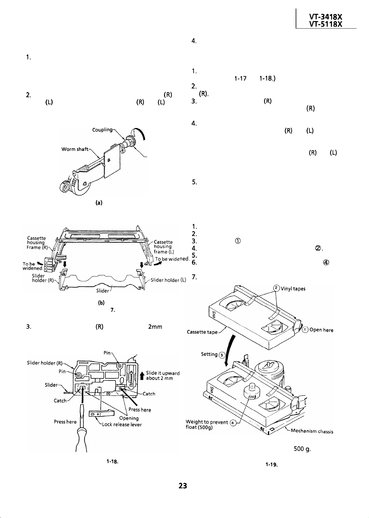
REPLACEMENT OF LOCK RELEASE LEVER
l
Removal
Place the slider in the cassette down position.
(Turn the coupling on the worm shaft clockwise
until the slider is in the cassette down position.)
Note:
Before shifting, unlock the slider.
Slightly widen the cassette housing frames
and
the slider assembly off the grooves of the
cassette housing frames.
to unhook the slider holders
and
Pulley
of
Remove the lock release lever from the slider
holder(R)
l
Reassembly
Follow the steps for removal in the reverse order.
(See Figures
and
Attach the lock release lever to the slider holder
Slide the slider holder
two catches of the slider holder
downward so that the
fit the
opening of the slider.
Slightly widen the cassette housing frames, and
set the pins of slider holders
and
into the
grooves of the cassette housing frames.
Note:
Check if the pins of the slider holders
and
fit the grooves of the cassette housing frames,
and if the drive gear arm is sufficiently engaged
with the slider holders.
Turn the coupling counterclockwise until the
slider is at the cassette insertion opening.
TO RUN A TAPE WITHOUT THE CASSETTE
HOUSING CONTROL ASSEMBLY
Plug in the power cord.
Turn on the power switch.
Open the lid
Hold the lid with two pieces of vinyl tape
Set the cassette tape in the mechanism chassis.
Stabilize the cassette tape with a weight
prevent floating.
Perform running test.
of a cassette tape by hand.
to
Figure l-l
Lift the slider holder
upward about
the slider by pressing two catches with a thin tip
screw driver.
catches.
Take care not to damage the
lock catch
Figure
/-Slide
off
Note:
The weight should not be more than
Figure
Page 24
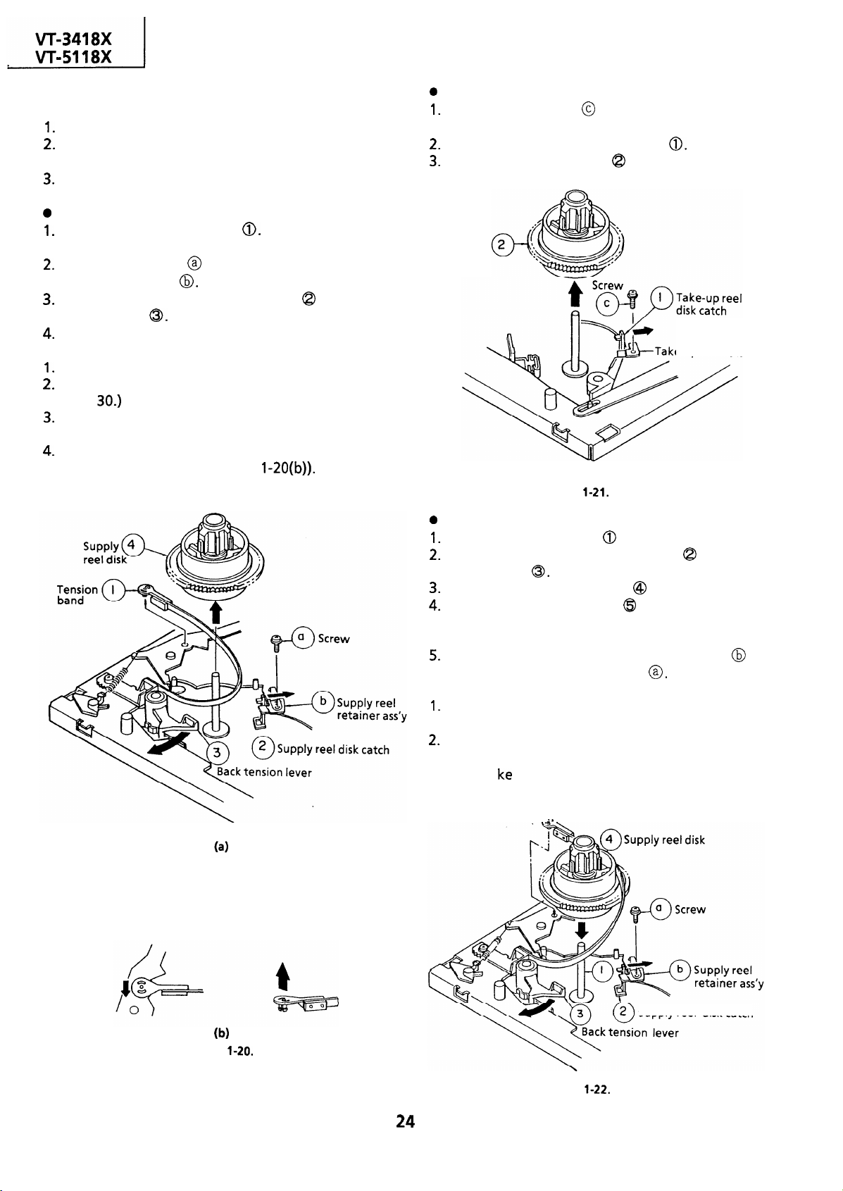
REPLACEMENT AND HEIGHT CHECKING
AND ADJUSTMENT OF REEL DISKS
Remove the cassette housing control assembly.
Set the mechanism in the playback mode with no
cassette tape in place. Unplug the power cord.
Set the idler gear in the center (neutral).
Removal (Supply reel disk)
Remove the tension band
deform it.)
Unscrew the screw @ and remove the supply reel
retainer assembly
Release the supply reel disk catch
tension lever
Pull the supply reel disk upward.
Notes:
Take care not to deform the tension band.
Check and adjust the tension pole position. (See
page 30.)
Be careful not to damage the gear and the idler
gear on the supply reel disk.
Press the tension band in the direction of the
arrow for removal (See Figure
(Take care not to
and back
Removal (Take-up reel disk)
Unscrew the screw
and remove the take-up
reel retainer.
Release the take-up reel disk catch
Pull the take-up reel disk
Take-up
reel disk
Figure
upward.
e-up reel
retainer
Note:
When the tension band is pressed in the direction
of the arrow for removal, the catch is hard to be
deformed.
Reassembly (Supply reel disk)
Clean the reel disk shaft
Release the supply reel disk catch
and apply oil to it.
and back
tension lever
Install a new supply reel disk
Replace the tension band
onto the shaft.
around the supply
reel disk, and insert it to the hole of the tension
arm.
Replace the supply reel retainer assembly
place, and tighten up the screw
Notes:
Take enough care not to deform the tension
band during installation of the supply reel disk.
Be careful not to damage the supply reel disk
gear, back tension lever, supply reel disk catch,
or the Ii
with tools.
5 Tension band
Q
in
Figure
Figure
Supply reel
disk catch
Page 25
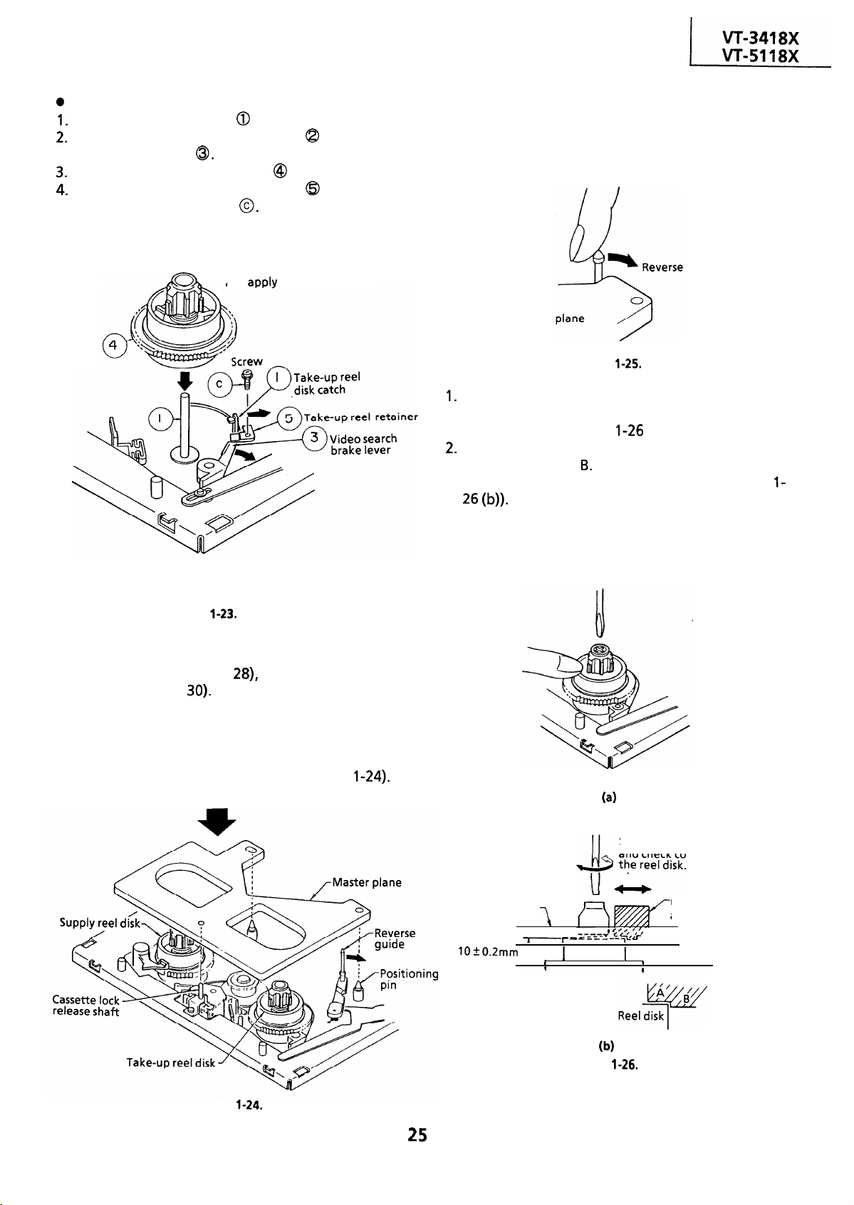
Reassembly (Take-up reel disk)
Clean the reel disk shaft
Release the take-up reel catch
and apply oil to it.
and video
search brake lever
Install a new take-up reel disk @ onto the shaft.
Replace the take-up reel retainer
in position
and tighten up the screw
Note:
Take care not to damage the video search brake
lever.
Take-up
reel disk
Apply a thin tip driver to the arrow position in
releasing for easier setting of the take-up reel disk.
Clean the reel disk shaft well,
and
oil to it.
Set the master plane releasing
the reverse guide by a finger.
guide
Master
Figure
For height adjustment, press the reel disk with a
finger, and turn it right and left with a
screwdriver (see Figure
(a)).
Check that the reel disk is lower than part A but
higher than part
If the height is not correct,
adjust the height adjusting screw (see Figure
Note:
Whenever replacing the reel disk, perform the
height checking and adjustment.
Figure
* After reassembly, check the video search rewind
back tension (see page
and check the brake
torque (see page
l
Height checking and adjustment
Note:
Place the master plane onto the mechanism unit,
taking care not to hit the drum (see Figure
Setting
Master plane
L
Reel disk
Slide it right and left,
and check contact with
Reel disk height
‘,‘, ,
adjusting jig
‘-
/Mechanism chassis
’
Figure
Figure
Page 26
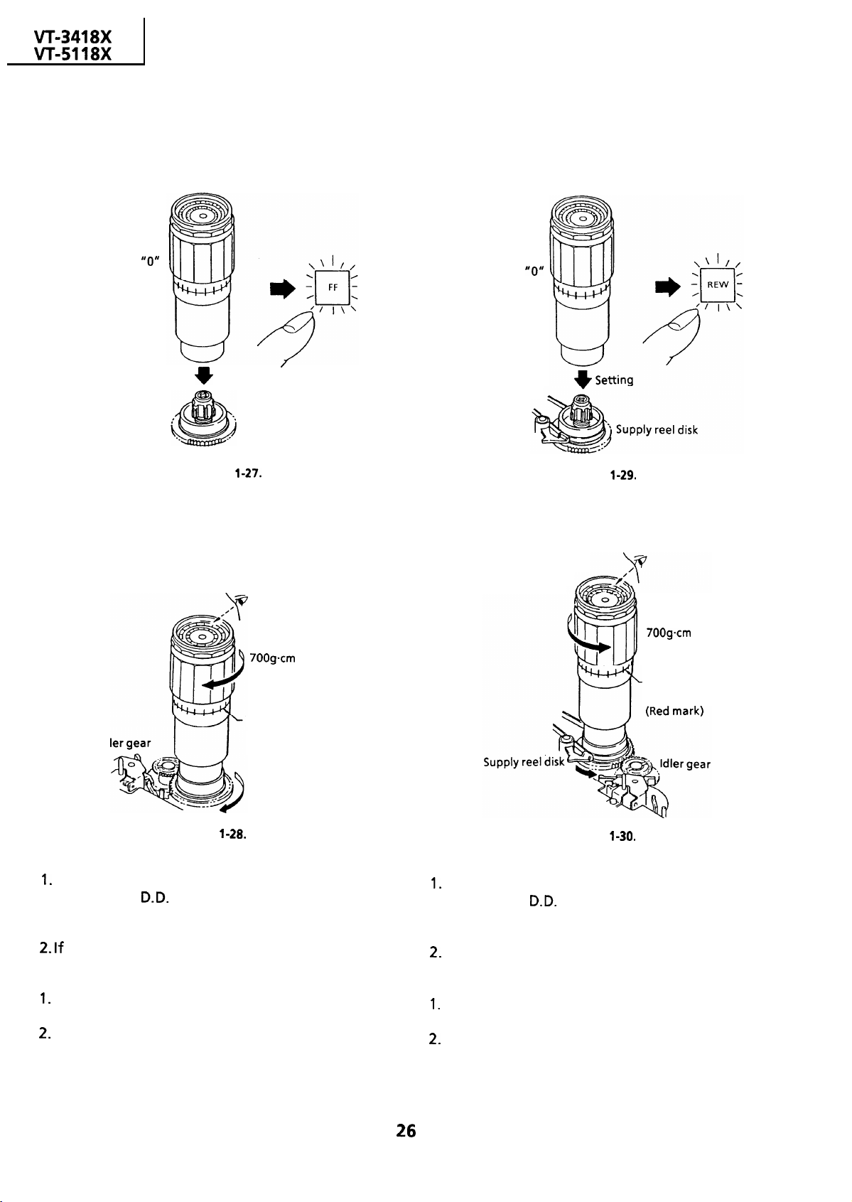
CHECKING AND ADJUSTMENT OF TAKE-UP
TORQUE IN FAST FORWARD MODE
l
Remove the cassette housing control assembly.
l
Setting
Torque gauge
CHECKING AND ADJUSTMENT OF TAKE-UP
TORQUE IN REWIND MODE
l
Remove the cassette housing control assembly.
l
Setting
Torque gauge
Set the scale to
l
Checking
Turn the torque gauge slowly
(one rotation every 2 to 3
seconds) by hand in the
take-up direction
Setting
Figure
Take-up reel disk
or more
Set the scale to
l
Checking
Turn the torque gauge slowly
(one rotation every 2 to 3
seconds) by hand in the
take-up direction
Figure
or more
The gauge is held at
its maximum value.
The gauge is held at
Id
Figure
l Adjustment
its maximum value.
(Red mark)
Take-up direction
If the take-up torque is outside the range, clean
the capstan
motor pulley, reel belt and reel
pulley with cleaning liquid, then recheck the
torque.
If the take-up torque is still out of range, replace
the reel belt.
Notes:
Hold down the torque gauge so that it may not
fly off.
When checking the take-up torque, do not keep
the reel disk locked for a longer time.
Figure
l
Adjustment
If the take-up torque is outside the range, clean
the capstan
motor pulley, reel belt and reel
pulley with cleaning liquid, then recheck the
torque.
If the take-up torque is still out of range, replace
the reel belt.
Notes :
Hold down the torque gauge so that it may not
fly off.
When checking the take-up torque, do not keep
the reel disk locked for a longer time.
Page 27
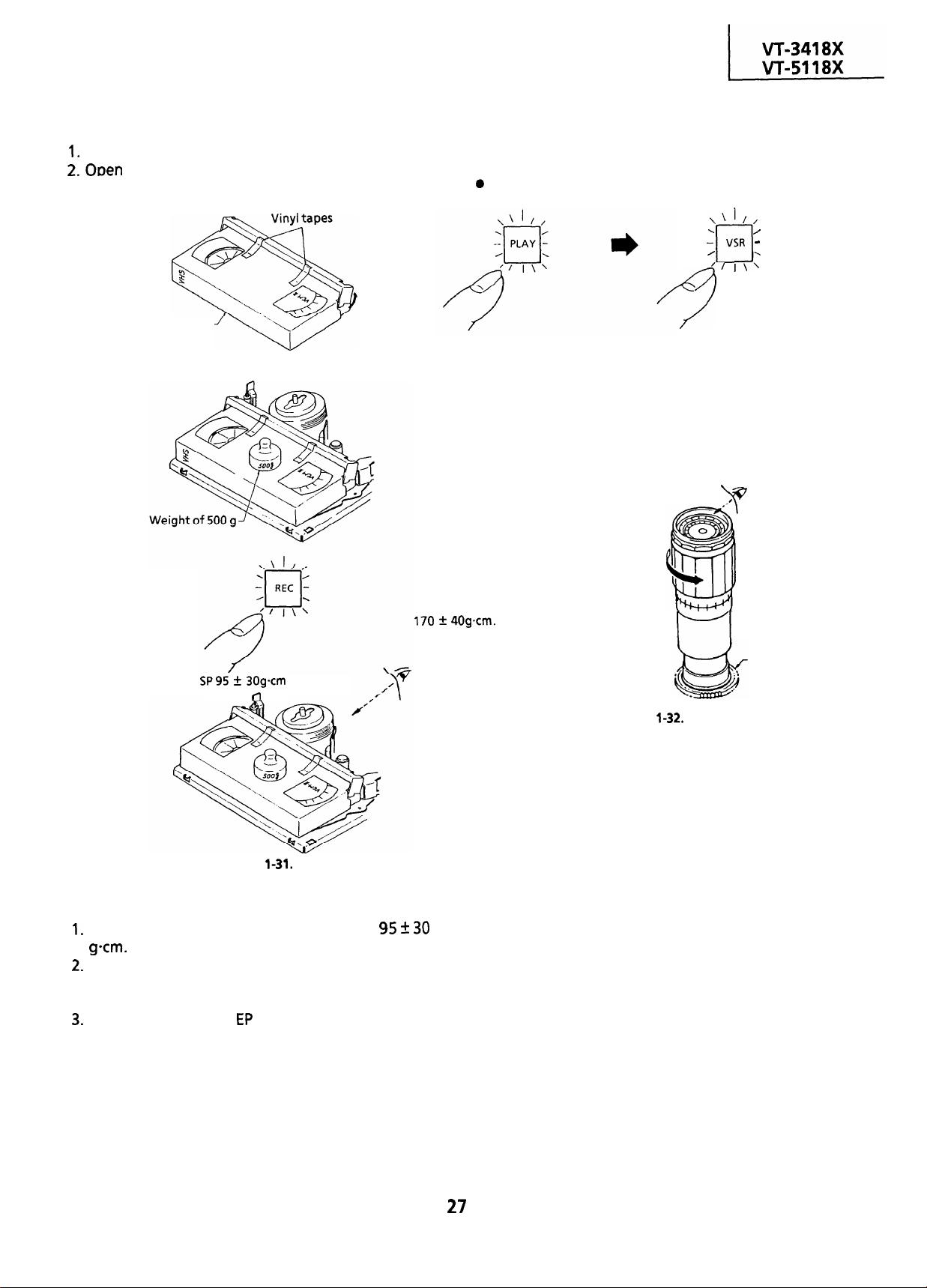
CHECKING AND ADJUSTMENT OF TAKE-UP
TORQUE IN PLAYBACK MODE
Remove the cassette housing control assembly.
the lid of the cassette torque meter, and
hold it with two pieces of vinyl tapes.
Open here
Cassette torque meter
Load a cassette torque meter into the unit.
CHECKING AND ADJUSTMENT OF TAKE-UP
TORQUE IN VIDEO SEARCH REWIND MODE
l
Remove the cassette housing control assembly.
Checking
Push the play button to place
the unit in the playback mode.
Push video search rewind
button to place the unit in the
video search rewind mode.
Torque gauge
Figure
l
Checking
Set value
Check that the torque is in the range of
The torque fluctuates due to the rotational
deviation of the reel drive unit. Use the center of
the fluctuation as the value.
Place the unit in the
record mode, and check
that the take-up torque is within the range.
Place the torque gauge on the supply reel
disk, and turn it counterclockwise very slowly
(one rotation every 2 to 3 seconds) and check
that the torque is within the set value
Figure
Note:
Set the torque gauge securely on the supply reel
disk. If it is not secure, the measurement will be
incorrect.
l
Adjustment
If the take-up torque in video search rewind mode
is outside the range, replace the supply reel disk.
Note:
The torque fluctuates due to the rotational
deviation of the supply reel disk. Use the center of
the fluctuation at the value.
Supply reel disk
l
Adjustment
If the take-up torque in the playback mode is
outside the range, replace the take-up reel disk.
Note:
Stabilize the cassette torque meter to prevent
floating.
Page 28
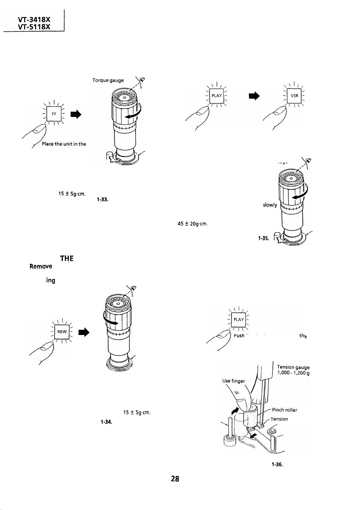
CHECKING THE FAST FORWARD BACK
TENSION
l
Remove the cassette housing control assembly.
l
Checking
CHECKING THE VIDEO SEARCH REWIND
BACK TENSION
Remove the cassette
l
l
Checking
housing control assembly.
fast forward mode.
Place the torque gauge on the supply
reel disk, and turn it clockwise very
slowly (one rotation every 2 to 3 seconds)
and check that the torque is within
Figure
Supply reel disk
Note :
Set the torque gauge securely on the supply reel
If the torque gauge is not securely set on the
disk.
reel disk, measurement will be incorrect.
CHECKING
l
l
Check
REWIND BACK TENSION
Push the play button to place
the unit in the playback mode. button to place the unit in the
Place the torque gauge on the take-up reel
disk, and turn it counterclockwise very
(one rotation every 2 to 3 seconds) and check
that the torque is within the set value
5 2Ogcm.
Push the video search rewind
videosearch rewind mode.
Torque gauge
Figure
Take-up
reel disk
Note :
Set the torque gauge securely on the take-up reel
disk. If it is not secure, the measurement will be
incorrect.
CHECKING THE PINCH ROLLER PRESSURE
Remove the cassette housing control assembly.
l
Place the unit in the
Take-up reel disk
rewind mode.
Place the torque gauge on the
take-up reel disk, and turn it
counterclockwise very slowly
(one rotation every 2 to 3
seconds) and check that the
torque is within
Figure
Note:
Set the torque gauge securely on the take-up reel
disk. If it is not secure, the measurement will be
incorrect.
unit in the playback mode.
Capstan shaft
Figure
Page 29
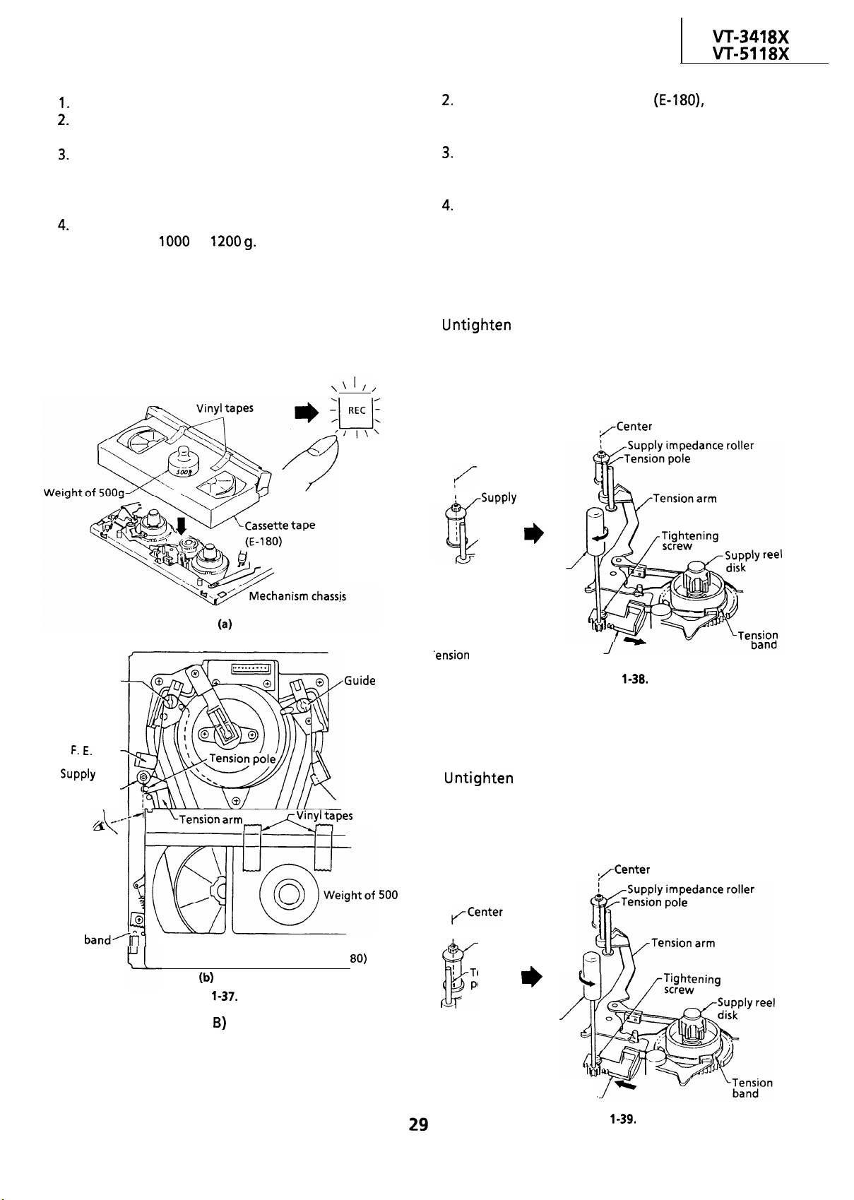
Detach the pinch roller from the capstan shaft.
Set the tension gauge by hooking the tension
gauge adapter onto the pinch roller shaft.
Gradually release the pressure to allow the pinch
roller to touch the capstan shaft. When the
pinch roller just touches the capstan shaft, read
the indication on the gauge.
Check that the reading of the tension gauge is in
the range of
to
CHECKING AND ADJUSTMENT OF TENSION
POLE POSITION
l
Remove the cassette housing control assembly.
l
Setting
At the beginning of the tape
check that
the tension pole’s left side is aligned with the
supply impedance roller’s center by sight.
Check that the end of the tape is neither curled
against the flange of the supply impedance
roller nor over it.
During the video search rewind mode with no
cassette tape in place, check that the supply reel
disk is free from the tension band.
l
Position adjustment (record mode)
When the tension pole is at the right of the supply
impedance roller’s center:
tension band adjustment bracket in the direction of
the arrow using a tension band and plate adjusting
Jig until it is in the set value range (center). Then
secure it with the tightening screw.
Guide roller A
head
impedance.
roller
Check the left
side position
(by sight).
Place the unit in
the record mode.
T
roller B
Center
I
impedance
roller
Tension
pole
Tension band
and plate
adjusting jig
Figure
l
Position adjustment (record mode)
When the tension pole is at the left of the supply
impedance roller’s center:
tension band adjustment bracket in the direction of
the arrow using a tension band and plate adjusting
Jig until it is in the set value range (center). Then
secure it with the tightening screw.
Tension
and plate
adjusting jig
setting hole
l
Checking
I. The guide rollers (A,
Figure
Video Cassette tape (E-l
operate to bring the tape
outside the cassette tape and simultaneously the
tension pole moves to the left, loading the tape.
At that time (loading completed), check the
position of the tension pole.
g
I
I
Supply impedance
roller
Tension
pole
Tension band
and plate
adjusting jig
Tension band adjustment bracket
Figure
Page 30
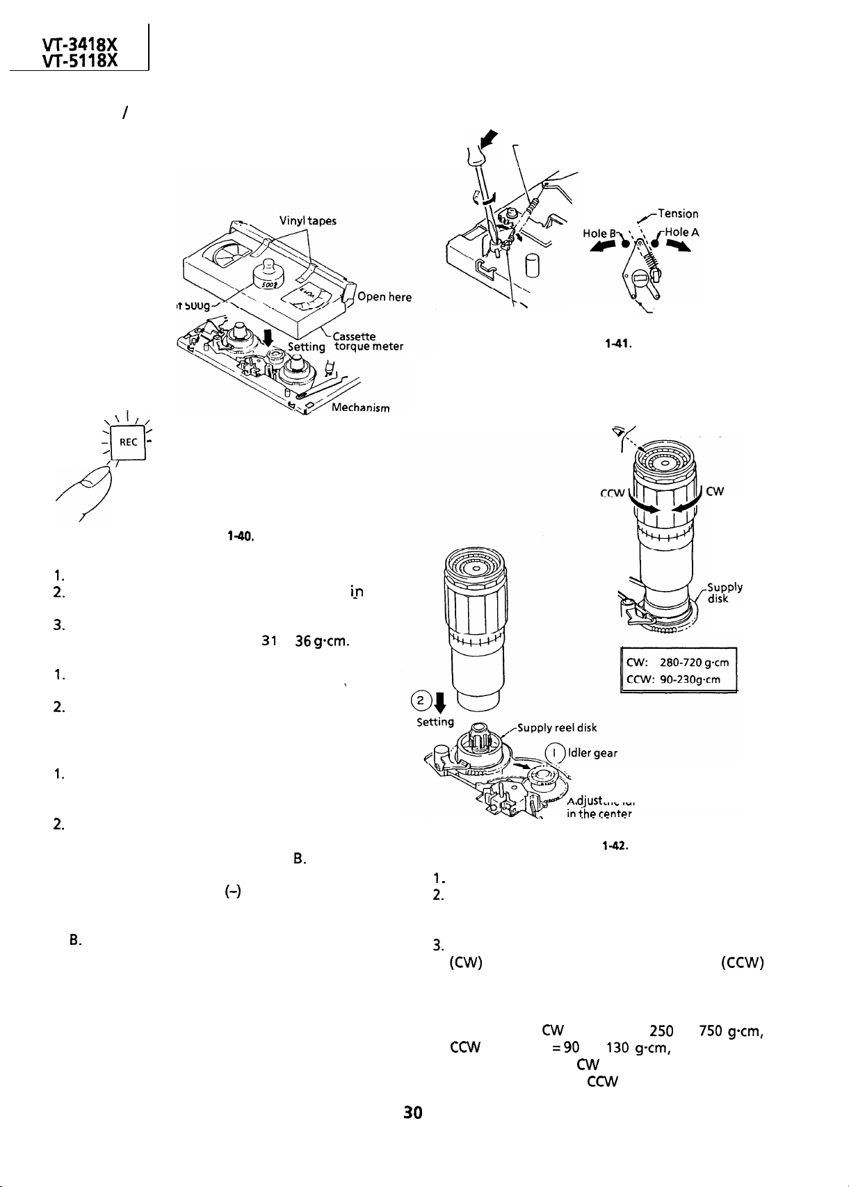
CHECKING AND ADJUSTMENT OF
RECORD
l
Remove the cassette housing control assembly.
l
Checking
PLAYBACK BACK TENSION
Tension spring
spring
Weight a
chassis
.
I\’
Push the record button
to place the unit
in the record mode.
Figure
Put a cassette torque meter into the unit.
Push the record button to place the unit
record mode.
Check that the back tension indicated by the
gauge is within the set range
Notes:
Make sure that the video cassette tape is over
the retaining guide.
Make sure that the tape is not slack nor
damaged at either end.
to
the
Tension spring hook plate
Figure
Tension spring
hook plate
CHECKING THE BRAKE TORQUE
l
Checking the brake torque at the supply side
Torque gauge
reel
l Adjustment
If the reading of the cassette torque meter is less
than specified, move the tip of the tension spring
hook plate toward the hole A.
If the reading of the cassette torque meter is
more than specified, move the tip of the tension
spring hook plate toward the hole
Note:
Put a thin screw driver
it toward you, and turn it for easier shift of the
tension spring hook plate in the direction of A or
in the shaft hole, lean
idler gear
Mechanism chassis
Figure
Remove the cassette housing control assembly.
Place the mechanism in the stop mode by
unplugging the power cord in the fast forward
or rewind mode.
Slowly rotate the torque gauge in the clockwise
direction and counterclockwise
direction of the supply brake so that the reel disk
and the indicator of the torque gauge rotate at
an equal rate. Check that the values are within
the range of
direction
brake torque in the
as high as that in the
direction =
to
direction is at least twice
direction.
to
and that the
Page 31

l Checking the brake torque at the take-up side
chassis
REPLACEMENT OF MAIN BRAKE
Remove the reel belt and the reel block
Flat Cable).
Remove the cut washer
Unscrew the four screws
up reel retainer.
Remove the reel block assembly
Remove the cut washer
pulley.
Unscrew the two screws
assembly.
Unhook the back tension lever spring
remove the back tension lever
hook under the reel chassis.)
Open the shifter latch
shifter assembly
Release the reel disk catchesand
the left and right reel disk assemblies
Finally remove the main brake levers
main brake spring
off the brake shifter.
and then the
downward.
first and then the reel
and detach the idler
and remove the brake
then remove
.
(Full
and
(Undo the
and
and the
Figure
Remove the cassette housing control assembly.
Slowly rotate the torque gauge in the clockwise
direction and counterclockwise
direction of the take-up brake so that the reel
disk and the indicator of the torque gauge
rotate at an equal rate. Check that the values
are within the range of
direction
that the brake torque in the
direction
to
to
and
direction is at
least twice as high as that in the CW direction.
Adjustment of the brake torque at the supply
side and the take-up side
If the supply or take-up brake torque is outside
the range, clean the supply or take-up reel disk
break lever felt, then recheck the torque.
If the supply or take-up brake torque is still
outside the range, replace the main brake or the
main brake spring.
Figure
Note:
When the main brake is replaced, perform the
height checking and adjustment (see page
and
the brake torque checking (see page
Page 32

REPLACEMENT OF A/C (Audio/Control)
HEAD
Remove the cassette housing control assembly.
Place the unit in the unloading mode, and
unplug the power cord.
l
Removal
Loosen the tilt adjusting screw
Remove the azimuth adjusting screw
Remove the A/C head screw
Unsolder the A/C head
head assembly.
Notes:
After replacement, be sure to perform the
adjustment of the tape drive train (see page
Under any circumstances, avoid touching the
head. Clean the head, if touched with your
finger, with alcohol.
Take care that the azimuth spring does not fly
off when removing the A/C head screw.
4
soldered to the
Figure
l
Adjustment
[A/C head tilt angle]
Set the mechanism to the loading mode.
Place the A/C head tilt adjusting Jig
3 Slowly turn the tilt adjusting screw
screw driver until there is no gap between the Jig
and the A/C head.
with a
Pay attention to
Figure
l
Replacement
Solder the removed A/C head
A/C head assembly.
The A/C head assembly is attached so that the
A/C head arm and
parallel to each other.
head plate are roughly
onto a new
Solder
A piece of white paper
1
Screw driver
New
head
Never touch the head
head arm
Figure 1-48.
Page 33

[A/C head height rough adjustment]
head
adjusting
Weight
Roughly adjust the height
of the AK head by turning
the
head adjusting
hexagon nut with the
specialized box drive until
the tape is in the position
shown
Reverse guide
adjusting jig
of 5009
chassis
HEIGHT ADJUSTMENT OF REVERSE GUIDE
Note:
Before the rough adjustment of the tape drive
train, check that the retaining guide height is
within the value in Figure
Jigs.
height-\
-Reverse guide
Reverse guide
height
.
To readjust the height, remove
the cut washer from behind,
take out the spring, lift the
reverse guide and add a
washer.
by using the special
7
Reverse guide
head
Adjust the nut visually so that
.
the control head is visible
to
mm below the bottom
of the tape.
Figure
Adjust the height using
of washers
Spring
Mechanism chassis
.-Spring
(iron flat)
washer
Figure
Page 34

8X
ADJUSTMENT OF TAPE DRIVE TRAIN
Remove the cassette housing control assembly.
Check and adjust the position of the tension
pole. (See page
Check and adjust the video search rewind back
tension. (See page 28.)
Set the tilt angle of the A/C head. (See page
Rough adjustment of tape drive train.
Connect the oscilloscope to the test point for
the synchronism of the oscilloscope to EXT.
The
the head switching pulse
Loosen the setscrew at the lower part of the
guide roller, and adjust it with an adjusting
screw driver
roller turns smoothly. (Do not overloosen the
setscrew, which causes insecurity of the guide
roller.) (See Figure
Set the alignment tape (monoscope pattern)
on the reel disk, and place the unit in the
playback mode.
(Place a
prevent floating of the cassette tape.)
envelope output
signal is to be triggered by
so that the guide
g weight on the cassette tape to
Set
Wrinkles at upper flange
Wrinkles at lower flange
Clockwise
Counterclockwise
Guide roller
Hexagon
Figure
Figure
Change the envelope waveform from MAX to
or
is obtained on the waveform.
adjust the guide rollers on the supply side and
take-up side using an adjusting screw driver
until a flat response can be obtained.
Turn the
head tilt adjusting screw with a
screwdriver to prevent the tape from
wrinkling at the upper and lower flanges of
the fixed guide.
Wrinkles at the upper flange
Turn the
above adjusting screw clockwise, as shown
in Figure
(a).
Wrinkles at the lower flange : Turn the
above adjusting screw counterclockwise, as
shown in Figure
Figure
Notes:
Place the tracking control in the center position,
and adjust the X-position adjusting nut so that
the
envelop becomes maximum for
easier rough adjustment of the tape drive train.
In the rough adjustment, pay particular
attention to the outlet side.
. .
Loosen the setscrew o
Figure 1-54.
Figure
X-position
adjusting nut
Page 35

Head switching pulse
envelope
Azimuth adjusting
screw
Figure
Adjustment of A/C head height and azimuth
a) Connect an oscilloscope to the audio output.
(Pin
of EL connector)
Use the alignment tape and play back its
audio 7
signal (monoscope pattern for
video signal). Adjust the azimuth adjusting
screw to obtain the maximum audio output
on an oscilloscope. (See Figure
Use the alignment tape and play back its
audio 1 kHz signal (colour bar for video signal)
and slowly rotate the A/C head height
adjusting nut with the special box driver to
obtain the maximum audio output.
Perform the adjustment in
again.
After this adjustment, apply glyptal to the
screws and nuts to fix them.
Figure
Figure
Adjustment of tape drive train and X-Position.
a) Connect the oscilloscope to the test points
for
CHROMA envelope output.
Set the synchronism of the oscilloscope to EXT.
The
signal is to be triggered by
the head switching pulse (TP2202).
Play back the tape drive train alignment tape.
Push the
envelope waveform from MAX to
or
button to change the
and
on the supply and take-up sides with an
adjusting screw driver, to obtain an envelop
waveform that is as flat as possible.
If the tape is above or below the helical lead,
the
waveform will take the shape
shown in Figure
Adjust for maximum flatness of the envelope
the step in page
Adjustment
When the tape is above the helical lead.
Supply side
Take-up side
Supply side guide Take-up side guide
roller rotated in roller rotated in
clockwise direction
(lowers guide roller) to
flatten envelope. flatten envelope.
clockwise direction
(lowers guide roller) to
Figure
When the tape is below the helical lead.
Supply side
Supply side guide
roller rotated in
counterclockwise
direction (raises guide
roller) to make the
tape float above the
helical lead. The supply
side guide roller is
then rotated in the
clockwise direction to
flatten the envelope.
Take-up side
Take-up side guide
roller rotated in
counterclockwise
direction (raises guide
roller) to make the
tape float above the
helical lead.
The take-up side guide
roller is then rotated in
the clockwise direction
to flatten the
envelope.
Page 36

8X
Push the
that a flat response is obtained on the
envelope waveform.
Secure the guide roller by tightening the
guide roller setscrew in the unloading mode.
Play back the tape drive train alignment tape
to check that the envelope waveform does
not change.
Adjustment of A/C head X-position.
a) Push the (
same time to the preset mode.
Rotate the X-position adjusting nut with an
adjusting box driver, and adjust the
position for maximum head switching pulse
low side envelope.
Adjust the playback switching point.
Check the flatness of the envelope waveform
and sound by playing back a recorded tape.
X-position adjusting
or (-) tracking button to check
and
tracking buttons at the
nut
head
l
Reassembly
Mount the capstan motor on the mechanism
chassis making sure not to allow the capstan
shaft to hit the mechanism chassis, and attach it
with the three screws.
Insert the
into the capstan
motor
control
Attach the reel belt.
Notes:
After installing the capstan
to rotate the capstan
motor, be sure
motor and check the
movement.
Check and adjust the servo circuit.
REMOVAL AND REASSEMBLY OF THE
LOADING GEAR BLOCK
Notes:
Remove the cassette housing control assembly.
Remove the reel belt.
Remove the reel block.
mm
Main
chassis
Figure
REPLACEMENT OF THE CAPSTAN D.D.
(DIRECT DRIVE) MOTOR
l
Remove the cassette housing control assembly.
l Removal (Follow the order of
numbers.)
Remove the three screws.
l
Notes:
Remove the washer
Removal
Use care not to deform the parts hooked to the
slow brake shaft cap, take-up loading gear and
supply loading gear as shown in Figure
Figure
in removing the loading gear, secure the guide
roller with a rubber band or the like beforehand
for easier reassembly.
Remove the E-ring
Loading relay gear
Figure 1-61.
Figure
Page 37

Remove the slow brake spring
Remove the washer
Remove the slow brake lever
Remove the E ring
Rotate the take-up loading gear, take-up
loading arm assembly, supply loading gear and
supply loading arm assembly slightly in the
loading direction, and take them
all out.
Remove the E ring
Remove the relay gear drive lever
Reassembly
Reverse the procedure. Be sure to match the
tally marks on the gears.
Screws
Figure
Note:
When using a magnetic screw driver in removal of
three screws, do not allow the magnetic driver to
hit the A/C head or drums.
Figure
Notes:
When reassembling, apply specified grease to
the following points; all the gear teeth, all the
gear shafts and the cam groove of loading relay
gear.
Be careful not to deform the supply/take-up
loading arms.
Be careful to keep clean the slow brake lever felt.
Be also careful to keep the outer surface of the
capstan
motor free from dust and dirt. (If
stained, the MR (Magnet Resistor) element
might be damaged.)
Take care not to deform the anti-fall hooks of
the slow brake lever, slow brake shaft cap and
supply/ take-up loading gears more than
required.
REMOVAL AND REASSEMBLY OF LOADING
BLOCK
l
Removal
Remove the cassette loading belt
Unscrew the three screws
Pull the loading block upward.
Reassembly
Turn the master cam all the way counterclockwise.
the tally mark on the cam switch with the
matching mark.
Fit the loading block and the
master cam with each other. Tighten up the
three screws.
Tally mark
Cam switch
Figure
Finally connect the leads and apply the cassette
loading belt.
Notes:
Be careful not to scratch the gear.
Be careful not to stain the belt. If dirty, clean it
up with the specified cleaning liquid.
REPLACEMENT OF LOADING MOTOR
Set the cassette ejected condition by placing the
unit in the cassette eject mode.
Unplug the power cord.
Remove the loading block in accordance with
the statements and drawings above.
Page 38

8X
I
Removal
Figure
Unsolder the leads
Unlock the left and right catches
switch off the loading block. Take out the cam
switch and loading block
from the loading motor.
of the cam
(See Figure
marks
block
Loading mot
Note:
When press-fitting the loading
motor pulley, keep the pressure
less than 5 kg, and the gap
between the motor and pulley
should be
Figure
Set the loading block
position.
Resolder the leads to the loading motor.
Finally place the loading block (See page
Attach the loading belt.
Figure
and the cam switch in
mm
mm.
Pull up the cam switch pressing
the catches. Remove the cam switch
Catches of cam switch
Take out the loading belt
Pry up the back end of the loading motor with a
screw driver or the like as in Figure
out the motor.
screwdriver or the
like here. Pry UP the
back end of the
loading motor and
take out the motor.
l
Reassembly
Remove the loading motor, and mount a new
loading motor as in Figure
Place the loading motor so that its label is visible
as
screw hole at the motor shaft, protuberance *on
the
marked with the arrow are mated with each
other.
a
in Figure
block, and the motor’s back end
together with the loading btock
Figure
and take
Motor label
Figure
Make sure that the
Loading belt
Q
REPLACEMENT OF MASTER CAM
l
Removal
Remove the E ring
Remove the pinch roller lever
Pull out the master cam
Master cam
I
upward.
Pinch roller lever
Pinch
roller lever
Bottom side of
master
lever cam follower
(Place the relay shifter
lever to the unloading position.)
brake lever cam follower
Figure
cam
cam
Page 39

Reassembly
Place the relay gear drive lever in the unloading
state.
Place the relay shifter so that it is in contact with
the reverse guide spring hole in the mechanism
chassis. Release the slow brake lever with a
finger to bring it away from the capstan (in the
direction of arrow). Then place the master cam
so that the D cut-off part of the master cam faces
the direction of arrow.
Turn the master cam somewhat clockwise until
the pinch roller lever’s cam follower goes into
the master cam’s groove (marked with arrow).
Mount the pinch roller lever and then attach the
E ring.
Rotate the master cam by hand to make sure all
the four levers (relay gear drive lever, pinch
roller lever and relay shifter lever) are in the cam
grooves in place.
Mount the loading block. (See page
Notes:
Be careful not to scratch the teeth and grooves
of the master cam.
After installation of the master cam, be sure to
rotate the master cam by hand before installing
the loading block.
If the levers are in wrong
position, the master cam and the levers may get
damaged when the motor stares.
Apply specified grease to the master cam’s
3
grooves and teeth.
Unsolder the leads.
and tighten the
Turn
Figure
l
Reassembly
Notes:
Before setting the drum, check that there are no
scratches or dust on the edge of the surface and
circumference of the disk.
Before setting the drum, check that there are no
scratches or dust on the internal surface and
edge of the surface of the upper drum.
On assembling these parts, insert the upper
drum onto the disk with care, so that the upper
drum is not tilted.
When assembling these parts, do not allow dust
or dirt come between the disk and the upper
drum.
Do not use excessive force when driving in the
screws.
REPLACEMENT OF UPPER DRUM
Note:
The gap between the lower drum and the upper
drum is very accurate, in the order of microns, and
care should be paid to their replacement. Even a
slight amount of foreign material will affect the
accuracy of their reassembly.
l Replacement (Follow the order of the indicated
numbers.)
Notes:
Avoid touching the drum surface
hands.
Pull out the upper drum with care so that it may
not be tilted, and replace it with the upper drum
replacing jig using care not to damage the disk
circumference.
Do not hit the screws when tightening them.
Figure
Set the new drum.
Fasten the upper drum in place with the two
screws.
Solder the leads.
Note:
Soldering should be performed quickly and
carefully without touching adjacent patterns.
After replacement, be sure to check the tape
drive train adjustment (see page 34.) and the
following electric adjustments.
l
Adjustment of the playback switching point.
l
Checking and adjustment of the X-position.
l
of
and
slow
Page 40

8X
18X
REPLACEMENT OF D.D. MOTOR
Put the unit in the cassette eject position.
Unplug the power cord.
l
Removal (Reverse the order in reassembly.)
Remove the
Remove the two
Pull out the
Remove the three
Remove the
Notes:
When removing the
assembly, use care not to hit the loading
relay gear.
Secure the
installation positioning holes in the
assembly and lower drum assembly match.
Be careful not to damage the upper drum or the
video head.
Be sure that the hall device and the
assembly are not damaged by the
assembly or other parts.
After installation, adjust the playback switching
point.
rotor assembly setscrews
rotor
stator setscrews
stator assembly
rotor assembly or
rotor assembly so that the
rotor
rotor
REPLACING THE
CLEANER)
(AUTOMATIC HEAD
setscrew
Figure
setscrew
positioning
rotor
Figure
l
Removal
Unhook pat-t
ass
,
arrow.
with a finger in the direction of
Hold the rib (marked with an arrow) of the
with electrician’s pliers or the like, and
pull the
upward in the direction of arrow
Note:
To pull out the AHC
l
Reassembly
Push down the
arrow
Make sure that the
hold the AHC lever down.
in the direction of
is secured in
position by the hook of part
Notes:
Be careful to keep the
out of contact
with the drum.
Be careful to keep the cleaner section of the
free of grease of contaminants.
Page 41

ADJUSTMENT OF THE
VCR ELECTRICAL CIRCUITRY
Notes:
Before the adjustment:
Electrical adjustments discussed here are often required after replacement of electronic
mechanical parts such as video heads.
Check that the mechanism and all electric components are in good working condition prior to the
adjustments, otherwise adjustments can not be completed.
l
Instruments required:
signal generator
e oscilloscope
milli-voltmeter
Frequency counter
Blank video cassette tape
Screwdriver for adjustment
n
SERVO CIRCUIT ADJUSTMENT
Adjustment of head switching point
Measuring
instrument
Dual-trace oscilloscope
voltmeter
@Alignment tape
Extension connector
AL
AL)
Mode
Cassette
Test point
Control
Specification
Play the alignment
Short circuit test points
the A/V Jack
housing
(See Note below)
Connect a dual trace oscilloscope to the VIDEO
OUT (pin
(Trigger the oscilloscope with the head
switching pulse on TP2202.)
Adjust
head switching pulse is 6.5H (lines) ahead of the
vertical sync as shown in Figure
Playback
Alignment tape
VIDEO OUT (pin
connector) to
(Trigger) to
(Located on the Y/C
head switching point
adjustment control
H (lines)
or remove the cassette
to set the auto tracking to center.
of EL connector) and TP2202.
so that the leading edge of the
of EL
1
and
on
HEAD .
SWITCHING
PULSE
Figure
Notes:
To make this adjustment, disable the AUTO
TRACKING function.
The AUTO TRACKING function is disabled in the
following cases.
(In the playback mode only.)
the cassette housing control
removed, press both tracking control buttons of
the remote control unit at the same time to set
the tracking in center.
When test points
jack
are short-circuited.
(lines)
and
V-sync.
is
on the A/V
Page 42

n
Test points layout of VCR Main Unit.
I
1
I
0
I
Adjustment of PAL System
tracking Preset
Measuring
instrument
Mode
Monitor TV
Recording and playback on
recording tape at
and
8
U
mode.
~10~
Figure 2-2.
ED
I
Adjustment of
tracking Preset
Measuring
instrument
Mode
.
I
I
and
I
mode.
slow
System
Monitor TV
Recording and playback on
recording tape at
EL
Input signal
Test point
Adjusting point
Specification
Play back the
PAL System
Commercial broadcastor video signal.
Monitor screen
Tracking control button
No noise bar on the monitor TV screen.
self-recorded tape in the PAL
System slow mode.
Make the test points
and
circuited in the Jack
Be sure that the
mode display
disappears
on the screen.
Remove the short-circuit.
Adjust the tracking control using the TRACKING
buttons on the remote controller so that there is
no noise on the screen.
Play back the
self-recorded tape in the PAL
System Slow mode.
Make the test points
and
circuited in the Jack
Be sure that the
mode display
disappears
on the screen.
Remove the short-circuit.
buttons on the remote controller so that there is
no noise on the screen.
Input signal
Test point
Adjusting point
Specification
Play back the
system
Commercial broadcast or video signal.
Monitor screen
Tracking control buttons
No noise bar on the monitor TV screen.
self-recorded tape in the
System slow mode.
Make the test points
and
circuited in the Jack
Be sure that the
mode display
disappears
on the screen.
Remove the short-circuit.
Adjust the tracking control using the TRACKING
buttons on the remote controller so that there is
no noise on the screen.
Play back the
self-recorded tape in the
System Slow mode.
Make the test points
and
short-
circuited in the Jack
Be sure that the
mode display
disappears
on the screen.
Remove the short-circuit.
the tracking control using the TRACKING
buttons on the remote controller so that there is
no noise on the screen.
Page 43

I
I
18X
Adjustment of PAL System still
vertical sync
Measuring
instrument
Mode
Input signal
Test point
Adjusting point
Specification
Flay back the self-recorded tape in
System still mode.
Using the TRACKING buttons on the remote
controller, make adjustment so that jitter
becomes minimum.
Now press the STOP button to stop the tape.
Adjustment of
Monitor TV
Still picture playback
PAL self-recording tape
Monitor screen
Tracking control buttons (
No noise jitter
System still picture
),
vertical sync
PAL
Y/C CIRCUIT ADJUSTMENT
Adjustment of video E-E level
instrument
Mode
I
Input signal
Test point
I
Control
Specification
Connect an oscilloscope to the VIDEO OUT
(pin
Feed a
and put the unit in
Adjust
(See Note below)
of EL connector).
as shown in Figure
I loscope
E-E or Record
I
PAL colour bar
VIDEO OUT
(pin
I
bar signal to the VIDEO IN jack
so that the signal amplitude is
of EL connector)
E-E level control
input mode.
I
I
I
Measuring
instrument
Mode
Input signal
Test point
Adjusting point
Specification
Play back the self-recorded tape in the
System still mode.
Using the TRACKING buttons on the remote
controller, make adjustment so that jitter
becomes minimum.
Now press the STOP button to stop the tape.
Monitor TV
Still picture playback
I
self-recording tape
Monitor screen
I
Tracking control buttons ( + ),
No noise jitter
I
I
Figure 2-3.
I
Note:
After this adjustment, check the deviation of FM
luminance signal.
adjustment.)
(Frequency and Deviation
Adjustment of
Measuring
instrument
Mode
I
Input
I
Test point
I
Control
I
Specification
DC Voltmeter
E-E or Record
I
PAL colour bar Vp-p)
O.lV
I
I
I
Feed a
and put the unit in
Connect the DC voltmeter to test points
Adjust
bar signal to the VIDEO IN jack
input mode.
and
so that the DC voltmeter reads
Page 44

points
layout of Y/C Unit.
Adjustment of white clip
Measuring
instrument
Mode
I loscope
E-E or Record
LEVEL
Figure
----
CLIP
DEVIATION
cl
PB CHROMA
HEAD SWITCHING PULSE
REC SIGNAL
Note:
From sync tip to white peak, the level is
The white clip level is
(There is no dark clip adjustment.)
above the white level.
Input signal
Test point
Control
Specification
Connect the oscilloscope to test points
Feed the
and put the unit in
Adjust
signal is clipped at 190% as shown in Figure
PAL colour bar
white clip control
5% (See note below)
and
bar signal to the VIDEO IN jack
input mode.
so that the overshoot of the video
N
.
. .
.
l-
I
I
I
WHITE CLIP LEVEL
Figure 2-5.
Page 45

Adjustment of FM carrier frequency and
deviation
Measuring
instrument
Mode
Input signal
Test point
Control
Specifications
Be sure that R2202 (E-E LEVEL) has been
correctly adjusted.
Connect an oscilloscope to the VIDEO OUT (pin
of EL connector).
Connect a frequency counter to test points
Frequency counter
Oscilloscope
Record/Playback
PAL colour bar
VIDEO OUT
(pin
of EL connector)
FM carrier control
Deviation control
0.05MHz
O.lVp-p
of playback level
Measuring
instrument
Mode
Cassette
Test point
Control
Specifications
Connect an oscilloscope to the VIDEO OUT (pin
Play the
tape and adjust
amplitude is
I
Playback
Alignment tape
VIDEO OUT
(pin
bar portion of the alignment
of EL connector)
playback level control
vp-p
so that the signal
as shown in Figure
Put the unit in
signal to the VIDEO IN jack. (Disconnect any
cable from video input terminal.)
Under this condition, adjust
frequency counter reads
Feed the PAL standard
VIDEO IN jack and adjust
frequency counter reads
Repeat step 5
Under this condition record the
on tape, rewind and playback.
Make sure that the amplitude of the playback
bar signal is
Figure
the PLAYBACK LEVEL
adjustment.
If it is out of specified value, check
input mode. Do not feed any
so that the
bar signal to the
so that the
7 a few times.
Vp-p as shown in
and retry this
. . . . . . . . .
bar
Figure 2-7.
Figure
. . . . . .
Page 46
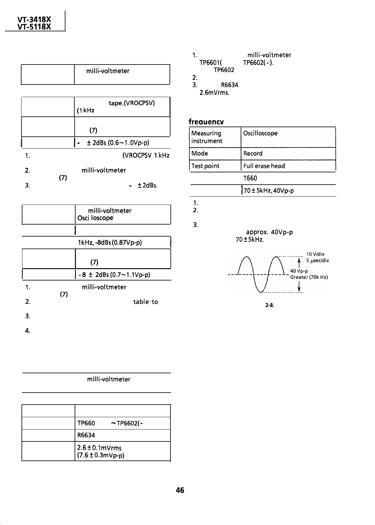
n
AUDIO CIRCUIT
Checking of audio play-back level
Measuring
instrument
Mode
I
Input signal
Test point
Specification
Playback the Alignment tape.
level adjusting signal)
Connect an AC
OUT (pin
Make sure that the output level is
AC milli-voltmeter
Playback
I
Alignment
kHz level adjusting signal.)
AUDIO OUT
(pin
of EL connector).
of EL connector)
9
to the AUDIO
9
Checking of audio record level
Measuring
instrument
Mode
I
Input signal
I
Test point
AC
I
Record/Playback
I
AUDIO OUT
(pin
of EL connector)
or
Connect an AC milli-voltmeter to test points
+ ) and
(Use
Set the unit in recording mode.
Adjust
for ground lead.)
so that the signal amplitude is
I
Checking of erase voltage and oscillation
I
Control
I
I
Specification
I
Put the unit in record mode.
Connect an oscilloscope across the full erase
head.
Make sure the erase voltage across the full
erase head is
frequency is
1
I
or greater
or more and
I
I
Specification
Connect an AC
OUT (pin
Feed the audio signal shown in
AUDIO IN jack.
Make the self-recording and playback of the
signal.
Make sure that the AUDIO OUT level is as
specified. If it is out of specified value, verify
the bias current (ADJUSTMENT OF AUDIO BIAS
CURRENT below).
of EL connector).
to the AUDIO
Adjustment of audio bias current
Measuring
instrument
I
Mode
I
Input signal
Test point
Control
Specification
AC
Oscilloscope
I
Record
I
Not required
0.3mVp-p)
or
TP6602(
)
the
.
I
Figure 2-8.
I
I
Page 47
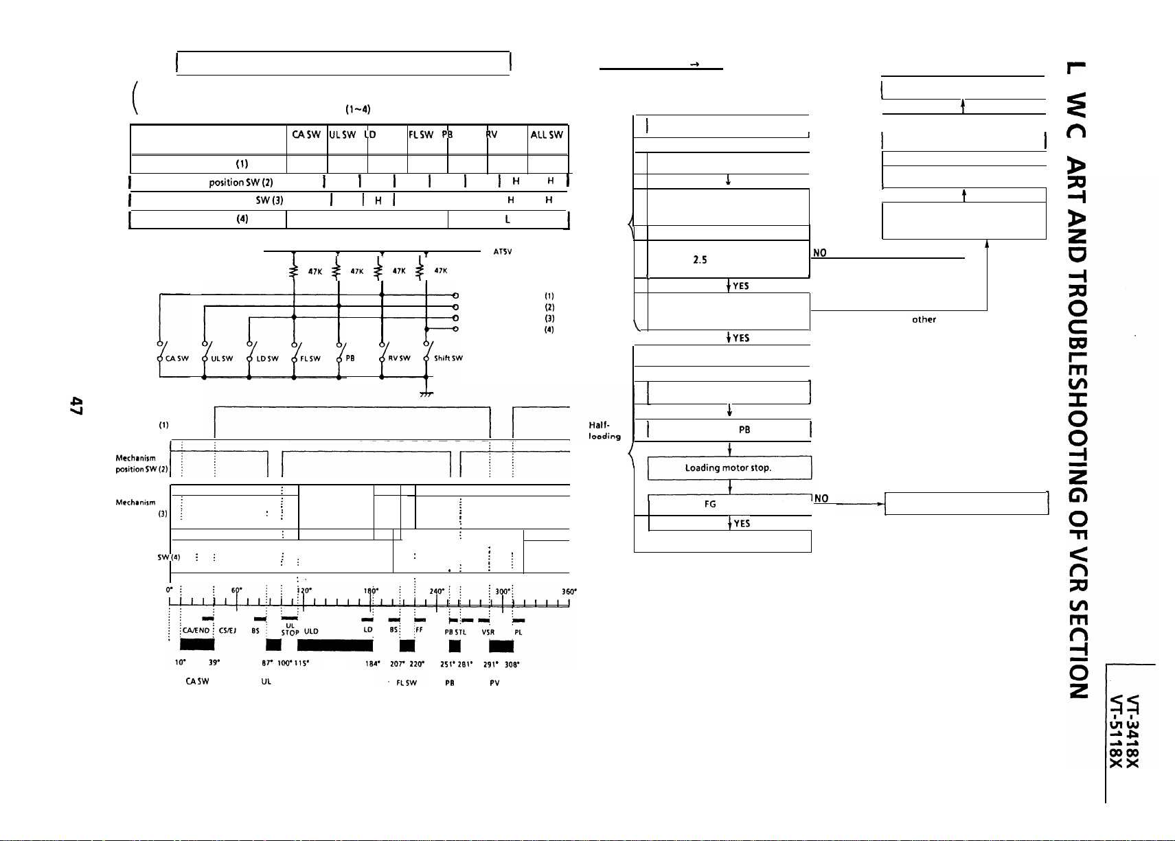
MECHANISM OPERATION FLOWCHART
l This flowchart describes the outline of the mechanism’s operation, but does not give its details.
l Function of cam switch bit reading.
The on/off of cam switch is cam position switch
‘ON’
Mechanism position SW (1) input
Mechanism position
Mechanism position SW
input
L
input
input
H H H
H
input signals in conditions as shown in below.
SW
‘ON’ ‘ON’
H H H H
L
H
H
‘ON’
H
SW
SW
‘ON‘
L I
L I L I H I
‘ON’
L
L L
I
‘OFF’
H
I
H
CASSETTE INSERTION -+ STOP
I
Turn off cassette switch.
Loading motor starts in normal
Cassette
direction and master cam clockwise.
inserting
Does cassette control clutch come
off within 2.5 sec. after cassette
switch has turned off?
Insert cassette.
t
I
t
End
I
I I
,
I
Cassette is ejected and loading
motor stops.
t
Cassette switch turns on.
Loading motor turns in reverse
direction and master cam
counterclockwise.
t
(Cassette is judged caught halfway.)
n
0
I
J
1
I
I
1
I
Mechanism
position SW (1)
position SW
Mechanism
position
CAM SW
h
.
:
:
: :
. .
.
,
: : :
: : :
:
:
:
. : :
. .
: :
. .
CD SW
SW
: : :
. ,
: :
:
. Shift zone
: :
: .
:
Mechanism position SW
Mechanism position SW (2)
Mechanism position SW (3)
Mechanism position SW (4)
. .
. .
: :
:
:
:
:
:
. .
: :
: .
: :
: :
.
: :
. .
: :
SW
SW
input
input
input
Input
Are start/end sensors at low level
before cassette insertion?
I
Drum motor starts.
t
Pinch roller comes into contact.
Cam switch is at
Is drum
I
position.
pulse outputted?
End
NO
(Cassette LED or some
judged defective.)
I
part is
Unloading
Page 48

STOP
PLAY
STILL
Picture appears.
t
Is take-up reel sensor signal
outputted?
PLAY
Press
key.
Set capstan motor to search
speed.
t
t
End
Slow brake
pressing
Slow brake comes into
Loading motor stops
Capstan motor stops.
End
STOP
Press STOP key.
I
Stop capstan motor.
Press
I
Pinch
roller
releasing
Idler
swinging
I
Release
Camswitchis;tPUposition.
,
Stop
Turn capstan motor in
reverse direction.
I
Stop
Is take-up reel sensor signal
outputted?
I
key.
roller.
motor.
motor.
to search
I
Loading motor turns in
reverse direction and master
I
I
I
Unloading
I
Page 49

STOP
Press
I
key.
I
STOP *CASSETTE EJECT
Cassette control clutch is engaged by pinch roller lever.
t
Cassette is ejected.
I
Brake
function
I
,
Cam switch
Stop loading motor.
I
Stop capstan motor.
Release brake solenoid and
brake reel disk.
.
t
End
STOP
Press STOP key.
t
t
End
Tape
unloading
Capstan motor turns in reverse direction
I
Cam switch is at
Stop position.
t
Cassette
ejection
1
1
switch is on.
Stop loading motor.
Stop capstan motor.
1
Stop drum motor.
t
I
Brake
latching
Tape
slack
I
I
Loading motor turns in reverse direction and master cam
Energize brake solenoid.
Cam switch is at
Turn loading motor in normal direction.
Cam switch is at UC stop position.
Is take-up reel pu-Ire outputted?
Release brake solenoid and brake reel disk.
clock wise.
Turn capstan motor in reverse direction.
position.
Stop capstan motor in about 5 sec.
I
Page 50

MECHANISM TROUBLESHOOTING
I
FAILURE(N0 TAPE WINDING)
Remove cassette
controller, turn
I
REVPLAY FAILURE (MODE RELEASE)
I
Remove cassette
I
reel disk
Is
motor turning?
gear in
I--
Tape travel is
presumably
overloaded due to
damage on tape.
Damaged tape is to
be out of use.
Are
and
applied ?
Replace capstan
motor.
YES
I
Check for broken
solenoid lead (turn
power off,
disconnect
check with tester).
t
Replacesolenoid.
and
I
Disconnect and
reconnect
while attracted, or
broken
lead)
1
Is brake shifter at
PLAY (MC)
position?
YES
brake shifter at
NO
Replace relay
shifter.
I
Is take-up reel disk NO
pulse outputted
H
Is
motor turning ?
YES
sensor.
I
Are
applied ?
and
NO
H
Disconnect and
reconnect main
Page 51

WINDING FAILURE AT
UNUSUAL SOUND
IN EACH MODE
Remove cassette
controller, turn power
on and press PLAY key.
Is take-up normal
during playback
Press
take-up reel disk by
hand.)
Y
Is brake shifter at
position
YES
NO
key. (Turn
NO
Replace brake
shifter.
Insert cassette and press
play and STOP keys
repeatedly.
Y
Is rattling sound heard
during loading/
unloading
YES
Turn power off and remove
cassette controller.
Is reel disk height as
specified (using jig)
Power ON
key IN
Is unusual sound heard at
NO
Press REW key and turn
take-up reel disk by hand.
Is unusual sound heard at
7
I
NO
Replace L block
assembly.
loading block)
,
Turn take-up reel disk
YES
YES
slowly with finger. Are
take-up reel stopper and
gear rubbing each
other ?
Is unusual sound heard
with capstan
running
block
YES
Undo reel belt, turn take-up
disk by hand and press
motor
NO
YES
J
key.
If there is no unusual
sound heard again in
each mode, go back to
the start of routine to
recheck.
I
L
and down. Is there
NO
Replace supply reel disk.
I
I
Page 52

VCR POWER
The VCR
FLOW CHART NO. l-l
KEY-IN
Key-h Input is not received.
I
FLOW CHART NO. 1-2
I
Unplug the AC power cord.
it a few minutes later.
I
IS the fuse
mother
I
Are the
normal in the VCR
Is the AT
Are the
properly connected with
Is there oscillation at pins (31) and
of
I
I
YES
and
line normal ?
and
YES
YES
in the TV
lines
lines
?
t
Does pin
from
the AC cord is plugged in or ALL
CLEAR button is pressed and
released?
the power button is pressed
to
of
to
IS
the PC
IS
the PC
of
change
L
level when
YES
1
e
level w
en
YES
-NO
line normal
YES
line normal ?
YES
Is the key switch in good contact 7
I
I
NO
NO
?
I
I
NO
NO
NO
I
I
I
.
Replace the fuse
Check the AT
Replace
Check pin
Check power key input to
and serial dataslclocks between
in
line,
and
Check poor soldering.
and /or
of
or
and
of connector
Check Q9903.
an
I
I
I
I
short-circuit in the key
the set
?
.
YES
of
YES
and signal
serial clock and
I
YES
of the
YES
?
YES
or
YES
and signal
serial clock and
of
when
INFRARED R/C
No operation is possible from the
infrared remote control.
I
Are signals received at pin
and pin
the key is activated
Check
of serial
:eady(L).
Does the infrared remote control
function ?
Is
applied at pin
remote control receiver ?
I
away from
Is there short-circuit in the key
input or
Check
line of serial
ready
NO
1
I
NO
NO
Check the switch contact.
Check
soldering.
I
lines to input
Replace the infrared remote
control as required.
Check the
I
Check pin
Reposition the set not to be
exposed to strong light.
Check key input terminals.
and switches for poor
FLOW CHART NO.
I
and
of
or
lines.
and /or
I
1
I
,
Check wire harness to mechanism.
I
I
Page 53

CASSETTE CONTROL
A cassette tape is not taken in.
I
t
the cassette housing in shape?
I
Are the cam switch and cassette
slider properly positioned ?
I
cassette tape is inserted ?
Does of
go to
cassette tape is inserted ?
when the cassette tape is inserted ?
I
YES
YES
level when the
of
YES
go to 1lV
I
FLOW CHART NO.
I
J
NO
I
I
J
Check the cassette switch and all .
Check the cassette housing.
I
Reposition the cam switch.
the way up to pin
Check
to pin
of
I
Check
of
and all the way up
J
I
J
I
Does the capstan motor start
when the EJECT button is pressed
Does the take-up reel disk turn
when the capstan motor is
running
reel
socket when theta e-up reel disk
is turning ?
Is pulse at pin
the take-up reel disk is turning
inputted
LOADING MOTOR AND EJECT
Acassette tape fails to eject.
t
YES
YES
at pin
YES
of
YES
of
when
NO
NO
ND
FLOW CHART NO.
I
I
See FLOW CHART NO. l-7.
Check the reel disk and reel drive
Check the reel sensor.
Check between pin
socket and all the way up to
and
Check between pin
and all the way up to pin
of
of
of
A cassette tape is taken in, but ejected at once.
f
Do start/end sensors voltage at
I(8) of
. to
L
when the cassette tape is loaded ?
Does cassette switch voltage at pin
of
to
to
cassette tape is loaded
I
I
Replace
level
change from
e from
when the
Is
Is the correct voltage at the
loading motor terminal ?
.
ND
ND
I
Check the start
Check the cassette switch and all
the way up to
end sensors and
Does the loading motor run?
Replace the cassette cam, gear,
etc.
of
YES
YES
NO
NO
NO
Check
of it.
Check between
the way up to the loading motor.
Replace the loading motor.
and
level of pin
all
Page 54

18X
U
J
Page 55

TAKE-UP REEL PULSE GENERATOR TROUBLESHOOTING
No reel sensor pulse appears.
I
I
FLOW CHART NO.
DRUM MOTOR TROUBLESHOOTING
The drum motor fails to run.
I
FLOW CHART NO.
I
NO
NO
Check
Check between the MC socket
and
socket and \C880
.
and between the MC
Check the
I
line.
Is there the reel sensor
pulse at pin (13) of the
connector EA ?
NO
Is there the reel sensor
pulse at pin (3) of the
connector
Replace the reel sensor
(located in the reel
sensor
?
NO
YES
Check the harness
Is pulseatof
Is
H l voltage at pin
socket
Replace the drum motor.
of ME
YES
The drum motor runs only for a few seconds.
I
I
,
HEAD SWITCHING PULSE
No head switching pulse.
I
Is
rotating ?
Are the drum
drum
to pins
YES
and
signal inputted
and
of
NO
I
,
YES
FLOW CHART NO.
See FLOW CHART NO.
pulse.
,
Is drum
ME socket 7
Is drum PC signal at pin
IS pulse at pin
signal at pin
YES
YES
of
of
of
NO
NO
Check between the ME socket
NO
Check the drum motor.
,
and pin
of
Check
Page 56

DRUM SERVO TROUBLESHOOTING
FLOW CHART NO.
NO
Check pin (4) of the
harness ME and the
drum motor.
In
Drum servo
Is there 8MHz
oscillation at ins
and
mode
Is there the
,
Is there the head
switching pulse at pin
Is there the drum
control
to pin
ME?
Check and replace the
drum motor.
of
not function.
3
of
YES
pin
?
YES
e applied
oft
e harness
YES
of
NO
.
?
NO
NO
I
amplifier circuit of
Check
and
See FLOW CHART NO. l-l
Does the drum error
(pins
and
operate normally ?
NO
in
Is there the reference
YES
signal (V-sync. ) at pin
of
Check the composite
sync. signal at pin (1) of
connector El from Y/C
I
mode
?
NO
I
Replace IC880
Check
I
Page 57

CAPSTAN SERVO TROUBLESHOOTING
Capstan servo does not function.
I
I
OW CHART NO.
Does
t
appear at pin 62) of
Is the harness EO-MR
normal ?
I
t YES
YES
YES
NO
Replace the harness
MR.
Replace
Check
YES
Check the composite
sync. slgnal line and pin
circuit.
Page 58

VCR RECORDING MODE
No record.
FLOW CHART NO.
VCR RECORDING MODE (CHROMA) TROUBLESHOOTING
Record Is In black and white ( E-E color mode
FLOW CHART NO.
I
Is there a signal at pin (32)
Is there a signal at pin (2)
of connector
Is there a signal at pin
of
Is pin
level
Check cylinder.
of
YES
YES
Are there
clock signals at pins (9) and
YES
Is there a signal at pin
I
Is there a signal at pin
I I
Is there a signal at pin
J
NO
l
I
Check the BIAS
line.
I
I
I
,
of
YES
of connector
YES
t ,
and
of
YES
7
NO
I L
NO
I
NORMAL
I I
Is there
Check pin
CC and signal line.
I
Check the signal at pin
(Frequency,
Frequency, 3.58 MHz.
of
of
of
DATA and
respectively?
at pin
YES
of connector
?
NO
and .
ABNORMAL
I-I I
Check
and peripheral circuit.
Check data and clock
signals from
Check the PC
Check
peripheral circuit.
Check the
Check the CHROMA
ROTARY line.
and
harness.
L
t
line.
Replace
I
I
I
I
Page 59

VCR PLAYBACK MODE (LUMINANCE)
No Playback.
VCR PLAYBACK MODE
Playback is in black and white.
I
I
FLOW CHART NO. 1-16
Are there at pin
of
YES
I
YES
t
Is there a
of
I
1 ?
YES
at pin
I
I I
Are there
clock signals at pins (9) and
Check
of
DATA and
respectively?
?
YES
Head
circuit of
I
YES
Check the harness from
I
the pin
level ?
YES
of
YES
I
I
NO
NO
H
NO
Check data and clock
signals from
Check the PC 5V line.
GOOD
Q2202-
I
Check
I
Replace
J
signal line.
Are there
clock signals at pins (9) and
I
Is there a signal at pin
of
I
I
Is there a
Is there a
of
of
YES
YES
?
YES
at pin
at pin
NO
NO
Check all the way up to
pin
the harness from
Check and adjust VCO
Is there
signal at pin
Check the signal at pin
of
of
toiCE
?
of
Replace
DATA and
respectively?
YES
and
rotary
of
YES
?
,4.43
I
Check DL550 1 and Q55
(PAL),
NO
Check the
ROTARY line.
ABNORMAL
peripheral circuit.
1
and Q5513,
and
Is there a chroma signal
at pin (5) of CC
connector
I
I
Check Q230 1 and
harness from
YES
EL J to
NO
I
I
Page 60

there a signal at pin
t
of
YES
of
,
?
YES
r
Is there a signal at pin
J
NO
NO
VCR E
E MODE
NO E-E signal.
Check the harness from
I
Is there
and
at pins
of
1 ?
AD
NO
to
EL
and input signal line.
FLOW CHART NO. 1-17
Sound is not heard >
I
Check the ‘L” level at
in
VCR SOUND
I
Is there Bias Oscillator
signal at pin
pin
Oscillator) ?
Check the
line between pin
of
Head.
No Sound
But audio
of
YES
Signal
and Audio
Sound is heard
and
(Bias
is not
FLOW CHART NO.
Sound is not heard
Is there an Audio
Signal at pin
?
of
NO
clock signals at pins
and
of
Replace
signals from
Replace
Check pin (19) of
parts.
I
Signal at pin
connector?
I I
Check the
TV mother
I
YES
of
YES
and peripheral
Check Q6602,Q6601 and peripheral parts.
I
I
Check the Audio mute circuit;
and
(TDA7233) on the
Check the
mode.
I
level at
I
and Q6607.
Page 61

TROUBLESHOOTING OF TV SECTION
I I
I
.I
ii
E
Page 62

Circuit to be checked:
TUNER
control
power source
NO PICTURE, NO SOUND
I
I
t
Does the noise level increase at max
Contrast, Brightness, and Sound Control ?
FLOW CHART
FLOW CHART NO.
NO
I
SCAN
1
Check the tuner bias.
t
I
Normal
I
I
I
t
Abnormal
t
Is there a
signal at
pin (7) of
1
Does the 9V
appear at pin (9) of
+ 6)
Is there a
signal at
t
Check
and
adjacent
parts.
bias check.
0
check
Normal
I
bias
I
I
I
parts.
I
I
Page 63

AND WHITE
FLOW CHART NO. 1-8
mode)
FLOW CHART NO.
I
NO SOUND
I
Circuits to be checked:
IC1801 and its
l
Output Circuit
,
NO SPECIFIC COLOUR (PAL)
Specific colours are not produced in
of
.
and at pin
there a
at pin
pin (3) of AD?
signal
Check the VCR:
TROUBLE SHOOTING
No
‘RECORD IS IN
I
Check
adjacent parts
and
Check speaker.
NO PLAYBACK PICTURE
I
NO PLAYBACK SOUND
FLOW CHART NO.
FLOW CHART NO. Z-7
(PAL
Check Q851 and its
adjacent circuits.
The picture colour is
I
adjacent circuits
Readjust the white
balance.
The picture
I
is
I
Page 64

Circuits to be checked:
l IC1801 and its Adjacent
Circuit
Output Circuit
NO SPECIFIC COLOUR (SECAM)
IS there a chroma signal at pin (20)
of IC1801
YES
No
and at
FLOW CHART NO. 1-9
Specific colours are not produced in
No
YES
Circuits to be checked:
l
and its Adjacent Circuit
l
8. Output Circuit
NO SPECIFIC COLOUR (NTSC)
,
Specific colours are not produced in
Is there a
at pin
of
and at pin
signal
pin (3) of AD?
Yes
receptron.
Check the VCR:
TROUBLE SHOOTING
No
‘RECORD IS IN
FLOW CHART NO.
mode)
When change channel No
does colour appear?
YES
YES
----
Check
Check
of connector
abnormal colour.
Check Pins
Abnormal
Signal
level at pm (9)
AG
in
t
When colour control minimum,
No
I
t
I
of
bias.
I
YES
No
I
i
Re-adjust the
white balance. I
X1801 (NTSC
Check
adjacent circuits.
_
1401
and its
I
adjacent circuits
I
Readjust the white
balance.
Check
I
adjacent circuits.
I
and its
I
I
I
I
Page 65

MODEL
FULL ERASE HEAD
OVERALL SCHEMATIC DIAGRAM
L---_---J
I
1
I
2
I
3
I
4
I
5
I
6
I
Page 66

TV MAIN
2
3 3
.
6 6
I
7
638PEZZ
7
I
8
I
9
I
I
I
I
Page 67

I
I
MODEL VT-51
FULL ERASE HEAD
OVERALL SCHEMATIC DIAGRAM
DRUM MOTOR UN
1
I
2
I
3
I
4
I
5
I
6
Page 68

7 z
4
I
7
I
4
5
I
8
I
9
I
I
I
1
Page 69

MODEL
H
G
F
E
[G-DRIVE]
CHASSIS LAYOUT OF TV SECTION
I
K
H
0
0
0
I
0
cl
D
C
0
I
l
--
B
A
.
Page 70

B-A ,
VIDEO IN
AUDIO IN
L
IL-
L
cl
l
I
7
AD
3
I
8
I
9
I
I
I
1
Page 71

MODEL VT-51
H
G
F
CHASSIS
K
UT OF TV SECTION
E
D
C
I
r
B
I
UP
I
I
I
I
A
1
I
2
I
3
0
I
4
I
AU
5
0
I (VIDEO)
I
6
Page 72

18X
VIDEO IN
7
J
, \
AUDIO IN
I I
.
DA
I
0
0
0
1
a
XI
I
0
1
3
0
0
L-l
n
AD
1
3
l
I
7
I
8
9
I
I
I
Page 73

MODEL
Mother Unit
H
G
F
BLOCK DIAGRAM OF TV SECTION
E
D
C
I
PHOTO
.
A
1
I
2
I
3
I
4
I
5
I
6
I
Page 74

UNIT
7
I
8
I
9
I
I
I
Page 75

MODEL
Mother Unit
18X BLOCK DIAGRAM OF TV SECTION
r
t i
,-
I
1
I
2
I
3
I
4
I
5
I
6
Page 76

UNIT
I
7
I
8
I
9
I
I
I
1
Page 77

MODEL
BLOCK DIAGRAM OF TV SECTION
Cl CRT Socket, Power SW, R/C, Line Filter,
AN Unit
----HER,
1
I
2
I
3
I
4
I
5
,
I
6
I
Page 78

VIDEO
CHROMA
JUNGLE
7
I
8
I
9
I
I
I
I
Page 79

I
MODEL
CRT Socket, Power SW,
H
G
F
BLOCK DIAGRAM OF TV SECTION
R/C,
Line Filter,
AN Unit
E
D
C
B
A
-- -z
-----
E
1
2
I
3
I
4
I
5
I
6
Page 80

I 1
VIDEO
CHROMA
JUNGLE
r
I
7
I
8
I
9
I
I
I
I
Page 81

MODEL
BLOCK DIAGRAM OF TV SECTION
Sound Output Unit
H
G
F
E
D
C
B
A
1
I
2
I
3
I
4
I
5
6
Page 82

DESCRIPTION OF TV SECTION
SCHEMATIC DIAGRAM
I
DISCONNECT THE AC PLUG FROM THE AC OUTLET BEFORE
REPLACE/NC PARTS.
SEMICONDUCTOR HEAT SINKS SHOULD BE REGARDED AS
POTENTIAL SHOCK HAZARDS WHEN THE CHASSIS IS
OPERATING.
BE SURE TO USE GENUINE PARTS FOR SECURING THE SAFETY
AND RELIABILITY OF THE SET.
PARTS MARKED WITH
FOR MAINTAINING THE SAFETY OF THE SET.
REPLACE THESE PARTS WITH SPECIFIED ONES FOR
MAINTAINING THE SAFETYAND PERFORMANCE OF THE SET.
SERVICE PRECAUTION:
THE AREA ENCLOSED BY THIS LINE
DIRECTLY CONNECTED
WHEN SERVICING THE AREA, CONNECT AN ISOLATING
TRANSFORMER BETWEEN TV
HAZARD OF ELECTRICSHOCK.
CAUTION:
This circuit diagram is original one, therefore there may be a
slight difference from yours.
NOTE:
NOTICE:
VOLTAGE.
ARE IMPORTANT
BE SURE TO
IS
LINE TO ELIMINATE
NOTES:
The unit of resistance “ohm
resistors are
ohms,
M =
watt, unless otherwise
is omitted.
ohm).
no ted.
The unit of capacitance
=
is omitted.
The values in parentheses are the ones in the
mode; the values without parentheses are
the ones in the
VOLTAGE MEASUREMENT CONDITIONS:
DC voltages are measured between points
indicated and chassis ground by
AC 1
supplied to unit and
with
controls are set to normal viewing picture
unless
Voltages are measured with
noted.
B&W of
signal.
WAVEFORM MEASUREMENT CONDI-
TIONS:
87.5% modulated co/our bar signal
is fed into tuner.
Page 83

WAVEFORMS
MOTHER MOTHER
0
4
vp-p
MOTHER
0
9
18x
MOTHER
0
3
MOTHER
0
8
,
I
L
MOTHER
0
2
MOTHER
0
7
VP-P
.
MOTHER
0
1
MOTHER
0
6
MOTHER MOTHER MOTHER MOTHER
VP-P
. .
. .
5
VP-P
0
MOTHER
0
MOTHER
0
MOTHER
0
0
CRT
0
CRT
(kt) VT-5118X
0
18X
0
CRT
0
0
Page 84

SOLID STATE DEVICE
6 4
3
1
SIDE VIEW
BASE DIAGRAM
C E
1
BASE
COLLECTOR
BASE
L
COLLECTOR
EMITTER
0
BASE
L
COLLECTOR
EMITTER
.
0
BASE
COLLECTOR
EMITTER
0
1
9
CE
7
Page 85

MODEL
SCHEMATIC DIAGRAM
Mother Unit
H
G
F
E
3
D
C
A
1
I
2
I
3
I
4
I
5
I
6
Page 86

7
I
8
I
9
I
I
I
I
Page 87

MOD
n
Mot
H
G
F
Unit-l
SCHEMATIC DIAGRAM
E
D
C
B
A
1
I
2
I
3
I
4
I
5
6
.
Page 88

J
I
r
TUNER
Page 89

n 3
Page 90

AV UNIT
I
I I
I
7
I
8
I
9
I
I
I
Page 91

MODEL
n
CRT Socket, Power SW, R/C, Line Filter,
I WEV I
SCHEMATIC DIAGRAM
AN Unit
I
--
1
I
2
I
3
I
4
I
5
I
6
Page 92

,
I
I
7
I
8
I
9
I
I
I
Page 93

MODEL
n
CRT Socket, Power SW, R/C, Line Filter,
I
SCHEMATIC DIAGRAM
AN Unit
e---v----!-l
I’
1om
I I
I
I
1
I
2
3
I
4
I
5
I
6
Page 94

7
I
8
I
9
I
I
I
I
Page 95

I
W
I
I
m
I
n
I
A
I
T
S-ATT
ICE
6
4
mm
I
2
+
5
TO
+
I
TO
NO74 ICE
4
,
.
T
ICE
Page 96

n
Tuner
NOTE: The parts here shown are supplied as an assembly but not independently.
. . . . . . . . . .
. : : : . . . : : : . . . . . : : : . .
. .
. : : . :
. . . . . . . . . . . . . . . . . . . . . . .
I
I
l
Infrared Remote Control Unit
NOTE: The parts here shown are supplied as an assembly but not independently.
AFT
I
1
I
2
I
3
I
4
I
5
6
Page 97

D
I
I
n
I
I
m
I
n
I
I
Page 98

Memo
. . . . . . . . . . . . . . . . . . .
. . . . . . . . . . . . . . . . . . . . . . . . . . . . . . . . . . . .
. . . . . . . . . . . . . . . . . . . . . . . . . . . . . . . . . . . . . . . . . . . . . . . . . . . . . . . . . . . . . . . . . ..*.........
. . . . . . . . . . . . . . . . . . . . . . . . . . . . . . . . . .
. . . . . . . . . . . . . . . . . . . . . . . . . . . . . . ..a.....
. . . . . . . . . .
. . . . . . . . . . . . . . . . . . . . . ..*......................................
. . . . . . . . . . . . . . . . . . . . .
. . . . . . . . . ..*...............
. . . . . . . . . . .
. . . . . . . . . . . . . . . . . . . . . . . . . . . . . . . . . . . . . . . . . . . . . . . . . . . . . . . . . . . . . . . . . . . . . . . . . . . . . . . . . . . . . . . . . . . . . . . . . . . . . . . . .
. . . . . . ..*...........................................*
. . . . . . . . . . . . . . . . . . . . . . . . .
. . . . . . . . . . . . . . . . . . . . . . . . . . . . . . . . . . . . . . . . . . . . . . . . . . . . . . . .
. . . . . . . . . . . . . . . . . . . . . . . . . . . . . . . . . . . . . . . . . . . . . . . . . . . . . . . . . . . . . . . . .
. . . . . . . . . . . . . . . . . . . . . . . . . . . . . . . . . . . . . . . . . . . . . . . . . . . . . . . . . . . . . . . . . . . . . . . . . . . . . . . . . . . . . . . . . . . . . . . . . . . . . . . . . . . . . . . . . . . . . . . .
. . . . . . . . . . . . . . . . . . . . . . . . . . . . . . . . . . . . . . . . . . . . . .
. . . . . . . . . . . . . . . . . . . . . . . . . . . . . . . . . . . . . . . . . . . . . . . . . . . . . . . . . . . . . . . . . . . . . . . . . . . . . . . . . . . .
. . . . . . . . . . . . . . . . . . . . . .
. . . . . . . . .
. . . .
. . . . . . . . .
.....................................................................................................
..............................................................................
............................................................................................
.....................................................................
..........................................................................................................................................................................
Page 99

CHASSIS LAYOUT OF VCR SECTION
JACK
I
Y
LEVEL
I
I
ALL C
I
Y
El
I
0
I
I
Et
EM
I
1
I
2
I
3
I
4
I
5
6
Page 100

,
W-CLIP
CLIP
DEVIATION
I
“Co
GND
0
l-l
.
PB CHROMA
HEAD SWITCHING PULSE
I
REC SIGNAL
0
I
I
0
0
ED
.
I
n
EL
I BIAS(+)
BIAS
I
I
0
I
9
I
I
I
cl
n
I
7
8
 Loading...