

Sharp VL-RDI U Service Manual
VL-RDl U
SHARI= SERVICE MANUAL
S58Q2VL-RDI U/
LIQUID CRYSTAL DIGITAL CAMCORDER NTSC
MODEL VL-RDI u
In the interests of user-safety (Required by safety regulations in some countries) the-set should be restored to its 1
original condition and only parts identical to those specified
be used.
/
- CONTENTS
1.
2.
3.
4.
5.
6.
7.
8.
9.
Page
IMPORTANT SERVICE NOTES . . . . . . . . . . . . . . . . . . . . . . . . . . . . . . . . . . . . . . . . . . . . . . . . . . . . . . . . . . . . . . . . . . . . . . . . ..*..*........................
l-l
SPECIFICATIONS . . . . . . . . . . . . . . . . . . . . . . . . . . . . . . . . . . . . . . . . . . . . . . . . . . . . . . . . . . . . . . . . . . . . . . . . ..~................................................
2-l
PART NAMES . . . . . . . . . . . . . . . . . . . . . . . . . . . . . . . . . . ..~.............................................................................................
3-l
DISASSEMBLY OF THE SET . . . . . . . . . . . . . . . . . . . . . . . . . . . . . . . . . . . . . . . . . . . . . . . . . . . . . . . . . . . . . . . . . . . . . . . . . . . . . . . . . . . . . . ..~................
4-l
MECHANISM ADJUSTMENT JIGS AND PARTS . . . . . . . . . . . . . . . . . . . . . . . . . . . . . . . . . . . . . . . . . . . . . . . . . . . . . . . . . . . . . . . . . . . . . . . ..~.
5-l
INSPECTION AND MAINTENANCE
ITEMS AND INTERVALS . . . . . . . . . . . . . . . . . . . . . . . . . . . . . . . . . . . . . . . . . . . . . . . . . . . . . . . . . . . . . . . . . . . . . . . . . . . . . . . . . . . . . . . . . . . . . . . . . . . . . . . . . . . . . . . .
6-1
MECHANICAL ADJUSTMENTS AND CHECKS
. . . . . . . . . . . . . . . . . . . . . . . . . . . . . . . . . . . . . . . . . . . . . . . . . . . . . . . . . . . . . . . . . . . . . . . . . . . . .
7-1
TAPE RUNNING ADJUSTMENT . . . . . . . . . . . . . . . . . ..*.................................................................................
8-l
MECHANICAL SECTION ASSEMBLY AND PARTS REPLACEMENT
(DISASSEMBLY AND REASSENBLY)
. . . . . . . . . . . . . . . . . . . . . . . . . . . . . . . . . . . . . . . . . . . . . . . . . . . . . . . . . . . . . . . . . . . . . . . . . . . . ..~............
9-l
1 O.ADJUSTlNG THE ELECTRICAL CIRCUITS
.................................................................................
IO-I
11 .USEFUL TIPS ................................................................................................................................
II-I
12.SIGNAL FLOW DIAGRAM
.............................................................................................................
12-I
13.BLOCK DIAGRAM ........................................................................................................................
13-1
14.SCHEMATIC DIAGRAM ................................................................................................................
14-1
1 SSEMICONDUCTOR LEAD IDENTIFICATION
...............................................................................
15-1
16.PRINTED WIRING BOARD ASSEMBLIES
“” 1 6-l
...................................................................................
17.REPLACEMENT PARTS LIST
....................................................................................................... 17-l
18.PACKING OF THE SET .................................................................................................................
18-I
SHARP CORPORATION
This document has been published to be used for
after sales service only.
‘\:
The contents are subject to change without notice.
VL-RDI U
1. IMPORTANT SERVICE NOTES
BEFORE RETURNING THE VIDEO CAMERA
RECORDER
Before returning the video camera recorder to the user,
perform the following safety checks.
1. Inspect all lead dress to make certain that leads are
not pinched or that hardware is not lodged between
the chassis and other metal parts in the video camera
recorder.
2. Inspect all protective devices such as non-metallic
control knobs, insulating materials, cabinet backs,
adjustment and compartment covers or shields, isolation resistor/capacitor networks, mechanical insulators etc.
connections, metal cabinet, screw heads, knobs and
control shafts, etc.) and measure the AC voltage drop
across the resistor. Reverse the AC plug (a non
polarized adaptor plug must be used but only for the
purpose of completing these checks) on the set and
repeat the AC voltage measurements for each exposed metallic part. Any reading of 0.45V rms (this
corresponds to 0.3mA rms AC.) or more is excessive
and indicates a potential shock hazard which must be
corrected before returning the video camera recorder
to the user.
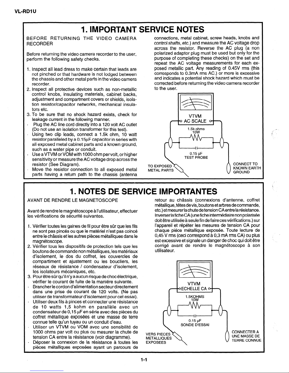
3. To be sure that no shock hazard exists, check for
leakage current in the following manner.
l Plug the AC line cord directly into a 120 volt AC outlet
(Do not use an isolation transformer for this test).
. Using two clip leads, connect a 1.5k ohm, 10 watt
resistor paralleled by a 0.151_1F capacitor in series with
ali exposed metal cabinet parts and a known ground,
such as a water pipe or conduit.
VTVM
0 AC SCALE 0 \
’ -5g000Gms
. UseaVTVMorVOMwithlOOOohmpervolt,orhigher
sensitivity or measure the AC voltage drop across the
resistor (See Diagram).
l Move the resistor connection to all exposed metal
parts having a return path to the chassis (antenna
METAL PARTS
1. NOTES DE SERVICE IMPORTANTES
AVANT DE RENDRE LE MAGNETOSCOPE
retour au chassis (connexions d’antenne, coff ret
m&allique, t&es devis, boutons et arbres de commande,
Avant de rendre le magnetoscope a I’utilisateur, eff ectuer
etc.) et mesurer lachutedetension CAentre la resistance.
les verifications de securite suivantes.
lnverserlaficheCA(uneficheintermediairenonpolarisee
doit etre utilisee a seule fin de faire ces verifications.) sur
1. Verifier toutes les gaines de fil pour etre sijr que les fils
I’appareil et &peter les mesures de tension CA pour
ne sont pas pin&s ou que le materiel n’est pas coin&
chaque piece metallique exposee. Toute lecture de
entre le chassis et les autres pieces metalliques dans le
0,45 V rms (ceci correspond a 0,3 mA rms CA) ou plus
magnetoscope.
est excessive et signale un danger de choc qui doit etre
2. Verifier tous les dispositifs de protection tels que les
corrige avant de rendre le magnetoscope a son
boutons de commande non metalliques, les materiaux
utilisateur.
d’isolement, le dos du coffret, les couvercles de
compartiment et ajustement ou les boucliers, les
reseaux de resistance / condensateur d’isolement,
les isolateurs mecaniques, etc.
3. Pour etre sur qu’il n’y a aucun risque de choc electrique,
verifier le courant de fuite de la maniere suivante.
VTVM
l Brancher le cordon d’alimentation secteur directement
dans une prise de courant de 120 volts. (Ne pas
oECHELiE CA 0 \
utiliser de transformateur d’isolement pour cet essai).
l Utiliser deux fils a pinces et connecter une resistance
de 10 watts I,5 kohm en parallele avec un
condensateur de 0,15 PF en serie avec des pieces du
coffret metallique exposees et une masse de terre
connue telle qu’un tuyau ou un conduit d’eau.
l Utiliser un VTVM ou VOM avec une sensibilite de
1000 ohms par volt ou plus ou mesurer la chute de
tension CA entre la resistance (voir diagramme).
METALLIQUES
l Deposer la connexion de la resistance & toutes les
pieces metalliques exposees ayant un parcours de
l-l

VL-RDl UJ
WARNING :TO REDUCETHE RISK OF FIRE OR ELECTRIC SHOCK, DO NOT EXPOSE
THIS APPLIANCE TO WET LOCATIONS.
A
I
0
CAUTION: TO REDUCE THE RISK OF ELECTRIC
SHOCK. DO NOT REMOVE COVER. NO
USERSERVICEABLE PARTS INSIDE.
REFER SERVICING TO QUALIFIED SERVICE
PERSONNEL.
This symbol warns the user of uninsulated
voltage within the unit that can cause dangerous electric shocks.
This symbol alerts the user that there are
important operating and maintenance instructions in the literature accompanying this unit.
CAUTION
This symbol mark means following.
For continued protection against fire haz-
ard, replace only with same type fuse.
(CPI ; 1.25A 24V, CP2; 1.25A 24V, CP3;
1.25A 24V)
Camcorder
only
All-ENTION: POUR REDUIRE LES RESQUES D’INCENDIE OU DE CHOC ELECTRIQUE,
NE PAS EXPOSER CET APPAREIL A LA PLUIE OU A L’HUMIDITE.
A
I
a
ATTENTION: AFIN DE REDUIRE LES RISQUES DE
CHOC ELECTRIQUE, NE PAS RETIRER LE
COUVERCLE, AUCUN ORGANE INTERNE
NE PEUT ETRE REPARE PAR
L’UTIUSATEUR, CONFIER L’APPAREIL A
UN DEPANNEUR QUALIFIE.
Ce symbole signale a I’utilisateur la presence
d’une tension non isolee a I’interieur de I’appareil
qui peut etre la cause de secousses electriques
dangereuses.
Ce symbole avertit I’utilisateur que des instructions importantes relatives a I’utilisation
et al’entretien se trouvent dans le manuel
accompagnant I’appareil.
ATPENTION
Ce symbole signifie que f’on devra uti- Camcorder
liser un fusible de meme type (CPl; seulement
1,25A 24V, CP2; 1,25A 24V, CP3; 1,25A
24V) pour assurer la securite.
1-2
VL-RDl U
/fj CAUTION
BEFORE BATTERY DESTROY
NICKEL-CADMIUM BAl-lERY
The following program is available in the United States. Please consult local environmental
authorities concerning the availability of this or other programs in your area.
The RBRCTM Seal
SHARP participates in the RBRCTM* Nickel-Cadmium Battery Recycling Program in the United
States. The RBRCTM Seal on our battery pack contained in our product indicates that SHARP is
voluntarily participating in an industry program to collect and recycle these batteries. The RBRCTM
program provides you with a convenient alternative to placing spent Nickel-Cadmium battery packs into
the trash or municipal waste stream, which is illegal in some areas. At the end of their useful life, the
Nickel-Cadmium battery can be dropped off at the nearest collection center for recycling. For information
on the nearest collection center, call I-800-8-BATTERY or your local recycling center. If you are located
outside the United States, contact your local authorities for information concerning proper disposal and/
or recycling of this battery. SHARP’s involvement in this program is part of our commitment to protecting
our environment and conserving natural resources.
[Footnote] *RBRCTM is trademark of the Rechargeable Battery Recycling Corporation.
.
NICKEL-METAL HYDRIDE BATTERY
LITHIUM or LITHIUM-ION BATTERY
SEALED LEAD BATTERY
Battery disposal
Contains the above (Rechargeable) Battery. must be recycled or disposed of properly.
Remove the Battery from the products and contact Federal or State Environmental Agencies for
information on recycling and disposal options.
1-3
VL-RDI U
2. SPECIFICATIONS
Signal System:
Recording System:
Cassette:
Recording/Playback Time:
Tape Speed:
Pickup Device:
Lens:
Monitor:
Minimum Illumination:
Video Output Level:
Audio Output Level:
Speaker Output:
Power Requirement:
Power Consumption:
Operating Temperature:
Operating Humidity:
Storage Temperature:
Dimensions (approx.):
Weight (approx.):
NTSC standard
2 rotary heads, helical scanning system
Digital VCR Mini DV video cassette
I
90 minutes (DVMGO, LP mode)
SP mode: 18.812 mm/second
LP mode: 12.555 mm/second
l/3” (8.5mm, effective size: 6.0) CCD image sensor (with approx.
660,000 pixels including optical black)
10 x power zoom lens (F1.8-2.6, f=4.2-42 mm), full-range auto focus, manual
focusing possible
3” (7.6 cm) -full-color LCD screen
5 lux (20 lux measured by EIA standard)(Fl.8, with gain-up and digital zoom off)
1 .O Vp-p 75-ohm unbalanced
- 8 dBs, impedance less than 2.2 kohms
300 mW
DC 7.2V
6.8W (during camera recording in full auto mode with zoom motor off backligt in
normal mode)
0°C to +4O”C (32°F to 104°F)
30% to 80%
- 20°C to +6O”C (-4°F to 140°F)
6 13/3$ (W) x 3 21/3$ (H) x 2 I/$’ (D) without lens hood and protruding parts
[I63 mm (W) x 93 mm (H) x 57 mm (D)]
1.2 Ibs (545 g) (without battery pack, lithium battery, video cassette and lens cap)
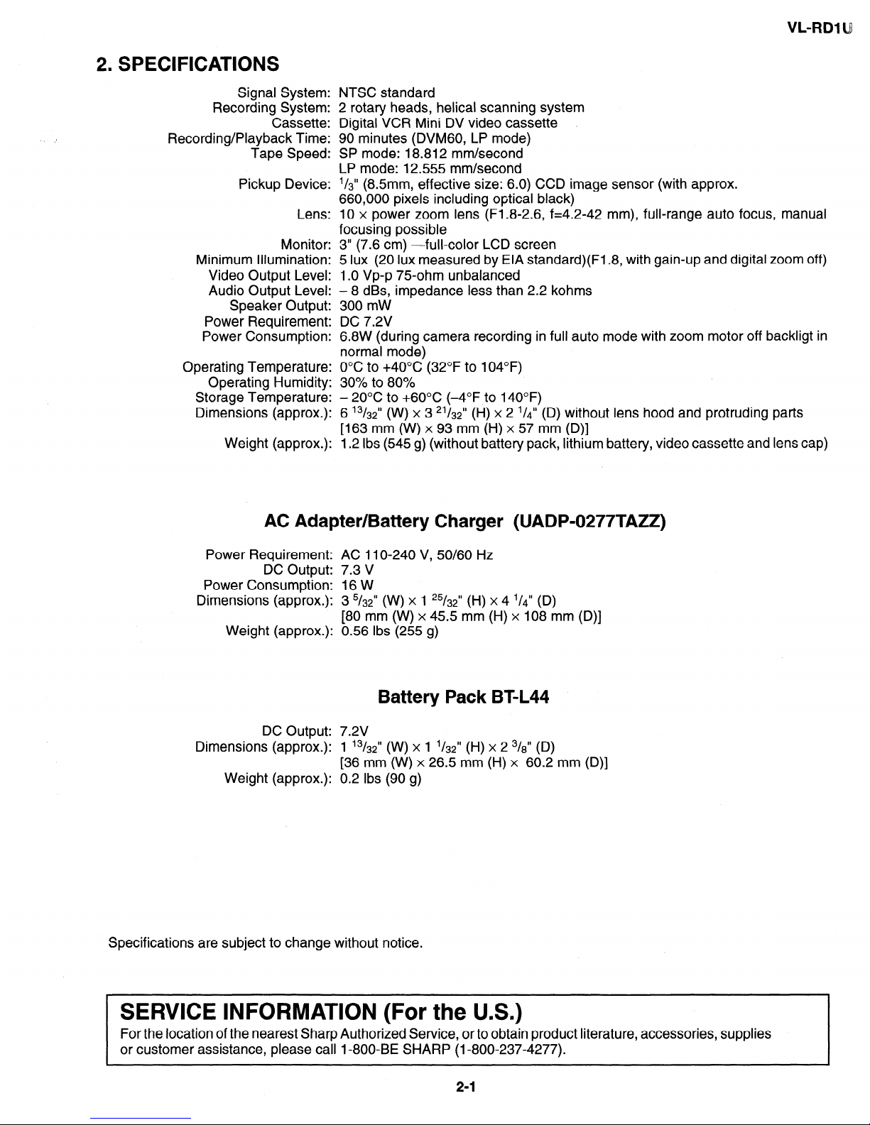
AC Adapter/Battery Charger (UADP-0277TAZZ)
Power Requirement: AC 11 O-240 V, 50/60 Hz
DC Output: 7.3 V
Power Consumption: 16 W
Dimensions (approx.): 3 5/32” (W) x 1 25/32” (H) x 4 l/d” (D)
[80 mm (W) x 45.5 mm (H) x 108 mm (D)]
Weight (approx.): 0.56 Ibs (255 g)
Battery Pack BT-L44
DC Output: 7.2V
Dimensions (approx.): 1 ‘3/32” (w) x 1 ‘/32” (H) x 2 3/$ (D)
[36 mm (W) x 26.5 mm (H) x 60.2 mm (D)]
Weight (approx.): 0.2 Ibs (90 g)
Specifications are subject to change without notice.
1 SERVICE INFORMATION (For the U.S.)
I
For the location of the nearest Sharp Authorized Service, or to obtain product literature, accessories, supplies
or customer assistance, please call I-800-BE SHARP (I-800-237-4277).
2-1
VL-RDl U
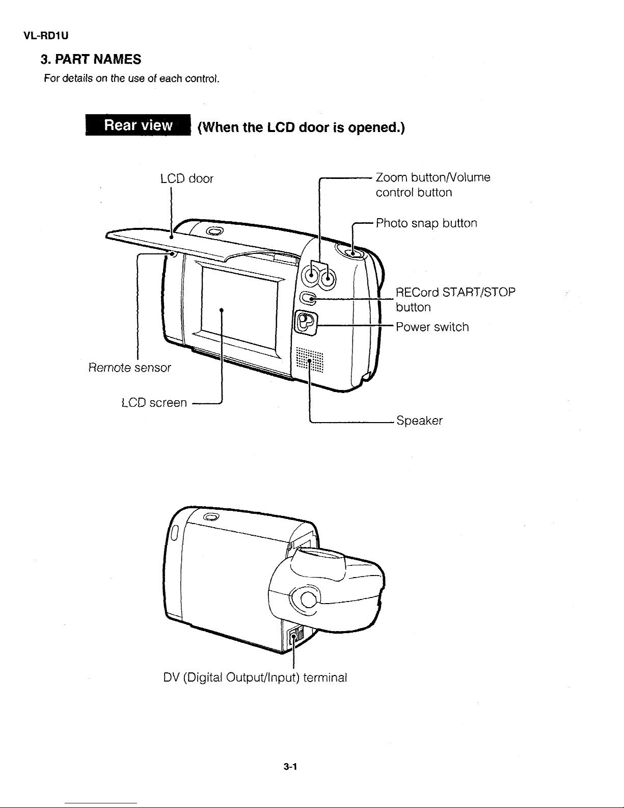
3. PART NAMES
For details on the use of each control.
Zoom button/Volume
Photo
snap button
RECord START/STOP
Remote sensor
DV (Digital Output/Input) terminal
3-1
VL-RDI
U
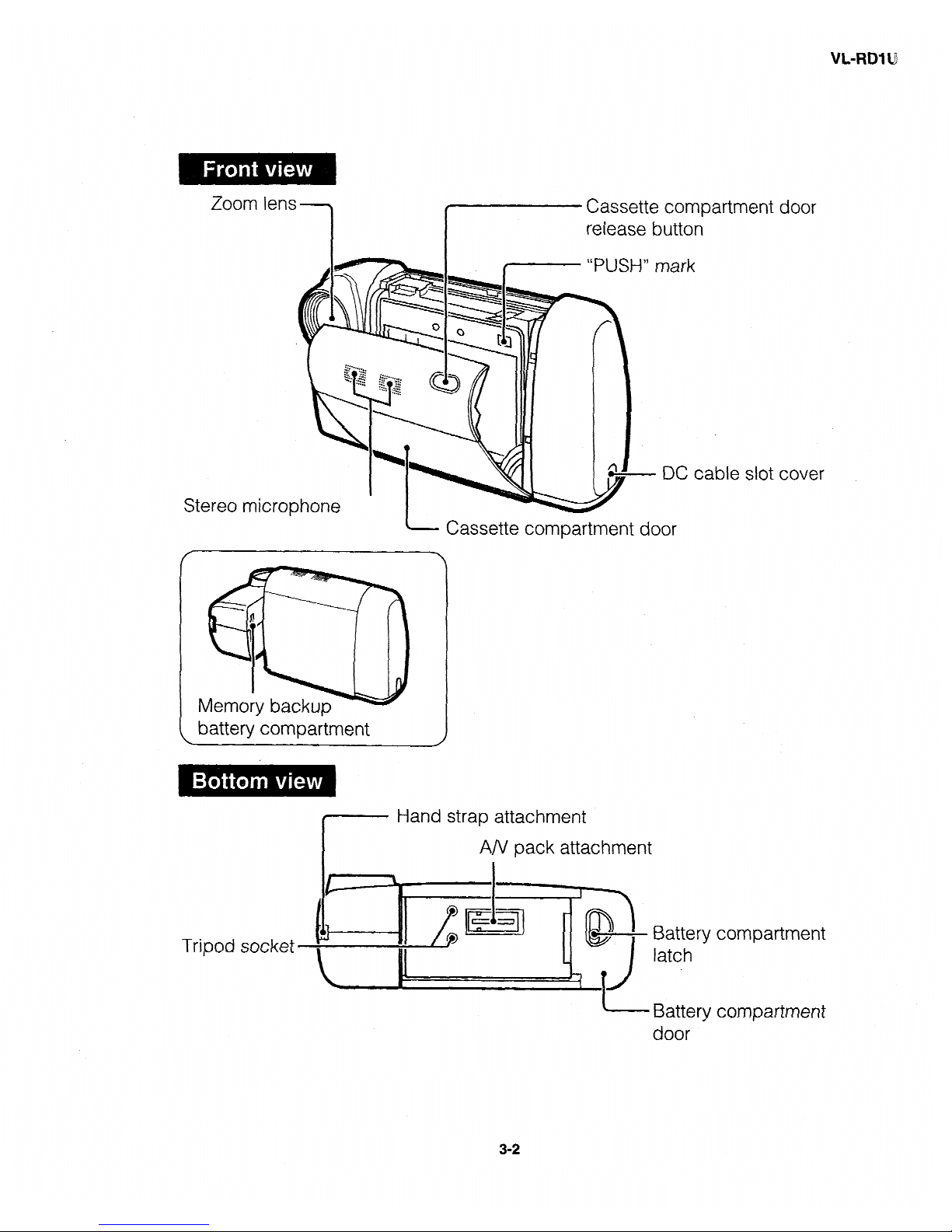
Zoom
Stereo
t-r
lens
1
micro
lark
DC
Cassette compartment door
partment door
1
cable slot cover
battery compartment
I----- Hand strap attachment
I
A/V pack attachment
Tripod socket
Battery compartment
latch
Battery compartment
door
VL-RDl U
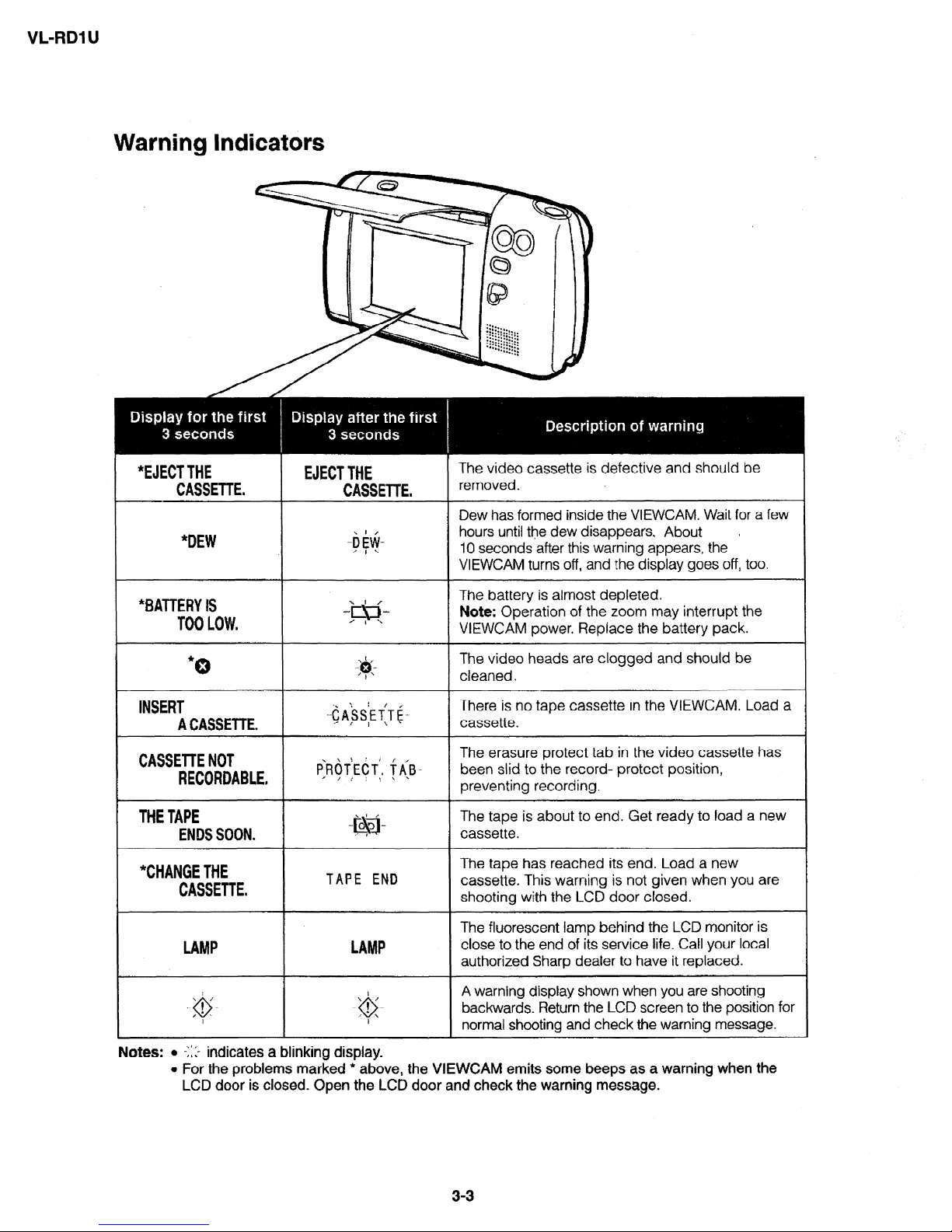
Warning Indicators
*EJECTTHE
EJECTTHE
CASSETTE.
CASSETTE.
The video cassette is defective and should be
removed.
*DEW
j Dew has formed inside the VIEWCAM. Wait for a few
hours until the dew disappears. About
I
IO seconds after this .warning appears, the
VIEWCAM turns off, and the display goes off, too,
*BATTERY6
TOOLOW.
/
-“Y!.!-
’ I L
The battery is almost depleted.
Note: Operation of the zoom may interrupt the
VIEWCAM power. Replace the battery pack.
*
0
The video heads are clogged and should be
cleaned.
INSERT
ACASSETTE.
There is no tape cassette in the VIEWCAM. Load a
cassette.
CASSElTENOT
RECORDABLE,
The erasure protect tab in the video cassette has
been slid to the record- protect position,
preventing recording.
THETAPE
ENDSSOON. (
The tape is about to end. Get ready to load a new
cassette.
"CHANGETHE
CASSETTE.
TAPE END
The tape has reached its end. Load a new
cassette. This warning is not given when you are
shooting with the LCD door closed.
LAMP
The fluorescent lamp behind the LCD monitor is
close to the end of its service life. Call your local
authorized Sharp dealer to have it replaced.
. . ’ 1
‘...
9
, l . .
.- ’ ; t._
0
:-
2
A warning display shown when you are shooting
backwards_ Return the LCD screen to the position for
normal shooting and check the warning message.
Notes: l -1: :.-
indicates a blinking display.
l For the problems marked * above, the VIEWCAM emits some beeps as a warning when the
LCD door is closed. Open the LCD door and check the warning message.
3-3
VL-RDl lJ
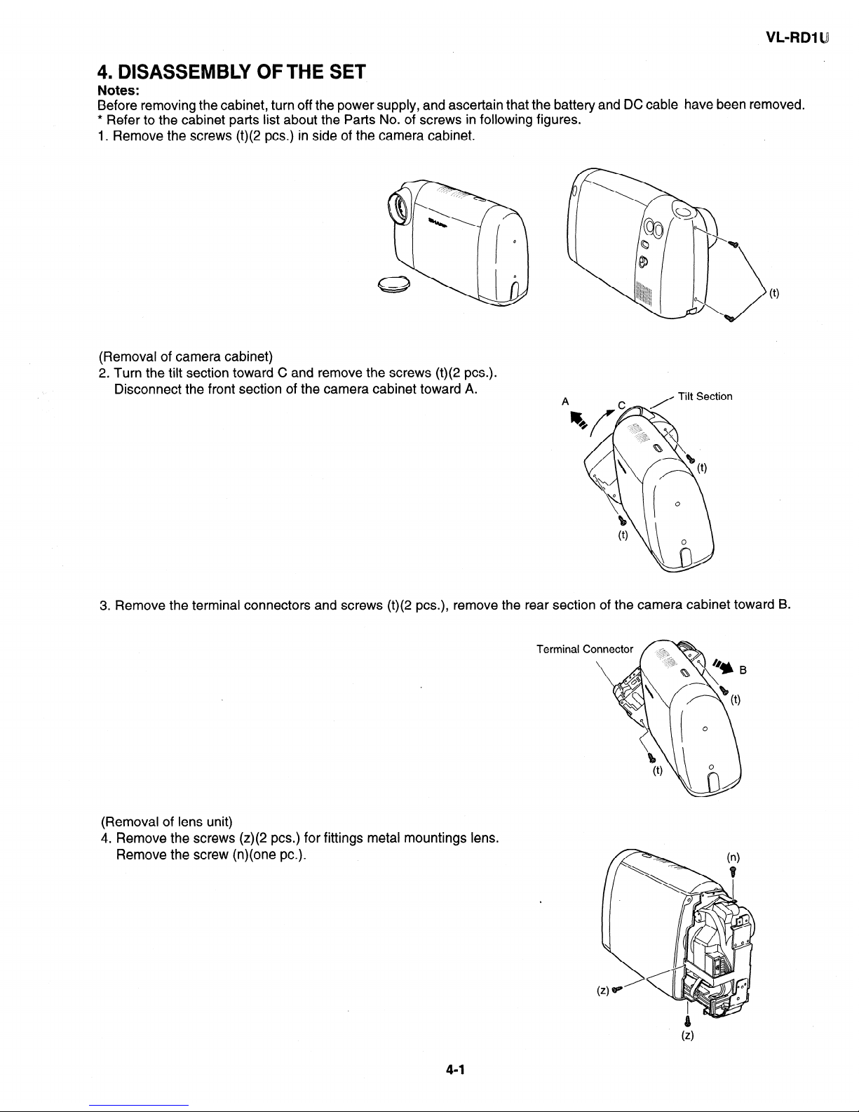
4. DISASSEMBLY OFTHE SET
Notes:
Before removing the cabinet, turn off the power supply, and ascertain that the battery and DC cable have been removed.
* Refer to the cabinet parts list about the Parts No. of screws in following figures.
1. Remove the screws (t)(2 PCS.) in side of the camera cabinet.
(Removal of camera cabinet)
2. Turn the tilt section toward C and remove the screws (t)(2 PCS.).
Disconnect the front section of the camera cabinet toward A.
(0
3. Remove the terminal connectors and screws (t)(2 PCS.), remove the rear section of the camera cabinet toward B.
Terminal
(Removal of lens unit)
4. Remove the screws (z)(2 PCS.) for fittings metal mountings lens.
Remove the screw (n)(one PC.).
4-1
VL-RDl U
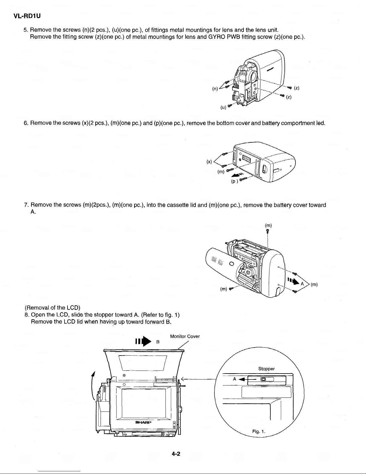
5. Remove the screws (n)(2
PCS.),
(u)(one
PC.), of
fittings metal mountings for
lens and the
lens unit.
Remove the fitting screw
(z)(one
PC.) of metal mountings for
lens
and GYRO PWB
fitting
screw (z)(one
PC.).
( >
n
6. Remove
the screws
(x)(2
PCS.), (m)(one PC.) and (p)(one
PC.),
remove the
bottom
cover
and battery comportment led.
7. Remove
the screws (m)(2pcs.), (m)(one PC.),
into the cassette lid and (m)(one PC.),
remove the battery cover toward
A.
( )
m
t
( >
m
(Removal of the LCD)
8. Open the LCD, slide the stopper toward A. (Refer to fig. 1)
Remove the LCD lid when having up toward forward B.
Monitor Cover
B
I
/
Stopper
\
4-2
VL-RI31 UJ
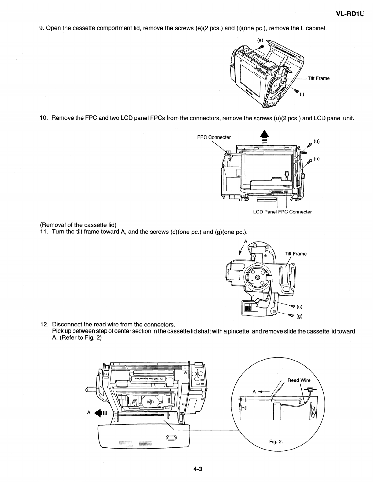
9. Open the cassette comportment lid, remove the screws (e)(2 PCS.) and (i)(one PC.), remove the L cabinet.
Tilt Frame
10. Remove the FPC and two LCD panel FPCs from the connectors, remove the screws (u)(2 PCS.) and LCD panel unit.
FPC Conn
\
ecter
LCD Panel FPC Connecter
(Removal of the cassette lid)
11. Turn the tilt frame toward A, and the screws (c)(one PC.) and (g)(one PC.).
ie
12. Disconnect the read wire from the connectors.
Pick up between step of center section in the cassette lid shaft with a pincette, and remove slide the cassette lid toward
A. (Refer to Fig. 2)
c
0
A
4-3
VL-RDl U
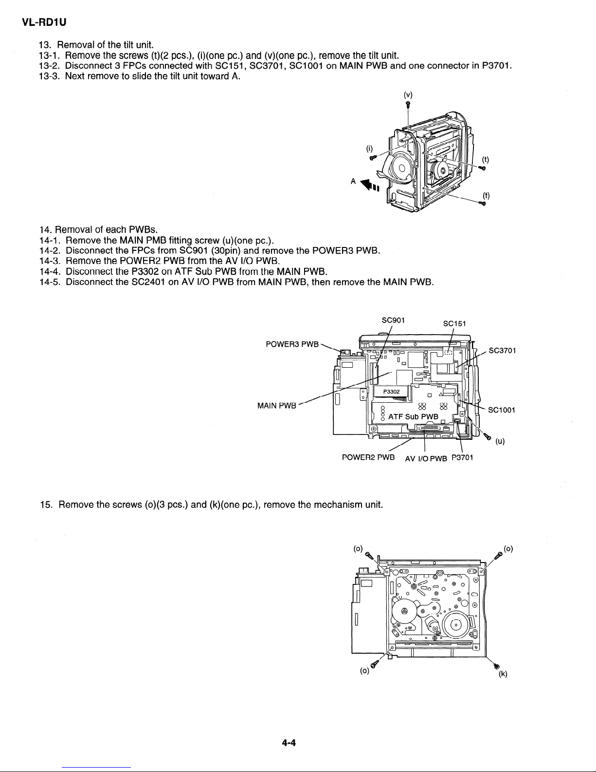
13. Removal of the tilt unit.
13-1. Remove the screws (t)(2 PCS.), (i)(one PC.) and (v)(one PC.), remove the tilt unit.
13-2. Disconnect 3 FPCs connected with SC151, SC3701, SC1 001 on MAIN PWB and one connector in P3701.
13-3. Next remove to slide the tilt unit toward A.
( 1
v
I?
(9
w
A
(9
T9
14. Removal of each PWBs.
14-1. Remove the MAIN PMB fitting screw (u)(one PC.).
14-2. Disconnect the FPCs from SC901 (30pin) and remove the POWER3 PWB.
14-3. Remove the POWER2 PWB from the AV I/O PWB.
14-4. Disconnect the P3302 on ATF Sub PWB from the MAIN PWB.
14-5. Disconnect the SC2401 on AV I/O PWB from MAIN PWB, then remove the MAIN PWB.
POWER3 PWB
MAIN PWB’
POWER2 PWB
AV i/O PWB P3701
15. Remove the screws (0)(3 PCS.) and (k)(one PC.), remove the mechanism unit.
4-4
VL-RDl U
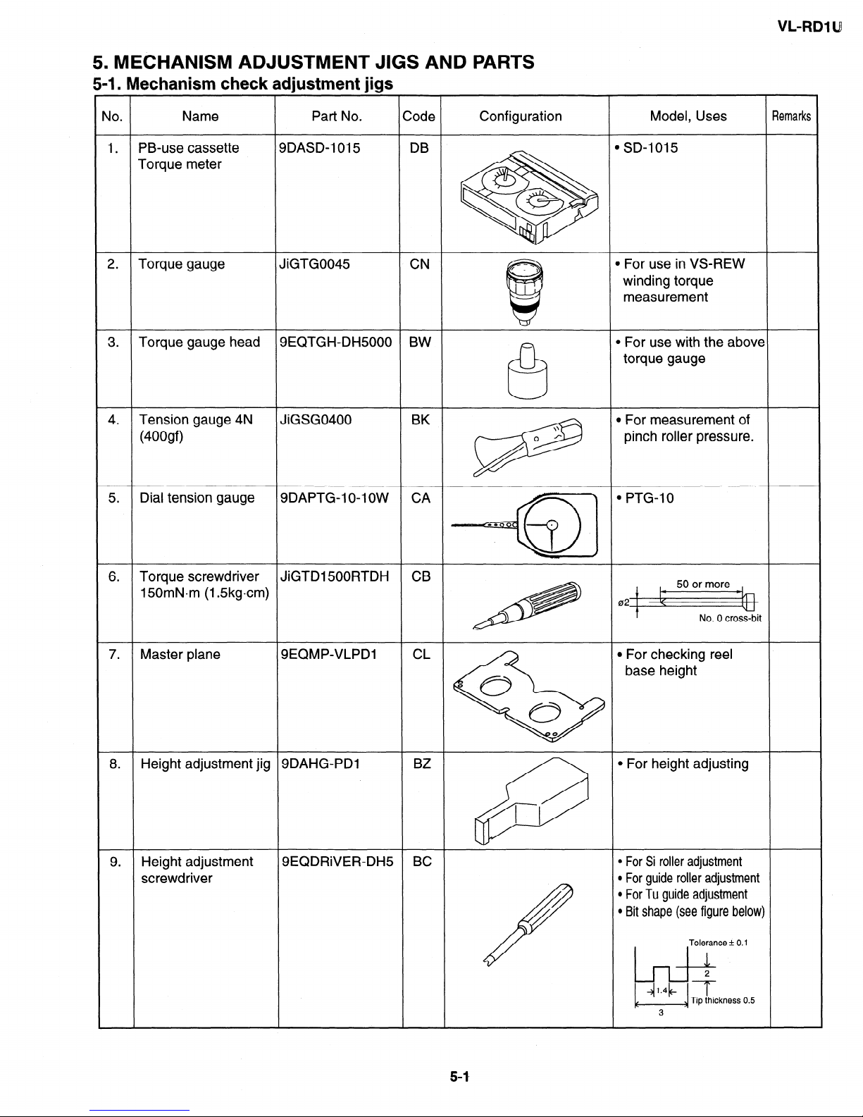
5. MECHANISM ADJUSTMENT JIGS AND PARTS
5-1. Mechanism check adjustment jigs
Name
Part No. ;ode
Configuration
Model, Uses
\lO.
lemarks
1. PB-use cassette
Torque meter
)DASD-1015 DB
1 SD-l 015
2. Torque gauge
JiGTG0045 CN
1 For use in VS-REW
winding torque
measurement
3. Torque gauge head
3EQTGH-DH5000 BW
b For use with the above
torque gauge
4.
Tension gauge 4N
(400gf)
JiGSG0400 BK
B For measurement of
pinch roller pressure.
\\
0 /*
P@
5. Dial tension gauge
CA
b PTG-10
3DAPTG-1 O-l OW
6. Torque screwdriver
150mNom (1.5kgcm)
JiGTD1500RTDH CB
I
50 or more
b-q-j
021 1
No. 0 cross-bit
7. Master plane
SEQMP-VLPDI CL
0
0
\
0
0
l For checking reel
base height
8. Height adjustment jig
SDAHG-PDI
BZ
l For height adjusting
66
1 I
9. Height adjustment
screwdriver
9EQDRiVER-DH5 BC
l For Si roller adjustment
l For guide roller adjustment
l For Tu guide adjustment
l Bit shape (see figure below
/
Tolerance & 0.1
Tip thickness 0.5
3
VL-RDl U
(3) Radio needle-nose pliers
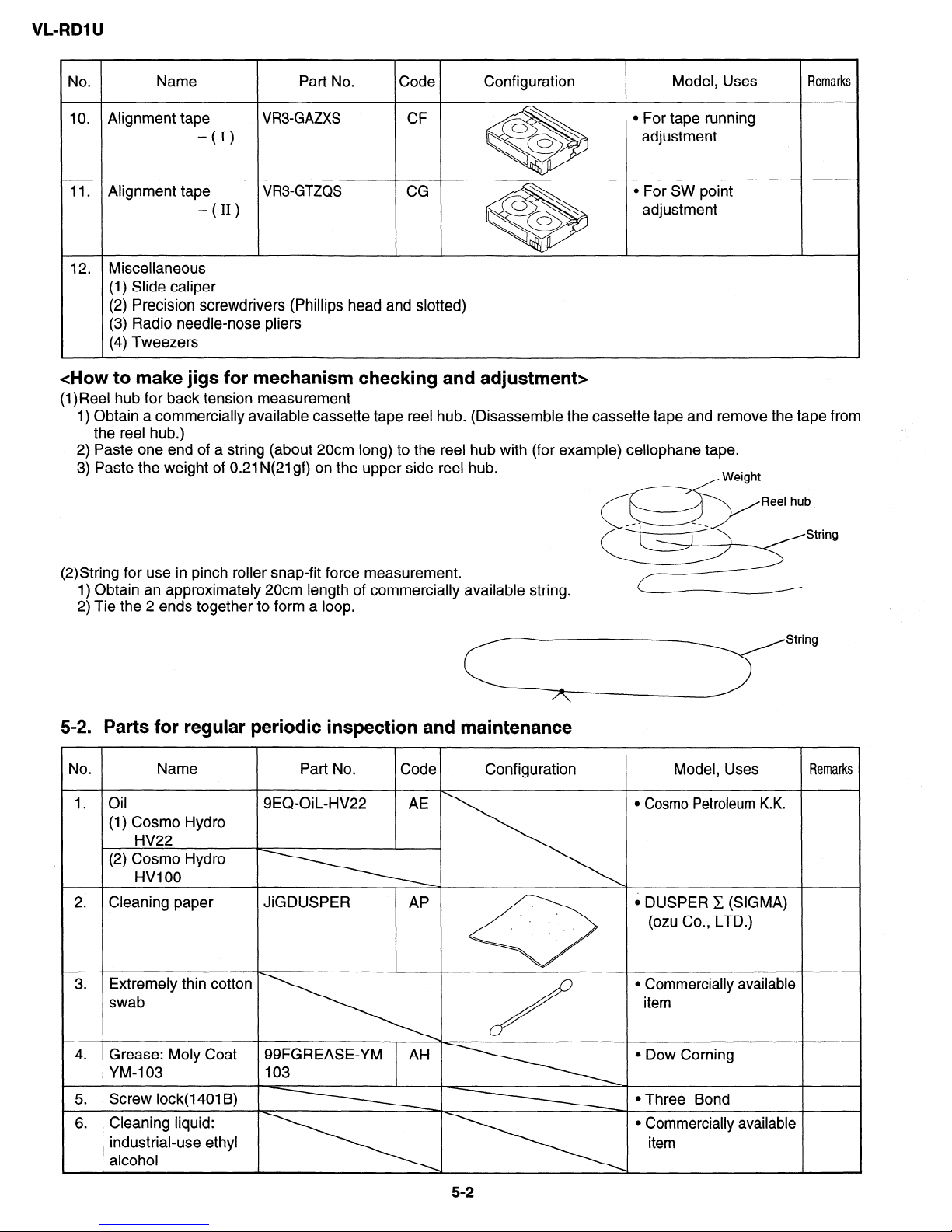
<How to make jigs for mechanism checking and adjustment>
(1)Reel hub for back tension measurement
1) Obtain a commercially available cassette tape reel hub. (Disassemble the cassette tape and remove the tape from
the reel hub.)
2) Paste one end of a string (about 20cm long) to the reel hub with (for example) cellophane tape.
3) Paste the weight of 0.21 N(21gf) on the upper side reel hub.
(2)String for use in pinch roller snap-fit force measurement.
1) Obtain an approximately 20cm length of commercially available string.
2) Tie the 2 ends together to form a loop.
5-2. Parts for regular periodic inspection and maintenance
Jo.
Name
1. . 011
(1) Cosmo Hydro
HV22
(2) Cosmo Hydro
HVI 00
2. Cleaning paper
Part No. Code
Configuration
Model, Uses
Remarks
9EQ-OiL-HV22 AE
l Cosmo Petroleum K.K.
JiGDUSPER
AP
6 DUSPER C (SIGMA)
. . .
. .
*
(ozu Co., LTD.)
. .
\
3.
Extremely thin cotton
swab
\ /
l Commercially available
item
4. Grease: Moly Coat 99FGREASE-YM AH
l Dow Corning
YM-103 103
5.
Screw lock(l401 B)
l Three Bond
6. Cleaning liquid:
l Commercially available
industrial-use ethyl
alcohol
VL-RDl lJ
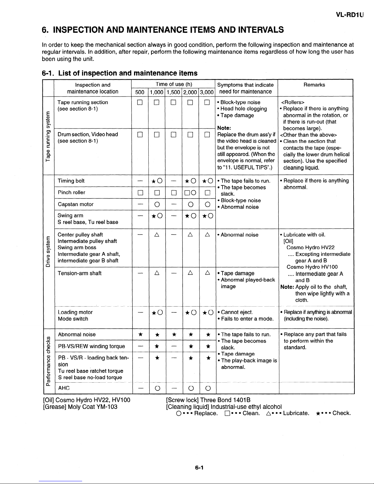
6. INSPECTION AND MAINTENANCE ITEMS AND INTERVALS
In order to keep the mechanical section always in good condition, perform the following inspection and maintenance at
regular intervals. In addition, after repair, perform the following maintenance items regardless of how long the user has
been using the unit.
6-l. List of inspection and maintenance items
Inspection and
Time of use (h)
Symptoms that indicate
Remarks
maintenance location
500 1,000 1,500 2,000 3,000 need for maintenance
Tape running section
cl q q
q
cl
l Block-type noise <Rollers>
E
(see section 8-1)
l Head hole clogging
l Replace if there is anything
a,
l Tape damage
abnormal in the rotation, or
z
z?
if there is run-out (that
Note:
F
becomes large).
.-
Drum section, Video head
0 17 [7 0
E
0 Repiace the drum ass’y if <Other than the above>
the video head is cleaned l Clean the section that
3
(see section 8-l)
:
but the envelope is not
contacts the tape (espe-
%
still appeared. (When the
cially the lower drum helical
I-
envelope is normal, refer
section). Use the specified
to “11. USEFUL TIPS”.)
cleaning liquid.
Timing belt
- *o -
* 0 * 0 l The tape fails to run.
l Replace if there is anything
abnormal.
Pinch roller
III 0 q 00 @
- l The tape becomes
slack.
Capstan motor
0
0 0
l Block-type noise
l Abnormal noise
Swing arm
- *o
- *o *o
S reel base, Tu reel base
E
Center pulley shaft
a,
Intermediate pulley shaft
5
g Swing arm boss
g
Intermediate gear A shaft,
‘iT:
intermediate gear B shaft
n
Tension-arm shaft
A - A a @Abnormal noise l Lubricate with oil.
[O II
i
Cosmo Hydro HV22
. . . . Excepting intermediate
gear A and B
Cosmo Hydro HVIOO
n - a a l Tape damage
. . . . Intermediate gear A
l Abnormal played-back
and B
image
Note: Apply oil to the shaft,
then wipe lightly with a
cloth.
Loading motor
- *o -
* 0 * 0 l Cannot eject.
l Replace if anything is abnormal
Mode switch l Fails to enter a mode.
(including the noise).
Abnormal noise
:
Ir * * * jt .The tape fails to run.
l Replace any part that fails
l The tape becomes
to perform within the
:
PBYS/REW winding torque - Ir - * *
slack.
standard.
a>
PB + VS/R . loading back ten- - * - * *
l Tape damage
:
sion
l The play-back image is
g
abnormal.
5
Tu reel base ratchet torque
‘t 2 S reel base no-load torque
AHC
0
0
0
[Oil] Cosmo Hydro HV22, HVIOO [Screw lock] Three Bond 1401 B
[Grease] Moly Coat YM-103 [Cleaning liquid] Industrial-use ethyl alcohol
0 l l l Replace.
q l l l Clean. A. l l Lubricate.
+P l l Check.
6-1
VL-RDl U
6-2. Precautions
(l)When replacing any part, always replace the cut washer that was removed with a new one.
(2)This mechanism does not have control adjustment. If the control cannot be set as required, clean and/or replace parts.
(3)On the oil
a) Always use the specified oil. (Using another kind of oil can cause various kinds of trouble.)
b) Always use clean oil, without any mixed-in dirt, to lubricate bearings. (Using oil with dirt mixed in can cause the
bearings to wear or to stick.)
c) One drop of oil is the amount shown in the figure below, on the point of a pin.
.:.:
..:.:.
::::
. .
.::::::. .g.
.:.:.:;
N
::;:3;:>:
j j::::
,.;:z::.:
::::: j::::. ,.,...,...
.~.~.~.~.~.: .::::~.:.:.~
. . . ..L...
1.5mm diameter
?:Z:C, .Z:F
..:.:::::y..
or less
Oil
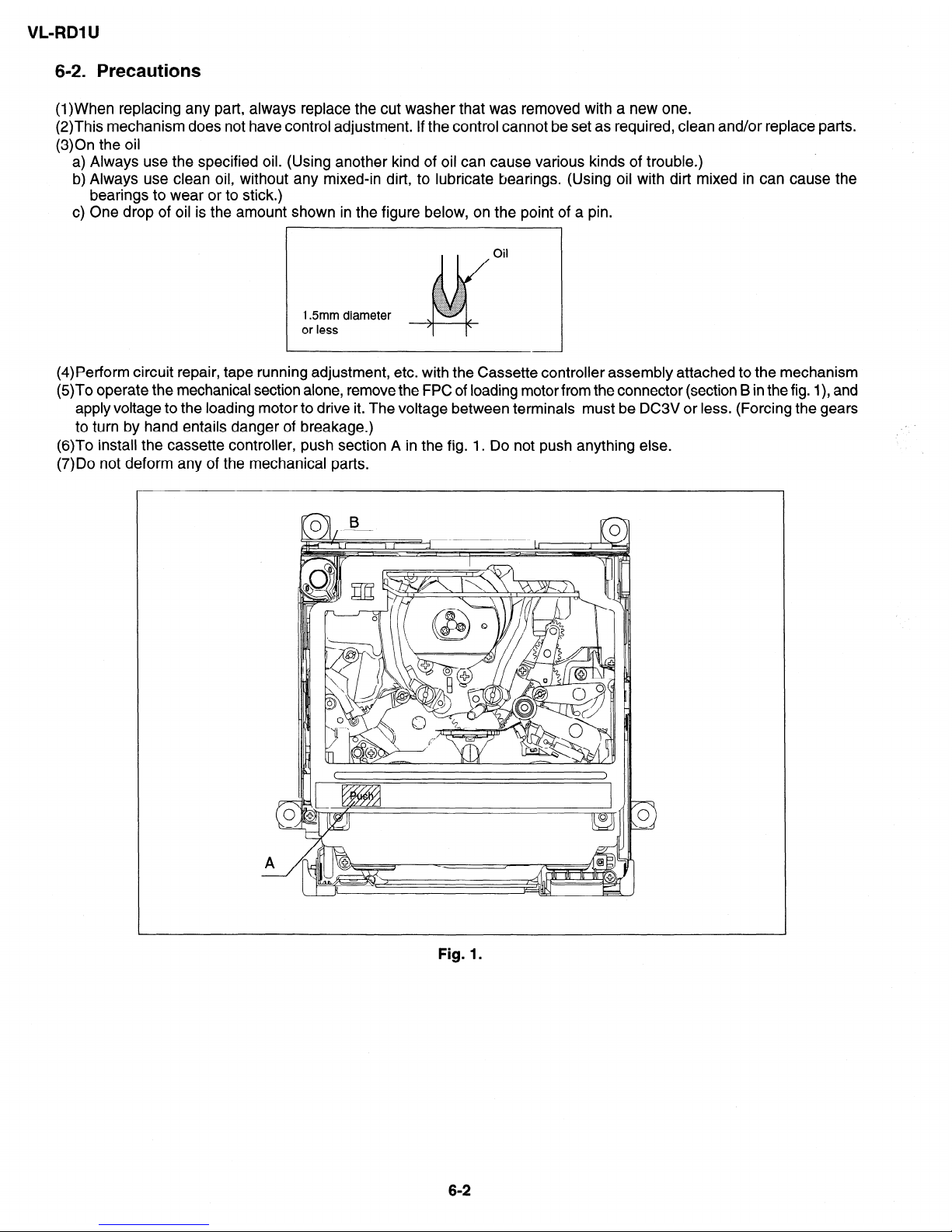
(4)Perform circuit repair, tape running adjustment, etc. with the Cassette controller assembly attached to the mechanism
(5)To operate the mechanical section alone, remove the FPC of loading motor from the connector (section B in the fig. I), and
apply voltage to the loading motor to drive it. The voltage between terminals must be DC3V or less. (Forcing the gears
to turn by hand entails danger of breakage.)
(6)To install the cassette controller, push section A in the fig. 1. Do not push anything else.
(7)Do not deform any of the mechanical parts.
Fig. 1.
6-2
VL-RDl U
7. MECHANICAL ADJUSTMENTS AND CHECKS
The items discussed here relate to general on-site servicing (field servicing). Adjustments and replacements that require
sophisticated facilities, jigs and technology are omitted.
1 n addition, in order to maintain the characteristics that the unit has when it is new, not only are inspection and maintenance
necessary, but it is absolutely necessary that, for example, the tape not be damaged, and always use jigs for adjustments
that require them.
<Precautions>
(1) Always set the power supply and state of the unit as follows for mechanism adjustments and checks.
1 AC adapter used, with cassette controller assembly 1
07-l Checking the playback (recording) winding torque
07-4 Back tension torque check and adjustment in record (playback) mode
1 AC adapter used, without cassette controller assembly (Independent Mechanism) 1
07-2 Checking the rewinding playback (VS-REW) winding torque
1 DC3V, without cassette controller assembly (Independent Mechanism) 1
07-3 Checking of reel base height
l 7-5 Checking and adjustment of tension roller position in record (playback) mode
07-6 Checking of supply S reel base no-load torque
07-7 Checking of loading back tension
07-8 Checking of winding Tu reel base ratchet torque
07-9 Checking of rewinding playback (VS-REW) back tension
07-10 Checking of pinch pressing force
(2) When performing checks with a DC3V power supply and independent mechanism, disconnect the loading motor
FPC from the connector.
(3) Always run the tape with the cassette controller assembly attached.
7-I. Checking the playback (recording) winding torque
(1)Set the torque cassette with the cassette controller assembly attached, then, in SP recording mode (playback mode
if a signal has already been recorded in SP mode on the tape), confirm that the torque on the winding side is within the
standard.
Winding torque standard in record (playback) mode
0.70 + 0.35mN.m (7.0 + 3.5gfocm),
ripple 0.2mN.m (2gfcm) or less
(If there is torque ripple, read the center value.)
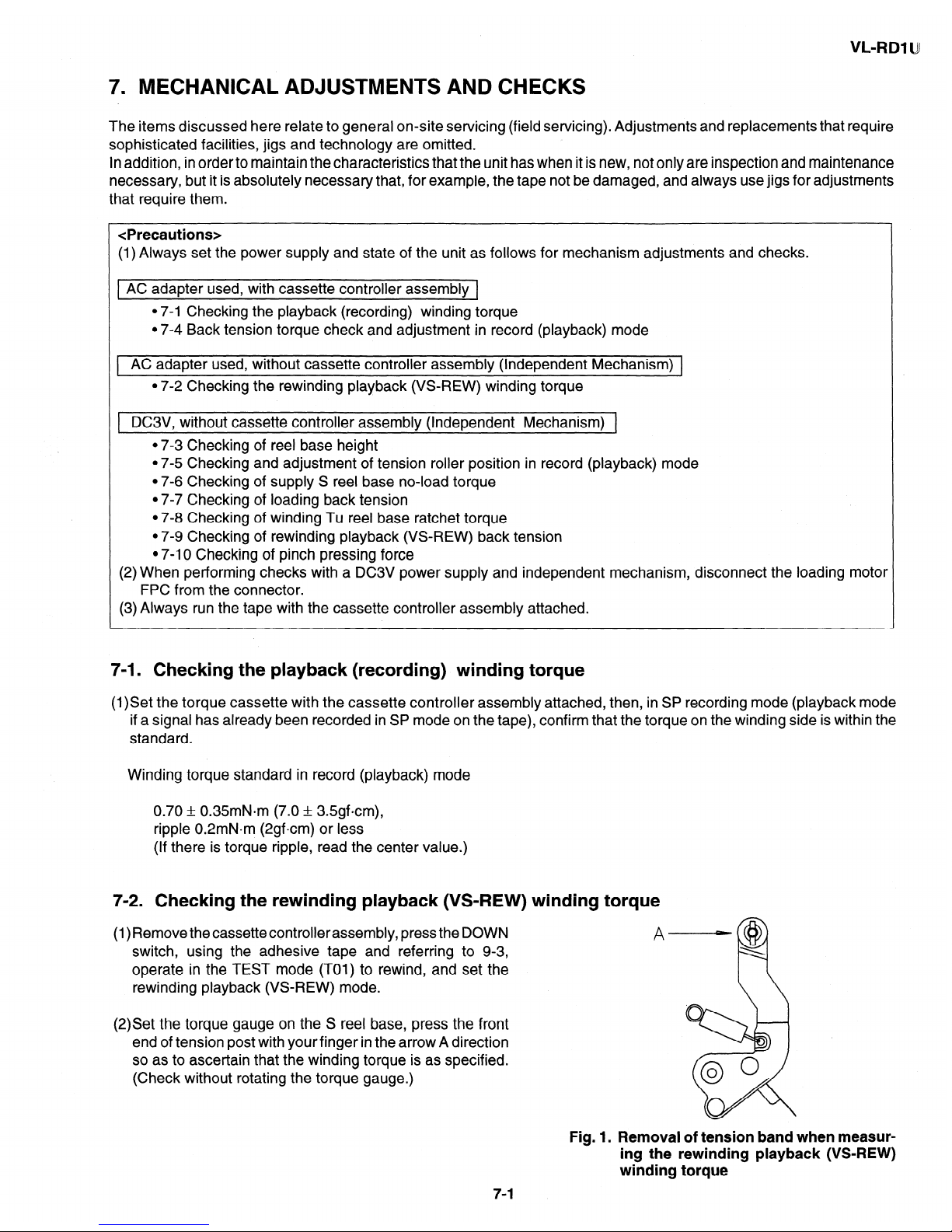
7-2. Checking the rewinding playback (VS-REW) winding torque
(l)Remove thecassettecontrollerassembly, pressthe DOWN
switch, using the adhesive tape and referring to 9-3,
operate in the TEST mode (TOI) to rewind, and set the
rewinding playback (VS-REW) mode.
(2)Set the torque gauge on the S reel base, press the front
end of tension post with your finger in the arrow A direction
so as to ascertain that the winding torque is as specified.
(Check without rotating the torque gauge.)
Fig. 1. Removal of tension band when measur-
ing the rewinding playback (VS-REW)
winding torque
7-1
VL-RDl U
Rewinding playback (VS-REW) winding torque standard
1.6 + O.GmN*m (16 + Ggfcm),
ripple 0.4mN.m (4gfcm) or less
(If torque ripple exists, read its center value.)
(3) After checking the winding torque remove the torque gauge, and remove the adhesive tape used in item (1) above (refer
to 9-3). The STANDBY mode is set automatically.
7-3. Checking of reel base height
(l)Remove the cassette controller assembly (refer to 9-2).
(2)Referring to 9-1, apply DC3V to the loading motor and put the system into playback mode.
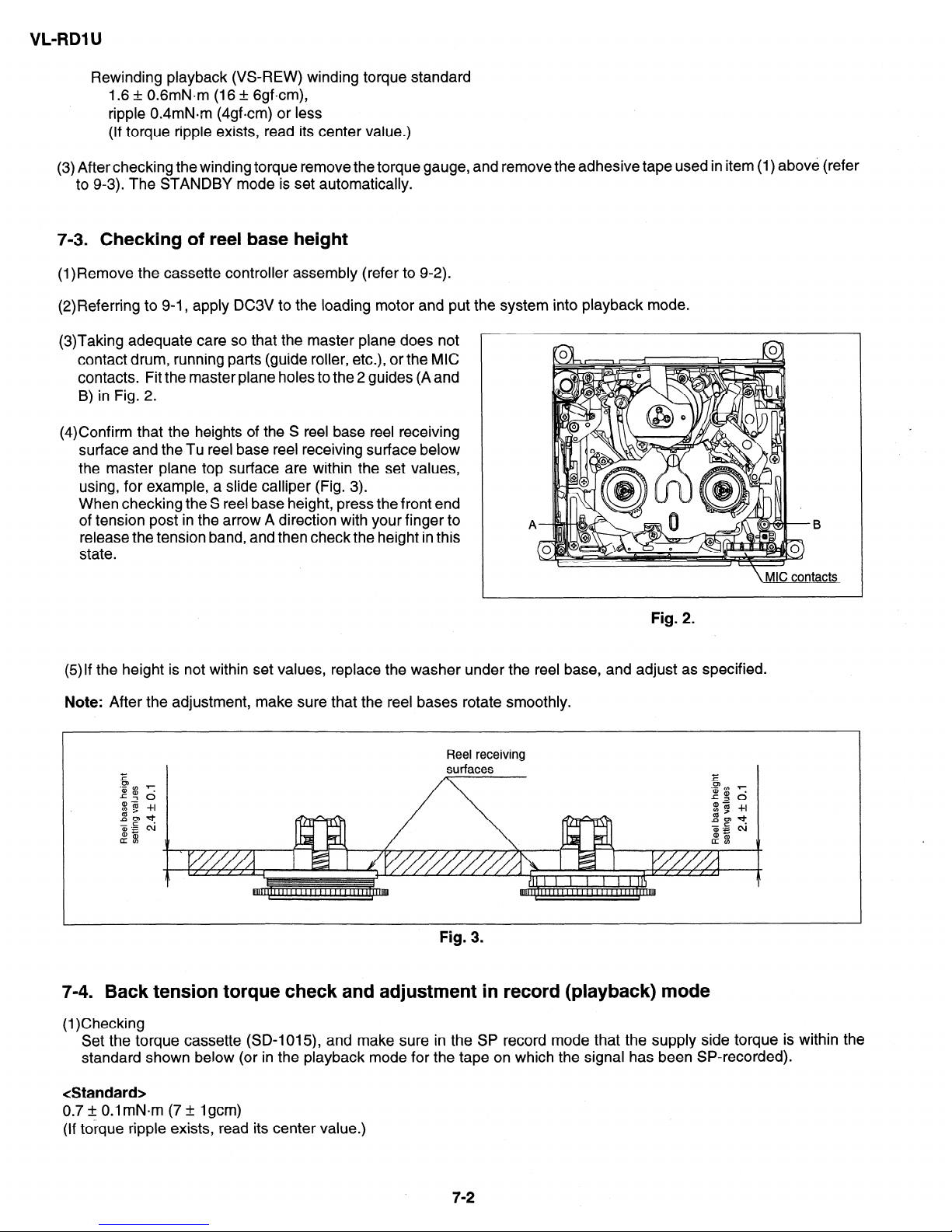
(3)Taking adequate care so that the master plane does not
contact drum, running parts (guide roller, etc.), or the MIC
contacts. Fit the master plane holes to the 2 guides (A and
B) in Fig. 2.
(4)Confirm that the heights of the S reel base reel receiving
surface and the Tu reel base reel receiving surface below
the master plane top surface are within the set values,
using, for example, a slide calliper (Fig. 3).
When checking the S reel base height, press the front end
of tension post in the arrow A direction with your finger to
release the tension band, and then check the height in this
state.
Fig. 2.
(5)If the height is not within set values, replace the washer under the reel base, and adjust as specified.
Note: After the adjustment, make sure that the reel bases rotate smoothly.
Reel receiving
surfaces
Fig. 3.
7-4. Back tension torque check and adjustment in record (playback) mode
(1)Checking
Set the torque cassette (SD-l015), and make sure in the SP record mode that the supply side torque is within the
standard shown below (or in the playback mode for the tape on which the signal has been SP-recorded).
<Standard>
0.7 + 0.1 mN*m (7 + 1 gem)
(If torque ripple exists, read its center value.)
7-2
VL-RDl L4
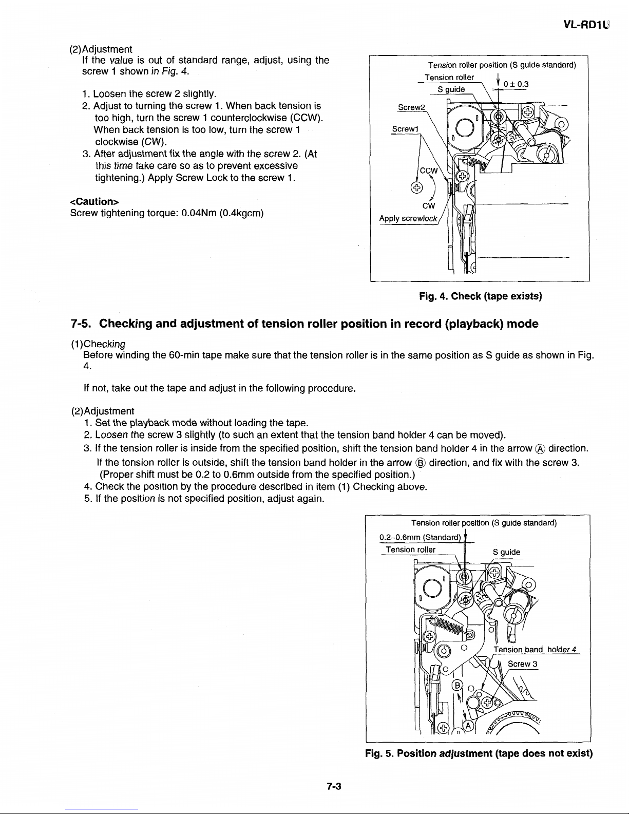
(2)Adjustment
If the value is out
of standard range, adjust, using the
screw
1 shown in Fig. 4.
Loosen the screw 2 slightly.
Adjust to turning the screw 1. When back tension is
too high, turn the screw 1 counterclockwise (CCW).
When back tension
is
too
low, turn the screw I
clockwise (CW).
After
adjustment fix the
angle with the screw 2. (At
this time take care so as to prevent excessive
tightening.) Apply Screw Lock to the
screw I.
<Caution>
Screw tightening
torque: 0.04Nm (0.4kgcm)
Tension roller position (S guide standard)
Tension
roller
~T\JF
cw
Apply screwlock
Fig. 4. Check (tape exists)
7-5. Checking and adjustment of tension roller position in record (playback) mode
(1)Checking
Before winding the 60-min tape make sure that the tension roller is in the same position as S guide as shown in Fig.
4.
If not, take out the tape and adjust in the following procedure.
(2)Adjustment
1. Set the playback mode without loading the tape.
2. Loosen the screw 3 slightly (to such an extent that the tension band holder 4 can be moved).
3. If the tension roller is inside from the specified position, shift the tension band holder 4 in the arrow @ direction.
If the tension roller is outside, shift the tension band holder in the arrow @J direction, and fix with the screw 3.
(Proper shift must be 0.2 to 0.6mm outside from the specified position.)
4. Check the position by the procedure described in item (1) Checking above.
5. If the position is not specified position, adjust again.
Tension roller position (S guide standard)
Fig. 5. Position adjustment (tape does not exist)
7-3
VL-RDl U
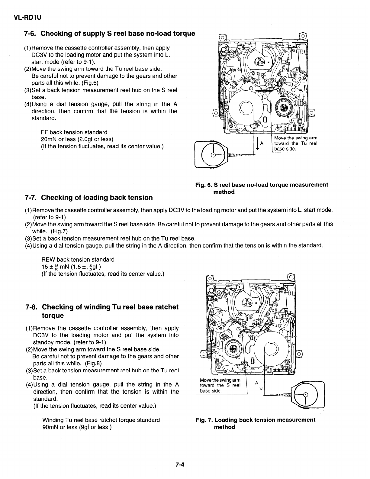
7-6. Checking of supply S reel base no-load torque
(l)Remove the cassette controller assembly, then apply
DC3V to the loading motor and put the system into L.
start mode (refer to 9-l).
(2)Move the swing arm toward the Tu reel base side.
Be careful not to prevent damage to the gears and other
parts all this while. (Fig.6)
(3)Set a back tension measurement reel hub on the S reel
base.
(4)Using a dial tension gauge, pull the string in the A
direction, then confirm that the tension is within the
standard.
FF back tension standard
20mN or less (2.0gf or less)
(If the tension fluctuates, read its center value.)
Fig. 6. S reel base no-load torque measurement
method
7-7. Checking of loading back tension
(l)Remove the cassette controller assembly, then apply DC3V to the loading motor and put the system into L. start mode.
(refer to 9-l)
(2)Move the swing arm toward the S reel base side. Be careful not to prevent damage to the gears and other parts all this
while. (Fig.7)
(3)Set a back tension measurement reel hub on the Tu reel base.
(4)Using a dial tension gauge, pull the string in the A direction, then confirm that the tension is within the standard.
REW back tension standard
15&igrnN (1.5+gf)
(If the tension fluctuates, read its center value.)
7-8. Checking of winding Tu reel base ratchet
torque
(l)Remove the cassette controller assembly, then apply
DC3V to the loading motor and put the system into
standby mode. (refer to 9-l)
(2)Move the swing arm toward the S reel base side.
Be careful not to prevent damage to the gears and other
parts all this while. (Fig.8)
(3)Set a back tension measurement reel hub on the Tu reel
base.
(4)Using a dial tension gauge, pull the string in the A
direction, then confirm that the tension is within the
standard.
(If the tension fluctuates, read its center value.)
Winding Tu reel base ratchet torque standard
90mN or less (9gf or less )
Move the swing arm
toward the S reel
base side.
Fig. 7. Loading back tension measurement
method
7-4
VL-RDl U
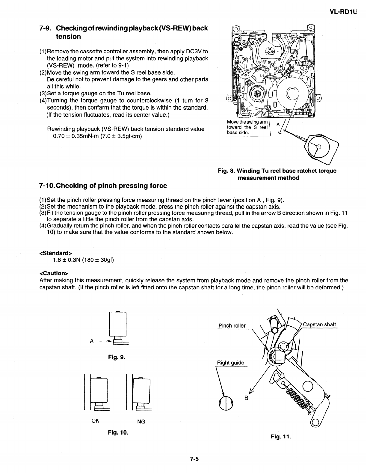
7-9. Checking of rewinding playback(VS-REW) back
tension
(l)Remove the cassette controller assembly, then apply DC3V to
the loading motor and put the system into rewinding playback
(VS-REW) mode. (refer to 9-1)
(2)Move the swing arm toward the S reel base side.
Be careful not to prevent damage to the gears and other parts
all this while.
(3)Set a torque gauge on the Tu reel base.
(4)Turning the torque gauge to counterclockwise (1 turn for 3
seconds), then confarm that the torque is within the standard.
(If the tension fluctuates, read its center value.)
Rewinding playback (VS-REW) back tension standard value
0.70 + 0.35mN.m (7.0 + 3.5gfcm)
base side.
Fig. 8. Winding Tu reel base ratchet torque
measurement method
7-l O.Checking of pinch pressing force
(l)Set the pinch roller pressing force measuring thread on the pinch lever (position A , Fig. 9).
(2)Set the mechanism to the playback mode, press the pinch roller against the capstan axis.
(3)Fit the tension gauge to the pinch roller pressing force measuring thread, pull in the arrow B direction shown in Fig. 11
to separate a little the pinch roller from the capstan axis.
(4)Gradually return the pinch roller, and when the pinch roller contacts parallel the capstan axis, read the value (see Fig.
10) to make sure that the value conforms to the standard shown below.
<Standard>
1.8 + 0.3N (180 + 30gf)
<Caution>
After making this measurement, quickly release the system from playback mode and remove the pinch roller from the
capstan shaft. (If the pinch roller is left fitted onto the capstan shaft for a long time, the pinch roller will be deformed.)
&
A-
Fig. 9.
Fig. 10.
Right guide
\
NG
Fig. 11.
7-5
VL-RDl
U
8. TAPE
RUNNING ADJUSTMENT
8-l. Adjustment locations
<Replacement parts>
. S guide
- T
roller,
arm
-
Tu guide, arm
-
Slide
chassis
replaced
parts with the
Adjustment
procedure
8-2
<Replacement parts other
than
those
shown
above>
-
Ball base
-
Guide
roller
_
Height
presetting
is
not
_
-
Drum
assembly
necessary.
-
Cap motor, etc.
Running rough
adjustment
Adjustment
procedure
8-4
Cassette controller
installation
Running final
adjustment
Adjustment
procedure
8-5
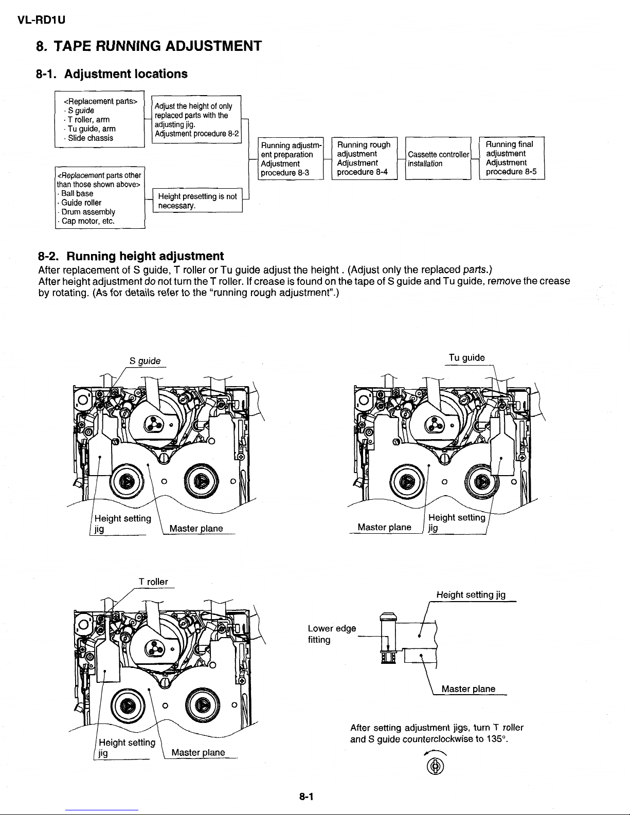
8-2. Running height
adjustment
After
replacement of S guide, T roller or Tu guide adjust the height
. (Adjust only the replaced parts.)
After height adjustment do
not turn the T roller. If crease is found
on the tape of S guide and Tu guide,
remove
the crease
by rotating.
(As
for details refer
to
the “running rough adjustment”.)
S guide
T roller
Tu guide
rr Master plane
1
Lower edge
fitting
Height setting jig
\ Master plane
After setting adjustment jigs, turn T roller
and S guide counterclockwise to 135”.
8-1
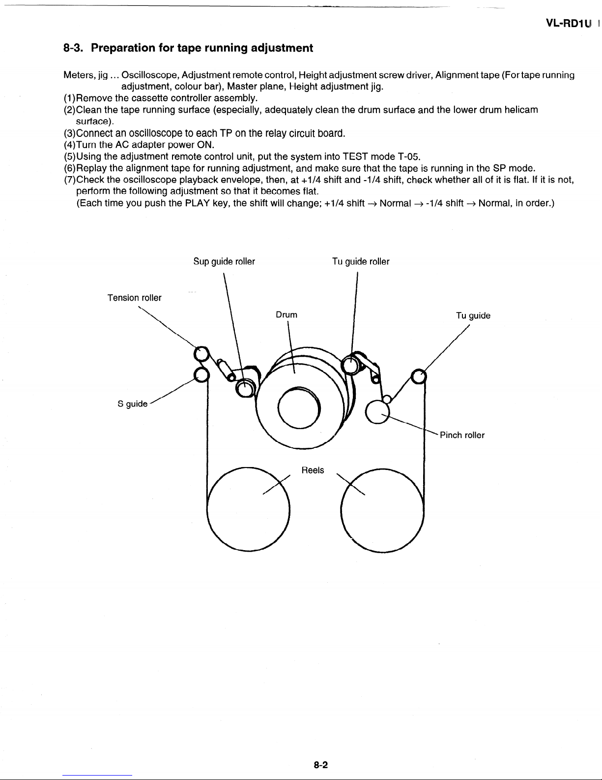
8-3. Preparation for tape running adjustment
Meters, jig
. . . Oscilloscope, Adjustment remote control, Height adjustment screw driver, Alignment tape (For tape running
adjustment, colour bar), Master plane, Height adjustment jig.
(l)Remove the cassette controller assembly.
(2)Clean the tape running surface (especially, adequately clean the drum surface and the lower drum helicam
surface).
(3)Connect an oscilloscope to each TP on the relay circuit board.
(4)Turn the AC adapter power ON.
(5)Using the adjustment remote control unit, put the system into TEST mode T-05.
(6)Replay the alignment tape for running adjustment, and make sure that the tape is running in the SP mode.
(7)Check the oscilloscope playback envelope, then, at +I/4 shift and -l/4 shift, check whether all of it is flat. If it is not,
perform the following adjustment so that it becomes flat.
(Each time you push the PLAY key, the shift will change; +I/4 shift -+ Normal -+ -l/4 shift -+ Normal, in order.)
Sup guide roller Tu guide roller
S guide
2
Tension roller
Tu guide
’ Pinch roller
8-2
VL-RDl U
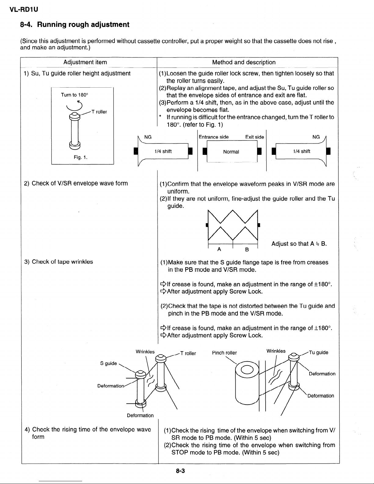
8-4. Running rough adjustment
(Since this adjustment is performed without cassette controller, put a proper weight so that the cassette does not rise ,
and make an adjustment.)
Adjustment item
I
Method and description
Su, Tu guide roller height adjustment
Turn to 180”
L-5
T roller
Fig. 1.
Check of V/SR envelope wave form
(l)Loosen the guide roller lock screw, then tighten loosely so that
the roller turns easily.
(2)Replay an alignment tape, and adjust the Su, Tu guide roller so
that the envelope sides of entrance and exit are flat.
(3)Perform a l/4 shift, then, as in the above case, adjust until the
envelope becomes flat.
* If running is difficult for the entrance changed, turn the T roller to
180”. (refer to Fig. 1)
Entrance side
Exit side
Normal
I
I
(l)Confirm that the envelope waveform peaks in V/SR mode are
uniform.
(2)If they are not uniform, fine-adjust the guide roller and the Tu
guide.
’ A
I
B ’
Adjust so that A % B.
Check of tape wrinkles
(l)Make sure that the S guide flange tape is free from creases
in the PB mode and V/SR mode.
Qlf crease is found, make an adjustment in the range of +180°.
QAfter adjustment apply Screw Lock.
(2)Check that the tape is not distorted between the Tu guide and
pinch in the PB mode and the V/SR mode.
Qlf crease is found, make an adjustment in the range of f180”.
QAfter adjustment apply Screw Lock.
Deformation
T roller
Pinch
Check the rising time of the envelope wave
form
(1)Check the rising time of the envelope when switching from V/
SR mode to PB mode. (Within 5 set)
(2)Check the rising time of the envelope when switching from
STOP mode to PB mode. (Within 5 set)
8-3
VL-RDl U
8-5. Final running adjustment
(Perform adjustment without removing the cassette controller.)
Adjustment item Method and description
1) Adjustment of Sup and Tu guide roller height
(1)lf the envelope waveform changes from the roughly adjusted
one, adjust again the height of guide roller.
(2)Finally adjust the lock screw of Sup and Tu guide roller.
(3)Once perform unloading and then loading to set the PB
mode, and make sure that the envelope waveform does not
change.
2) Adjustment of playback SWP
(1)Playback the colour bar tape.
(2) Perform SWP automatic adjustment with adjustment remote
control.
0-4
VL-RDI U
9. MECHANICAL SECTION ASSEMBLY AND PARTS REPLACEMENT
(DISASSEMBLY AND REASSEMBLY)
Mechanical section disassembly and reassembly are explained in this section.
For removal of the cabinet, etc., refer to 4. DISASSEMBLY OF THE SET.
<Precautions>
1. Always replace cut washers that have been removed, for example in parts replacement, with new ones.
2. When reassembling, be careful not to allow screws, washers or foreign matter to enter. They can cause mechanical
misoperation.
3. Use the cleaning liquid, oil, grease and screw lock that are specified below. Use of any other kind can cause
mechanical misoperation.
Oil:
Cosmo Petroleum : Cosmo Hydro HV22/HVlOO
Grease:
Dow Corning : Moly Coat YM-103
Screw lock: Three Bond :1401B
Cleaning liquid: Industrial-use ethyl alcohol
4. Turn the mechanical section over, do not place it on, for example, a desk. Deformation and scratching of mechanical
parts can cause trouble.
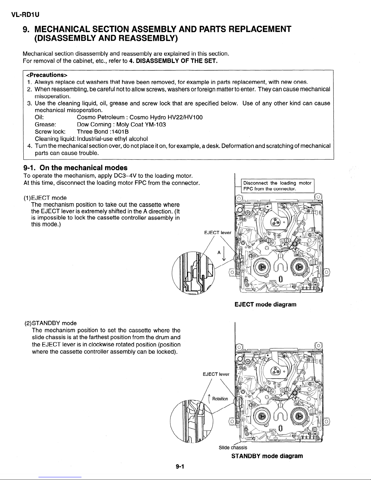
9-l. On the mechanical modes
To operate the mechanism, apply DC3-4V to the loadinq motor.
_
At this time, disconnect the loading motor FPC from the connector.
(1)EJECT mode
The mechanism position to take out the cassette where
the EJECT lever is extremely shifted in the A direction. (It
is impossible to lock the cassette controller assembly in
this mode.)
(2)STANDBY mode
The mechanism position to set the cassette where the
slide chassis is at the farthest position from the drum and
the EJECT lever is in clockwise rotated position (position
where the cassette controller assembly can be locked).
EJEC’
T lev
\
EJECT mode diagram
3
0
Slide chassis
STANDBY mode diagram
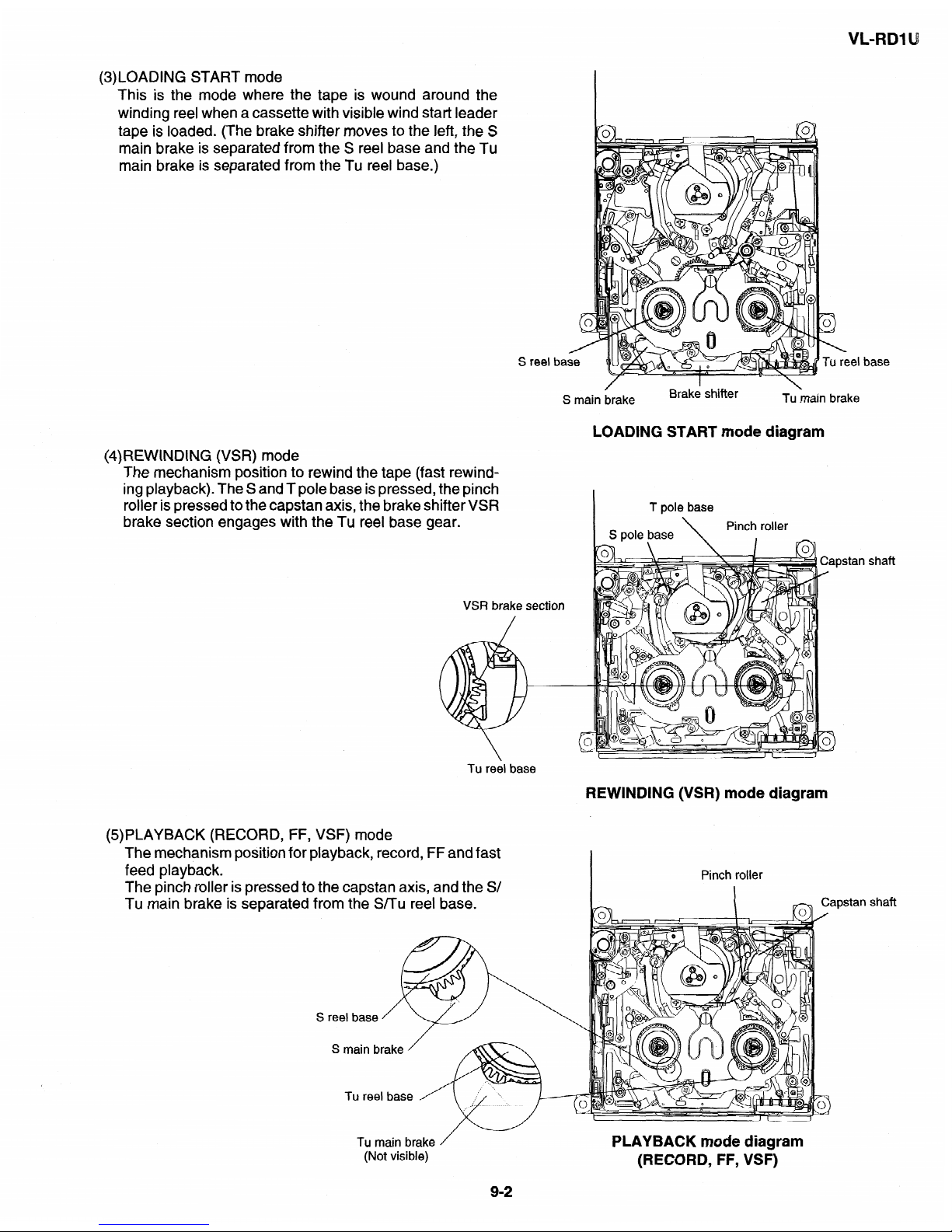
(3)LOADING START
mode
This is the mode where the
tape
is wound
around the
winding reel when a cassette with visible wind start
leader
tape is loaded.
(The
brake shifter
moves
to
the left, the S
main brake is separated from the S reel
base
and
the Tu
main brake is
separated from the Tu reel base.)
\
reel base
(4)REWINDING (VSR) mode
The mechanism position to rewind the tape (fast rewind-
ing playback). The S and T
pole base is pressed, the pinch
roller is pressed to the capstan axis, the brake shifter VSR
brake section engages with the Tu reel base gear.
VSR brake section
Tu reel base
S
main &rake
Brake shifter
Tu ‘main
brake
LOADING START mode diagram
(5)
T pole base
S pole base
\
Pinch roller
I
-
Istan shaft
REWINDING (VSR)
mode
diagram
iPLAYBACK (RECORD, FF, VSF) mode
The mechanism position for playback, record, FF and fast
feed playback.
The pinch roller is pressed to the capstan axis, and the S/
Tu main brake is separated from the Smu reel base.
S main brake /
Tu main brake
/
PLAYBACK mode diagram
(Not visible)
(RECORD, FF, VSF)
9-2
VL-RDl U
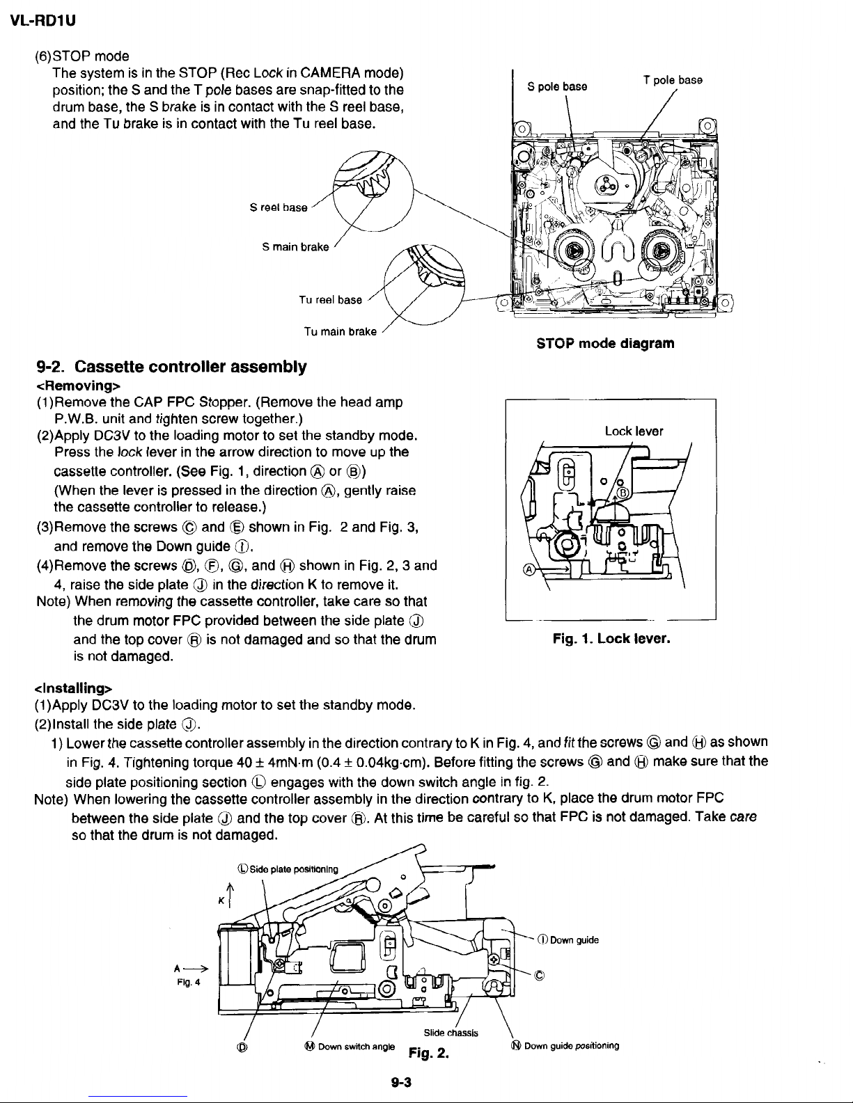
(6)STOP
mode
The system is in the
STOP (Ret Lock in CAMERA mode)
position; the S and the T pole
bases
are
snap-fitted to the
drum base,
the S brake
is in
contact with the S reel base,
and
the
Tu brake
is in
contact with the Tu reel base.
S
main brake
Tu main brake
/-
9-2. Cassette controller assembly
<Removing>
(l)Remove the CAP FPC Stopper. (Remove the head amp
P.W.B. unit and tighten screw together.)
(2)Apply DC3V to the loading motor
to set the standby mode.
Press the lock lever in the arrow direction to move up the
cassette controller. (See Fig. 1, direction @ or @jI)
(When the lever is pressed in
the direction 8, gently raise
the cassette controller to release.)
(3)Remove the screws @ and @ shown in Fig. 2 and Fig. 3,
and remove the Down guide 0.
(4)Remove the screws @,, 0, 0, and @ shown in Fig. 2,3 and
4, raise the side plate
@ in the direction K to remove it.
Note) When removing the cassette controller, take care so that
the drum motor FPC provided between the side plate @
and the top cover @I is not damaged and so that the drum
is not damaged.
STOP
mode
diagram
Lock lever
Fig. 1. Lock lever.
<Installing>
(1)Apply DC3V to the loading motor to set the standby mode.
(2)lnstall the side plate 0.
1) Lower the cassette controller assembly in the direction contrary to K in Fig. 4, and fit the screws @ and @ as shown
in Fig. 4. Tightening torque 40 f 4mN.m (0.4 f 0.04kgcm). Before fitting the screws @ and @ make sure that the
side plate positioning section 0 engages with the down switch angle in fig. 2.
Note) When lowering the cassette controller assembly in the direction contrary to K, place the drum motor FPC
between the side plate @ and the top cover @. At this time be careful so that FPC is not damaged. Take care
so that the drum is not damaged.
OSiie plate positionin
@ Down guide
A+
Fig. 4
0
Down switch angle
Down guide positioning
VL-RDl U
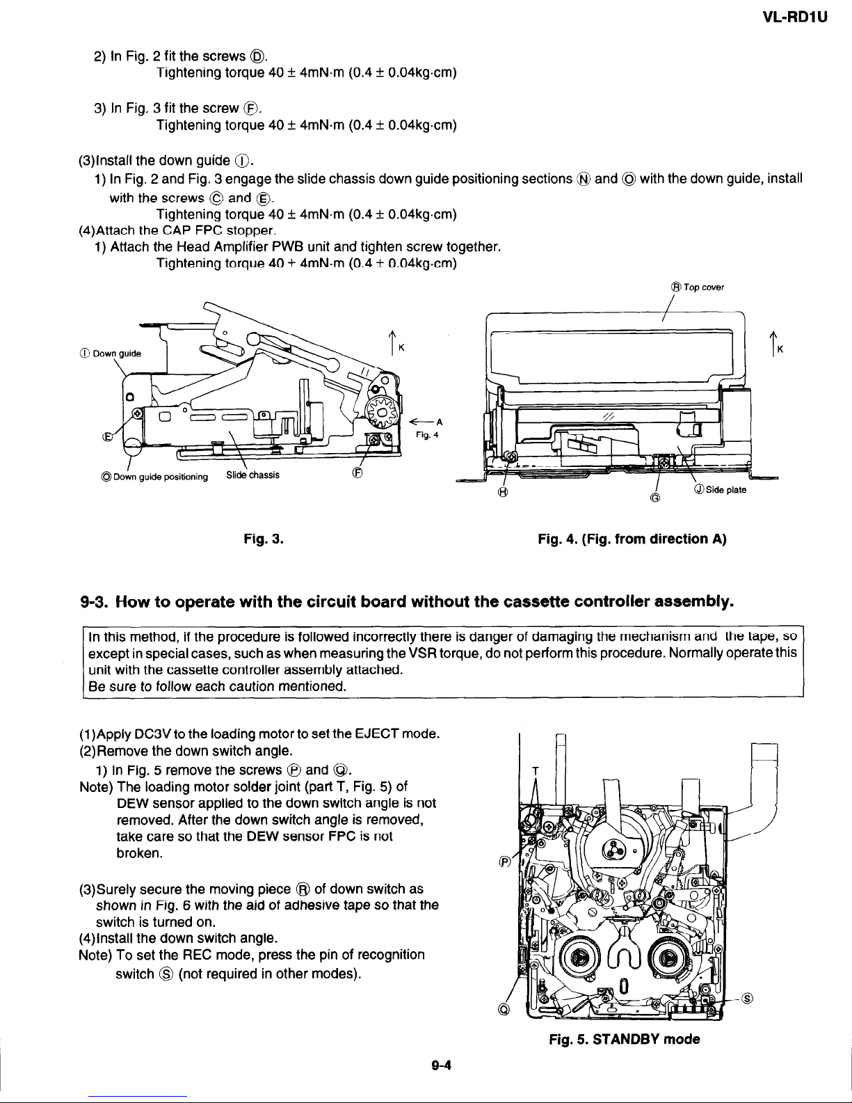
2) In Fig. 2 fit the screws @$.
Tightening torque 40 + 4mN.m (0.4 + 0.04kgcm)
3) In Fig. 3 fit the screw 0.
Tightening torque 40 + 4mN-m (0.4 f 0.04kgcm)
(3)lnstall the down guide 0.
1) In Fig. 2 and Fig. 3 engage the slide chassis down guide positioning sections @ and @ with the down guide, install
with the screws 0 and 0.
Tightening torque 40 + 4mN.m (0.4 f 0.04kg.cm)
(4)Attach the CAP FPC stopper.
1) Attach the Head Amplifier PWB unit and tighten screw together.
Tightening torque 40 f 4mN.m (0.4 f 0.04kgcm)
I
@Down guide positioning
Slide\ chassis
Fig. 3.
+--A
Fig. 4
@J Top cover
r,
Fig. 4. (Fig. from direction A)
9-3. How to operate with the circuit board without the cassette controller assembly.
In this method, if the procedure is followed incorrectly there is danger of damaging the mechanism and the tape, so
except in special cases, such as when measuring the VSR torque, do not perform this procedure. Normally operate this
unit with the cassette controller assembly attached.
Be sure to follow each caution mentioned.
(1)Apply DC3V to the loading motor to set the EJECT mode.
(2)Remove the down switch angle.
1) In Fig. 5 remove the screws @ and @$.
Note) The loading motor solder joint (part T, Fig. 5) of
DEW sensor applied to the down switch angle is not
removed. After the down switch angle is removed,
take care so that the DEW sensor FPC is not
broken.
(3)Surely secure the moving piece @ of down switch as
shown in Fig. 6 with the aid of adhesive tape so that the
switch is turned on.
(4)lnstall the down switch angle.
Note) To set the REC mode, press the pin of recognition
switch @ (not required in other modes).
I l-4
n
Fig. 5. STANDBY mode
9-4
VL-RDl U
(5)Set the
test
mode
(T-01)
with the
adjustment remote controller without
loading the tape. Thereby
the mechanism
operation
is enabled with the
mode key.
(6)To
eject,
remove the tape (3).
Down
switch
angle
Adhesive
tape
Fig. 6.
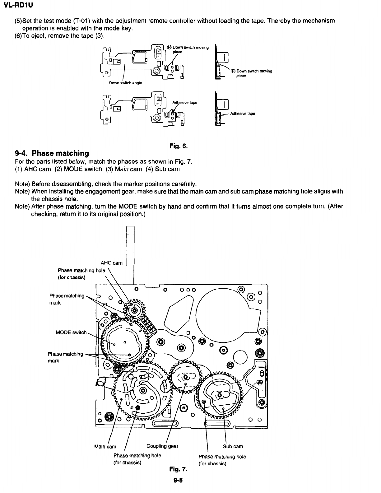
9-4.
Phase
matching
For
the parts listed
below,
match
the phases
as shown in
Fig. 7.
(1) AHC cam
(2) MODE
switch (3) Main
cam
(4) Sub
cam
Note) Before disassembling, check the marker positions carefully.
Note) When installing the engagement gear, make
sure that the main cam
and sub cam phase matching hole aligns with
the chassis hole.
Note)
After phase matching, turn the MODE
switch by hand and confirm that it turns almost one complete turn. (After
checking, return it to
its
original position.)
AHC cam
I
Phase
matching hole
(for
chassis)
\I \
Phase matching
mark
?-
0
000 B_ol
MODE switch
Phase matching
mark
Main dam /
Coupling gear
I
Sub cam
Phase matching hole
Phase matching hole
(for chassis)
(for chassis)
Fig. 7.
 Loading...