

Page 1

SHARP SERVICE MANUAL
LIQUID CRYSTAL CAMCORDER q NTSC
VL-E760
MODELS VL-E765
In the interests of user-safety (Required by safety regulations in some countries) the set should be restored to its
original condition and only parts identical to those specified
be used.
VL-E760U
VL-E765U
I
1.
IMPORTANT SERVICE NOTES
2 .
SPECIFICATIONS
3
PART NAMES AND FUNCTION . . . . . . . . . . . . . . . . . . . . . . . . . . . . . . . . . . . . . . . . . . . . . . . . . . . . . . . . . . . . . . . . . . . . . . . . . . . . . . . . . . . . . . . . . . . . . . . . . . . . . . 3-1
4:
DISASSEMBLY OF THE SET
.
5
MECHANISM ADJUSTMENT . . . . . . . . . . . ..I..............................................................~.............................
.
6
ADJUSTMENT OF VCR
7 .
SYSTEM BLOCK DIAGRAM . . . . . . . . . . . . . . . . . . . . . . . . . . . . . . . . . . . . . . . . . . . . . . . . . . . . . . . . . . . . . . . . . . . . . . . . . . . . . . . . . . . . . . . . . . . . . . . . . . . . . . . . . . .
8 .
SCHEMATIC DIAGRAMS . . . . . . . . . . . . . . . . . . . . . . . . . . . . . . . . . . . . . . . . . . . . . . . . . . . . . . . . . . . . . . . . . . . . . . . . . . . . . . . . . . . . . . . . . . . . . . . . . . . . . . . . . . . . . . .
9 .
SEMICONDUCTOR LEAD IDENTIFICATION
lO.PRINTED WIRING BOARD ASSEMBLIES
11 .REPLACEMENT PARTS LIST . . . . . . . . . . . . . . . . . . . . . . . . . . . . . . . . . . . . . . . . . . . . . . . . . . . . . . . . . . . . . . . . . . . . . . . . . . . . . . . . . . . . . . . . . . . . . . ..~.....
12.PACKING OF THE SET
13.AC ADAPTER . . . . . . . . . . . . . . . . . . . . . . . . . . . . . . . . . . . . . . . . . . . . . . . . . . . . . . . . . . . . . . . . . . . . . . . . . . . . . . . . . . . . . . . . . . . . . . . . . . . . . . . . . . . . . . . . . . . . . . . . .......
SHARP CORPORATlON
. . . . . . . . . . . . . . . . . . . . . . . . . . . . . . . . . . . . . . . . . . . . . . . . . . . . . . . . . . . . . . . . . . . . . . . . . . . ..~.......................~.....................
. . . . . . . . . . . . . . . . . . . . . . . . . . . . . . . . . . . . . . . . . . . . . . . . . . . . . . . . . . . . . . . . . . . . . . . . . . . . . . . . . . . . . . . . . . . . . . . . . . . . . . . . . . . . . . . . . . . 6-1
. . . . . . . . . . . . . . . . . . . . . . . . . . . . . . . . . . . . . . . . . . . . . . . . . . . . . . . . . . . . . . . . . . . . . . . . . . . . . . . . . . . . . . . . . . . . . . . . . . . . . . . . . . . . . . . .
. . . . . . . . . . . . . . . . . . . . . . . . . . . . . . . . . . . . . . . . . . . . . . . . . . . . . . . . . . . . ..~......................................
. . . . . . . . ..~...............................................................................~...............
CONTENTS
. . . . . . . . . . . . . . . . . . . . . . ..‘....................................................... 9-l
. . . . . . . . . . . . . . . . . . . . . . . . . . . . . . . . . . . . . . . . . . . . . . . . . . . . . . . . . . . . . . . . . . . . . . . . . . . . . . . . . . .
This document has been published to be used for
after sales service only.
The contents are subject to change without notice.
Page
l-l
2-1
4-l
5-I
7-1
8-1
IO-I
II-I
12-1
13-1
Page 2

VL-E760U
VL-E765U
1. IMPORTANT SERVICE NOTES
BEFORE RETURNING THE VIDEO CAMERA
RECORDER
Before returning the video camera recorder to the user,
perform the following safety checks.
1. Inspect all lead dress to make certain that leads are
not pinched or that hardware is not lodged between
the chassis and other metal parts in the video camera
recorder.
2. Inspect all protective devices such as non-metallic
control knobs, insulating materials, cabinet backs,
adjustment and compartment covers or shields, isolation resistor/capacitor networks, mechanical insulators etc.
3. To be sure that no shock hazard exists, check for
leakage current in the following manner.
l Plug the AC line cord directly into a 120 volt AC outlet
(Do not use an isolation transformer for this test).
. Using two clip leads, connect a ISkohm, IO watt resistor
paralleled by a 0.15pF capacitor in series with all
exposed metal cabinet parts and a known ground,
such as a water pipe or conduit.
l UseaVTVMorVOMwith1000ohmpervolt,orhigher
sensitivity or measure the AC voltage drop across the
resisor (See Diagram).
l Move the resistor connection to all exposed metal
parts having a return path to the chassis (antenna
connections, metal cabinet, screw heads, knobs and
control shafts, etc.) and measure the AC voltage drop
across the resistor. Reverse the AC plug (a non
polarized adaptor plug must be used but only for the
purpose of completing these checks) on the set and
repeat the AC voltage measurements for each exposed metallic part. Any reading of 0.45V rms (this
corresponds to 0.3mA rms AC.) or more is excessive
and indicates a potential shock hazard which must be
corrected before returning the video camera recorder
to the user.
TO EXPOSED
METAL PARTS
\~~~~~r=
1. NOTES DE SERVICE IMPORTANTES
AVANT DE RENDRE LE MAGNETOSCOPE
Avant de rendre le magnetoscope a I’utilisateur, eff ectuer
les verifications de securite suivantes.
1. Verifier toutes les gaines de fil pour etre sur que les fils
ne sont pas pin&s ou que le materiel n’est pas coin&
entre le chassis et les autres pieces metalliques dans le
magnetoscope.
2. Verifier tous les dispositifs de protection tels que les
boutons de commande non metalliques, les materiaux
d’isolement, le dos du coffret, les couvercles de
compartiment et ajustement ou les boucliers, les
reseaux de resistance / condensateur d’isolement,
les isolateurs mecaniques, etc.
3. Pour etre sur qu’il n’y aaucun risque de choc electrique,
verifier le courant de fuite de la maniere suivante.
l Brancher le cordon d’alimentation secteurdirectement
dans une prise de courant de 120 volts. (Ne pas
utiliser de transformateur d’isolement pour cet essai).
. Utiliser deux fils a pinces et connecter une resistance
de IO watts I,5 kohm en parallele avec un
condensateur de 0,15 I_LF en serie avec des pieces du
coffret metallique exposees et une masse de terre
connue telle qu’un tuyau ou un conduit d’eau.
l Utiliser un VTVM ou VOM avec une sensibilite de
1000 ohms par volt ou plus ou mesurer la chute de
tension CA entre la resistance (voir diagramme).
l * Deposer la connexion de la resistance a toutes les
pieces metalliques exposees ayant un parcours de
retour au chassis (connexions d’antenne, coffret
metallique, t&es de vis, boutons et arbres decommande,
etc.) et mesurer lachutede tension CAentre la resistance.
lnverser lafiche CA (unefiche intermediaire non polarisee
doit etre utiliseea seulefin defaireces verifications.) sur
I’appareil et repeter les mesures de tension CA pour
chaque piece metallique exposee. Toute lecture de
0,45 V rms (ceci correspond a 0,3 mA rms CA) ou plus
est excessive et signale un danger de choc qui doit etre
corrige avant de rendre le magnetoscope & son
utilisateur.
/
VTVM
oECHELLE CA 0 3
1.5KOHMS
low
\
I
11
Page 3

VL-E760U
VL-E765U
WARNING :TO REDUCETHE RISK OF FIRE OR ELECTRIC SHOCK, DO NOT EXPOSE
THIS APPLIANCE TO WET LOCATIONS.
CAUTION
CAUTION: TO REDUCE THE RISK OF ELECTRIC
SHOCK. DO NOT REMOVE COVER. NO
USERSERVICEABLE PARTS INSIDE.
REFER SERVICING TO QUALIFIED SERVICE
PERSONNEL.
\
This symbol mark means following.
For continued protection against fire hazard, replace only with same type fuse.
(CP901; 2A 72V, CP902; 2A 72V)
Camcorder
only
A
CAUTION
This symbol mark means following.
For continued protection against fire hazard, replace only with same type fuse.
(Fl; 1.5A 25OV)
AC Adapter
only
T
/:A
/1.5A 25OV\
A
I
0
n
This symbol warns the user of uninsulated
voltage within the unit that can cause dangerous electric shocks.
This symbol alerts the user that there are
important operating and maintenance instructions in the literature accompanying this unit.
ATTENTION: POUR REDUIRE LES RESQUES D’INCENbIE OU DE CHOC ELECTRICWE,
NE PAS EXPOSER CET APPAREIL A LA PLUIE OU A L’HUMIDITE.
_’
.
A
ATTENTION: AFIN DE REDUIRE LES RISQUES DE
CHOC ELECTRIQUE, NE PAS RETIRER LE
COUVERCLE, AUCUN ORGANE INTERNE
NE PEUT ETRE REPARE PAR
L’UTIUSATEUR, CONFIER L’APPAREIL A
UN DEPANNEUR QUALIFIE.
I
0
n
ATTENTION
Ce symbole signifie que l’on devra utiliser un fusible de meme type (CP901;
2A 72V, CP902; 2A 72V) pour assurer la
securite.
Camcorder
seulement
n
A
I
0
A
Ce symbole signale a I’utilisateur la presence
d’une tension non isolee a I’interieur de I’appareil
qui peut etre la cause de secousses electriques
dangereuses.
Ce symbole avertit l’utilisateur que des instructions importantes relatives a l’utilisation
et al’entretien se trouvent dans le manuel
accompagnant I’appareil.
ATTENTION
Ce symbole signifie que I’on devra uti- Adaptateur CA
liser un fusible de meme type (Fl; 1,5A,
25OV) pour assurer la securite.
l-2
seulement
/ 1,5A 250V \
T
A
Page 4

VL-E760U
l/L-E765U
A CAUTION
BEFORE BATTERY DESTROY
NICKEL-CADMIUM BATTERY
The following program is available in the United States. Please consult local environmental
authorities concerning the availability of this or other programs in your area.
The RBRCTM Seal
SHARP participates in the RBRCTM* Nickel-Cadmium Battery Recycling Program in the United
States. The RBRCTM Seal on our battery pack contained in our product indicates that SHARP is
voluntarily participating in an industry program to collect and recycle these batteries. The RBRCTM
program provides you with a convenient alternative to placing spent Nickel-Cadmium battery packs into
the trash or municipal waste stream, which is illegal in some areas. At the end of their useful life, the
Nickel-Cadmium battery can be dropped off at the nearest collection center for recycling. For information
on the nearest collection center, call I-80008-BATTERY or your local recycling center. If you are located
outside the United States, contact your local authorities for information concerning proper disposal and/
or recycling of this battery. SHARP’s involvement in this program is part of our commitment to protecting
our environment and conserving natural resources.
[Footnote] *RBRCTM is trademark of the Rechargeable Battery Recycling Corporation.
NICKEL-METAL HYDRIDE BATTERY
LITHIUM or LITHIUM-ION BATTERY
SEALED LEAD BATTERY
Battery disposal
Contains the above (Rechargeable) Battery. must be recycled or disposed of properly.
Remove the Battery from the products and contact Federal or State Environmental Agencies for
information on recycling and disposal options.
1-3
Page 5

2. SPECIFICATIONS
Signal System: NTSC standard
Recording System: 2 rotary heads, helical scanning system
Cassette: 8 mm video tape, MP type
Recording/Playback Time: 120 minutes (P6-120)
Tape Speed: 14.345 mm/second
Pickup Device: l/4” (6.4mm, effective size: 4.5 mm) CCD image sensor (with approx.
Lens: 16 x power zoom lens (F1.4, f=4.0-64.0 mm) and full-range auto focus
Lens Filter Diameter: 46 mm
Monitor: ‘4” (10.1 cm) full-color LCD screen (TFT active matrix)
Microphone:
Color Temperature Compensation:
Minimum Illumination:
Video Output Level:
Audio Output Level:
Speaker Output:
Power Requirement:
Power Consumption:
Operating Temperature:
Operating Humidity:
Storage Temperature:
Dimensions (approx.):
Weight (approx.):
VL-E760U
VL-E765U
270,000 pixels including optical black)
Electret monaural microphone
Auto white balance
0.8 lux (5 lux measured by EIA standard) (with gain-up, F1.4)
1 .O Vp-p 75.ohm unbalanced
-8 dBs, impedance less than 2.2 kohms
200 mW
DC 3.6V
5.3W (during camera recording in full auto mode with zoom motor off,
Extend Zoom, DIS and Snapshot functions off, and backlight in normal
mode)
O°C to + 40°C (32°F to 104°F)
30% to 80%
-2OOC to +6O”C (-4°F to 140°F)
7 5/&’ (W) x 4 g&’ (H) x 3 7/8” (D)
[182 mm (W) x 109 mm (H) x 99 mm (D)]
1.57 Ibs (710g)
(without battery pack, lithium battery, video cassette, and lens cap)
AC Adapter/Battery Charger
UADP-0274TAZZ
Power Requirement: AC 1 lo-240 V, 50/60 Hz
DC Output: 4.5 V
Power Consumption: 16 W
Dimensions (approx.):
Weight (approx.): 0.65 Ibs (295 g)
Specifications are subject to change without notice.
2 31/3$ (W) x 2” (H) x 5 5/$ (D)
[75 mm (W) x 51 mm (H) x
135 mm (D)]
Dimensions (approx.):
Battery Pack BT-H22
DC Output:
Weight (approx.):
3.6V
2 Vi’ (w) x 31<’ (H) x 2 713$ (D)
[54mm(W)xl9mm(H)x
56 mm (D)]
0.30 Ibs (136 g)
SERVICE INFORMATION (For the U.S.)
For the location of the nearest Sharp Authorized Service, or to obtain product literature, accessories,
supplies or customer assistance, please call 1-800-BE SHARP (l-800-237-4277) or visit SHARP’s
web site (http://www.sharp-usacom)
Page 6

VL-E760U
VL-E765U
3. PART NAMES AND FUNCTION
For details on the use of each control.
Microphone
When the
-
Loom lens _
cassette
.
compartment
I
Shoulder
door is open
Cassette compartmer\t
strap loop
Speaker
Cassette compartment door
Battery compartment door
m
Cassette compartment
door release
Memory backup
battery compartment
Battery compartment door release
I
Tripod socket
Page 7

RECord START/STOP button
VL-E760U
VL-E765U
AUDIO/
Ren
LCD monitor
MODE DISPLAY button
Power Zoom Wide/Telephoto
control
VOLume control
r
mouluer
Hand strap
Power switch (CAMERA/VCR sel
switch)
.
gltal
.atior
ect
Picture Effect/Auto
Focus/Strobe button
(VL-E760U)
CAMERA mode
Digital Quick Zoom/ Forward Edit Search/
Reverse Edit Search/ Fade
Snapshot button
VCR mode
Note:
l The button functions listed above are those for normal recording and playback operations.
Rewind/Reverse
Search
Auto Focus/Strobe
button(VL-E765U)
button
Play/Tape Counter
buttcm
button
Fast Forward/
Forward Search button
Scene Menu/Backlight
Compensation/Gain-up
button
Quick Return/Still
Recording button
Still/Search/
Pause
Stup button
button
3-2
Page 8

B/L-E760U
l/L-E765U
4. DISASSEMBLY OFTHE SET
4-l. Removal of the camera section
Note:
Before removing the cabinet, turn off the power supply, and ascertain that the battery has been removed.
1. Remove one screw ((d)XiPSF20P04000), one screw ((b)LX-HZ0018TAFF), two screws ((a)LX-HZOO18TAFN), and pull
out the camera front cabinet (1).
Pull
(1)
Camera front c
2. Remove the connector (1 PC.).
* Remove the Camera rear cabinet, after removing the
connector.
t frame C
Note:
When assembling the camera rear cabinet, lay the FPC
between the camera shield case and the tilt frame C, and
insert it into the connector.
3. Remove one screw ((b)LX=HZ0018TAFF), one screw ((d)XiPSF20PO4000) and two screws ((a)LX-HZ0018TAFN) and
pull out the camera rear cabinet (2) backwards.
Pull out
a
b
b
+ (a)
* (a)
(b)
(d)
Camera rear cabinet
4. Firstly, remove the CCD connector from the Camera PWB, then remove one screw ((c)LX=HZ0045TAFN), the reverse
side in this figure (Not remove the lens holder in this section).
C
( 1
CCD connector
I
41
Page 9

5. Pulling the lens holder, and pull out the lens upwards. Then, remove the lens connector.
Pull out
Len
Lens connector
6. Remove one connector and two screws ((b)LX-HZ0018TAFF) and pull out the lens unit from the tilt frame C.
Pull out
m
VL-E760U
VL-E765U
Connector
Note:
Be careful so as not to damage the FPC since the camera
PWB unit is connected to the lens unit with the FPC
attached.
7. Remove the camera PWB unit and the lens unit together, opening two claws of the battery holder outward.
Claw
/
.W-
Cla
4-2
Page 10

VL-E76OlJ
l/L-E765U
4-2. Disassembly of the VCR main body
1. Removal of the VCR lid shaft
(l)Remove one screw ((a)LX-HZ0018TAFN).
(2)Bring the jig (example: slotted precision screwdriver) into contact with the removal groove of the VCR lid shaft, and slide
the screwdriver with care to prevent injuring the VCR lid and frame V.
Detail of area A
(3)Pull out the VCR lid shaft head which projects beyond the surface of the VCR lid.
VCR lid
VCR lid shaft _ ___
2. Disassembly of the cabinet L
(l)Slide the “VCR lid knob” in the arrow direction, and slide the VCR lid in the arrow direction as far as the cabinet L
fastening screw is visible. (Left figure) Since the connector of the microphone is still connected, take care to prevent
excessively sliding the VCR lid.
VCR lid
- VCR lid knob
(2)Remove five screws ((b)LX-HZOO18TAFF).
43
I
Page 11

VL-E760U
VL-E765U
(3)Turn the
tilt frame
(4)Remove one
that the screwdriver
C so
((i)XiPSN20P04000).
screw
can
be
inserted, and remove
easily
two
screws
i x
0
v
((i)XiPSN20P04000).
.(5)Remove the cabinet L to the midway, and disconnect the FPC connector.
3. Removal of the VCR
lid
(1)Disconnect the microphone connector.
Cabinet L
Microphone connector
Area B
(2)Remove the connector cable from the hole of the microphone wire spacer.
Microphone wire spacer
Detail of area B
I
crophone connector
Microphone connector
Page 12
VL-E760U
VL-E765U
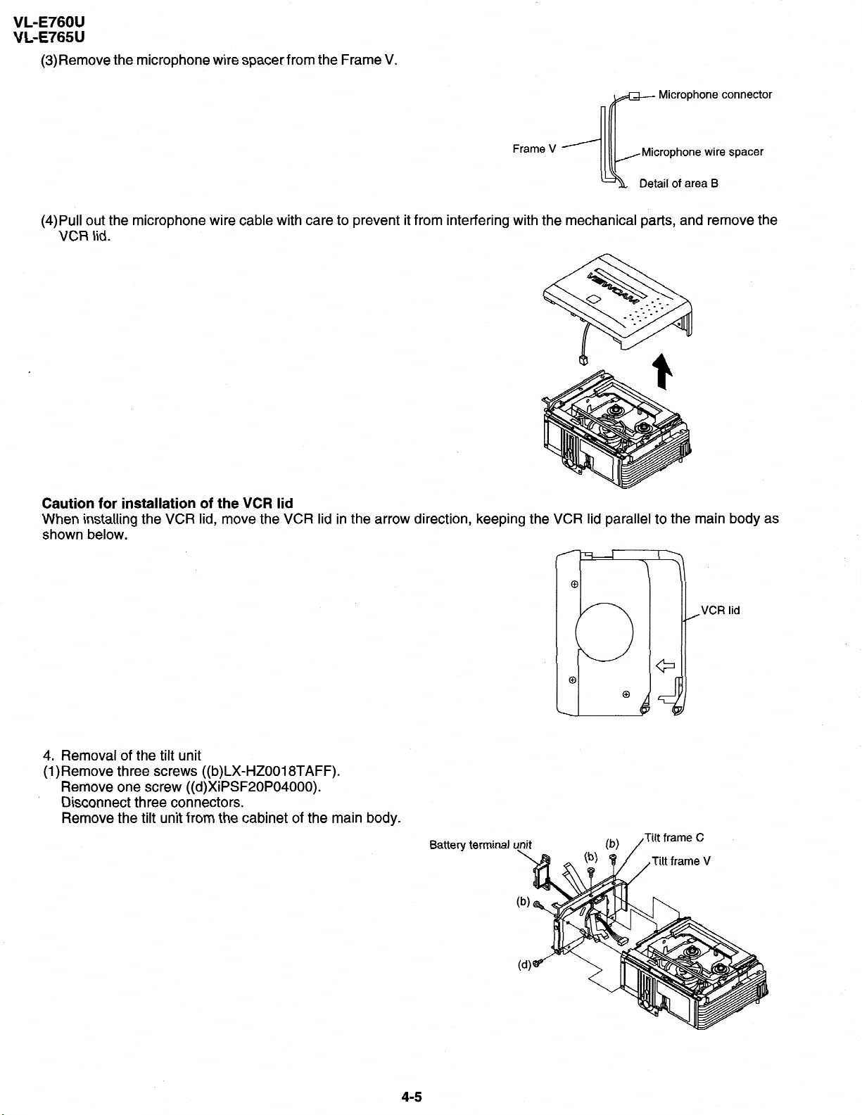
(3)Remove the microphone
wire spacer from the Frame V.
Microphone connector
(4)Pull out the microphone
wire cable
Frame V ’
care to prevent it from interfering with the mechanical
with
Microphone wire spacer
area
of
Detail
parts, and
remove
VCR lid.
Caution for installation of the VCR lid
When installing the VCR lid, move the VCR lid in the arrow direction, keeping the VCR lid parallel to the main
shown below.
_ _
B
the
bodv as
4. Removal of the tilt unit
(l)Remove three screws ((b)LX=HZ0018TAFF).
Remove one screw ((d)XiPSF20P04000).
Disconnect three connectors.
Remove the tilt unit from the cabinet of the main body.
Battery terminal u\nit
(b) /
,VCR lid
Tilt frame C
4-5
Page 13

VL-E760U
VL-E765U
5. Disassembly of the LCD holder
(l)Remove two screws ((d)XiPSF20P04000),
(2)Remove the
release its
remote
engagement.)
control ray reception PWB
Remote
control
angle.
pull
out the
tripod
Tripod angle
from the LCD, (Distorting the claw (snap-fit type) of
Remote
reception
ray
LCD holder,
the
control ray reception section
(3)Remove two screws ((b)LX=HZ0018TAFF)
and two
connectors, and
remove the LCD unit (with inverter) from the main
body.
LCD
rerter transformer
(4)Disconnect the connector which connects the
Li/RC unit to the main PWB, and slide the Li/RC unit in the arrow direction
from the frame V.
Note:
When connecting the FPC, pass it through the inside of rib of frame V (to prevent the FPC from being jammed).
LVRC unit
Frame V rib
Connector
46
I
Page 14
VL-E760U
VL-E765U
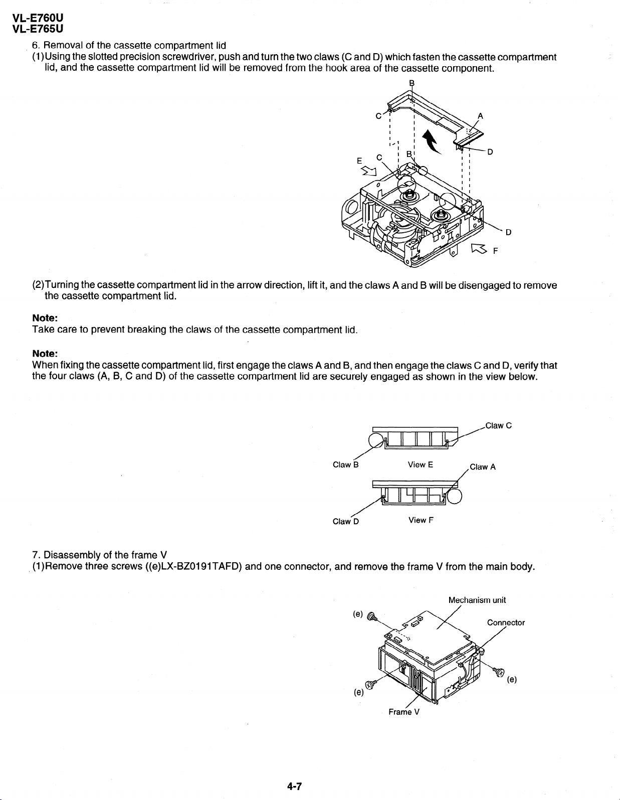
6. Removal of the cassette compartment lid
(l)Using the slotted precision screwdriver, push and turn the two claws (C and D) which fasten the cassette compartment
lid, and the cassette compartment lid will be removed from the hook area of the cassette component.
(2)Turning the cassette compartment lid in the arrow direction, lift it, and the claws A and B will be disengaged to remove
the cassette compartment lid.
Note:
Take care to prevent breaking the claws of the cassette compartment lid.
Note:
When fixing the cassette compartment lid, first engage the claws A and B, and then engage the claws C and D, verify that
the four claws (A, B, C and D) of the cassette compartment lid are securely engaged as shown in the view below.
Claw B
Claw D
View F
7. Disassembly of the frame V
, (l)Remove three screws ((c)LX-BZOlSlTAFD) and one connector, and remove the frame V from the main body.
Mechanism unit
47
Frame V
I
Page 15
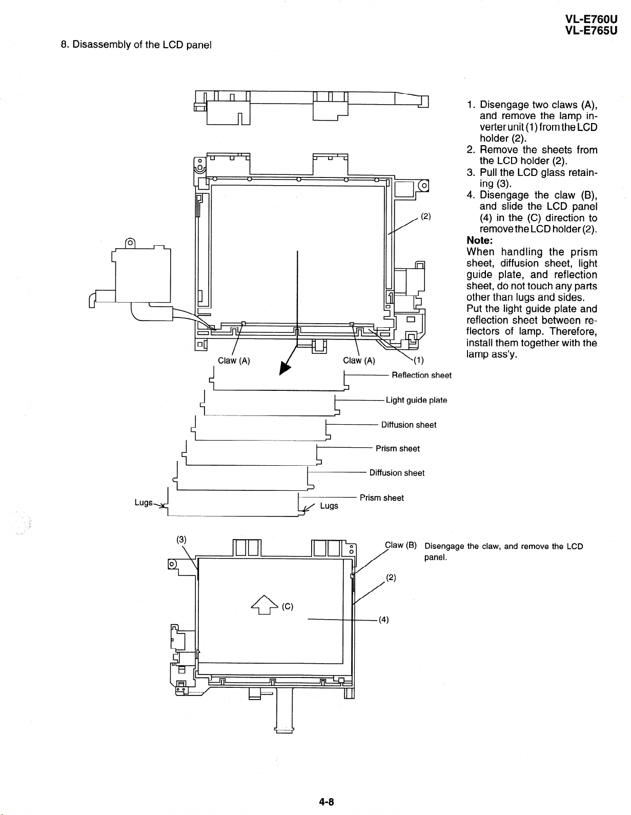
8. Disassembly of the LCD panel
I 1
I \
Claw (A)
Claw (A)
I- Reflection
\(1)
sheet
VL-E760U
VL-E765U
1.
Disengage two claws (A),
and remove the lamp inverterunit (1)from the LCD
holder (2).
2 *
Remove the sheets from
the LCD holder (2).
.
Pull the LCD glass retain-
3
ing (3).
4 .
Disengage the claw (B),
and slide the LCD panel
(4) in the (C) direction to
remove the LCD holder (2).
Note:
When handling the prism
sheet, diffusion sheet, light
guide plate, and reflection
sheet, do not touch any parts
other than lugs and sides
Put the light guide plate and
reflection sheet between reflectors of lamp. Therefore,
install them together with the
lamp ass’y.
,
(3)
Light guide plate
Diffusion sheet
- Diffusion sheet
Prism sheet
Claw (B) / Disengage the claw, and remove the LCD
I
I \,
panel.
48
I
Page 16

VL-E760U
WL-E765U
4-3. REPLACEMENT OF CCD SENSOR
4-3-l. BEFORE REPLACEMENT
1) The CCD image sensor is more sensitive to electrostatic breakage than CMOS LSI. Therefore sufficient means to
prevent electrostatic damage must be taken when it is replaced.
l Ground the soldering iron.
l Ground also the human body, using the wrist strap(through an 1 Mohm resistor).
l Until the CCDsensor is mounted on the PWB, fit it to the conductive,sponge, and short-circuit the foot lead.
2) Take utmost care so that the surface glass of CCD sensor and optical filter are not contaminated and damaged. If any
contamination is found, for example fingerprint, wipe it off with silicon paper or clean chamois skin.
3) When replacing the CCD sensor, use the antistaic grounded soldring iron, and perform quickly soldering.
Index Mark
Note:
indication of voltage (ofd) set value.
Voltage set value is indicated on the back of the CCD sensor.
V-OFD voltage marked on the back of CCD
4-3-2. REMOVAL OF CCD
1) Unsolder the CCD sensor leads from the sensor PWB.
2) Take out the sensor PWB.
3) Remove the two screws (6), and remove the sensor holder and CCD sensor.
1 7
1
0
h
14 8
LZ2413H5
YYWWXXX
4-3-3. MOUNTING OF CCD
1) Place the lens unit upright (since the CCD sensor mount ID faces upward, care must be taken so as not to damage the
front lens of unit), put the crystal filter first and then the dust protection rubber into the CCD holder of lens unit. Set the
crystal unit with its thin side toward the lens unit.
2) Place the CCD sensor so that the its No. 1 pin is at the right lower (Positioning hole to be at right), and put the CCD sensor
into the CCD holder. For smooth and tight fitting, press the right lower part of back of CCD sensor, and then press the
left upper part.
Note: Pay attention to the direction of CCD sensor.
3) Place the sensor holder so that its two round markings be visible, and fix the sensor holder with
HZ001 3TAFF).
4) Mount the sensor PWB so that the CCD sensor leads go thorough the PWB holes.
5) Solder the CCD sensor lead to the sensor PWB.
Note: Take care not to apply excessive heat.
Sensor Holder
CCD Sensor
I The mark mu
: this face.
I
_____--
st be on :
3
I
: The THIN SIDE :
: faces the lens
____________
:
Mark
I,__,,,,,,,,,,,,-
J
the two
I
I
I
I
I
I
screws
WLX-
Page 17

VL-E760U
VL-E765U
4-4. INITIAL SETTING OF E*PROM IC
4-4-1. E*PROM data alterable ways
Set the switch of main body to CAM, and use the remote control (RRMCG0033TASA) for adjustment to turn on the
1)
adjustment mode.
VCR adjustment address setting.
2)
V ADJ
00
After an objective address was established, play key is pushed and set.
In addition, numerical change uses a “REW” or “FF” key.
VCR adjustment data setting.
3)
4)
5)
V ADJ
00 ##
After an objective data was established, “PLAY” key is pushed and set.
When data of other address are changed successively, push “STOP” key, and please repeat operation to 5) from 3).
When SW of the substance is turned into off, data are written to E*PROM from systematic microcomputer.
4-4-2. IC702 (E*PROM)
When the IC702 has been replaced, make the following settings and adjustments.
1. Remove the backup battery (CR2025)
2. Turn power switch to CAMERA
3. Setting up the V ADJ mode as fotlows.
* After press the CONTINUE key, press the VCR ADJ key on service remote control (RRMCG0033TASA).
“00” is blinking
Value of “##” differs by an address.
4. After setting the above data, clear the V ADJ mode and turn off the power by pull out the battery pack or DC cable.
Neglect about 30 seconds after turned of power, because data of address becomes effective after microcomputer is
reset.
Now the setting of data is completion.
Adjustments to follow
Make the system controller servo, VCR, and LCD adjustments according to their respective instructions.
414-3. CAMERA ADJUSTMENT
When the IC2 has been replaced, make the camera adjustment according to its instructions.
All the camera adjustment data are written in the E*PROM provided on the lens unit. Therefore, when the lens is replaced,
the camera must be adjusted again according to the camera adjusting procedure.
4-5. ADJUSTING THE Y/C, AUDIO AND LCD CIRCUITS ON MODELS WITHOUT A/V IN MODE
(AA/ IN MODE SET-UP PRODUCE)
1) Set the switch of main body to CAM, and use the remote control (RRMCG0033TASA) for adjustment to turn on the
adjustment mode.
2) Set up the adjustment address (example : EEmode adjustment address 14). Once this address has been set up, the AA/
IN mode (test mode) is automatically brought and the images appear on the LCD display.
3) Now make the adjustments referring to the instruotions in the manual.
4-l 0
Page 18

VL-E760U
WL-E765U
5. MECHANISM ADJUSTMENT
5-I. Mechanism checking/adjusting jigs, tools and parts
5-1-1. Mechanism checking/adjusting jigs and tools
No.
1
2
Name
Cassette torque
meter for
PB
Cassette torque -
meter for VS-REW
3 Torque gauge
Part
JiG8T-012
JiG8T-032
JiGTG0045
No.
Code
Configuration
cv
cv . * ’
0
Q
Model, Uses Remarks
g.cm/25 g.cm)
(10
l
(50 g.cm/25 gem)
l
For measurement
l
8 Guide roller height
adjusting driver
Tu guide height
adjusting driver
9 Hex wrench(l.3mm)
JiGDRiVERHMX7U BU
SEQDRiVER-V712 BL
roller height
Si
Bit shape
(See the figure below)
TolerancefO. 1
/
w+
I+-A
25
02
8
se?
3
3
For loosening or
l
2
Edge
thickness 0.5
tightening of
Motor stator
51
I
Page 19

VL-E760U
VL-E765U
No . Name
Alignment tape
10
Tension Band and
Plate Adjusting Jig
12
Others
(1) Slide clippers
(2) High-precision screwdrivers (Phillips head, slotted head)
(3) Radio pliers (with thin jaws)
(4) A pair of tweezers
Part No.
VR2ABOPS
JiGDRiVERMX7Us BN
Zode
BT
Configuration
u
I
TAPE CONTENTS
1 VIDEO IMAGE 1
MONOSCOPE L-CH
llmtisi 30MIN I
Model, Uses
AUDIO
Remarks
1 TIME 1
5-l-2. Parts for periodic inspection and maintenance.
. Name Configuration
No
.
011
1
1) COSMOHYDRO HVIOO
2 Cleaning paper
Part No.
+
JiGDUSPER AP
Code
I-
3 Superfine swab
4 Grease
Morycoat YM-103/X5-6020
5 Screw locking agent
(1401 B)
6 Cleaning liquid
(Industrial-use ethyl alcohol)
Model, Uses
l Cosmo Oil Co., Ltd.
l Dusper C (Sigma)
(Ozu Co., Ltd.)
l Commercially available
item
l Dow Coaning
l Three Bond
5-2
Page 20

VL-E760U
VL-E765U
5-2. Items and timings of inspection
maintenance
and
The mechanism of VCR needs the
after the machine is repaired,
S-2-1.
Inspection and maintenance list
Checking/Maintenance
execute the following maintenance and checks regardless of how
point
Tape travelling route
Section)
to
(Refer
2
Drum (Refer to Section)
g
z
2
Video head
3
Fi?
3
Earth
brush
Timing belt
roller
Pinch
Capstan D.D. motor
F Relay Pulle shaft
Pulle gear shaft
3:
2
Drive gear shaft
$
cn
5
3
following periodic inspection
Usage time (hrs.)
and maintenance in order that it maintains its
Possible symptom
500 1,000 1,500 2,000 3,000 encountered
0 0 0
q
0
:f;;r;;;Eid
Screen shaking
0
0 III 0 Ll cl
0 00 0 [7() 00 *Improper
No color appears.
l
If significant brush
l
* * * * nobbing noise is
heard,
Tape does not run.
* - * *
q
0
0 00 0
l
Tape slackens.
l
Screen shakes.
l
replace.
- 0 - 0 0
Abnormal sound
A - A A
A - A A
l
S/N ratio
high quality.
long it has been used.
Remarks
Rollers
If abnormal rotation or
l
deflection (signifi-
is found, replace
cant)
roller.
the
Other than rollers’
@Clean the tape con-
Be sure
tatting
to use
cleaning
Replace if failure is
l
areas.
the specified
agent.
found.
Apply oil.
l
(Oil: COSMOHYDRO
HVI 00)
Note:
After oil is applied to
the drive gear shaft,
slightly wipe it off with
swab.
Also,
Loading motor
- *o - *o a
Abnormal sound
* * * * *
-II
% PBNS-REWtake-up torque - * - * *
g
2 PBA/S-REW back tension - * - * *
$ torque
(D
g Tu brake
* - * *
0 *
x HC (Head Cleaner)
Oil: COSMOHYDRO, HVl 00
Grease: MORYCOAT YM-103/X5-6020
0
0 0
0 : Replace.
q : Clean.
Screw locking agent: THERE BOND 1401 B
Cleaning liquid: Industrial-use ethyl alcohol
Replace if failure (ab-
Not ejectable
l
The specific mode can-
l
l
normal sound) is de-
not be set. tected.
If conformance to the
l
standard is not ensured, replace part.
A : Apply oil.
* : Check.
53
-
Page 21

VL-E760U
VL-E765U
5-2-2. Notes and cautions
(1) Any cut washers, once removed for parts replacement or for other reason, must be replaced with new ones.
(2)The mechanism of this VCR does not involve any volume adjustment. If the specified range is not satisfied, either
cleaning or replacing the parts is required.
(3) Oils
a) Be sure to use the specified oils (different viscosity may cause troubles).
b) For the bearings, be sure to use oil that is free form dust and other foreign substances. (Dust or foreign substance
contained in the oil may cause wear or seizure of the bearings.)
c) A drop of oil represents the amount of oil which is held on the needle top as shown in the figure below.
Oil
(4) The circuit repair must be executed without removing the V frame.
(5) For operating the mechanism alone, actuate it with the motor. The terminal-to-terminal voltage must be DC4V or less.
(6) When installing the cassette control, press the part A shown below. Do not press other parts.
(7)Take care so that the whole mechanism is not deformed.
Figure 1
5-4
Page 22

VL-E760U
VL-E765U
5-3. Mechanism checks and adjustments
The description given below relates to the general field services, but does not relate to the adjustment and replacement
that require high level equipments, jigs, and technical skills.
In order to maintain the initial characteristics of the machine, it is necessary to execute the maintenance and check and
to prevent damage to tapes and other parts. For adjustments which need jigs, be sure to use the jigs.
Notes and cautions
(1) For mechanism checks and adjustments, be sure to use the AC adapter as the power supply.
(2) For running the tape, be sure to install the cassette control ass’y in advance. (if the cassette control ass’y is to be
removed subsequently after its installation)
5-3-l. Checking the reel disk height
(1) Remove the cassette control ass’y.
(2) Taking due care not to let the master plane touch the tape running areas such as the drum and the guide rollers,
position the master plane so that the two guides (A and B in the figure 1) are set in the holes of master plane, then
properly set it in the mechanism.
B-
Figure 1
(3) Using the slide callipers or the like, check that the distance from the upper surface of master plane to the reel support
surface of the S/Tu reel disk is within the specified range.
Note:
When measuring, do not apply excessive force to the reel support surface of reel disk.
(4) If the measurement is not within the specified range, replace the reel disk ass’y.
(5) Check the items (2) to (4) above in the following two modes.
a) Standby mode
b) Playback (recording) mode
Figure 2
I
55
Page 23

/
VL-E760U
VL-E765U
5-3-2. Checking the take-up torque for playback (recording)
(1) Set the torque cassette (8T-012) in position, and check in the SP-mode recording mode (tape recorded in SP mode)
that the torque at the tape taking-up side is within the standard range.
Standard of take-up torque for SP-mode recording (playback)
9 + 3 g.cm with ripples less than 4 g.cm
(If the torque ripples appear, read the center value of torque between the ripples.)
5-3-3. Checking and adjusting the back tension torque for playback (recording)
(1) Checking
1) Set the torque cassette (8T-012) in position, and check in the SP-mode recording mode (tape recorded in SP mode)
that the torque at the tape supply side is within the standard range.
Standard of back tension torque for SP-mode recording (playback):
8 + 2 g.cm with ripples of less than 2 gem
(Torque ripple must be within 8 & 2gcm)
(2) Adjustment
1) If the back tension torque is not within the standard range, adjust the tension spring hooking position. If the back
tension is too high, hook the spring in the direction A. If the back tension is too low, hook the spring in the direction
B .
Note:
1. After back tension torque adjustment be sure to check the tension pole position”
5-3-4. Checking and adjusting the tension pole position
(1) Check
When winding of P6-120 tape is started, check whether the tension pole is in the specified position against Si roller
as shown or not.
If it is not in the specified position, remove the cassette and adjust the position in the following procedure.
(2) Adjustment
(2)-l. Don’t set up any tape, and select the PB mode. (Refer to Item 5-5-l-(4).)
2. Slightly loosen the screw (1) (to such a strength as the T band holder B can be moved).
3. If the tension pole is in the inner position than specified, dislocate the T band holder B in the arrow (A) direction
and if it is in the outer position, dislocate it in the arrow (B) position. Then, tighten the screw (1). (For reference,
dislocate it 0.4 to 0.8 mm outer from the position specified above.) For the position adjustment, it is convenient
to use the position adjustment screwdriver (JiGDRiVERMX7U2). (Set it in the hole (C).)
4. Check the position in the “(1) Check” procedure described above.
5. If it is not in the specified position, repeat the adjusting procedure 1 thru 3.
5-6
Page 24

VL-E760U
VL-E765U
Note: .
*Tightening torque of screw (1) 70 mN*m
.To check the position, be sure to run the tape.
l If the cassette compartment assembly is removed, it makes the work easier. (Refer to Item 5-5-3.)
T
H
5-3-5. Checking the take-up torque for rewind playback (VS-REW)
(1) Remove the cassette compartment ass’y and set to the sensor OFF mode.
(2) Set the torque gauge (TG0045) on the S reel disk, and check in the rewind playback (VS-REW) that the torque at
the supply side is within the specified range.
Standard of take-up torque in rewind playback (SP mode)
31 + 5 gem with ripples less than 5 g.cm.
(If the torque ripples appear, read the center value of torque between the ripples.)
5-3-6. Checking the back tension torque for rewind playback (VS-REW)
(1) Set the torque cassette (8T-032) in position, and check in the rewind playback (VS-REW) mode that the torque at
the tape take-up side is within the specified range.
Standard of back tension torque in rewind playback (SP mode):
14 + 5 gem with ripples less than 5 g.cm
(If the torque ripples appear, read the center value of torque between the ripples.)
5-7
Page 25

5-4. ADJUSTMENT OF MECHANISM TAPE TRAVEL SYSTEM
Sup tilted pole
I
Tu tilted pole A
Tu GR
VL-E760U
VL-E765U
Tu guide
Tape travel system (Figure 1)
5-4-l.
Preparation for adjustment
(1) Clean the tape running areas (guide poles, rollers, drum, Capstan shaft, Pinch roller) (Figure 1)
(2) Connect the oscilloscope to the following TPs.
RF output . ..TL3306
H-SW-P
. . . . ..TL405
GND . . . . . . . . . . . TL3318
(3) Playback the alignment tape (VR2ABOPS).
(4) Ascertain that each guide is free from remarkable curl.
(5) Ascertain that the RF waveform of inlet and outlet sides is flat on the oscilloscope (Figure 2, (a)). Unless the waveform
is flat, (Figure 2, (b), (c)), make an adjustment as follows.
5-4-2. Adjusting the Sup GR and Tu GR
(1) Turn the Sup and Tu guide rollers to get the flat waveform at the inlet and outlet sides.
Inlet side
+-+ (a) Normal
Outlet side
(c) Outlet side
waveform is disturbed.
Figure 2
S-8
Page 26

VL-E760U
VL-E765U
S-4-3. Adjusting the Si roller height
After replacement of Si roller preset and adjust the Si roller height.
(1) Si roller height presetting
Adjust the height from the upper surface ofmechanism chassis to the upper surface of lower flange with the aid of jig.
Then lower it by 90’ (clockwise).
(2) Adjusting the Si roller
Playback the thin tape such as P6-120MP to set the V/SR mode.
Ascertain that the tape is not folded on the lower flange (2) of Si roller (1). (Figure 4)
If tape folding is found, turn the upper flange (3) of Si roller (1) with the driver (clockwise) to eliminate the folding.
Upper flange
Figure 3
Height adjusting jig
Master plane
Playback the alignment tape (VR2ABOPS).
Adjust the Sup GR and Tu GR by the procedure described in section 4-2 above.
After V/S F,R perform playback so as to ascertain that the waveform rises horizontally within 2 seconds.
Unless the normal waveform is obtained (Figure 5), turn counterclockwise the upper flange (3) of Si roller (l), and
repeat the step (5) above. Repeat the steps (5) and (6) until the normal waveform is obtained. At this time ascertain
that the inlet travel does not change in the normal playback state. If any change is found, adjust the Sup GR, and
redo the step (5).
Rise waveform
Playback
Upper flange (3)
Tape must be free from foldeng.
Si roller (1)
Figure 4
REV
kZ&
REV NG
Figure 5
5-4-4. Adjusting the Tu guide
After replacement of Tu guide preset and adjust the height.
(1) Tu guide height presetting
Adjust the height from the upper surface of mechanism chassis to the upper surface of lower flange with the aid of jig.
Upper flange
i-
/eight setting iig Master p,ane
(JiGMP-MX?U)
I
Lower flange
Figure 6
5-9
Page 27

(2) Adjusting the Tu guide
,*
1 Playback the Tu guide adjustment cassette (or the No.7 guide adjustment cassette for E30).
2 Check that the tape runs at the same height near the capstan shaft in case of V/S F and V/S R.
3 If the tape running position in case of V/S R is higher than the tape running position in case of V/S F, turn clockwise
the Tu guide nat.
If the tape running position in case of V/S R is lower than the running position in case of V/S F, turn counterclockwise
the Tu guide nat.
Capstan shaft
Pinch r
‘II ’ //
Figure 7
5-4-5. Checking the V/S F and R waveforms
Playback alignment tape (VR2ABOPS), and set the V/S R mode. At this time ascertain that the waveform crest pitch
is kept constant for more than 5 seconds.
VL-E760U
VL-E765U
Set the V/S F mode. At this time ascertain that the waveform crest pitch is kept constant for more than 5 seconds.
Unless the constant pitch is obtained, execute the checks of Section 4-2, 3, and 4.
t”T”T”T”i
Figure 8
5-4-6. Checking after adjustment
(1) Envelope check
1 Playback the alignment tape (VR2ABOPS).
2 Ascertain that the envelope maximum to minimum ratio is 65% or more. (Figure 9)
3 Ascertain that the waveform does not change remarkably. (Figure 10)
_ EMIN
Figure 9
Erhx
EMIN
- > 65 (%)
EMAX
C’ll8A
Figure 10
5-10
Page 28

VL-E760U
VL-E765U
(2) Rise check
1 Playback the alignment tape (VR2ABOPS).
2 Once eject the cassette, and then load it again.
3 Set the playback mode, and ascertain that the RF waveform rises horizontally within 2 seconds. At this time ascertain
that there is no tape slackness near the pinch roller.
4 After V/S F, R and FF/REW execute playback, and ascertain that the RF waveform rises horizontally within 2
seconds. At this time ascertain that there is no tape slackness near the pinch roller.
Tu
cl’
GR
Figure 11
(3) Checking the tape travel
1 When the thin tape such as P6-120MP is played back, ascertain that tape lift and tape curl of 0.3 mm or more do
not occur at the lower flange of Si roller, upper flange of Sup GR, upper flange of Tu GR, and upper/lower flange of
Tu guide.
2 In case of V/S F and R ascertain that no curl is found at each flange.
Tension pole
Tu GR
Sup tilted pole
4
Figure 12
5-4-7. Checking and adjusting the playback switching point
Refer to the description of playback switching point adjustment in section of VCR circuit adjustment.
5-l 1
Page 29

5-5. Mechanism assembling and parts replacement (disassembling and assembling)
Below is given an explanation of assembling of mechanism and its parts replacement.
The removal of cabinet and Circuit Board is explained in the relevant service manual.
Notes
After removal of cut washers be sure to replace them with new ones.
Do not place the mechanism upside down on the table. Otherwise, the mechanism part may be deformed or
damaged, resulting in malfunction.
When assembling, take care so that screw, washer or other foreign substance do not enter. Otherwise mechanism
malfunction may occur.
Be sure to use the specified cleaning liquid, oil, grease and screw lock as listed below. Otherwise mechanism
malfunction may occur.
Oils: 1) Cosumo Oil Co., Ltd.
COSMOHYDRO HVI 00
Greases: Dow Coaning
MORYCOAT YM-103/X5-6020
VL-E760U
VL-E765U
Screw lock: THREE BOND
1401B
Cleaning liquid: Industrial-use ethyl alcohol
5-5-l. Mechanism modes
To actuate the mechanism, apply DC3 to 4V to the L motor ((2) in Figure 4). At this time the L motor connector must have
been disconnected in advance.
Below is given an explanation of the mechanism mode necessary for mechanism check, adjustment and replacement.
(1). -1 mode (See Figure 1)
In this mode, it is mechanically positioned to eject the cassette. It is the position where the EJECT lever is moved the
farthest in the direction A in the S/B mode. (In this mode, the cassette compartment assembly can not be locked.)
Slide
chassis
EJ mode
0
Figure 1
5-12
Page 30

VL-E760U
VL-E765U
(2).-l mode (See Figure 2)
When the cassette is loaded, the mechanism is set to the S/B mode. In this mode the slide chassis is most far from the
drum. In this mode the Eject lever is in position shown in Figure 2 (in position where the cassette control ass’y can be
locked).
(3). 1 STOP 1 mode (See Figure 3)
EJECT
Lever
Slide
chassis,
S/B mode
I
Figure 2
In the STOP mode the S.
the S brake is in contact
T pole base is depressed in the STOP position (or
with the S reel disk.
S pole base
S re’el disk
\
S brake
pole_ base
T
Ret Lock position in CAMERA mode), and
STOP mode
Figure 3
(4). l=lrnode (See Figure 4)
In this mode, it is positioned for the replay, record and so on. It is the mechanical position
against the capstan shaft to make the pinch-pressing spring the most longest.
Pinch roller
Camtan
- --I- - ----
sQaft
where the pinch roller is
\
pressed
PB mode
I
Figure 4
5-13
,Pinch
Spring
Page 31

VL-E760U
VL-E765U
5-5-2. Cassette control ass’y
<Disassembling>
(1) Set the unit to the EJECT mode, and let the housing stand upright. Or set the unit to the STANDBY mode, press the
lock lever in the arrow direction, and let the housing stand upright. (See Fig 5: in the direction @ or @) (When pushing
in the direction @, slightly lift the housing by hand to release the lock lever.)
(2) Remove the four screws @ and take out the down guide 0.
(3) Slide the two link support shafts @ and the two roller shafts @ to the round openings @ on their respective slide
chassis slits (two at @ and two at 0).
(4) Deflect the roller shafts @ a little inward to get them out of the round openings @ on the slide chassis. (Be careful
not to deform the inner links.)
I Figure 5. Lock lever section
Q
Lock Lever
.
Down Guide
i
-It-O
Screw tightening
torque (4 locations)
0.069f0.007 Nom
(0.7f0.07kgcm) (
<Reassembling>
d
d
Figure 6.
(1) Set the unit to the STANDBY mode.
(2) Deflect the roller shafts @ a little inward, and fit them into the round openings @ on the slide chassis. (Be careful
not to deform the inner links.)
(3) Align the flanges of roller shafts @ with the slide chassis slits 0. While sliding the flanges, fit the support shafts @
in the slide chassis slits @, and slide them until they reach the slits.
(4) Attach the down uide. (While pressing the guide in the direction 0, tighten the screws until the gap 0 between
the down guide 3 and the support shafts @ becomes zero.)
Tightening torque: 701t7 mN*m (0.7kO.07 kgcm)
Q
5-14
Page 32

VL-E760U
VL-E765U
5-5-3. Actuating the mechanism with the cassette control ass’y removed
(1) Turn on the power supply with the cabinet and camera unit removed, referring to the Service Manual (so as to actuate
the mechanism).
(2) Put the cap (2) on the light guide (1).
(3) Press the cassette control down switch (5) through the adhesive tape (4) in the arrow direction so as to turn it on.
At this time take care to avoid contact with the cassette. Keep the switch pressed (if the switch is turned off, unloading
occurs).
Note: To set the Ret mode, press the pin (marked with the asterisk *) of recognition switch (3) (this operation is not
necessary in other modes).
Cap (2)
0
Cassette control down s
5-5-4. Drum and Drum base
Removal
* To replace the upper drum, be sure to put on gloves. Due care is required so that the drum is not damaged.
(1) Drum base
Remove the 3 mounting screws as shown in Figure 1, and remove the drum base.
Mounting screw
Figure 1
5-15
Page 33

(2) Drum motor stator
VL-E760U
VL-E765U
Remove
the
stator
(3) Upper drum ass’y
Remove the upper drum
At this time take care so
mounting
screw
Stator
Upper/lower
with
the hexagonal wrench
drum
ass’y
Figure 2
as
Phase matching
A
\
ass’y from the lower drum ass’y as shown in Figure 3.
as not to lose the gap shim.
1
shown in Figure
hole
2, remove
the
motor
stator.
Lower drum
:
(4)
. .
Motor rotor ass’y and rotary transformer rotor ass’y
Remove the
2
rotor mounting screws as shown in Figure 4, and remove the motor rotor and the rotary transformer ass’y.
Rotor mounting screw
.~I
ass’y
Figure 3
drum ass’y
Figure 4
5-16
Page 34

VL-E760U
l/L-E765U
(5) Balancer
Remove the balancer mounting screw as shown in Figure 5, and remove the balancer.
(6) Lower drum ass’y
Remove the FPC mounting screw from the lower drum ass’y as shown in Figure 6.
Balancer mounting screw
.
Balancer
Jzr
Upper drum ass’y
Figure 5
FPC mounting screw
Lower drum ass’y
Figure 6
Installation
Install the upper drum in the reverse order of removal.
(1) Balancer
Mount the balancer to the upper drum ass’y with the balancer mounting screw. The screw tightening torque must be
0.1 N*m (tighting torque 1 kgcm). (Figure 5)
(2) Motor rotor, rotary transformer rotor ass’y
Clean the contact surfaces of rotor ass’y holder and upper drum ass’y, and ascertain that there are no contamination
and flaws.
Next, adjust the phase so that the positioning pin of rotor ass’y is inserted into the positioning hole of upper drum, and
tight fit the rotor ass’y to the lower surface of upper drum ass’y (Figure 7).
Rotary transformer
Mounting screw hole
Rotary transformer
rotor
k
area)
Rotor ass’y
A Positionina hole
To be aligned with
RTr rotor side position
Cleaning
pin.
Figure 7
547
Page 35

state put the motor rotor on the upper
this
In
make sure
that the head screw in
torque must be 0.1 Nom (1 kgcm).
transformer
Rotary
surface of upper
three places is visible through
the
mounting screw
Rotor
Head mounting
drum ass’y, and tighten the mounting screw.
motor rotor hole (Figure 8). The screw tightening
the
ch
L
VL-E760U
VL-E765U
At this time
Figure 8
(3) Lower drum ass’y
Tighten the FPC mounting screw to the lower drum ass’y.
The screw tightening torque must be O.O8N-m (tighting torque
0.8kgcm). (Figure 6)
(4) Upper drum ass’y
After fitting the gap shim which was removed when the upper drum ass’y was dismantled to the shaft of
ass’y, fit the
At this
upper drum ass’y. (Figure 3)
time slightly
turn the
upper drum ass’y by hand to
ascertain that RTr does not scrape. If scrape is found, replace
the gap shim with the gap shim packaged together with the replacement upper drum ass’y.
(5) Drum motor stator
Fit the motor stator to the shaft. Then, apply the
tightening torque must be 0.15N.m (1 Skgcm).
stator mounting screw.
The
preliminary pressure 0.07N.m (0.7kg) to the motor stator, tighten the
Install the stator so that the chassis line is nearly parallel with the motor stator straight section when it
the chassis. (Figure 9)
(6) Drum base
Align the positioning pin, and tighten the screws (3 PCS.).
Motor stator
line
Arrange
Chassis
FPC /
parallel.
lower drum
is installed on
Figure 9
5-18
circuit board
Page 36

VL-E760U
VL-E765U
(7) Drum ass’y
Install the drum ass’y on the main chassis, and tighten the screws (3 PCS.).
(8) Tape guide
Align the positioning pin, and tighten the screw (one PC.).
5-5-5. Phase matching
The phase of the following parts must be matched as shown in the figure below.
(Ascertain that the A marks and round holes align.)
(1) Lo relay gear (2) Main cam (3) Sub-cam
Lo relay gear
Phase alignment marl
(Round hole)
(4) Mode switch
Phase alignment mark
(AMaW
- Mode switch
Phase alignment mark
(Round hole)
5-6. MECHANISM ASSEMBLING METHOD
(1) Adjust the phase of each part.
(2) Install screws and washers.
(3) Install the segment gear, T arm guide and the M-function lever. Install the eject lever.
B
Item
a S Tight Ml .4 x 3
B 00.8-03.0-to.2
a
Tightening torque
70mN.m (0.7kgfcm)
Quantity
1
1
5-l 9
Page 37

VL-E760U
VL-E765U
(4) Install the loading block assembly and the capstan motor.
(5) Install the drive gear. At this time, pay attention to the direction of gear. (The small gear must be located in the chassis
side.)
, Install the
motor under
this plate.
Item Tightening torque
A S Tight Ml .4 x 2.5
a S Tight Ml.4 x 3
70mN-m
70mN-m
Quantity
1
4
Position the small gear ot the drive towards
the chassis.
(6) Install the guide rail assembly.
Insert the
and slide
Make sure not to
deform the arm.
part in the rail
it down.
Page 38

VL-E760U
VLcE765U
(7) Install the guide rail assembly taking care to position it correctly.
Item
A S Tight Ml .4 x 2.5 70mN.m
B S Tight
Ml .4 x 4 40mN.m 1
Tightening torque
1 C I00.8-03.0-to.2 1
B
1 D I02.1-&X0-to.25 l
a 1 S Tiaht Ml .4 x 3
Tot deform the arm.
Align the marks on the parts.
70mN*m
1
Quantity
2
I 1 I
I 1 I
I 1 I
Square Hollow Mark
\
/
Segment gear
Su arm Ass’y
Triangle Mark
/
T Lo arm Ass’y
5-21
Page 39

(8) Install the drum assembly in the chassis.
(9) Install the tape guide in the drum assembly.
(10) Install the Si roller.
VL-E760U
VL-E765U
Item Tightening torque
A S tight Ml .7 x L5.3
B S tight Ml .7 x L2.5
Quantity
1 OOmNom
GOmN-m 1
3
Tape guide
A
Drum asset
nbly
/
Chassis drawing
5-22
Page 40

VL-E760U
VL-E765U
(11) Install the slide chassis.
T arm guide
/
/
\
Item
A Ml
.4 x 1.5
B Ml .4 x 1.5
Tightening torque
04.0 40mN.m
03.5 40mNom
Quantity
1
3
I
\
Main cam pin
r
1
r\ @ I\
I
\
,)
0
- Sup reel base
1
B
-92 +
:::::::::::~.~.::::::::::::~:~:~:
. . . . . .
. .
. . . . . . . . . .
. . . .
. . . . . . . . . . . . . . . . . .
. . . . . . . . . . . . . . i....,.................
::::::::::::::::::::j:::::::::::~:::::
. . . . . . . . . . . . . . . . . . . .
..i::::::::::::::::::::::::::::::::::::.
.I............................,..
@ /
i:.::: i....... :.:sk:c
Slide this part towards the T arm.
Place the slide chassis
on the guide rail.
I
. . . . . .
. ..C.
. . . . . . . . . . . . . . . . . . . . . . .
. ..i................
. . . . . . . ..i..........
0
. ..::::::
. . . .
. . . . . . . . . . . . . . . . . . . . . . . .
. . . . . . . .
. . . . . .
~.‘.~.~.~.iSS~.~.~.~.....~..
i...........
#:~~~:~.~~.:~:~~.~:~:~:~:~:~:~~:~:~
:::::::::::::::::::::::::::::::::::::::::::::::::
.~:.~:.:.:.:.:.:.:.:.:.:.:.:.:.:.:.:.:.:.:.:.:.
:::::::::::::::::::::~::::::::~:~:::~:~:~y~:~:
. . . ..i.... . . . .
. . . . . . . . . . .
. . . . . . . . . . . . .
. . .
. . . . . . . . ..i........ . . .
. ..i..................
. . . . ..s.....‘...r..........:.:.:.:.:.:.~.:
..:::::::::::::i::::::::~.:.:.:.:.:.:.:.:.:.:.:.:.
. ‘.:.:.:.:.:.:.:.:.:.:.:.:.:.:.~.:.:.:.:
. . . . . . . . . . . . . . . .
..-. . . . . . . . . . . . . . . .
. . . . . . . . . . . . . . . . .
. ..i . . . . . . . .
. . . . . . . . .
. . . . . ..P....
. . . . . . . . . . .
. . . . . .
. . . . . . . . . .
’ Insert the main cam pin into the hole of
cam of slide chassis.
. . .
. .
. .
. .
J/
.
A
AL
5-23
Page 41

.
(12) Install in the following order: T guide lever spring, T guide lever, pinch lever.
(13) Install the swing arm.
(14) Install the right guide holder.
A S tight Ml .4 x 2.5
B CW 00.8-03.0-to.2
Item Tightening torque
Tu
70mN.m
70mN-m
Pinch lever
Tu guide lever SPR
Attach to hook
VL-E760U
VL-E765U
Quantity
1
1
Attach to hook
Swing arm
Take care of position.
4
Pinch lever
The pinch lever
is positioned on
the stopper.
1
DB
Secure on back side
Take care not to bend the tension band
during assembly or disassembly.
I
5-24
Page 42

VL-E760U
VL-E765U
6. ADJUSTMENT OF VCR
6-1 l ADJUSTMENT OF VCR SECTION 6-1-1 l Before starting the electric circuit adjustment
l Electric circuit adjustment becomes necessary, in most cases, when any of the wear mechanical parts or the video head
has been replaced. Before starting the electric circuit adjustment, be sure to check that the mechanical parts work well
(i.e., the mechanical parts have all been perfectly adjusted). In case a trouble or troubles are found in the electric
circuitry, be sure to pinpoint the cause(s) by using the measuring instruments described below. After locating the trouble
spot(s), then proceed to repair, replacement or adjustment. Do not change the positions of the controls when adequate
measuring instruments are not available.
l In order to implement a higher-density, smaller machine, most of the electric circuit parts used on the Circuit Boards
are of small-sized, surface-mounted type. For replacing part(s) as after-sales service, work with a soldering iron as
speedily as possible. The heat resistance of the surface-mounted components is poor, when compared with the largersized discrete parts used for television sets and stationary decks, owning to their small sizes. Therefore, exercise due
care to avoid long-time exposure of the pins of these parts to the heat of the soldering iron which may possibly damage
them. Such care should be exercised especially for chip-layer capacitor replacement. It is advisable to use a
temperature-controlled ceramic soldering iron (temperature at the tip: 250°C, contacting time: less than 5 seconds).
< Adjusting the video/LCD section >
l Measuring instruments:
*Color monitor TV set
*Digital voltmeter
*DC power supply
*Audio generator (CR oscillator)
*Alignment tape (JIGWRS-SNSP)
*AC adapter
*AV output cable (accessory)
*Oscilloscope *Vector scope
*Frequency counter
*Signal generator (NTSC pattern generator LCG-401/401 YC: Leader-made)
*Video recording tape
(For Y/C, audio and servo adjustments)
*DC cable (AC adapter accessory)
*Video extension cables
6-l
Page 43

6-l-2. Servicing the VCR section Adjustment 6-1-2-l. Typical connections
Extension Cable etc.
VL-E760U
VL-E765U
NO . NAME
1 Extension Cable Inverter-VCR (7pin)
2
Extension Cable Camera-VCR (17pin) QCNW-1380TAZZ BD
3 Extension Cable Camera-VCR (1 Spin) QCNW-1311 TAZZ BA
Extension Cable MECHA-VCR (70pin) QCNW-1534TAZZ BS
Extension Cable LCD-VCR (24pin)
Operation Unit
7
1 Connector fitting and withdrawina
1 extractor
8 I Connector fitting and withdrawina
9
Service remote control
1
PART NO.
QCNW-1265TAZZ AX
QCNW-l382TAZZ BD
QSW-Z0287TAZZ AR
I\
I9EQPiNSETc
RRMCG0033
I
I
Code CONFIGURATION REMARKS
4
a
c
ii
I
I
- VbM I
UNIT ’
.- 0
OPERATION
UNIT
\ CAMERA
UNIT
uu
_ocl
3
6-2
Page 44

VL-E760U
VL-E765U
l Types of test modes
TEST No.
Title
Contents
Sensor on/off
1 Sensors off All sensors but the cassette controller switch, dew sensor
and battery sensor stay off.
3 Automatic battery sensor Battery sensor’s input voltage put in memory.
adjustment
4
Battery adjustment error Battery sensor’s adjustment errors are displayed at the
display right of the “past errors” area.
I I
5 1 PASS mode ITrack shift mode (l/4 shift)
I
6
Camera adjustment mode Camera adjustment mode
All sensors on
All but sensors
on
1 All sensors on
[VCR
interrupted]
7
VCR adjustment mode
VCR adjustment mode
8 Automatic switching point Play standard tape and call this mode. Switching point is
adjustment (STOP ADJ)
automatically adjusted.
@ When the battery adjustment mode is selected from the camera adjustment mode with a cassette with the erase
protection tab, the VCR is automatically put in the REC mode.
l Below discussed are these seven test modes.
@) jTEST No. I] Sensors off mode
All the sensors, except for the cassette controller switch, dew sensor and battery sensor, stay off. This
enables to bring the VCR in the loading mode without tape. The VCR/camera performance can now
be checked with no tape inside.
1
@ [TEST No. 31
Automatic battery alarm adjustment
Used to automatically adjust the voltage level which makes the “battery” appear on the LCD display.
@ [TEST No. 41 Battery alarm check/error display
l The difference between the preset battery alarm voltage and the current supply voltage is displayed
as follows.
l A past error is displayed at the right of the current battery alarm error.
@ [TEST No. 51
PASS mode
Used to adjust the tape travelling condition. The tracking is shifted by l/4 from the center to make the
tape running-related RF envelope fluctuations easier to observe.
@ [TEST No. 61
Camera adjustment mode
Used to adjust the camera section. (For details, see Servicing the Camera Section.)
@ [TEST No. 71
VCR adjustment mode
Used to adjust the VCR section. (For details, see Servicing the VCR Section.)
@ [TEST No. 81
Automatic switching point adjustment
Used to automatically adjust the playback switching point. (For details, see Automatic Adjustment of
the Playback Switching Point.)
6-l-2-2. Setting up the VCR section adjustment mode (camera section adjustment)
0 Select adjustment items by using addresses. Rewrite the adjustment data to change the settings.
Below shown the adjustment procedures and on-screen display.
“--__‘.---______‘_-,
Enlarged view
(CAM ADJ) camera -----
V ADJ+VCR,%D
00 00
(Address) (Data)
VADJ;
00 i
.-_________________a
T-07
6-3
Page 45

VL-E760U
VL-E765U
Procedural steps
w Turn up or down the flashing hexadecimal number with the FF or REW key to select the
Display
( : flashing)
V ADJ
address of a desired adjustment item. (Initial address: OOH)
Note: The addresses change as follows.
@
Press the PB key to read the data of the selected address.
7E - 7F - 00 - 01 - 02
V ADJ
2C A3
Turn up or down the data setting with the FF or REW key. The data display starts flashing.
V ADJ
2c
@ Press the PB key again to write the data setting into the selected address.
V ADJ
2C 72
@ Press the STOP key in the above step @ or @, and the screen returns back to the step 0.
V ADJ
When the FF or REW key is held down for 0.3 second or longer, the address selection is repeated in cycles of 100 msec.
The data setting changes by + 4 by holding the key down for 2 seconds or longer.
6-1-2-3. Battery shut-off voltage adjusting method
Supply power to the main unit, using the variable-voltage DC power supply (range of 2.5V to 5V).
1)
Set the CAM/OFFA/CR SW to CAM to switch to the camera mode.
2)
Load a recordable tape and set the main unit to CAM REC. PAUSE.
3)
Set the main unit to TEST mode No. 3, and start recording.
-I
4
Measure voltage between TL901(+) and TL903(GND), and adjust the supply voltage to 3.OV.
5
The adjustment is complete if “BATTERY” is displayed on the monitor screen for a second when the PLAY key of
6
operation unit is pressed.
The adjustment is regarded as proper if the auto shut-off is actuated after the warning is displayed when the TEST mode
is cancelled.
__
In case of automatic adjustment of shut-off voltage, adjustment is impossible if voltage is above 3.OV + 0.2V.
If the adjustment is made at 2.9V or below, the low-voltage operation may become unstable.
l Types of test modes
Any of the eight test modes can be set up by changing the input voltage at pin (54) of IC703. During any test mode, the
REC Start/Stop commands are not accepted.
5v
1.2k 1.5k 2.2k 3.3k 5.6k 10k 33k
Use the SW2 thru SW9 switches on the adjustment tool to select the following test modes.
SW No. Title Contents
2 Sensors off
3
4 Automatic battery sensor
5 Error display
6 PASS mode Track shift mode (l/4 shift)
7
8 VCR adjustment mode
9 Automatic switching point
Mechanism adjustment mode
adjustment
I --v-B
Battery adjustment error drsplay Ba%@ensor s adjustmentTr= are drsplayed atherigm ofihe -
Camera adjustment mode Camera adjustment mode
adjustment (STOP ADJ)
-v-111)
All sensors but the cassette controller switch, dew sensor and battery
sensor stay off.
@ Automatic SP/LP detection prohibited
Q Different-mode detection prohibited
0 ATF sampling limited to center
Battery sensor’s input voltage put in memory.
Past errors appear on the counter display of the viewfinder.
“past errors” area.
VCR adjustment mode
Play standard tape and call this mode. Switching point is automatically
adjusted.
-Iv--
Adjustment tool
-v--
Sensor on/off
All sensors on
All sensors on
All but sensors
on
All sensors on
[VCR
interrupted]
@ When the battery adjustment mode is selected from the camera adjustment mode with a cassette with the erase
protection tab, the VCR is automatically put in the REC mode.
I
64
Page 46

VL-E760U
VL-E765U
6-l-3. Adjusting the VCR
Points on the
Test
0
circuit
Video Circuit
Board
o_TLaa25
I++
1
nn
0
rL613,,9000
TL606-0
o_TL 607
TL609====+
o_TL60
601-O
TL
602=+00
604-
Gb
0
1
m
0-J
c
o_TL709
o_TL713
o-TL716
o_TL701
_TL706
o_TL97050+--TL946
o_TL9704
o3 oe-TL941
0
El
r-
cn
a,;;;
22
0_TLaa27
o_TL940
TL947-0
O-
IL905
o_TL937
TL913-o"
TL925-0
O_TL932
TLaalO-p
TLaal9-00
TLaa14
TLaa13
TLaali-+000
;;g;;-c
TL1925-00 02
TLaa09-00
TL97154
"'"--"gc+&;;;;"
TL
903-OO+TL904
ii
TL
In
rs
a,
c
B
oo-TL911
o-TL801
w
0 :+o
Ox 0=-p
O3 zze-0
G&J 0
iz
P 11
ooA
? cv
TL931 2
TL927g
o_TL943
TL803e0
s:
1
0
1
6-1-3-l. Adjusting the power circuit
POWER CIRCUIT ADJUSTMENT PROCEDURE
Turn on power (camera).
1. Adjust to CAM 15V.
2. Check P-CON 4.9V.
n11
15~00000+=TL802
5. Check LCD 13.W.
I
6. Check LCD 7.OV.
I
7. Check LCD -15V.
8. Check LCD -7V.
0 Turn off power.
6-5
Page 47

POWER CIRCUIT ADJUSTMENT METHOD
0 Input 6V from the battery terminal, and set the power switch to the camera side.
1 .
Adjustment to CAM 15V
Make an adjustment so that the digital voltmeter indi-
1)
cates 15.OV + 0.05V.
2 . Checking of P-CON 4.9V
Check that the digital voltmeter indicates 4.9V + 0.1 V.
1)
.
3
Checking of CAM 4.9V
Ascertain that the digital voltmeter indicates 4.9V + 0.1 V.
1)
4 .
Checking of CAM 2.9V
Ascertain that the digital voltmeter indicates 2.9V+ O-IV.
1)
.
5
Checking of LCD 13.5V
Ascertain that the digital voltmeter indicates 13.5V + 0.2V.
1)
Measuring instrument 1 _
1 Measurino terminal
1 Adjustment address 1 20H
1 Standard
Measuring instrument
Measurina terminal
Adjustment address
Standard
1 Measurina instrument 1
I Measurina terminal
Adjustment address
Standard
Measuring instrument
Measuring terminal
Adjustment address
Standard
Measuring instrument
Measuring terminal
Adjustment address
Standard
Diqital voltmeter
1 TL910
Iv I!I 0.05v
Digital voltmeter
TL905
Diaital voltmeter
I TL906
Digital voltmeter
TL931
2.9v * O.lV
Digital voltmeter
TL913
13.5v * 0.2v
VL-E760U
VL-E765U
I
I
I
I
Checking of LCD 7.OV
6 .
Ascertain that the digital voltmeter indicates 7.OV + 0.25V.
1)
7 . Checking of LCD -15V
1) Ascertain that the digital voltmeter indicates -15.2V +I .OV.
8. Checking of LCD -7V
1) Ascertainthat the digital voltmeter indicates -7V + 0.5V.
* Turn off power supply.
Measuring instrument
Measuring terminal
Adjustment address
Standard
Measuring instrument
Measuring terminal
Adjustment address
Standard
Measuring instrument
Measuring terminal
Adjustment address
I Standard
Digital voltmeter
TL914
y
7.OV -9- 0.25V
Digital voltmeter
TL909
-15.2V Ifi 1 .OV
Digital voltmeter
TL911
6-l-4. Adjustment of system controller and serwo circuit
6-l-4-1. Adjustment of playback switching point
1) Play back the alignment tape (JiGWRS-5NSP)
2)Press the “CONTINUOUS PUSH” and “TEST MODE
SELECTION” of adjustment remote controller to set the
test mode.
At this time the numeral of “TESTOl” blinks.)
3) Using the “FF” and “REW” keys, select “TESTOS”, and press the playback key to set the SW-P adjustment mode.
4)After a while the adjustment is completed, and operation stops automatically.
In case of adjustment failure the tape is ejected automatically.
’
1 Measurina instrument 1 Oscilloscobe
j Mode
Adjustment address
Tape
I Plavback
30 h
Alignment tape (JiGWRS-5NSP)
6-6
Page 48

/
VL=E760U
VL-E765U .
Only in the case when the satisfactory result was not obtained by the adjusting method described above, perform the
following adjustment.
1)Connect each signal to the oscilloscope.
1 ch: Video output . . . TL801
2ch: H-SW-P . . . . . . . . . . TL405
GND: GND . . . . . . . . . . . . . . . TL802
2) Play back the alignment tape (JiGWR55NSP)
3) Press the “CONTINUOUS PUSH”and “VCR ADJUSTMENT” of adjustment remote controller to set the VCR adjustment
mode.
4)Select the address 30h, set the sync slope of oscilloscope to (-), adjust the data with “REW” and “FF” so that
the interval between the trigger point and the V sync
‘?6H_ +----6~+
k-3H
w3H-4
‘k-3H--++--3H+
signal is set to 6H, and fix the data with the “PLAY” button.
(See Figure 6.1.1.)
5)Then, set the sync slope to (+), and ascertain that the
interval between the trigger point and the V sync signal
has been set to 6H. (See Figure 6.2.2.)
6)Keep the STOP key pressed for about 3 seconds to exit
Figure 6.1 .l
Figure 6.2.2
from the adjustment mode.
6-l-5. Y/C circuit adjustment method
Input signal conditions
Video signals generated by a pattern generator are used to make electric adjustments in a Y/C circuit. Thus this signal
must conform to the standards prescribed for adjustment signals.
Use an oscilloscope to check that the video signal is terminated with a 75 Q resistor, the amplitude of the sync signal
component, video component and burst signal are approx. 0.3 Vp-p, 0.7 Vp-p and 0.3 Vp-p, respectively and that they
are flat. The relative level of the burst signal and the red signal shall be 0.30:0.66.
The color bar used in an electrical adjustment is shown in Figure A.
White (approx. 100%)
r-
Red (approx. 0.6 V P-P)
I--- Horizontal sync signal
Figure A Color bar signal produced by a pattern generator
* When a pattern generator is not used
Shoot a color bar chart (JiGCHART-4) using a perfectly adjusted video camera.
A signal from a perfectly adjusted video camera shooting a color bar chart (JiGCHART-4) can be used as an adjusting
signal if the lighting can be set to meet the following conditions: output (75 Q terminated), the amplitude of the sync signal
component, video component and burst signal are approx. 0.3 Vp-p, 0.7 Vp-p and 0.3 Vp-p, respectively. The relative
level of the burst signal and the red signal shall be 0.30:0.66. This is shown in Fiaure B.
White (approx. 100%)
Burst signal
Approx. 0.7 VP-P
- Horizontal sync signal
Figure B Color bar signal produced by a video camera
/-
Red (approx. 0.6 V p-p)
6-7
Page 49

1. Adjustment of fixed data writing
ADD DATA
I
2. Adjustment of input Y level , Measuring instrument Oscilloscope
Mode VCR STOP
Input signal Color bar
Measuring point TL801
Adjustment address 32
Adjustment level
(1)lnput the color bar signal into the video input/output terminal in the VCR STOP mode.
(2)Enter the VCR adjustment mode with an adjustment remote control, and select the address 32.
Select the address, using the FF or REW key, and fix it with the PB key.
(3)Make an adjustment so as to get 1 .O Vp-p between SYNC TIP and WHITE PEAK on TL801.
Select the data, using the FF or REW key, and fix it with the PB key.
After the adjustment, press the STOP key, and exit from the adjustment address 32.
23
25
26 DO
I
1 .O Vp-p + 40 mVp-p
00 I
00
\
(l)Before starting Y/C adjustment, be sure to
write the specific data in the addresses
listed left.
If the data listed left is written after Y/C
adjustment, adjusting values may deviate.
*
Before starting Y/C adjustment, write 00 to
the address 31.
*
At the end of Y/C and LCD adjustment,
write FF to the address 31.
VL-E760U
VL-E765U
3. Adjustment of playback Y level
Measuring instrument Oscilloscope
Mode PB
Playback signal Color bar (JiGWR55NSP)
Measuring point TL801
Adjustment address 27
Adjustment level 1 .O Vp-p + 40 mVp-p
(l)Set the color bar tape for alignment (JiGWR55NSP).
(2)Enter the VCR adjustment mode with an adjustment remote control, and select the address 27.
Select the address, using the FF or REW key, and fix it with the PB key. (It will automatically set the playback mode.)
(3)Make an adjustment so as to get 1 .O Vp-p between SYNC TIP and WHITE PEAK on TL801.
Select the data, using the FF or REW key, and fix it with the PB key.
After the adjustment, press the STOP key, and exit from the adjustment address 27.
4. Adjustment of Y-FM carrier f0 Measuring instrument Frequency counter
Mode VCR STOP
Input signal No input
Measuring point TL7401
Adjustment address 33
Adjustment level 4.20 + 0.02 MHz
(1)lnput the no-signal into the video input/output terminal in the VCR STOP mode.
At this time, do not pull out the jack on the Viewcam side.
@Enter the VCR adjustment mode with an adjustment remote control, and select the address 33.
Select the address, using the FF or REW key, and fix it with the PB key.
(3)Make an adjustment so that the frequency counter indicates 4.2 MHz on TL7401.
Select the data, using the FF or REW key, and fix it with the PB key.
After the adjustment, press the STOP key, and exit from the adjustment address 33.
l.OVp-p
68
I
Page 50

VL-E760U
VL-E765U
5. Adjustment of Y-FM deviation
1 Measurina instrument 1 Oscilloscope
1 Mode
Inout sianal 1 Color bar
I Measurina point
r Adiustment address 1 34
I Adiustment level I 1 .O VP-p + 40 mVp-p
U
I .
1 REC/PB (self-plavback/recordinoi
I TL801
I
1 .ovp-p
(l)Set the recordable tape.
(2)Before entering the adjustment mode, make self-playback/recording of color bar with an external output.
Measure whether the playback output at this time is 1 .O Vp-p on TL80l.
(3)Enter the VCR adjustment mode with an adjustment remote control, and select the address 34.
Select the address, using the FF or REW key, and fix it with the PB key.
(4)When decreasing by 10 mVp-p as compared to the measurement value of (2), increase the data of address 34 by about
5 (digit). (Reference)
When increasing by 10 mVp-p as compared to the measurement value of (2), decrease the data of address 34 by about
5 (digit). (Reference)
Select the address, using the FF or REW key, and fix it with the PB key.
(5)Release the adjustment mode, and make self-playback/recording again. When the measuring value at this time is in
the standard value, the adjustment is completed. If it is not in the standard value, repeat the steps (2) - (4).
(6)After completing the adjustment of (5), check the adjusting value of Y-FM carrier f0 (4.2 MHz in no input).
When the measuring value exceeds the standard value of carrier f0, make an adjustment of Y-FM carrier f0 again
6. Adjustment of Y recording current
C-SYNC
(TL451)
Measuring instrument Oscilloscope
Mode VCR STOP
Input signal Color bar
Measuring point TL7401
Adjustment address 35
Adjustment level
200 * 10 mVp-p
(1)lnput the color bar signal into the video input/output terminal in the VCR STOP mode.
(2)Enter the VCR adjustment mode with an adjustment remote control, and select the address 35.
Select the address, using the FF or REW key, and fix it with the PB key.
(3)Make an adjustment so that the SYNC TIP portion gets 200 mVp-p on TL7401.
Select the data, using the FF or REW key, and fix it with the PB key.
After the adjustment, press the STOP key, and exit from the adjustment address 35.
7. Adjustment of comb filter Measuring instrument Oscilloscope
Minimum chroma component
Mode VCR STOP
Input signal Color bar
Measuring point
TL404
Adjustment address Phase: 36, Gain: 37
Adjustment level Minimum chroma component
I-
(1)lnput the color bar signal into the video input/output terminal in the VCR STOP mode.
(2)Enter the VCR adjustment mode with an adjustment remote control, and select the address 36.
Select the address, using the FF or REW key, and fix it with the PB key.
(3)Make an adjustment so as to minimize the chroma component on TL404.
Select the data, using the FF or REW key, and fix it with the PB key.
After the adjustment, press the STOP key, and exit from the adjustment address 36.
(4)Enter the VCR adjustment mode with an adjustment remote control, and select the address 37.
Select the address, using the FF or REW key, and fix it with the PB key.
(5)Make an adjustment so as to minimize the chroma component on TL401.
Select the data, using the FF or REW key, and fix it with the PB key.
After the adjustment, press the STOP key, and exit from the adjustment address 37.
(6)Repeat the steps (2) - (3).
69
I
Page 51

8. Adjustment of chroma emphasis f0
VL-E76OU
VL-E765U
I Measuring instrument I Oscilloscope
rMode 1 VCR STOP
Input signal Color bar
Measuring point TL7402
I Adiustment address I 38
1 Adjustment level 1 Minimum chroma component I
(1)lnput the color bar signal into the video input/output terminal in the VCR STOP mode.
(2)Enter the VCR adjustment mode with an adjustment remote control, and select the address 38.
Select the address, using the FF or REW key, and fix it with the PB key.
(3)Make an adjustment so as to get minimum chroma component on TL7402.
Select the data, using the FF or REW key, and fix it with the PB key.
After the adjustment, press the STOP key, and exit from the adjustment address 38.
9. Adjustment of C recording current Measuring instrument Oscilloscope
Mode VCR STOP
Input signal Color bar
Measuring point TL7402
Adjustment address 39
Adjustment level 175 + 10 mVp-p
(1)lnput the color bar signal into the video input/output terminal in the VCR STOP mode.
(2)Enter the VCR adjustment mode with an adjustment remote control, and select the address 39.
Select the address, using the FF or REW key, and fix it with the PB key.
(3)Make an adjustment so that the amplitude of red portion gets 175 mVp-p on TL7402.
Select the data, using the FF or REW key, and fix it with the PB key.
After the adjustment, press the STOP key, and exit from the adjustment address 39.
I
Minimum chroma component
I
1
Red .part
6-l-6. Adjustment of audio circuit
1. Adjustment of filter f0
1 Measuring instrument 1 Oscilloscope
1 Mode
1 Input signal (tape) I JiGWR5-5NSP
1 Measurina terminal 1 TL605/AUDIO.OUT
1 Adiustment address 1 21
Adjustment value 1 Clear the waveform
Audio Check
Checking of self-recording/playback
[ Measuring instrument 1 Valve voltmeter (oscilloscope)
I Mode
I Input signal (tape) I 400 Hz, -8 dBs (872 mVp-p)
-terminal 1 Audio IN/OUT
kdiustment address I -
Adjustment value -8 dBs + 4 dBs (580 to 1370 mVp-p)
I PB I
I REC+PB
I
I
I
I
I
I
I
I
Using the adjustment
2)
(RRMCG0033TASA), set the VCR adjustment mode,
and set the address “21” with the operation switch (FF/
REWIND key).
Play back the standard tape.
3)
Using the operation switch (FF/REWIND key), make an
4)
adjustment so that the most clear playback waveform is
obtained on TL605.
Press the operation switch (PLAYBACK key) to write the
5)
data.
Press the operation switch (STOP key) to exit from the
6)
address “2 1”.
(The address “21” blinks.)
Input the audio signal (400Hz, -8dBs) into the Audio line
1)
IN/OUT terminal, and record.
Connect the valve voltmeter (oscilloscope) to the Audio
2)
line IN/OUT terminal.
Play back the record, and ascertain that the output
3)
waveform level is -8 dBs + 4 dBs (580 to 1370 mVp-p on
the oscilloscope).
If there is any deviation from the specified value, perform
4)
adjustment again as stated in items 1) above, and check
again the self-recording/playback level.
remote controller
Set the alignment tape (JIGWRS-SNSP)
1)
6-10
Page 52

VL-E760U
VL-E765U
6-l-7. Adjustment of LCD display circuit
/
!s
lc
1
1n
0
rL613--0_0
TL606-o
o+=-TL 607
T
n o-TL8825
04--TL714 g g g
=ww
wooa
o+=-=-TL709
?
703
TL9
04--TL713
o-TL716
o-TL701
o-TL9704 TL947-0
w o+=-TL941
0
*z
am
cs
o-TL8827
WTL905
O-TL937
TL913-o"
TL925-a
O-TL932
I
TL8810,-*
TL8819-oo
W
0
W
W
c
TL1925-00
TL8807-0 TLi/926
TL!m-o,=;b;;;"
TL903==+00+TL904
TLg12-oo+TL926
TL909-0
Lo
d
CT) c ;~~~~==+o~o+TL"";
1
-P
TL97152 t z
oo-TL911
0
1 T
e
z
z
G
2
o-TL801
TL931 z
TL927c
o-TL943
TL803-0
T
Adjustment procedures and connections are the same as with the VCR section.
1. Contrast adjustment
1 Measuring point
Address
1 TL817 (G-OUT)
40
Mode VCR AV input
Adjusting method
1)Set the data of address 47 at the address 80.
2) Input white 100% as an AV input.
3)Connect TL805 to GND. (The 1 H inversion stops.)
4)Connect 220 KQ between TL803 and GND.
5) Seeing the waveform of TL817 (G-OUT), make an adjustment between
the white peak and the svnc tip.
Adjustment standard 3.35V + 0.1 V
1 Remarks
2. R-W/B adjustment
Measuring point
_ I_
Mode
Adjusting method
TL817 (G-OUT) TL816 (R-OUT)
VCR AV input
1)AV input: Nonsignal.
2) TL817 (G-OUT): Oscilloscope CHI
TL816 (R-OUT): Oscilloscope CH2
3)Adiust P-P of TL816 becomes bigger 0.15V than TL817.
Adjustment standard 1 +O. 1 Vp-p
1 Remarks
1
J .
6-l 1
Page 53

3. B-W/B adjustment
Measuring point TL817 (G-OUT) TL818(B=OUT)
Address 42
Mode VCR AV input
Adjusting method l)AV input: Nonsignal.
2) TL817 (G-OUT): Oscilloscope CHI
3) TL818 (B-OUT): Oscilloscope CH2
4)Adjust P-P of TL818 become bigger O.lV than TL817.
Adjustment standard +O. 1 Vp-p
Remarks
4. VCO adjustment
Measuring point TL808
Address 43
Mode VCR AV input
Adjusting method l)AV input : NON Signal
2)Connect the frequency counter to TL808, and adjust the frequency.
Adjustment standard 15734kHz + 1 OOHz
Remarks
5. H-position adjustment
VL-E760U
VL-E765U
Measuring point TL808
Address 44
Mode VCR AV input
Adjusting method 1) Input the white 100% signal as an AV input.
2)Connect the oscilloscope to TL808, and adjust the pulse width.
Adjustment standard 3.4psec
+ O.lSpec
Remarks
6. COMMON PULSE adjustment
Measuring point TL821
Address
22
Mode VCR AV input
Adjusting method l)Set the data of address 47 at the address 80.
2) Input the white 100% signal as an AV input.
3)Connect the oscilloscope to TL821, and adjust the pulse width.
Adjustment standard 6.6Vp-p + 0.1 Vp-p
Remarks
7. COM-BIAS adjustment
Measuring point
Address
Mode
Adjusting method
LCD panel display surface
45
VCR AV input
1)lnput the white 40% signal as an AV input, and set data of address 47 at the address 80.
2)Set the illuminometer (TOPCON IM-3) on the LCD panel surface (do not allow entry of external
light).
3) Connect the illuminometer to the oscilloscope.
4)Make an adjustment so as to minimize the ripple of output waveform.
Response time: 0.6 set
5) Adjust again if longitudinal stripe appears evidently.
* Or set to the point where the black is settled deepest with the grey scale signal.
Adjustment standard
Remarks
Minimum
Make an adjustment after aging for 5 minutes or more.
6-12
Page 54

VL-E760U
VL-E765U
8. W/B adjustment
Measuring point LCD panel display surface
Address 41,42
Mode VCR AV input
Adjusting method l)White fade signal input.
2)Adjust so as to get the same white screen as that of standard monitor. (Adjust again, visually
checking as stated in item 2.3.)
Adjustment standard 1 Standard monitor
Remarks
9. lnverter input voltage setting
Measuring point
I
Make an adjustment after aging for 5 minutes or more.
LCD panel display surface
Address 11,12
Mode 1 VCR AV input
Adjusting method 1 Set the data of addresses 11 and 12.
Adjustment standard 11 =Cl
12=9A
Remarks
I I
6-2. ADJUSTMENT OF CAMERA SECTION 6-2-l. Servicing of camera section
(1) Object, measuring instrument and jigs necessary for camera section servicing
l Gray scale chart
l Color bar chart l AC adapter
0 Vectorscope l Color temperature conversion filter HOYA “LB-165
l Extension cable
l Oscilloscope l Halogen light (2 PCS.)
l Video output cable l Color video monitor
l Digital voltmeter l Service Remote Control
r
,
1
Conversion Filter
Note:
1. Color temperature conversion filter (jig item No.3) may be obtained from HOYA Optics in your local market.
2. N: Indicates the new jigs.
6-13
Page 55

VL-E760U
VL-E765U
l Connections
for Camera Section Servicing
LENS
20pin
3
15pin
Connect FPC
between the
1
6-2-2. Adjustment procedures
This adjusting procedure covers all the steps for conducting the adjustments all the way. There are some steps that may
be skipped, depending on the specific needs for servicing and adjustment.
1. Checking the power supply voltage
I
2. Adjusting the auto focus
* Preparation: Set the auto focus adjustment mode.
3. Adjusting the sync level
* Preparation: Set the camera signal adjustment mode.
4. Adjusting the iris AE
5. Adjusting the carrier balance and AF noise level
I
6. Adjusting the burst gain
7. Adjusting the white balance
I
8. Adjusting the color gain
9. Adjusting the auto white balance
I
I
6-2-2-l. Checking the power supply voltage
e Measuring terminal: CAM 4.9V
CAM 2.9V
CAM 15V
CAM -8V
LENS 5V
l Measuring instrument: Digital voltmeter
I
6-14
Page 56

WL-E760U
‘l/L-E765U
6-2-2-2. Auto focus adjustment
l Basic iris adjustment
1 Measuring instrument 1 None
Subject
Taoe
Test point
Adjustmentaddress 1 1 FE
Adjustment level
1) Set up the auto focus adjustment mode. (Write 01 to the address 1 FE)
2) Write the adjustment data 09, OA and OB one after the other to the address 1 FF, the adjustment are as follows.
1 None
09, OA, OB
I
Data
09
r-
OA
OB
0 Lens adjustment
1 Measuring instrument 1 None
1 Adiustment
1 Hall offset
( Iris offset
1 Iris close
) More than 50 m away
I
(ape l- I
ITest point
Adjustment address IFF
Adjustment level 11, 12, 06, 08
1) Set up the auto focus adjustment mode.
(This is unnecessary after the above basic iris adjustment has been made.)
2) Write the adjustment data 11, 12, 06 and 08 one after the other to the address 1 FF. The adjustments are as follows.
3) Write FF to the address 1 FE to exit the auto focus adjustment mode.
m T Adjustment
11 I Voltage adjustment
12
06
08
1 None
I
( Optical wide-end adjustment
I Wide-end focus 00 position adjustment I
I Tele-end focus 00 position adjustment I
6-2-2-3.
Before starting these adjustments, set up the auto focus adjust
l Sync level adjustment
I Measurina instrument I Oscilloscope
( Subject
I Anything
I Tape I- I
I Test point
ment address ( 1 FE
I Adjustment level
1) Set up the camera signal adjustment mode. (Write 00 to
the address IFE)
2) Connect the oscilloscope to the VIDEO-OUT. Adjust the
sync level to 286mVp-p.
( VIDEO OUT (Terminated in 75Q) I
I 286mVp-p
I
6-15
Video
Page 57

VL-E760U
VL-E765U
6-2-2-4.
l Iris AE adjustment
Measuring instrument Oscilloscope
Subject Gray scale
Tape
pest point 1 VIDEO-OUT
1 Adjustment address
1 Adjustment level
1) Shoot the gray scale in the standard way. Observe the VIDEO-OUT signal on the oscilloscope screen and rewrite the
data of address 1 FD to get an amplitude of 7OOmVp-p as shown above.
6-2-2-S.
l Carrier balance , AF noise level adjustment
Measuring instrument None
Subject
Tape
I Test point
Adjustment address 1 FF
Adjustment level 01
1 1 FD
1 7OOmVp-p
Anything
one
IN
I
I
I
I
1
I
7OOmVp-p
1
I ’
1) Preparation : write FF to address 19C, 19D, 19E, 19F, lA0, 1 Al.
2) Write the data 01 to the address 1 FF.
The following adjustments are automatically
carried on ; @ Carrier balance adjustment
@ AF noise level adjustment
at AGC Gain Min , AGC Gain Max and Gain up.
6-2-2-6.
l Burst gain adjustment
I Measuring instrument I Oscilloscope
I Subject
I Tape
1 Test point
1 Adiustment address I 1 F9
I Adjustment level I 286mVp-p
.’
1) Measure the burst signal level on the oscilloscope. Using the address 1 F9, adjust the burst amplitude to 286mVp-p.
6-2-2-7.
l White balance adjustment
I Measuring instrument I Vector scope
Subject
Tape
1 Test point
I Adjustment address ( R-GAIN 010, B-GAIN 012
Adjustment level R-Gain 0 % Ifr 3 %
1) Adjust the spot to the center of vector scope (R-Y : 0%, B-Y : 0%) using address 010 and 012.
one
IN
I-
I VIDEO OUT (Terminated in 75 a) I
Gray scale
I VIDEO OUT (Terminated in 75 Q) I
B-Gain 0 % + 3 %
I
I
I
II1
I
I
I
286mVp-p
6-16
Page 58

VL-E760U
VL-E765U
6-2-2-8.
Color gain adjustment
l
Measuring instrument
Subject
Tape
Test
Adjustment address
Adjustment level
1) Using the address ODD, adjust the R level
2) Using the address 0D7, adjust the R phase to 100’. With the address OD9, adjust the B phase to 344’.
3)
q
point
of 1 .o.
Repeat the above steps 1) and 2).
Vector scope
Color bar chart
VIDEO OUT (Terminated in 75 Q)
R-Y GAIN ODD
B-Y GAIN
R-Y MAT OD7
B-Y MAT OD9
R-Y GAIN; Burst ratio 1.2 + 0.1
B-Y GAIN; Burst ratio 1 .O + 0.1
R-Y MAT;
B-Y MAT;
ODB
lOOf2O
+ 2”
344
to a burst ratio of 1.2. With the address ODB, adjust the B level to
R-Y
R level
I
B level
B spot
a burst ratio
6-2-2-9.
Auto white balance adjustment
l
Measuring instrument
1 Subject
I Tape
I Test point
Adjustment address R-OUT DOOR
Adjustment level
1) Attach the color temperature conversion filter (JIGHOYA-LB165) to the front of the lens.
2) Using the addresses R-OUT DOOR 016 and B-OUT DOOR 018, adjust the spot to the center.
3) Take off the color temperature conversion filter.
4) Write FF to the address 1 FE to exit camera signal adjustment mode.
1 Vector scope
1 Gray scale
I-
1 VIDEO OUT (Terminated in 75 Q)
016
B-OUT DOOR 018
R-OUT DOOR; 0 +
B-OUT DOOR:
0 +
3 %
3 %
k
R-Y
spot
1 Center point
B-Y
6-17
Page 59

6-3. TROUBLE SHOOTING 6-3-1. Classif ication of troubles
VL-E760U
VL-E765U
No function at all
No tape ejection
No LCD light-up
No picture in EE mode
No picture playback
f
No video recording
Streaking at self-recording/playback
LY!!ict
Noises at regular intervals in playback
Black streaking
I+
I+
)YES
)YES
)YES
YES
YES
)YES
YES
Check the Power circuit and system control cir-
cuit.
Check the system control and loading motor
circuit.
Check the inverter transformer and power circuit.
* Check the camera section and Y/C circuit and
LCD circuit.
Check the Y/C circuit and head amplifier circuit.
Check the Y/C circuit and head amplifier circuit.
Check the Y/C circuit and head amplifier circuit.
Check the ATF circuit.
No recorded characters on screen
No color in EE mode
No color in playback
No color in recording
No sound
Error message (e.g. E007)
Normal
*
F--)YES
6-3-2. Troubleshooting for the camera section
No picture
No color
I
I+
)YES
YES
YES
*YES
)YES
)YES
bYES
Check the LCD circuit and character generator
(IC705).
* Check the camera section and Y/C circuit.
Check the Y/C circuit and head amplifier circuit.
Check the Y/C circuit and head amplifier circuit.
Check the audio circuit.
Check the system controller and CAP MOTOR
DRIVER circuit.
Check the lens drive circuit (IC551) and main
signal line.
Check IC201 (DSP), and their peripherals.
No auto white balance function
No auto focus function
.
No power zoom function
9 Normal
YES Check IC501 (camera CPU) and its peripherals.
t+
I+
6-l 6
YES
YES
Check IC501, IC551 and their peripherals.
Check IC501, IC551 and their peripherals.
Page 60

VL-E760U
B/L-E765U
7. SYSTEM BLOCK DIAGRAM
T ’ -iiiii~ (AT-&
CAMERA
MICROCOMPUTER
I
T
c I
I
I
I
I
SERIAL BUS
I
I
SYSTEM SERVO
CONTROLLER
KEY
El
IC702
I
I
I
11-1-111-1
I 1
I
I
I
I
I
I
I
I
I
I
I
j I
I
I
I
I
I
I
I
I
I
I
I
I
I
I 'I
I
_1_._____._ ___I, ---- .__I
I
1
I
SERIAL BUS
I
L I”““” 11111---1 1111 I_IIIII~I.IIII~~I~I).II~~IIIIII~~
I
T
IC2701
D/A
. .
tttt+=l
POWER (MOTOR)
----m
1
I
IC601
i
I
:
I
:
I
I
I
I
I
I
I
H/A
UNIT
[
I!-
; MECHA; CHASSIS
* On this model, all the circuits of the VCR and camera sections are controlled by IC703 and IC501.
I
I
I
I
I
:
I
I
I
t
I
I
I
I
I
I
1) IC501 and IC401 are controlled with the serial data from IC703.
2) IC702 is a memory that serves to store the adjustment data of the VCR section.
3) IC2 is a memory that serves to store the adjustment data of the camera section.
4) The other circuits and ICs are under the L/H level or the PWM control.
1 IC800
Page 61

Page 62

Page 63
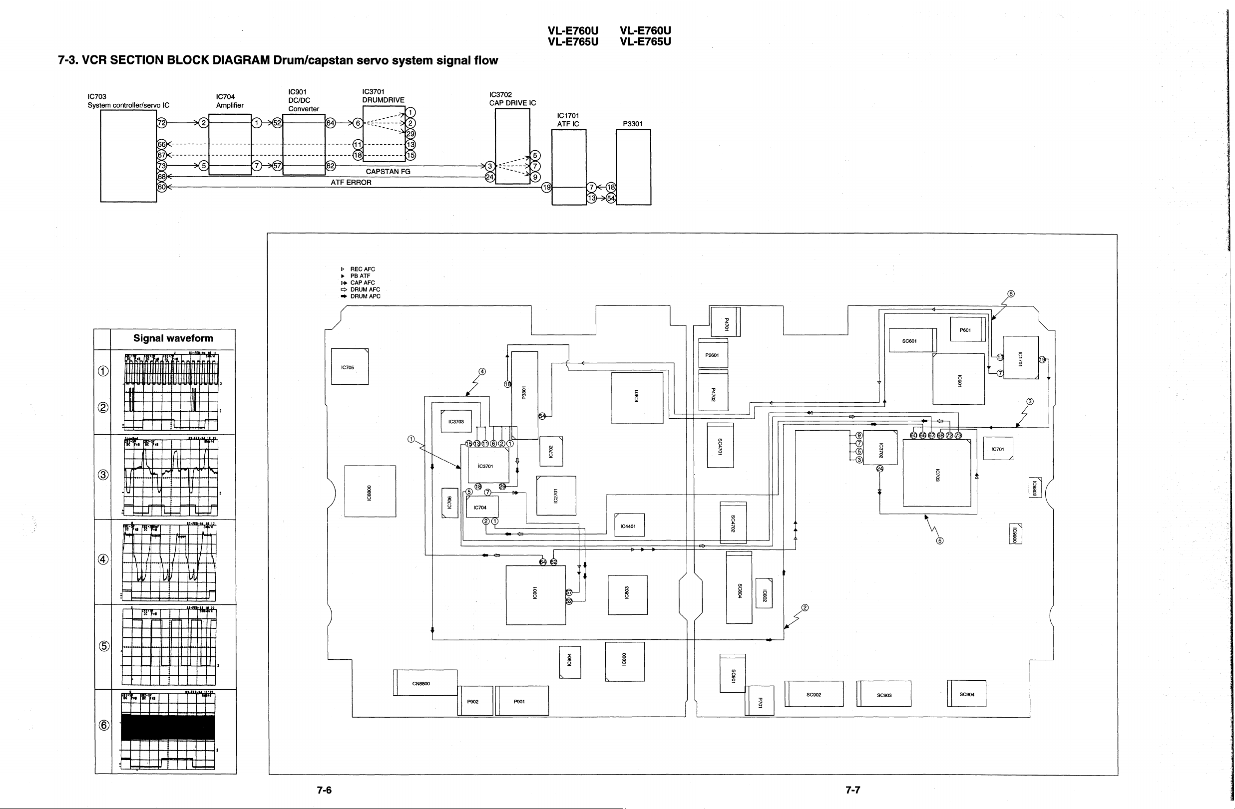
Page 64

Page 65

Page 66

Page 67

Page 68

Page 69

Page 70

Page 71

Page 72

Page 73

Page 74

Page 75

Page 76
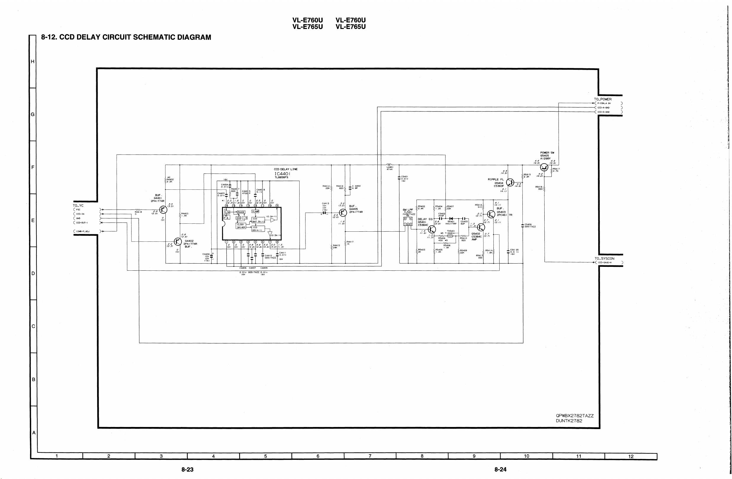
Page 77

Page 78

Page 79

Page 80

Page 81

Page 82

Page 83

Page 84

Page 85

Page 86

Page 87

Page 88

Page 89

Page 90

Page 91

11. REPLACEMENT PARTS LIST/ EXPLODED VIEWS
ELECTRICAL PARTS LIST
Parts marked with “A’ are important for maintaining the safety of the
set. Be sure to replace these parts with specified ones for maintaining
the safety and performance of the set.
Les pieces marquess “/r\‘sont importantes pour maintenir la securite
de I’appareil. Ne remplacer ces pieces que par des pieces dont le
numero est specific pour maintenir la securite et proteger le bon
fonctinnement de I’appareil.
fl HOW TO ORDER REPLACEMENT PARTS u
in USA:
in CANADA:
Contact your nearest SHARP Parts Distributor. For
location of SHARP Parts Distributor,
Call Toll-free 1 -IBE800-SHARP
Contact SHARP Electronics of Canada Limited
Phone (416) 890-2100.
Ref. No.
IC904
IC705
IC706
IC800
IC801
IC802
IC803
IC901
IC902
IC1701
IC2701
IC3701
lC3702
lC3703
IC4401
Part No. * Description
VHiNJM2904M-1
RH-iX0478TAZZ
VHiRS5C313/-1
VHiiR3Y29AM-1
VHiNJM2107F-1
VHiNJM4565V-1
VHiLZ95NAl/-1
RH-iX0325TAZZ
VHiTA75SOl F-l
VHiCXAl814N-1
VHiMB88344F-1
VHiLB195OV/-1
VHiLB1951V/-1
VHiLB1638M/-1
VHiTL8856FS1
NJM2904M
IX0478TA-E2
RS5C313-E2
IR3Y29AM
NJM2107F
NJM4565V
LZ95NAl
MB4484PFV-G
TA75SOl F
CXA1814N/-T4
MB88344PFV
LB1 950V-TRM
LB1 951 V-TRM
LB1 638M-TE-R
TL8856FS(EL)
VL-E760U
VL-E765U
Code
AE
AR
AL
AV
AE
AF
AR
AY
AD
AQ
AV
AQ
AN
AK
AH
*MARK :
To have your order filled promptly and correctly, please furnish
the following informations.
L’ASSEMBLANGE P.C.I. EST UN ARTICLE NON REMPLACABLE
Ref. No. Part No. * Description
S
PARE PARTS-DELIVERY SECTION:ALL JAPAN
1. MODEL NUMBER
3. PART NO.
5. PRICE CODE
A MARK: SAFETY RELATED PARTS
A PIECES: RELATIVES A LA SECURITE
PWB ASSEMBLY IS NOT REPLACEMENT ITEM
2. REF. NO.
4. DESCRIPTION
PRINTED WIRING BOARD ASSEMBLIES
(NOT REPLACEWENT ITEM)
DUNTK2782QA03 VCR Unit(VL-E760U) DUNTK2782QA04 VCR Unit(VL-E765U) DUNTK2785PMOl CAMERA Unit(VL-E760U) DUNTK2785PM02 CAMERA Unit(VL-E765U) DUNTK2800PMOO CCD Unit
RAMP-001 7TAN0 Head Amp Unit
DUNTK2782QA03 VCR UNIT(VL-E760U)
DUNTK2782QA04 VCR UNIT(VL-E765U)
INTEGRATED CIRCUITS
A CP901 VHiCCP2E50/-1 I.C.
A CP902 VHiCCP2E50/-1 I.C.
IC401
IC601
IC701
IC702 VHiXL93L56F-1 XL93LC56F
IC703 RH-iX0591TAZZ
IC704 VHiNJM2904M-1 NJM2904M
VHiAN2492F/-1 AN2492FH
VHiLA7458W/-1
VHiRM3329B/-1
LA7458W
RS5RM3329B-T2
CXP87460-122R
Code
AD
AD
AX
AT
AL
AK
AY
AE
Q401
Q402
Q403
Q404
Q405
Q406
Q407
Q409
Q411
Q412
Q414
Q601
Q602
Q603
Q701
Q702
Q703
Q704
Q714
Q715
Q721
Q800
Q803
Q804
Q901
Q903
Q905
Q907
Q908
Q909
Q910
TRANSISTORS
VSRTl N241 U/-l
VSRTI N241 U/-l
VSUMD2/////-1
VSUMD2/////-1
VSRTI P241 U/-l
VS2PAl774R/-1
VS2SC5383Fk1
VSRTI N241 U/-l
VS2SC5384C/-1
VSRTI P241 U/-l
VSRTI N441 U/-l
VS2SAl298Ykl
VSDTC144EE/-1
VS2SC4738Y/-1
VS2SB12956/-1
VSDTC144EE/-1
VSXP6501///-1
VSUMD2/////-1
VSUMT2/////-1
VSUPUMZl///-1
VS2SAl774F/-1
VSU MA2/////- 1
VSUPUMZl///-1
VSUMG2/////-1
VSFP301 /l/l-l
VS2SB12956/-1
VSFZT1048A/-1
VS2SAl973//-1
VS2SAl973k1
VS2SAl973//-1
VS2SAl973//-1
Transistor
Transistor
Transistor
Transistor
Transistor
Transistor
Transistor
Transistor
Transistor
Transistor
Transistor
Transistor
Transistor
Transistor
Transistor
Transistor
Transistor
Transistor
Transistor
Transistor
Transistor
Transistor
Transistor
Transistor
Transistor
Transistor
Transistor
Transistor
Transistor
Transistor
Transistor
AB
AB
AC
AC
AB
AB
AB
AB
AB
A0
AB
AB
AA
AA
AB
AA
AB
AC
AB
AC
AA
AB
AC
AC
AD
AB
AF
AD
AD
AD
AD
11-l
Page 92

VL-E760U
VL-E765U
Ref. No.
Part No.
* Description
Ref. No.
Part No. * Description
Code
Q911
Q912
Q913
Q914
Q915
Q916
Q917
Q918
Q919
Q920
Q923
Q925
Q926
Q927
Q928
Q929
Q933
Q934
Q937
Q1402
Q1403
Q1404
Q3701
Q3702
Q4401
Q4402
Q4405
Q5401
Q5402
Q5403
Q5404
Q5405
Q7402
Q7403
Q7404
Q7405
Q8402
Q8403
Q8404
Q8405
Q8407
Q8408
Q8409
Q9401
D401
D601
VSU MA4/////- 1
VSMPLl/l/ll-1
VS2SB1123//-1
VSUMD2/////-1
VSUMD2/////-1
VSUMH2/////-1
VSUMD2/////-1
VSUMD2/////-1
VSUMD2/////-1
VSUMG2/////-1
VSUMD2/////-1
VS FX803////- 1
VSMPLI /////-I
VSMPLI ///l/-l
VSFZTI 048A/-1
VS2SAl774F/-1
VSUMD2/////-1
VS2SAl774F/-1
VSDTA144EE/-1
VS2SAl989R/-1
VS2SC5383F/-1
VSXPl B301//-1
VSUPUMXl///-1
VSUMB2/////-1
VS2PAI 774R/-1
VS2PAl774R/-1
VS2PAl774Rbl
VS2SC5384C/-1
VS2SC5384C/-1
VS2PC4617Rbl
VS2SC5383F/-1
VS2SAl298Yb1
VS2SAl989R/-1
VS2SC5384C/-1
VS2SAl989R/-1
VSRTI P241 U/-l
VSUPUMXl///-1
VSRTI N141 U/-l
VSUPUMZl///-1
VSUPUMXl///-1
VS2SC5383F/-1
VS2SC5383F/-1
VS2SAl989R/-1
VSUPUMXl///-1
Transistor
Transistor
Transistor
Transistor
Transistor
Transistor
Transistor
Transistor
Transistor
Transistor
Transistor
Transistor
Transistor
Transistor
Transistor
Transistor
Transistor
Transistor
Transistor
Transistor
Transistor
Transistor
Transistor
Transistor
Transistor
Transistor
Transistor
Transistor
Transistor
Transistor
Transistor
Transistor
Transistor
Transistor
Transistor
Transistor
Transistor
Transistor
Transistor
Transistor
Transistor
Transistor
Transistor
Transistor
DIODES AND LED’S
VHDMAI 33///-l Diode
VHDMAI 32K//-1 Diode
AB
AE
AC
AC
AC
AC
AC
AC
AC
AC
AC
AG
AE
AE
AF
AA
AC
AA
AA
AB
AB
AD
AC
AB
AB
AB
AB
AB
AB
AB
AB
AB
AB
AB
AB
AB
AC
AB
AC
AC
AB
AB
AB
AC
AB
AA
D701
D702
0802
0803
D805
D901
D902
D903
D904
D905
D906
Di 901
D5401
RH-DXOI 82TAZZ
RH-DXOI 82TAZZ
VHDMAI 32K//-1
VHDHVC359TR-1
RH-EXO189TAZZ
VHDFI J2H///-1
RH-EXOI 93TAZZ
VHDI SS355//-1
VHDDA227///-1
VHDFOI J2E//-1
VHDFI J2H///-1
VHDMA2Sll l/-l
VHDHVU17TRF-1
Diode
Diode
Diode
Diode
Zener Diode
Diode
Zener Diode
Diode
Diode
Diode
Diode
Diode
Diode
PACKAGED CIRCUITS
TH800 VHHTI 103K44-1 Thermistor
TH5401 VHHTI 222K41-1
x401
x701
X702
X800 RCRSC0087TAZZ
RCRSCOI 1 STAZZ Crystal
RCRSC0030TAZZ Crystal
RCRSC0032TAZZ Crystal
Thermistor
Crystal
COIL AND TRANSFORMERS
FL701 RCiLB0039TAZZ
FL5401 RCiLF0367TAZZ
L401
L402
L403
L404
L601
L602
L603
L701
L702
L703
L800
L802
L803
L804
L805
L901
L902
L903
L904
L905
L906
L907
L908
VPAXM220KR88N
VPAWMlOlJ140N
VPAEM151J110N
VPAEM220J2R9N
VPAXMl 01 K4RON
VPAXMI 01 K4RON
VP-WM220KR71 N
RCiLP0241 TAZZ
VPAXM220KR88N
VPAXM220KR88N
VPAWM470J6R4N
VPAXM470Kl R7N
VPAXMI OOKR42N
VPAWMI R2JR78N
VPAEM120Jl R9N
RCiLP0226TAZZ
RCiLP0206TAZZ
VPAXMI 01 K4RON
VPAXMI OOKR42N
RCiLPOl GOTAZZ
RCiLP0206TAZZ
VPAXMI OOKR42N
VPAXM2R2MR16N
Oscillation Coil
Coil
Peaking 22p.H 10%
Peaking 100pH 5%
Peaking 150pH 5%
Peaking 22pH 5%
Peaking IOOpH 10%
Peaking IOOpH 10%
Peaking 22pH 10%
Coil
Peaking 22pH 10%
Peaking 22pH 10%
Peaking 47pH 5%
Peaking 47pH 10%
Peaking IOpH 10%
Peaking 1.2pH 5%
Peaking 12pH 5%
Coil
Coil
Peaking IOOpH 10%
Peaking 10pH 10%
Coil
Coil
Peaking IOpH 10%
Peaking 2.2pH 20%
AD
AD
AA
AD
AC
AD
AC
AB
AB
AC
AD
AC
AE
AD
AD
AH
AG
AG
AK
AE
AH
AC
AC
AC
AC
AC
AC
AB
AF
AC
AC
AC
AC
AC
AD
AC
AE
AE
AC
AC
AE
AE
AC
AC
11-2
Page 93

Ref. No. Part No. * Description
Code
Ref. No. Part No. * Description
VL-E760U
VL-E765U
Code
L909
L910 VPAXM2R2MR16N Peaking 2.2pH 20%
L911 RCiLPOl GOTAZZ Coil
L912 RCiLP0206TAZZ Coil
L913
L914 RCiLP0226TAZZ Coil
L915
L916 VPBAMI OOKR26N Peaking IOpH 10%
L917 VPBAM2R2M090N Peaking 2.2pH 20%
L918 VPBAMl OOKR26N
L919 RCiLPOl GOTAZZ Coil
L920 RCiLP0206TAZZ Coil
L921 VPAXM2R2MR16N
L922 VPAXMI OOKR42N Peaking IOpH 10%
L923 RCiLPOl GOTAZZ
L924 RCiLP0205TAZZ Coil
VPAXMl OOKR42N Peaking IOpH 10%
VPAXMl OOKR42N Peaking IOpH 10%
VPBAMI OOKR26N Peaking 1OpH 10%
Peaking IOpH 10%
Peaking 2.2pH 20%
Coil
\ L925 RCiLP0205TAZZ Coil
L926
L927 RCiLP0223TAZZ Coil
L931
L932 RCiLP0226TAZZ Coil
L1701 VPAXM220KR88N
L2701
L3701 VPAXM2R2MR16N Peaking 2.2pH 20%
L4401 VPAXM470Kl R7N Peaking 47pH 10%
L7402
L7403 VPAEM391 J220N Peaking 390pH 5%
L7404
L7405 VPAEM471 J250N Peaking 470pH 5%
L8401 VPAWMGR8J2Rl N Peaking 6.8pH 5%
L8402 VPAWMI OOJ2R6N Peaking IOpH 5%
L8403 VPAWM8R2J2R3N
L8404
L8405 VPAEM471 J250N Peaking 470pH 5%
L8407 VPAEM331 J21 ON Peaking 330pH 5%
L8408
8, T901 RTRNZOI 28TAZZ Transformer
C402
c403
c404
c405
C406
c407
C408
c409
c410
RCiLP0206TAZZ Coil
VPAXMI 01 K4RON Peaking 100pH 10%
Peaking 22pH 10%
VPAXM220KR88N
VPAEM121 J9RON Peaking 120pH 5%
VPAWMI R8JR98N Peaking 1.8pH 5%
VPAEM121 J9RON
VPAEM471 J250N
Peaking 22pH 10%
Peaking 8.2pH 5%
Peaking 120pH 5%
Peaking 470pH 5%
CAPACITORS
VCKYCZI CBI 03K 0.01 16V Ceramic
VCKYCZI CBI 03K 0.01 16V Ceramic
RGKZ0051 TAZZ Capacitor
VCSATAI AJI 06M
VCSATAlAJ335M 3.3 1 OV Tantalum
VCKYCZI HFI 032 0.01 50V Ceramic
VCSATAlAJ475M 4.7 1 OV Tantalum
VCSATAI AJ475M 4.7
RC-KZ0051 TAZZ Capacitor
IO
1 OV Tantalum
1 OV Tantalum
AC
AC
AE
AE
AC
AE
AC
AC
AC
AC
AE
AE
AC
AC
AE
AE
AE
AE
AE
AC
AE
AC
AC
AC
AC
AC
AC
AC
AC
AC
AC
AD
AC
AC
AC
AC
AH
AB
AB
AC
AC
AC
AB
AC
AC
AC
c411
c412
c413
c414
c415
C416
c417
C418
c419
C420
C421
C423
C424
C425
C426
C427
C428
c429
c430
c431
C432
c433
c435
C436
c437
C438
c439
c440
c441
C442
c443
c445
C446
c447
C448
c449
c450
c451
c453
c454
c455 VCKYTVI CB474K
c457
C458 VCKYCYI HB103K
c459 VCKYCZI CBI 03K
C601
C602 VCKYTVI CF225Z
C603
C604 VCSATJ 1 AJ476M
RC-KZO051 TAZZ
RC-KZ0055TAZZ
RC-KZ0055TAZZ
VCKYTVI CB224K
VCSATAI AJI 06M
VCSATAI AJ475M
VCSATAI AJ 106M
VCSATAI AJ335M
VCKYCZI CBI 03K
VCCCCYlHH151J
RC-KZ0051 TAZZ
VCKYCY 1 HB682K
VCCCCYI HH331 J
VCCCCYI HH391 J
VCCCCZI HH270J
VCKYCZI CBI 03K
VCSATAI AJI 06M
VCKYCZI HF103Z
VCKYCZl CB103K
VCCCCZI HH390J
VCKYCZI CBI 03K
VCKYCZI HFI 032
VCKYCZI CB103K
VCKYCZI CB103K
VCCCCYI HH471 J
RC-KZ0055TAZZ
VCCCCYI HH391 J
VCKYCZI CBI 03K
VCKYCZI CBI 03K
VCCCCZI HH470J
VCCCCZI HH470J
VCKYCZI CB103K
RC-KZO051 TAZZ
VCSATAI AJ 106M
VCKYCZI CB103K
VCSATJ 1 AJ476M
VCCCCYI HH820J
VCSAPDI CJI 05M
VCCCCYlHH150J
VCKYCZI CBI 03K
RC-KZ0051 TAZZ
VCSATAI CJ225M
VCSATJI AJ476M
Capacitor
Capacitor
Capacitor
0.22 l6V
10 1ov
4.7 IOV
10 IOV
3.3 IOV
0.01 16V
150p 5ov
Capacitor
68OOp 5ov
330p 5ov
390p 5ov
5ov
27P
0.01 16V
10 1ov
0.01 5ov
0.01 l6V
5ov
39P
0.01 16V
0.01 5ov
0.01 16V
0.01 16V
470p 5ov
Capacitor
390p 5ov
0.01 16V
0.01 16V
5ov
47P
5ov
47P
0.01 16V
Capacitor
IO IOV
0.01 16V
47 IOV
5ov
82P
1 .o 16V
5ov
15P
0.01 16V
0.47 16V
Capacitor
0.01 5ov
0.01 16V
16V
2.2
16V
2.2
IOV
47
47 IOV
Ceramic
Tantalum
Tantalum
Tantalum
Tantalum
Ceramic
Ceramic
Ceramic
Ceramic
Ceramic
Ceramic
Ceramic
Tantalum
Ceramic
Ceramic
Ceramic
Ceramic
Ceramic
Ceramic
Ceramic
Ceramic
Ceramic
Ceramic
Ceramic
Ceramic
Ceramic
Ceramic
Tantalum
Ceramic
Tantalum
Ceramic
Tantalum
Ceramic
Ceramic
Ceramic
Ceramic
Ceramic
Tantalum
Ceramic
Tantalum
Tantalum
AC
AD
AD
AB
AC
AC
AC
AC
AB
AA
AC
AA
AA
AA
AB
AB
AC
AB
AB
AB
AB
AB
AB
AB
AA
AD
AA
AB
AB
AB
AB
AB
AC
AC
AB
AE
AA
AC
AA
AB
AC
AC
AA
AB
AC
AC
AE
AE
11-3
Page 94

VL-E760U
,
VL-E765U
Ref. No.
Part No. * Description
Ref. No.
Part No. * Description Code
C605
C606
C607
C608
C609
C610
C611
C612
C613
C614
C615
C616
C617
C618
C619
C620
C621
C622
C623
C624
C625
C626
C627
C628
C629
C630
C631
C632
C633
C634
C635
C636
c637
C638
c701
, C702
c703
c704
c705
C706
c707
C708
c709
c710
c711
C712
c713
c714
VCKYCYI HB103K
VCKYCYl HBI 03K
VCKYCYI HBI 03K
VCKYCYI HB103K
VCKYCYI CF334Z
VCKYCYI HB103K
VCSATEOJJ226M
VCEAPHI HW474M
VCKYCYI HBI 03K
VCKYTVI HB223K
VCEAPHlHW105M
VCKYCYI HBI 02K
VCSATEl AJ336M
RC-KZOO51 TAZZ
VCSATEI DJ475M
VCKYCY 1 HBI 03K
VCSATEI DJ475M
VCSAPDl DJ474M
VCSATEI CJI 06M
VCEAPFOJW476M
VCSATEI DJ475M
VCKYCYI HBI 03K
VCKYCYI HBI 03K
VCKYCYI HB682K
VCKYCYI HB332K
VCKYCYI HBI 03K
VCSATAI EJI 05M
VCKYCYI HB222K
VCKYCYI CBI 04K
VCKYCYl CBI 04K
VCKYCYI HBI 03K
VCSATAI EJIOSM
VCSATJ 1 AJ476M
VCKYCYI CBI 04K
VCKYCYI HB102K
VCKYCYl HB102K
VCKYCYI HB102K
VCKYCYl HB102K
VCKYCY 1 HB102K
VCKYCYI HB102K
VCEAPFI AW476M
VCSATJI CJ226M
VCSATAI AJ475M
VCEAPFOJWI 07M
VCKYCYI CFI 042
VCKYCYI CFI 042
VCKYCYI CBI 04K
VCKYCYI CF104Z
0.01 50V Ceramic
0.01 50V Ceramic
0.01 50V Ceramic
0.01 50V Ceramic
0.33 16V Ceramic
0.01 50V Ceramic
22 6.3V Tantalum
0.47 50V Electrolytic
0.01 50V Ceramic
0.022 50V Ceramic
1.0 50V Electrolytic
IOOOp 50V Ceramic
33 1 OV Tantalum
Capacitor
4.7 20V Tantalum
0.01 50V Ceramic
4.7 20V Tantalum
0.47 20V Tantalum
10 16V Tantalum
47 6.3V Electrolytic
4.7 20V Tantalum
0.01 50V Ceramic
0.01 50V Ceramic
6800~ 50V Ceramic
3300~ 50V Ceramic
0.01 50V Ceramic
1.0 25V Tantalum
2200~ 50V Ceramic
0.1 16V Ceramic
0.1 16V Ceramic
0.01 50V Ceramic
1 .o 25V Tantalum
47 1 OV Tantalum
0.1 16V Ceramic
IOOOp 50V Ceramic
IOOOp 50V Ceramic
IOOOp 50V Ceramic
IOOOp 50V Ceramic
IOOOp 50V Ceramic
IOOOp 50V Ceramic
47 1 OV Electrolytic
22 16V Tantalum
4.7 1 OV Tantalum
100 6.3V Electrolytic
0.1 16V Ceramic
0.1 16V Ceramic
0.1 16V Ceramic
0.1 16V Ceramic
AA
AA
AA
AA
AA
AA
AD
AB
AA
AB
AB
AA
AG
AC
AD
AA
AD
AD
AD
AB
AD
AA
AA
AA
AA
AA
AC
AA
AB
AB
AA
AC
AE
AB
AA
AA
AA
AA
AA
AA
AB
AE
AC
AC
AA
AA
AB
AA
c715
C716
c717
c719
C720
C721
C722
C723
C724
C725
C726
C727
C728
c729
c730
c731
C732
c733
c734
C801
C803
C804
C805
C806
C807
C808
C809
C810
C811
C812
C813
C814
C815
C816
C817
C818
C819
C820
C821
C822
C823
C824
C830
C831
C832
C836
C837
VCKYCYI CBI 04K
VCCCCYiHH180J
VCKYCYI HB471 K
VCCCCY 1 HH 180J
VCKYCYI EB103K
VCKYCYI HBI 02K
VCKYCYl HBI 02K
VCKYCYl HBI 02K
VCKYCY 1 CBI 04K
VCKYCYI HB682K
VCKYCYI HBI 02K
VCKYCYI CFI 042
VCKYCYI CBI 04K
VCKYCY 1 EBl03K
VCKYCY 1 AFI 052
VCEAPHl EW475M
VCKYCYI CFI 042
VCKYCY 1 CBl04K
VCCCCYI HH200J
VCKYCYI CB104K
VCKYCZI HB471 K
RC-KZ0051 TAZZ
VCKYCZI HFI 032
VCKYCZI HFI 032
VCKYCZI HFI 032
VCKYCZI HFI 032
VCKYCZI HFI 032
VCKYCZI HFlO3Z
VCKYTVI CFI 05Z
VCKYCZl HFI 032
VCKYCZI HFI 032
VCKYTVI CFI 052
VCKYCZI HFI 032
VCKYTVI CFI 052
VCKYCZI HFI 032
VCKYCZI HFI 032
VCKYCZI HFI 032
VCCCCZI HHI 50J
VCCCCZI HH560J
VCKYTVI CFI 052
VCKYTVI CB474K
VCSATAI AJ335M
VCKYCZI HFI 032
VCSATJl CJ226M
VCSATAI AJ 106M
VCKYCZI HFI 032
VCKYCZI HF103Z
VCCCCZI HH270J
0.1 16V
5ov
16P
470p 5ov
5ov
16P
0.01 25V
IOOOp 5ov
IOOOp 5ov
IOOOp 5ov
0.1 16V
68OOp 5ov
IOOOp 5ov
0.1 16V
0.1 16V
0.01 25V
1 .o iov
4.7 25V
0.1 l6V
0.1 16V
5ov
20P
0.1 l6V
470p 5ov
Capacitor
0.01 5ov
0.01 5ov
0.01 5ov
0.01 5ov
0.01 5ov
0.01 5ov
1 .o 16V
0.01 5ov
0.01 5ov
1 .o 16V
0.01 5ov
1 .o 16V
0.01 5ov
0.01 5ov
0.01 5ov
5ov
l5P
5ov
56P
1 .o l6V
0.47 16V
3.3 IOV
0.01 5ov
22 l6V
IO IOV
0.01 5ov
0.01 5ov
5ov
27P
Ceramic
Ceramic
Ceramic
Ceramic
Ceramic
Ceramic
Ceramic
Ceramic
Ceramic
Ceramic
Ceramic
Ceramic
Ceramic
Ceramic
Ceramic
Electrolytic
Ceramic
Ceramic
Ceramic
Ceramic
Ceramic
Ceramic
Ceramic
Ceramic
Ceramic
Ceramic
Ceramic
Ceramic
Ceramic
Ceramic
Ceramic
Ceramic
Ceramic
Ceramic
Ceramic
Ceramic
Ceramic
Ceramic
Ceramic
Tantalum
Ceramic
Tantalum
Tantalum
Ceramic
Ceramic
Ceramic
AB
AA
AA
AA
AA
AA
AA
AA
AB
AA
AA
AA
AB
AA
AC
AB
AA
AB
AA
AB
AB
AC
AB
AB
AB
AB
AB
AB
AB
AB
AB
AB
AB
AB
AB
AB
AS
AB
AB
AB
AC
AC
AB
AE
AC
AB
AB
AB
11-4
Page 95

Ref. No. Part No. * Description
Ref. No.
Part No.
VL-E760U
VL-E765U
*
Description Code
C838
C839
C840
C841
C842
C844
C845
C846
C847
C848
C849
C850
C851
C852
C854
I
C856
C857
C860
C861
C864
C866
C872
C874
C876
C877
C878
C879
C880
C881
C883
c900
c902
c903
c904
c905
C906
c907
C908
c909
c910
c911
c912
c913
c914
c915
C916
c917
VCCCCZlHH150J
VCKYCYI CF334Z
VCKYCZI HFI 032
VCKYCZI HFI 032
VCKYCZI HFI 032
VCSATAI AJ106M
VCSATAI AJI 06M
VCKYCYI CFI 042
VCKYCZI HB561 K
RC-KZ0051 TAZZ
VCKYCYl CFI 042
VCCCCZI HH8ROD
VCKYCYI CFI 042
RC-KZ0051 TAZZ
VCKYCZI HFI 032
VCKYCZI HBI 02K
VCKYCYI CFI 042
RCXZ0051 TAZZ
VCCCCZlHH181J
VCKYCYI CFI 042
VCKYCYI CF224Z
VCKYCYI CFI 042
VCCCCZIHHIOIJ
VCSATAI DJ475M
VCKYCZI HF103Z
VCKYCYI CFI 042
VCKYCYI CF104Z
VCKYCZI HF103Z
RC-KZ0051 TAZZ
RC-KZ0051 TAZZ
VCKYCYI CFI 042
VCEAPFlAW476M
RC-KZ0055TAZZ
RC-KZ0055TAZZ
RC-KZ0055TAZZ
RCXZ0049TAZZ
RC-KZ0042TAZZ
RC-KZOO55TAZZ
RC-KZOO55TAZZ
RC-KZ0027TAZZ
RC-KZ0042TAZZ
RC-KZ0055TAZZ
RC-KZ0055TAZZ
RC-KZ0055TAZZ
RC-KZ0049TAZZ
RC-KZOO58TAZZ
RC-KZ0058TAZZ
RC-KZ0048TAZZ
5ov
15P
0.33 16V
5ov
0.01
0.01 5ov
5ov
0.01
10 1ov
10 IOV
16V
0.1
560~ 50V
Capacitor
16V
0.1
8.0~ 50V
16V
0.1
Capacitor
5ov
0.01
IOOOp 5ov
16V
0.1
Capacitor
180~ 50V
0.1 16V
16V
0.22
16V
0.1
loop 5ov
4.7 2ov
0.01 5ov
16V
0.1
l6V
0.1
0.01 5ov
Capacitor
Capacitor
16V
0.1
IOV
47
Capacitor
Capacitor
Capacitor
Capacitor
Capacitor
Capacitor
Capacitor
Capacitor
Capacitor
Capacitor
Capacitor
Capacitor
Capacitor
Capacitor
Capacitor
Capacitor
Ceramic
Ceramic
Ceramic
Ceramic
Ceramic
Tantalum
Tantalum
Ceramic
Ceramic
Ceramic
Ceramic
Ceramic
Ceramic
Ceramic
Ceramic
Ceramic
Ceramic
Ceramic
Ceramic
Ceramic
Tantalum
Ceramic
Ceramic
Ceramic
Ceramic
Ceramic
Electrolytic
AB
AA
AB
AB
AB
AC
AC
AA
AC
AC
AA
AB
AA
AC
AB
AB
AA
AC
AB
AA
AA
AA
AB
AC
AB
AA
AA
AB
AC
AC
AA
AB
AD
AD
AD
AD
AE
AD
AD
AF
AE
AD
AD
AD
AD
AC
AC
AD
C918
c919
c920
c921
c922
c923
c924
c925
C926
c927
C928
c929
c930
c931
c940
c941
c942
c943
c944
c945
Cl 402
Cl403
Cl 404
Cl 405
Cl 701
Cl 702
Cl 703
Cl 704
Cl 705
Cl706
Cl 707
Cl 708
Cl 709
Cl710
Cl711
Cl 901
Cl 902
Cl 903
Cl 904
Cl 906
Cl 907
Cl 908
Cl 909
Cl910
Cl911
Cl912
Cl913
Cl914
RC-KZ0058TAZZ
VCKYTVI EBI 04K
VCKYTVI EB104K
VCKYTQI CBI 05K
VCKYTVI EBI 04K
RC-KZOO42TAZZ
RC-KZ0042TAZZ
VCKYTVI CFI 05Z
VCKYTVI ABI 05K
RC-KZ0042TAZZ
RC-KZO049TAZZ
RC-KZ0042TAZZ
RCXZ0049TAZZ
RC-KZ0049TAZZ
VCKYCZl CB103K
VCKYCYI EFI 042
VCKYTVI CFI 052
RC-CZOOI 7TAZZ
VCKYTVI CFI 052
VCKYCY 1 EBI 03K
RC-KZ0051 TAZZ
RCXZOO42TAZZ
VCKYCZI CBI 03K
VCSATAI AJI 06M
VCSATEI AJ336M
VCKYCYI HF103Z
VCKYCYlHF103Z
VCKYCY 1 CF104Z
VCKYCYI HFI 032
VCKYCYlHF1032
VCKYCYlHF1032
VCKYCY 1 CFI 042
VCKYCYI HFI 032
VCCCCYI HH8ROD
VCKYCYI HB472K
VCKYTVI EBI 04K
VCKYCYI HB332K
VCKYCYI CBI 04K
VCKYCZI HB222K
VCKYCZl CBI 03K
VCKYCYI CB104K
VCKYCZI EB682K
VCKYCYI CBI 04K
VCCCCYlHH181J
VCCCCYlHH181J
VCKYTVI CB474K
VCKYTVI EBI 04K
VCKYTVl EBI 04K
Capacitor
0.1 25V
0.1 25V
1 .o 16V
0.1
25V
Capacitor
Capacitor
1 .o 16V
1 .o IOV
Capacitor
Capacitor
Capacitor
Capacitor
Capacitor
0.01 16V
0.1 25V
1 .o 16V
Capacitor
1 .o 16V
0.01 25V
Capacitor
Capacitor
0.01 16V
IO IOV
33 1ov
0.01 5ov
0.01 5ov
0.1 16V
0.01 5ov
0.01 5ov
0.01 5ov
0.1 16V
0.01 5ov
8.0~ 50V
4700p 5ov
0.1 25V
3300p 5ov
0.1 l6V
2200p 5ov
0.01 16V
0.1 16V
6800~ 25V
0.1
16V
180~ 50V
180~ 50V
0.47 l6V
0.1 25V
0.1 25V
Ceramic
Ceramic
Ceramic
Ceramic
Ceramic
Ceramic
Ceramic
Ceramic
Ceramic
Ceramic
Ceramic
Ceramic
Tantalum
Tantalum
Ceramic
Ceramic
Ceramic
Ceramic
Ceramic
Ceramic
Ceramic
Ceramic
Ceramic
Ceramic
Ceramic
Ceramic
Ceramic
Ceramic
Ceramic
Ceramic
Ceramic
Ceramic
Ceramic
Ceramic
Ceramic
Ceramic
Ceramic
AC
AB
AB
AC
AB
AE
AE
AB
AD
AE
AD
AE
AD
AD
AB
AA
AB
AE
AB
AA
AC
AE
AB
AC
AG
AA
AA
AA
AA
AA
AA
AA
AA
AA
AA
AB
AA
AB
AB
AB
AB
AB
AB
AA
AA
AC
AB
AB
11-5
Page 96

VL-E760U
VL-E765U
Ref. No. Part No.
* Description
Ref. No.
Part No.
* Description
Cl915
Cl916
Cl917
Cl918
Cl919
Cl 920
Cl 921
Cl 922
Cl 923
Cl 924
Cl 925
Cl 926
Cl 927
Cl 928
C2701
C2702
C2703
c3701
C3702
c3703
c3704
c3705
C3706
c3707
C3708
c3709
c3710
c3711
C3712
c3713
c3715
C3716
c3717
C3718
c3719
C3720
C3721
C3722
C3723
C3724
C3725
C4402
c4403
c4404
c4405
C4406
c4407
VCKYTVl EBI 04K
VCKYCY 1 CB333K
VCKYTVI CF225Z
VCKYCYl CBI 04K
VCKYTVI EBI 04K
VCKYCYI CB473K
VCKYCZI HBI 02K
VCKYTVl EBI 04K
VCKYCZI HBI 02K
VCKYTVl EB104K
VCKYCZI HBI 02K
VCKYTVI EBI 04K
VCKYCZI HBI 02K
VCKYTVI EBI 04K
VCKYCYI CFI 042
VCKYCYI CFI 042
VCSATAI AJ475M
VCKYCY 1 CFI 042
VCKYCYI CFI 042
VCKYCYI CF104Z
VCKYCYI EBI 03K
VCKYCYI EB103K
VCKYCYI EBI 03K
VCKYCYlCBl04K
VCKYCYl CFI 042
VCKYCY 1 CB473K
VCKYCY 1 CB473K
VCKYCYI HB472K
VCKYTVI CFI 052
VCKYCYI HB682K
VCKYCYI HB682K
VCKYCY 1 CFI 042
VCSATAI AJI 06M
VCKYCYI CFlO4Z
VCSATAI AJ106M
VCKYCYI CFI 042
VCKYCYI CFI 042
VCKYCYI CFI 042
VCKYTVI CFI 05Z
VCKYCY 1 CFI 042
VCKYCYI CFI 042
VCKYCYI CBl04K
VCSATAlAJ106M
VCKYCZI HF103Z
VCKYCZI CB103K
VCKYCZI EB472K
VCKYCZI CBI 03K
RC-KZ0051 TAZZ
25V Ceramic
0.1
0.033 16V Ceramic
2.2 16V Ceramic
0.1 16V Ceramic
0.1 25V Ceramic
0.047 16V Ceramic
IOOOp 50V Ceramic
0.1 25V Ceramic
1OOOp 50V Ceramic
0.1 25V Ceramic
IOOOp 50V Ceramic
0.1 25V Ceramic
IOOOp 50V Ceramic
0.1 25V Ceramic
0.1 16V Ceramic
0.1 16V Ceramic
4.7 1 OV Tantalum
0.1 16V Ceramic
0.1 16V Ceramic
0.1 16V Ceramic
0.01 25V Ceramic
0.01 25V Ceramic
0.01 25V Ceramic
0.1 16V Ceramic
0.1 16V Ceramic
0.047 16V Ceramic
0.047 16V Ceramic
4700p 50V Ceramic
1 .o 16V Ceramic
6800p 50V Ceramic
6800p 50V Ceramic
0.1 16V Ceramic
IO 1 OV Tantalum
0.1 16V Ceramic
IO 1 OV Tantalum
0.1 16V Ceramic
0.1 16V Ceramic
0.1 l6V Ceramic
1 .o 16V Ceramic
0.1 16V Ceramic
0.1 16V Ceramic
0.1 16V Ceramic
10 1 OV Tantalum
0.01 50V Ceramic
0.01 16V Ceramic
4700~ 25V Ceramic
0.01 16V Ceramic
Capacitor
AB
AA
AC
AB
AB
AA
AB
AB
AB
AB
AB
AB
AB
AB
AA
AA
AC
AA
AA
AA
AA
AA
AA
AB
AA
AA
AA
AA
AB
AA
AA
AA
AC
AA
AC
AA
AA
AA
AB
AA
AA
AB
AC
AB
AB
AB
AB
AC
C4408
c4409
c4410
c4411
c4413
c4453
c5401
C5402
c5403
c5405
C5406
c7401
c7404
c7405
C7406
c7407
c7409
c7410
C8401
C8402
C8403
C8404
C8405
C8406
C8407
C8408
C8412
C8413
C8414
C8415
C8416
c9401
c9402
c9403
c9404
R401
R403
R404
R405
R406
R407
R409
R412
R413
R414
R416
VCKYTVI EBI 04K
VCKYCZl CBI 03K
RC-KZ0051 TAZZ
VCKYCZI CB103K
VCSATAlAJ106M
VCCCCZl HH680J
VCKYCZI CBI 03K
VCCCCYI HH471 J
VCCCCZl HH820J
VCKYCZI CBI 03K
RC-KZ0051 TAZZ
VCCCCY 1 EH561 J
VCCCCZI HH470J
VCCCCZlHHlOlJ
VCCCCZlHH121J
VCCCCZIHHIOIJ
VCCCCZI HHI OOD
VCKYCZI CBI 03K
VCCCCZI HH820J
VCCCCZI HH560J
VCKYCZl HFI 032
VCCCCZI HH15OJ
VCCCCZl HH390J
VCCCCYI HH271 J
VCKYCZI CBI 03K
VCCCCZI HH330J
VCCCCYI HH471 J
VCCCCZI HH330J
VCKYCYI HB222K
VCKYCYI HB222K
RC-KZ0051 TAZZ
VCKYCYI HFI 032
VCKYCZI CBI 03K
VCCCCZI HH220J
VCCCCZI HH220J
0.1 25V Ceramic ’ AB
0.01 16V
Capacitor
0.01 16V
IO IOV
5ov
68P
0.01 16V
470p 5ov
5ov
82P
0.01 16V
Capacitor
560~ 25V
5ov
47P
loop 5ov
120p 5ov
loop 5ov
5ov
1OP
0.01 16V
5ov
82P
5ov
56P
0.01 5ov
5ov
15P
5ov
39P
270~ 50V
0.01 16V
5ov
33P
470p 5ov
5ov
33P
2200p 5ov
2200p 5ov
Capacitor
0.01 5ov
0.01 16V
5ov
22P
5ov
22P
RESISTORS
VRS-CZ1 JF682J 6.8k l/l 6W
VRS-CZI JF682J
VRS-CZI JFOOOJ
VRS-CZI JFI 020
VRS-CZI JF621 D
VRS-CZI JF751 D
VRS-CZI JFI 02J
VRS-CZI JF332J
VRS-CZl JF684J
VRS-CZl JFOOOJ
VRS-CZI JF474J
6.8k l/l 6W
00 1/16W
1 .Ok 1/16W
620 1/16W
750 1/16W
1 .Ok l/l 6W
3.3k i/l 6W
680k l/l 6W
00 1/16W
470k l/l 6W
Ceramic
Ceramic
Tantalum
Ceramic
Ceramic
Ceramic
Ceramic
Ceramic
Ceramic
Ceramic
Ceramic
Ceramic
Ceramic
Ceramic
Ceramic
Ceramic
Ceramic
Ceramic
Ceramic
Ceramic
Ceramic
Ceramic
Ceramic
Ceramic
Ceramic
Ceramic
Ceramic
Ceramic
Ceramic
Ceramic
Ceramic
Metal Oxide AA
Metal Oxide AA
Metal Oxide AA
Metal Oxide AA
Metal Oxide AA
Metal Oxide AB
Metal Oxide AA
Metal Oxide AA
Metal Oxide AA
Metal Oxide AA
Metal Oxide AA
AB
AC
AB
AC
AB
AB
AA
AB
AB
AC
AA
AB
AB
AB
AB
AB
AB
AB
AB
AB
AB
AB
AA
AB
AB
AA
AB
AA
AA
AC
AA
AB
AB
AB
11-6
Page 97

Ref. No. Part No. *
Description Code Ref. No.
VL-E760U
VL-E765U
Part No. * Description Code
R420
R421
R423
R424
R425
R426
R428
R430
R431
R433
R434
R435
R436
R437
R438
R439
R440
R442
R443
R444
R445
R446
R449
R450
R451
R452
R453
R601
R602
R603
R604
R605
R606
R607
R608
R609
R611
R612
R614
R615
R616
R617
R618
R619
R620
R621
R623
R624
VRS-CZI JF471 D
VRS-CZI JF681 J
VRS-CZI JF222J
VRS-CZl JF302J
VRS-CZI JFI 22D
VRS-CZI JF431 D
VRS-CZI JFI 22D
VRS-CZI JFI 22D
VRS-CZI JF201 D
VRS-CZI JF473J
VRS-CZI JF471 J
VRS-CZI JFOOOJ
VRS-CZI .JFlO3J
VRS-CZI JFI 03J
VRS-CZI JFI 03D
VRS-CZI JFOOOJ
VRS-CZI JFI 52D
VRS-CZI JF223D
VRS-CZI JFI 52D
VRS-CZI JFOOOJ
VRS-CZI JFI 05J
VRS-CZl JFI 05J
VRS-CZI JFOOOJ
VRS-CZI JFOOOJ
VRS-CZI JFOOOJ
VRS-CZI JFI 02J
VRS-CZI JFI 02J
VRS-CZI JFI 03J
VRS-CZI JFI 82J
VRS-CZI JFI 54J
VRS-CZI JFI 53J
VRS-CZI JF472J
VRS-CZI JF334J
VRS-CZI JF334J
VRS-CZI JF563J
VRS-CZI JF222J
VRS-CZI JF332J
VRS-CZI JF681 J
VRS-CZI JFI 22J
VRS-CZI JF561 J
VRS-CZI JF333J
VRS-CZI JF335J
VRS-CZI JFI 54J
VRS-CZI JF274J
VRS-CZI JFOOOJ
VRS-CZI JFOOOJ
VRS-CZI JFOOOJ
VRS-CZI JFI 82J
470 lll6W Metal Oxide AA
680 lll6W Metal Oxide AA
2.2k Ill 6W Metal Oxide AA
3.0k 1/16W Metal Oxide A6
1.2k 1/16W Metal Oxide AB
430 1/16W Metal Oxide AA
1.2k l/l 6W Metal Oxide AB
1.2k 1/16W Metal Oxide AB
200 lll6W Metal Oxide AA
47k lll6W
470 1/16W
00 lll6W Metal Oxide AA
IOk 1/16W Metal Oxide AA
IOk 1/16W Metal Oxide AA
IOk 1/16W Metal Oxide AB
00 lll6W
1.5k 1/16W Metal Oxide AB
22k 1/16W Metal Oxide AB
1.5k lll6W Metal Oxide AB
00 1/16W Metal Oxide AA
l.OM lll6W Metal Oxide AA
l.OM 1/16W
00 lll6W Metal Oxide AA
00 1/16W Metal Oxide AA
00 lll6W Metal Oxide AA
1 .Ok 1/16W Metal Oxide AA
l.Ok 1/16W Metal Oxide AA
IOk 1/16W Metal Oxide AA
1.8k 1/16W Metal Oxide AA
150k lll6W Metal Oxide AA
15k 1/16W Metal Oxide AA
4.7k l/l 6W Metal Oxide AA
330k 1 /I 6W Metal Oxide AA
330k l/l 6W
56k 1/16W
2.2k l/l 6W Metal Oxide AA
3.3k 1 /I 6W Metal Oxide AA
680 lll6W Metal Oxide AA
1.2k 1/16W Metal Oxide AA
560 1/16W
33k 1/16W Metal Oxide AA
3.3M 1 /I 6W Metal Oxide AA
150k 1/16W
270k l/l 6W Metal Oxide AA
00 1/16W Metal Oxide AA
00 1/16W Metal Oxide AA
00 1/16W
1.8k lll6W Metal Oxide AA
Metal Oxide AA
Metal Oxide AA
Metal Oxide AA
Metal Oxide AA
Metal Oxide AA
Metal Oxide AA
Metal Oxide AA
Metal Oxide AA
Metal Oxide AA
R625
R626
R627
R628
R629
R632
R633
R699
R702
R703
R704
R705
R706
R707
R708
R709
R710
R711
R712
R714
R715
R716
R718
R719
R720
R721
R722
R723
R724
R725
R726
R727
R728
R730
R731
R732
R733
R734
R736
R737
R738
R739
R740
R741
VRS-CZI JFI 03J
VRS-CZI JFI 22J
VRS-CZI JFI 03J
VRS-CZI JF472J
VRS-CZI JFI 52J
VRS-CZI JF822J
VRS-CZI JF224J
VRS-CZI JFI 04J
VRS-CZI JFI 02J
VRS-CZI JF272J
VRS-CZI JFI 02J
VRS-CZI JFI 02J
VRS-CZI JFI 02J
VRS-CZI JFI 02J
VRS-CZI JFI 02J
VRS-CZI JFI 02J
VRS-CZI JFI 02J
VRS-CZI JFI 02J
VRS-CZI JFI 04J
VRS-CZI JFI 04J
VRS-CZI JFI 04J
VRS-CZI JF224J
VRS-CZI JF224J
VRS-CZI JFI 03J
VRS-CZI JF822J
VRS-CZI JFI 541
VRS-CZI JF334J
VRS-CZI JFI 83J
VRS-CZI JF682J
VRS-CZI JF563D
VRS-CZI JFlO2J
VRS-CZI JFI 03J
VRS-CZI JF334J
VRS-CZI JFI 02J
VRS-CZI JFI 02J
VRS-CZI JFI 54J
VRS-CZI JF823J
VRS-CZI JF333J
VRS-CZI JFI 53J
VRS-CZI JFI 02J
VRS-CZI JFI 02J
VRS-CZI JFI 02J
VRS-CZI JFI 02J
VRS-CZI JFI 02J
VRS-CZI JFI 02J
VRS-CZI JF822J
VRS-CZI JFI 02J
VRS-CZI JFI 04J
IOk 1/16W
1.2k 1/16W
IOk 1/16W
4.7k lll6W
1.5k 1/16W
8.2k 1/16W
220k l/l 6W
IOOk 1/16W
l.Ok 1/16W
2.7k Ill 6W
1 .Ok l/l 6W
l.Ok 1/16W
1 .Ok 1/16W
1 .Ok 1/16W
l.Ok 1/16W
l.Ok 1/16W
l.Ok 1/16W
1 .Ok 1/16W
IOOk 1/16W
IOOk 1/16W
IOOk 1/16W
220k 1/16W
220k l/l 6W
IOk 1/16W
8.2k l/l 6W
150k 1/16W
330k l/l 6W
18k 1/16W
6.8k Ill 6W
56k 1/16W
1 .Ok 1/16W
IOk 1/16W
330k 1 /I 6W
l.Ok 1/16W
1 .Ok l/l 6W
150k 1/16W
82k 1/16W
33k 1/16W
15k 1/16W
1 .Ok 1/16W
1 .Ok l/l 6W
1 .Ok 1/16W
1 .Ok l/l 6W
l.Ok 1/16W
1 .Ok l/l 6W
8.2k l/l 6W
l.Ok 1/16W
IOOk 1/16W
Metal Oxide AA
Metal Oxide AA
Metal Oxide AA
Metal Oxide AA
Metal Oxide AA
Metal Oxide AA
Metal Oxide AA
Metal Oxide AA
Metal Oxide AA
Metal Oxide AA
Metal Oxide AA
Metal Oxide AA
Metal Oxide AA
Metal Oxide AA
Metal Oxide AA
Metal Oxide AA
Metal Oxide AA
Metal Oxide AA
Metal Oxide AA
Metal Oxide AA
Metal Oxide AA
Metal Oxide AA
Metal Oxide AA
Metal Oxide AA
Metal Oxide AA
Metal Oxide AA
Metal Oxide AA
Metal Oxide AA
Metal Oxide AA
Metal Oxide AA
Metal Oxide AA
Metal Oxide AA
Metal Oxide AA
Metal Oxide AA
Metal Oxide AA
Metal Oxide AA
Metal Oxide AA
Metal Oxide AA
Metal Oxide AA
Metal Oxide AA
Metal Oxide AA
Metal Oxide AA
Metal Oxide AA
Metal Oxide AA
Metal Oxide AA
Metal Oxide AA
Metal Oxide AA
Metal Oxide AA
II-7
Page 98

VL-E760U
‘VL-E765U
Ref. No.
Part No. * Description
Code Ref. No.
Part No. *
Description Code
R743
R744
R745
R746
R750
R751
R752
R753
R754
R755
R756
R757
R758
R759
R760
R761
R762
R763
R764
R765
R766
R767
R768
R769
R770
R771
R772
R773
R774
R775
R776
R777
R778
R780
R782
R783
R784
R785
R786
R787
R788
R789
R800
R801
R802
R805
R809
R810
VRS-CZI JFI 04J
VRS-CZI JFI 04J
VRS-CZl JFI 54J
VRS-CZI JFI 04J
VRS-CZI JFI 04J
VRS-CZl JFI 04J
VRS-CZl JF104J
VRS-CZI JF104J
VRS-CZI JFI 04J
VRS-CZI JFI 04J
VRS-CZI JF104-J
VRS-CZI JFI 02J
VRS-CZI JFI 02J
VRS-CZI JFI 02J
VRS-CZl JF823J
VRS-CZl JFI 02J
VRS-CZI JFI 22J
VRS-CZIJFI 03J
VRS-CZI JFI 03J
VRS-CZI JFI 04-J
VRS-CZI JFI 04J
VRS-CZI JFI 04J
VRS-CZI JFlO3J
VRS-CZI JFI 03J
VRS-CZI JFI 02J
VRS-CZI JF224J
VRS-CZI JF104J
VRS-CZI JFI 04J
VRS-CZI JF334J
VRS-CZI JFI 04J
VRS-CZI JF473J
VRS-CZI JF334J
VRS-CZI JFI 03J
VRS-CZI JFI 52J
VRS-CZI JFI 52J
VRS-CZI JF271 J
VRS-CZI JFI 02J
VRS-CZI JFI 02J
VRS-CZl JFI 52J
VRS-CZI JF271 J
VRS-CZI JFI 52J
VRS-CZI JF271 J
VRS-CZI JFI 02J
VRS-CZI JF823J
VRS-CZI JF823J
VRS-CZI JF304D
VRS-CZI JF363D
VRS-CZI JF563D
lOOk’1/16W Metal Oxide AA
IOOk 1/16W Metal Oxide AA
150k 1/16W Metal Oxide AA
IOOk 1/16W Metal Oxide AA
100k 1/16W Metal Oxide AA
IOOk 1/16W Metal Oxide AA
100k 1/16W Metal Oxide AA
1OOk 1/16W Metal Oxide AA
IOOk 1/16W Metal Oxide AA
IOOk 1/16W Metal Oxide AA
IOOk 1/16W Metal Oxide AA
1 .Ok l/l 6W Metal Oxide AA
1 .Ok l/l 6W Metal Oxide AA
1 .Ok l/l 6W
82k 1/16W
1 .Ok 1/16W Metal Oxide AA
1.2k l/l 6W Metal Oxide AA
10k 1/16W
IOk 1/16W Metal Oxide AA
IOOk 1/16W Metal Oxide AA
IOOk 1/16W Metal Oxide AA
IOOk 1/16W Metal Oxide AA
10k 1/16W Metal Oxide AA
10k 1/16W Metal Oxide AA
l.Ok 1/16W Metal Oxide AA
220k 1 /I 6W Metal Oxide AA
100k 1/16W
IOOk 1/16W Metal Oxide AA
330k 1 /I 6W Metal Oxide AA
IOOk 1/16W Metal Oxide AA
47k 1/16W
330k 1/16W Metal Oxide AA
10k 1/16W Metal Oxide AA
1.5k 1/16W Metal Oxide AA
1.5k 1/16W Metal Oxide AA
270 1/16W Metal Oxide AA
1 .Ok 1/16W Metal Oxide AA
1 .Ok l/l 6W Metal Oxide AA
1.5k 1/16W Metal Oxide AA
270 1/16W Metal Oxide AA
1.5k 1/16W Metal Oxide AA
270 1/16W Metal Oxide AA
l.Ok 1/16W
82k l/l 6W
82k 1/16W Metal Oxide AA
300k 1/16W Metal Oxide AA
36k 1/16W
56k 1/16W Metal Oxide AA
Metal Oxide AA
Metal Oxide AA
Metal Oxide AA
Metal Oxide AA
Metal Oxide AA
Metal Oxide AA
Metal Oxide AA
Metal Oxide AA
R811
R812
R815
R816
R817
R818
R819
R820
R821
R825
R826
R828
R829
R831
R832
R833
R835
R836
R837
R838
R839
R841
R842
R847
R849
R850
R851
R853
R854
R855
R858
R859
R860
R861
R862
R865
R866
R867
R868
R869
R870
R871
R872
R873
R874
R876
R877
R878
VRS-CZI JF473D
VRS-CZI JF393D
VRS-CZI JFI 02J
VRS-CZl JFI 02J
VRS-CZI JFI 02J
VRS-CZI JF303D
VRS-CZI JF203D
VRS-CZl JF333D
VRS-CZI JF273D
VRS-CZI JFI 05J
VRS-CZI JFl24F
VRS-CZI JF223D
VRS-CZI JFI 63D
VRS-CZI JFOOOJ
VRS-CZI JF152D
VRS-CZI JFI 830
VRS-CZl JF272J
VRS-CZI JF562J
VRS-CZI JF822J
VRS-CZI JF334J
VRS-CZI JF334J
VRS-CZI JF393D
VRS-CZl JF393D
VRS-CZI JFI 05J
VRS-CZI JF473D
VRS-CZI JFOOOJ
VRS-CZI JF393D
VRS-CZI JFOOOJ
VRS-CZI JF563J
VRS-CZI JFI 04J
VRS-CZI JF223D
VRS-CZl JF273D
VRS-CZI JF223D
VRS-CZI JF223D
VRS-CZI JF563J
VRS-CZl JFI 030
VRS-CZI JF393J
VRS-CZI JF223J
VRS-CZI JF473J
VRS-CZl JF472J
VRS-CZI JF472J
VRS-CZI JF683J
VRS-CZI JFI 05J
VRS-CZl JF683J
VRS-CZI JF473D
VRS-CZI JFI 03J
VRS-CZI JF223J
VRS-CZI JFI 04J
l/l 6W Metal Oxide AB
47k
39k 1/16W
1 .Ok l/l 6W Metal Oxide AA
1 .Ok l/l 6W Metal Oxide AA
1 .Ok 1/16W Metal Oxide AA
30k l/l 6W Metal Oxide AA
20k 1/16W Metal Oxide AA
33k 1/16W
27k 1/16W Metal Oxide AA
l.OM 1/16W Metal Oxide AA
120k 1/16W
22k 1/16W
16k 1/16W
00 1/16W
1.5k lfl6W
18k 1/16W
2.7k l/l 6W
5.6k l/l 6W
8.2k 1/16W
330k l/l 6W
330k l/l 6W
39k 1/16W
39k l/l 6W
1 .OM l/l 6W Metal Oxide AA
47k 1/16W
00 1/16W
39k 1/16W
00 1/16W
56k 1/16W
IOOk 1/16W
22k 1/16W
27k 1/16W
22k l/l 6W Metal Oxide AB
22k 1/16W Metal Oxide AB
56k
1 Ok l/l 6W Metal Oxide AB
39k i/l 6W Metal Oxide AA
22k 1/16W Metal Oxide AA
47k i/l 6W Metal Oxide AA
4.7k l/l 6W Metal Oxide AA
4.7k i/l 6W Metal Oxide AA
68k l/l 6W Metal Oxide AA
1 .OM l/l 6W Metal Oxide AA
68k l/l 6W Metal Oxide AA
47k l/l 6W Metal Oxide AB
10k 1/16W Metal Oxide AA
22k l/l 6W Metal Oxide AA
1 OOk l/l 6W Metal Oxide AA
Metal Oxide AB
Metal Oxide AB
Metal Oxide AB
Metal Oxide AB
Metal Oxide AA
Metal Oxide AA
Metal Oxide AB
Metal Oxide AB
Metal Oxide AA
Metal Oxide AA
Metal Oxide AA
Metal Oxide AA
Metal Oxide AA
Metal Oxide AB
Metal Oxide AB
Metal Oxide AB
Metal Oxide AA
Metal Oxide AB
Metal Oxide AA
Metal Oxide AA
Metal Oxide AA
Metal Oxide AB
Metal Oxide AA
l/l 6W Metal Oxide AA
11-8
Page 99

Ref. No. Part No. * Description
SF
Ref. No. Part No. * Description
VL-E760U
VL-E765U
Code
R879
R880
R882
R883
R884
R885
R886
R887
R888
R889
R890
R892
R894
R895
R896
R897
R898
R899
R903
R906
R907
R908
R910
R918
R919
R920
R922
R923
R924
R925
R926
R927
R928
R929
R930
R931
R935
RI403
404
RI
RI406
RI407
RI 408
409
RI
RI410
RI411
701
RI
RI 702
RI 703
VRS-CZI JF564J
VRS-CZI JF333J
VRS-CZI JF561 J
VRS-CZI JFI 53D
VRS-CZI JF47OJ
VRS-CZI JFOOOJ
VRS-CZI JFI 05J
VRS-CZI JF561 J
VRS-CZI JF222D
VRS-CZI JF562D
VRS-CZI JF471 J
VRS-CZI JFI 23D
VRS-CZI JFI 23D
VRS-CZI JF391 J
VRS-CZI JF561 J
VRS-CZI JF471 J
VRS-CZI JF224J
VRS-CZI JFOOOJ
VRS-CZI JFI 02J
VRS-CZI JFI 02J
VRS-CZI JFI 02J
VRS-CZI JF562J
VRS-CZI JFI 02J
VRS-CZI JF821 D
VRS-CZI JFI 23D
VRS-CZI JFI 52D
VRS-CZI JF272D
VRS-CZI JFI 23D
VRS-CZI JFI 52D
VRS-CZI JFI 03J
VRS-CZI JF222D
VRS-CZI JF472J
VRS-CZI JF681 J
VRS-CZI JFI 21 D
VRS-CY 1 JFR22J
VRS-CZTJFI 03J
VRS-CZI JFOOOJ
VRS-CZI JF332J
VRS-CZI JF75OJ
VRS-CZI JFI 81 J
VRS-CZI JF362J
VRS-CZI JF682J
VRS-CZI JF222J
VRS-CZI JFOOOJ
VRS-CZI JFI 53J
VRS-CZI JFI 03J
VRS-CZI JF273J
VRS-CZI JF223J
560k l/l 6W Metal Oxide AA
33k l/l 6W Metal Oxide AA
560 l/l 6W Metal Oxide AA
15k l/l 6W Metal Oxide AB
47 l/l 6W Metal Oxide AA
00 l/l 6W Metal Oxide AA
1 .OM 1/16W Metal Oxide AA
560 1/16W Metal Oxide AA
2.2k l/l 6W Metal Oxide AA
5.6k l/l 6W Metal Oxide AB
470 l/l 6W Metal Oxide AA
12k l/l 6W Metal Oxide AA
12k l/l 6W Metal Oxide AA
390 1/16W Metal Oxide AA
560 1/16W Metal Oxide AA
470 l/l 6W Metal Oxide AA
220k l/l 6W Metal Oxide AA
00 l/l 6W Metal Oxide AA
1 .Ok l/l 6W Metal Oxide AA
1 .Ok l/l 6W Metal Oxide AA
1 .Ok l/l 6W Metal Oxide AA
5.6k 1/16W Metal Oxide AA
1 .Ok 1/16W Metal Oxide AA
820 l/l 6W Metal Oxide AA
12k l/l 6W Metal Oxide AA
1.5k 1/16W Metal Oxide AB
2.7k l/l 6W Metal Oxide AB
12k l/l 6W Metal Oxide AA
1.5k l/l 6W Metal Oxide AB
1 Ok l/l 6W Metal Oxide AA
2.2k 1/16W Metal Oxide AA
4.7k 1/16W Metal Oxide AA
680 l/l 6W Metal Oxide AA
120 l/l 6W Metal Oxide AB
0.22 1/16W Metal Oxide AA
1 Ok l/l 6W Metal Oxide AA
00 l/l 6W Metal Oxide AA
3.3k l/l 6W Metal Oxide AA
l/l 6W Metal Oxide AA
75
180 l/l 6W Metal Oxide AA
3.6k 1/16W Metal Oxide AA
6.8k 1/16W Metal Oxide AA
2.2k l/l 6W Metal Oxide AA
l/l 6W Metal Oxide AA
00
15k 1/16W Metal Oxide AA
IOk 1/16W Metal Oxide AA
27k Ill 6W Metal Oxide AA
22k 1/16W Metal Oxide AA
RI 704
RI 720
RI 721
RI 722
RI 801
RI 802
RI 803
RI 804
RI805
RI806
RI 807
RI 808
RI 809
RI810
RI811
RI812
RI814
RI817
RI818
RI 901
RI 902
RI 904
RI 905
RI906
RI 907
RI 908
RI 909
RI910
RI911
RI912
RI913
RI914
RI916
RI917
RI918
RI919
RI 920
RI 921
RI 922
RI 923
RI 924
RI 925
RI 926
RI 927
RI 928
RI 929
RI 932
RI933
VRS-CZI JF683J
VRS-CZI JF472J
VRS-CZI JF472J
VRS-CZI JF472J
VRS-CZI JFI 03J
VRS-CZI JFI 03J
VRS-CZI JF393D
VRS-CZI JF331 J
VRS-CZI JF331 J
VRS-CZI JFI 02J
VRS-CZI JF562J
VRS-CZI JFI 24J
VRS-CZI JF273D
VRS-CZI JFI 83D
VRS-CZI JF512J
VRS-CZI JFI 03J
VRS-CZI JF272D
VRS-CZI JF474F
VRS-CZI JF363D
VRS-CZI JF332J
VRS-CZI JF333D
VRS-CZI JFI 05J
VRS-CZI JF682D
VRS-CZI JFI 030
VRS-CZI JFI 02D
VRS-CZI JF333D
VRS-CZI JF683D
VRS-CZI JFI 05J
VRS-CZI JF682D
VRS-CZI JFI 82D
VRS-CZI JFI 830
VRS-CZI JF333D
VRS-CZI JFI 05J
VRS-CZI JFI 53D
VRS-CZI JFI 830
VRS-CZI JFI 82D
VRS-CZI JF333D
VRS-CZI JF563D
VRS-CZI JF331 D
VRS-CZI JF302D
VRS-CZI JFI 04J
VRS-CZI JFI 53D
VRS-CZI JFI 03D
VRS-CZI JFI 52D
VRS-CZI JF393D
VRS-CZI JF562D
VRS-CZI JFI 82J
VRS-CZI JF822J
68k Ill 6W Metal Oxide AA
4.7k 1/16W Metal Oxide AA
4.7k 1/16W Metal Oxide AA
4.7k l/l 6W Metal Oxide AA
1 Ok l/l 6W Metal Oxide AA
1 Ok 1/16W Metal Oxide AA
39k l/l 6W Metal Oxide AB
330 l/l 6W Metal Oxide AA
330 l/l 6W Metal Oxide AA
1 .Ok 1/16W Metal Oxide AA
5.6k l/l 6W Metal Oxide AA
120k l/l 6W Metal Oxide AA
27k l/l 6W Metal Oxide AA
18k l/l 6W Metal Oxide AB
5.1 k 1/16W Metal Oxide AB
1 Ok l/l 6W Metal Oxide AA
2.7k l/l 6W Metal Oxide AB
470k l/l 6W Metal Oxide AB
36k l/l 6W Metal Oxide AA
3.3k 1/16W Metal Oxide AA
33k l/l 6W Metal Oxide AB
1 .OM l/l 6W Metal Oxide AA
6.8k 1/16W Metal Oxide AB
1 Ok l/l 6W Metal Oxide AB
1 .Ok 1/16W Metal Oxide AA
33k l/l 6W Metal Oxide AB
68k l/l 6W Metal Oxide AB
1 .OM l/l 6W
6.8k 1/16W Metal Oxide AB
1.8k 1/16W Metal Oxide AB
18k l/l 6W Metal Oxide AB
33k l/l 6W Metal Oxide AB
1 .OM l/l 6W
15k l/l 6W Metal Oxide AB
18k l/l 6W Metal Oxide AB
1.8k 1/16W Metal Oxide AB
33k l/l 6W Metal Oxide AB
56k l/l 6W Metal Oxide AA
330 l/l 6W Metal Oxide AA
3.0k 1/16W Metal Oxide AA
1 OOk l/l 6W Metal Oxide AA
15k l/l 6W Metal Oxide AB
1 Ok l/l 6W Metal Oxide AB
1.5k l/l 6W Metal Oxide AB
39k l/l 6W Metal Oxide AB
5.6k 1/16W Metal Oxide AB
1.8k l/l 6W Metal Oxide AA
8.2k 1/16W Metal Oxide AA
Metal Oxide AA
Metal Oxide AA
11-9
Page 100

‘l/L-E760U
VL-E765U
Ref. No. Part No. *
Description Ref. No.
Part No. * Description
RI 934
RI 935
RI 936
RI 937
RI 938
RI939
RI 940
RI 941
RI942
RI 943
RI 944
RI 945
RI 946
RI 947
RI 948
RI 949
RI950
RI951
RI 952
RI 953
RI 954
RI 955
RI 956
RI 957
RI 958
RI 960
RI 961
RI 962
RI 963
RI 964
RI 965
RI 966
RI 967
RI 968
RI 969
e RI970
RI 979
R2401
R2402
R2403
R2404
R2405
R2406
R2407
R2408
R2409
R2410
R2411
VRS-CZI JF333J
VRS-CZI JFI 23J
VRS-CZI JF333J
VRS-CZI JFI 23J
VRS-CZI JFI 04D
VRS-CZI JFOOOJ
VRS-CZI JF333D
VRS-CZI JFI 05J
VRS-CZI JFI 04D
VRS-CZI JF563D
VRS-CZI JF562D
VRS-CZI JFI 030
VRS-CZI JF272D
VRS-CZI JFI 04D
VRS-CZI JFI 83D
VRS-CZI JFI 05J
VRS-CZI JF683D
VRS-CZI JF333D
VRS-CZI JFI 03J
VRS-CZI JF682J
VRS-CZI JFI 53J
VRS-CZI JF333J
VRS-CZI JFI 83D
VRS-CZI JFI 03D
VRS-CZI JFI 03J
VRS-CZI JFI 03J
VRS-CZI JF682J
VRS-CZI JFI 03J
VRS-CZI JFI 03J
VRS-CZI JF56OJ
VRS-CZI JF56OJ
VRS-CZI JFI 22J
VRS-CZI JF272J
VRS-CZI JF22OJ
VRS-CZI JFI 01 J
VRS-CZI JF272J
VRS-CZI JFI 83J
VRS-CZI JFI 83J
VRS-CZI JFI 83J
VRS-CZI JFI 23J
VRS-CZI JF223J
VRS-CZI JF822J
VRS-CZI JF512J
VRS-CZI JF682J
VRS-CZI JF682J
VRS-CZI JF822J
VRS-CZI JF822J
VRS-CZI JF473J
33k 1/16W
12k 1/16W
33k 1/16W
12k 1/16W
IOOk 1/16W
00 1/16W
33k 1/16W
1 .OM 1/16W
IOOk 1/16W
56k 1/16W
5.6k 1/16W
IOk 1/16W
2.7k 1/16W
IOOk 1/16W
18k 1/16W
l.OM 1/16W
68k 1/16W
33k 1/16W
IOk 1/16W
6.8k Ill 6W
15k 1/16W
33k 1/16W
18k 1/16W
IOk 1/16W
IOk 1/16W
IOk 1/16W
6.8k 1/16W
IOk 1/16W
IOk 1/16W
56 1/16W
56 1/16W
1.2k l/l 6W
2.7k 1/16W
22 1/16W
100 1/16W
2.7k l/l 6W
18k 1/16W
18k 1/16W
18k 1/16W
12k 1/16W
22k 1/16W
8.2k l/l 6W
5.lk 1/16W
6.8k 1/16W
6.8k 1/16W
8.2k 1/16W
8.2k 1/16W
47k 1/16W
Metal Oxide AA
Metal Oxide AA
Metal Oxide AA
Metal Oxide AA
Metal Oxide AB
Metal Oxide AA
Metal Oxide AB
Metal Oxide AA
Metal Oxide AB
Metal Oxide AA
Metal Oxide AB
Metal Oxide AB
Metal Oxide AB
Metal Oxide AB
Metal Oxide AB
Metal Oxide AA
Metal Oxide AB
Metal Oxide AB
Metal Oxide AA
Metal Oxide AA
Metal Oxide AA
Metal Oxide AA
Metal Oxide AB
Metal Oxide AB
Metal Oxide AA
Metal Oxide AA
Metal Oxide AA
Metal Oxide AA
Metal Oxide AA
Metal Oxide AA
Metal Oxide AA
Metal Oxide AA
Metal Oxide AA
Metal Oxide AA
Metal Oxide AA
Metal Oxide AA
Metal Oxide AA
Metal Oxide AA
Metal Oxide AA
Metal Oxide AA
Metal Oxide AA
Metal Oxide AA
Metal Oxide AB
Metal Oxide AA
Metal Oxide AA
Metal Oxide AA
Metal Oxide AA
Metal Oxide AA
R2412
R2413
R2414
R2415
R2416
R2417
R2418
R2419
R2420
R2421
R2423
R2730
R2741
R2748
R2753
R2754
R2755
R2756
R2757
R2761
R2779
R2781
R3701
R3702
R3703
R3704
R3705
R3706
R3707
R3708
R3709
R3710
R3711
R3712
R3713
R3714
R4402
R4403
R4407
R4414
R4415
R4416
R4417
R4418
R5402
R5403
R5404
R5405
VRS-CZI JF473J
VRS-CZI JF683J
VRS-CZI JF683J
VRS-CZI JFI 03J
VRS-CZI JF822J
VRS-CZI JFI 53J
VRS-CZI JF332J
VRS-CZI JF682J
VRS-CZI JF822J
VRS-CZI JFI 03J
VRS-CZI JF223J
VRS-CZI JF224J
VRS-CZI JFOOOJ
VRS-CZI JFOOOJ
VRS-CZI JFOOOJ
VRS-CZI JFOOOJ
VRS-CZI JFOOOJ
VRS-CZI JFOOOJ
VRS-CZI JFOOOJ
VRS-CZI JFOOOJ
VRS-CZI JFOOOJ
VRS-CZI JFI 03J
VRS-CZI JF822D
VRS-CZI JF822D
VRS-CZI JF822D
VRS-CY 1 JFI ROJ
VRS-CY 1 JFI ROJ
VRS-CZI JFI 05J
VRS-CZI JF223J
VRS-CZI JFI 02J
VRS-CZI JFI 02J
VRS-CZI JF473J
VRS-CZI JF473J
VRS-CZI JF22OJ
VRS-CZI JF22OJ
VRS-CZI JFI 03D
VRS-CZI JF222J
VRS-CZI JFI 52J
VRS-CZI JF821 J
VRS-CZI JF223J
VRS-CZI JF243J
VRS-CZI JF821 J
VRS-CZI JFI 02J
VRS-CZI JFOOOJ
VRS-CZI JF242J
VRS-CZI JF202J
VRS-CZI JFI 22J
VRS-CZI JF122J
47k l/l 6W
68k 1/16W
68k 1/16W
IOk 1/16W
8.2k l/l 6W
15k 1/16W
3.3k Ill 6W
6.8k Ill 6W
8.2k 1/16W
IOk 1/16W
22k 1/16W
220k 1 /I 6W
00 lJ16W
00 lJ16W
00 lJ16W
00 lJ16W
00 lJ16W
00 lJ16W
00 lJ16W
00 lJ16W
00 lJ16W
IOk lJ16W
8.2k lJ16W
8.2k lJ16W
8.2k 1 /I 6W
1.0 lJ16W
1.0 lJ16W
l.OM lJ16W
22k lJ16W
l.Ok lJ16W
l.Ok lJ16W
47k lJ16W
47k lJ16W
22 lJ16W
22 lJ16W
IOk lJ16W
2.2k lJ16W
1.5k lJ16W
820 lJ16W
22k lJ16W
24k lJ16W
820 lJ16W
l.Ok lJ16W
00 lJ16W
2.4k 1 /I 6W
2.0k lJ16W
1.2k lJ16W
1.2k lJ16W
Metal Oxide AA
Metal Oxide AA
Metal Oxide AA
Metal Oxide AA
Metal Oxide AA
Metal Oxide AA
Metal Oxide AA
Metal Oxide AA
Metal Oxide AA
Metal Oxide AA
Metal Oxide AA
Metal Oxide AA
Metal Oxide AA
Metal Oxide AA
Metal Oxide AA
Metal Oxide AA
Metal Oxide AA
Metal Oxide AA
Metal Oxide AA
Metal Oxide AA
Metal Oxide AA
Metal Oxide AA
Metal Oxide AA
Metal Oxide AA
Metal Oxide AA
Metal Oxide AA
Metal Oxide AA
Metal Oxide AA
Metal Oxide AA
Metal Oxide AA
Metal Oxide AA
Metal Oxide AA
Metal Oxide AA
Metal Oxide AA
Metal Oxide AA
Metal Oxide AB
Metal Oxide AA
Metal Oxide AA
Metal Oxide AA
Metal Oxide AA
Metal Oxide AA
Metal Oxide AA
Metal Oxide AA
Metal Oxide AA
Metal Oxide AA
Metal Oxide AA
Metal Oxide AA
Metal Oxide AA
11-10
 Loading...