

Page 1
VC-A500
VC-A10/A10S/A50/A50S/
A50S(B)/A60/A75/A80S
VC-A10/A10S/A500
VC-A50/A50S/A50SB
VC-A60/A75/A80S
SERVICE MANUAL
S62L3VC-A10//
VIDEO CASSETTE PLAYER
VC-A10/A10S
VC-A50/A50S/A50S(B)
VC-A500
VC-A60
VC-A75
MODELS
In the interests of user-safety (Required by safety regulations in some countries) the
set should be restored to its original condition and only parts identical to those
specified be used.
CONTENTS
1. SPECIFICATIONS................................................................................................................. 2
2. DISASSEMBLY AND REASSEMBLY ................................................................................... 3
3. FUNCTION OF MAJOR MECHANICAL PARTS................................................................... 6
4. ADJUSTMENT, REPLACEMENT AND ASSEMBLY OF MECHANICAL UNITS .................. 9
5. ELECTRICAL ADJUSTMENT ............................................................................................. 28
6. MECHANISM OPERATION FLOWCHART AND TROUBLESHOOTING GUIDE............... 31
7. TROUBLESHOOTING ........................................................................................................ 37
8. BLOCK DIAGRAM............................................................................................................... 45
9. SCHEMATIC DIAGRAM AND PWB FOIL PATTERN ......................................................... 55
10. REPLACEMENT PARTS LIST ............................................................................................ 68
11. EXPLODED VIEW OF MECHANICAL PARTS ................................................................... 77
12. PACKING OF THE SET ...................................................................................................... 82
VC-A80S
Page
SHARP CORPORATION
1
Page 2

VC-A10/A10S/A500
VC-A50/A50S/A50SB
VC-A60/A75/A80S
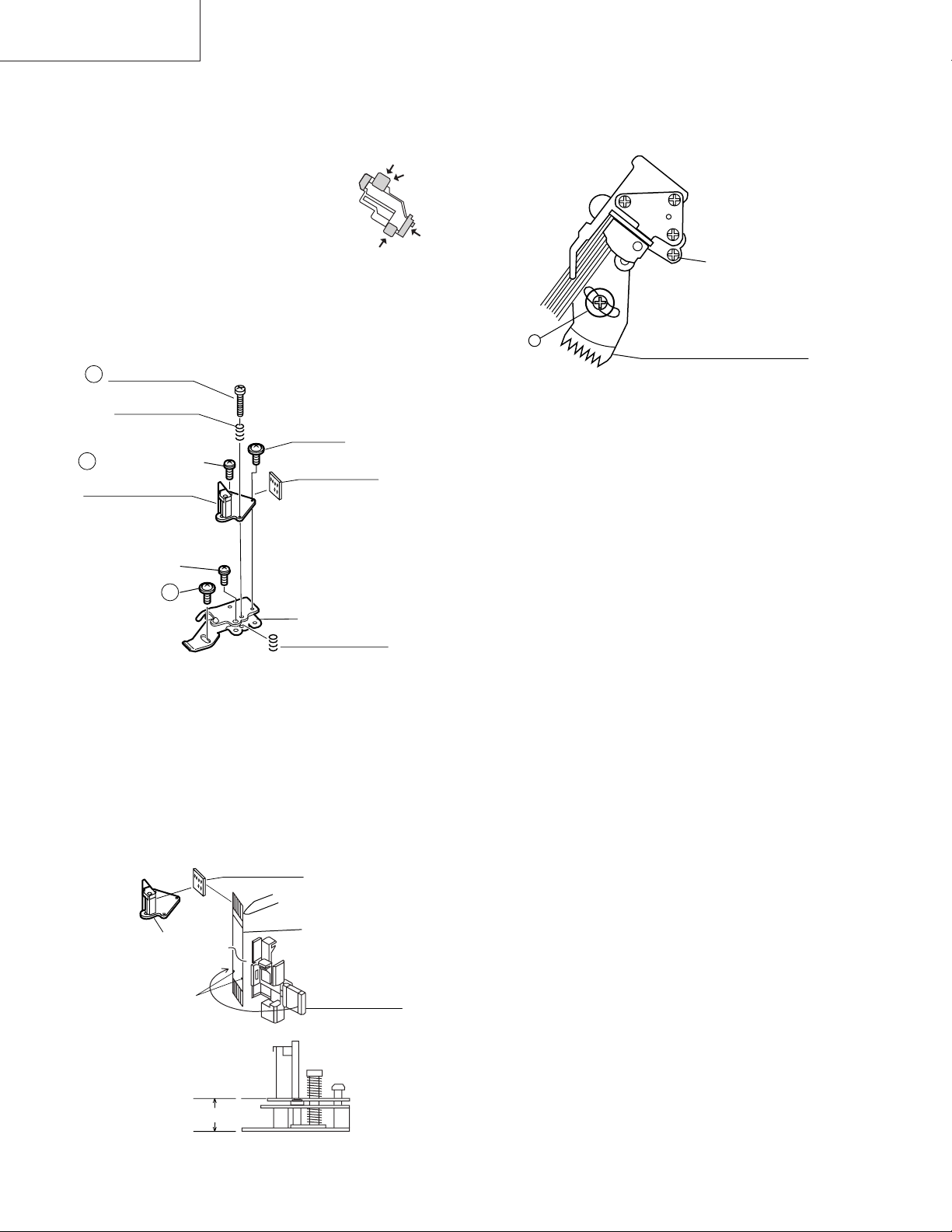
PRECAUTIONS IN PART REPLACEMENT
When servicing the unit with power on, be careful to the section marked white all over.
This is the primary power circuit which is live.
When checking the soldering side in the tape travel mode, make sure first that the tape has been loaded and then turn
over the PWB with due care to the primary power circuit.
Make readjustment, if needed after replacement of part, with the mechanism and its PWB in position in the main frame.
(1) Start and end sensors: Q701 and Q702
Insert the sensor’s projection deep into the upper hole of the holder. Referring to the PWB, fix the sensors tight
enough.
(2) Photocoupler: IC901 and IC902
Refer to the symbol on the PWB and the anode marking of the part.
(3) Cam switches A and B: S704.
Adjust the notch of the part to the white marker of the symbol on the PWB. Do not allow any looseness.
(4) Take-up and supply sensors: D707 and D706.
Be careful not to confuse the setting direction of the parts in reference to the symbols on the PWB. Do not allow any
looseness.
1. SPECIFICATIONS
Format: VHS PAL/MESECAM/NTSC standard (except VC-A60)
VHS PAL/SECAM/MESECAM/NTSC standard (VC-A60)
Video recording system: Rotary, slant azimuth two heads helical scan system
Video signal: PAL colour or monochrome (CCiR system B/G) signals
Maximum Recording/playing time: 240 minutes max. with SHARP E-240 tape at SP mode)
480 minutes max. with SHARP T-160 tape (NTSC: EP mode)
Tape width: 12.7mm
Tape speed: 23.39/33.53 mm/s (PAL/NTSC : SP mode)
11.70/16.67 mm/s (PAL/NTSC: LP mode)
7.79/11.12 mm/s (PAL/NTSC: EP mode)
Antenna: 75 ohm unbalanced
RF converter output signal: UHF Channel E21-E69 (preset to E60)
Power requirement: AC110-240V, 50/60Hz
Power consumption: Approx. 10W (VC-A10/A10S,VC-A50/A50S/A50S(B)/A500/A60)
Approx. 12W (VC-A75)
Approx. 13W (VC-A80S)
Operating temperature: 5°C to 40°C
Storage temperature: –20°C to 60°C
VIDEO Output: 1.0 Vp-p, 75 ohm
AUDIO Output: Line -8 dBs/1k ohm
Weight: Approx. 2.3 kg
Dimensions: 360 mm (W) x 232 mm (D) x 92 mm (H)
Accessories included: 75 ohm coaxial cable
Operation manual
Infrared remote control
Battery
Schematic Diagram (VC-A500)
As part of our policy of continuous improvement, we reserve the
right to alter design and specifications without notice.
Note: The antenna must correspond to the new standard DIN 45325
(IEC 169 - 2) for combined UHF/VHF antenna with 75 ohm connector.
2
Page 3
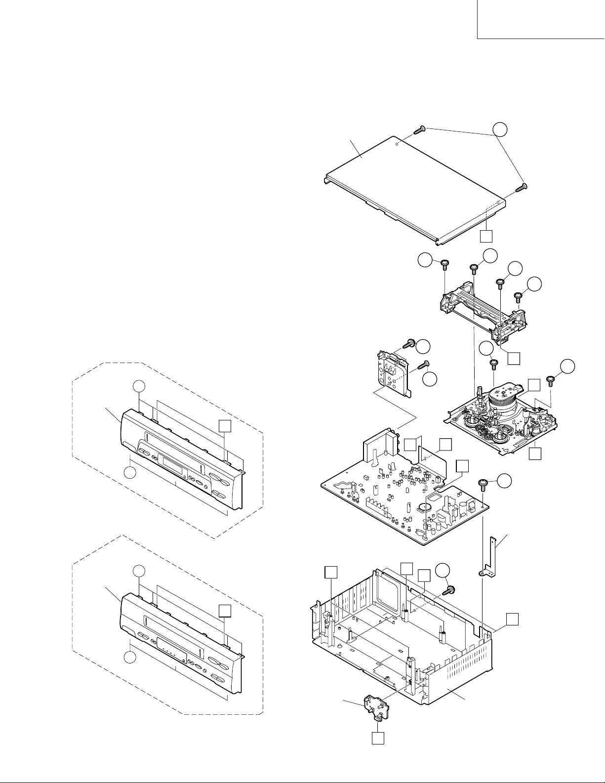
2. DISASSEMBLY AND REASSEMBLY
2-1 DISASSEMBLY OF MAJOR BLOCKS
TOP CABINET : Remove 2 screws 1.
FRONT PANEL : Remove 2 screws 2 and 7 clips 3.
MECHANISM/ : Remove 2 screw 4, 2 screws 5.
MAIN PWB Remove 2 screws 6 with antenna
terminal cover. Remove 1 screw 7
with top cabinet fix angle.
TOP CABINET
VC-A10/A10S/A500
VC-A50/A50S/A50SB
VC-A60/A75/A80S
1
C
VC-GH61GM/SM
FRONT PANEL
2
6
3
B
3
6
A
A
4
2
4
5
B
5
A
E
D
7
TOP CABINET
FIX ANGLE
FRONT PANEL
3
B
3
OPERATION PWB
VC-GH611GM/SM
B
E
D
4
A
C
MAIN FRAME
3
Page 4
VC-A10/A10S/A500
VC-A50/A50S/A50SB
VC-A60/A75/A80S
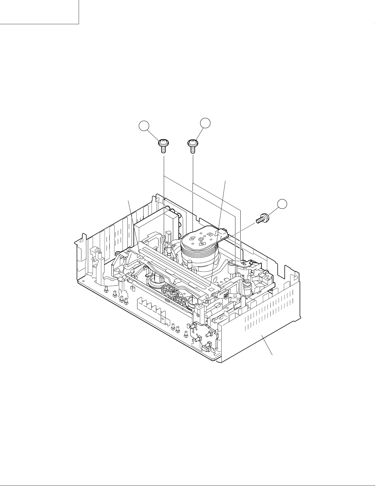
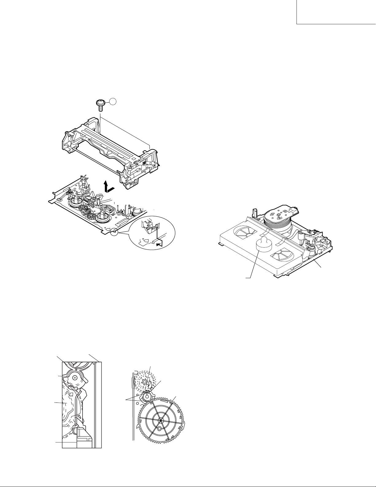
2-2 DISASSEMBLING THE MECHANISM
1. When removing the mechanism from the set.
Remove the screw 2 which connecting the PWB and
the mechanism.
Remove the screw 4 which connecting mechanism and
main frame.
Take out vertically the mechanism so that it does not
damage the adjacent parts.
3
CASSETTE
HOUSING
2. Removing the mechanism and cassette housing.
Remove 2 screws 3 fixing the cassette housing to the
mechanism, and remove the cassette housing.
4
MECHANISM CHASSIS
2
MAIN FRAME
4
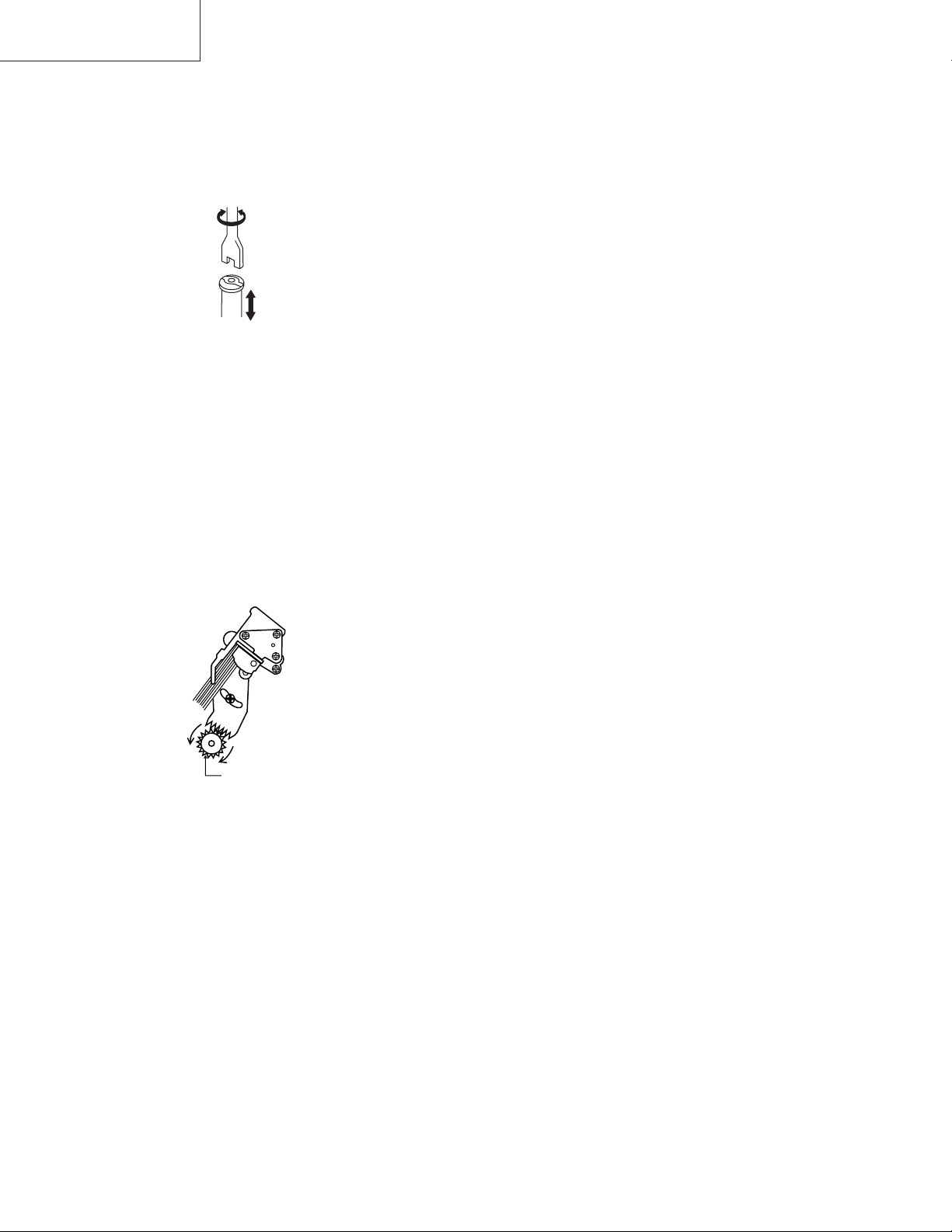
Page 5
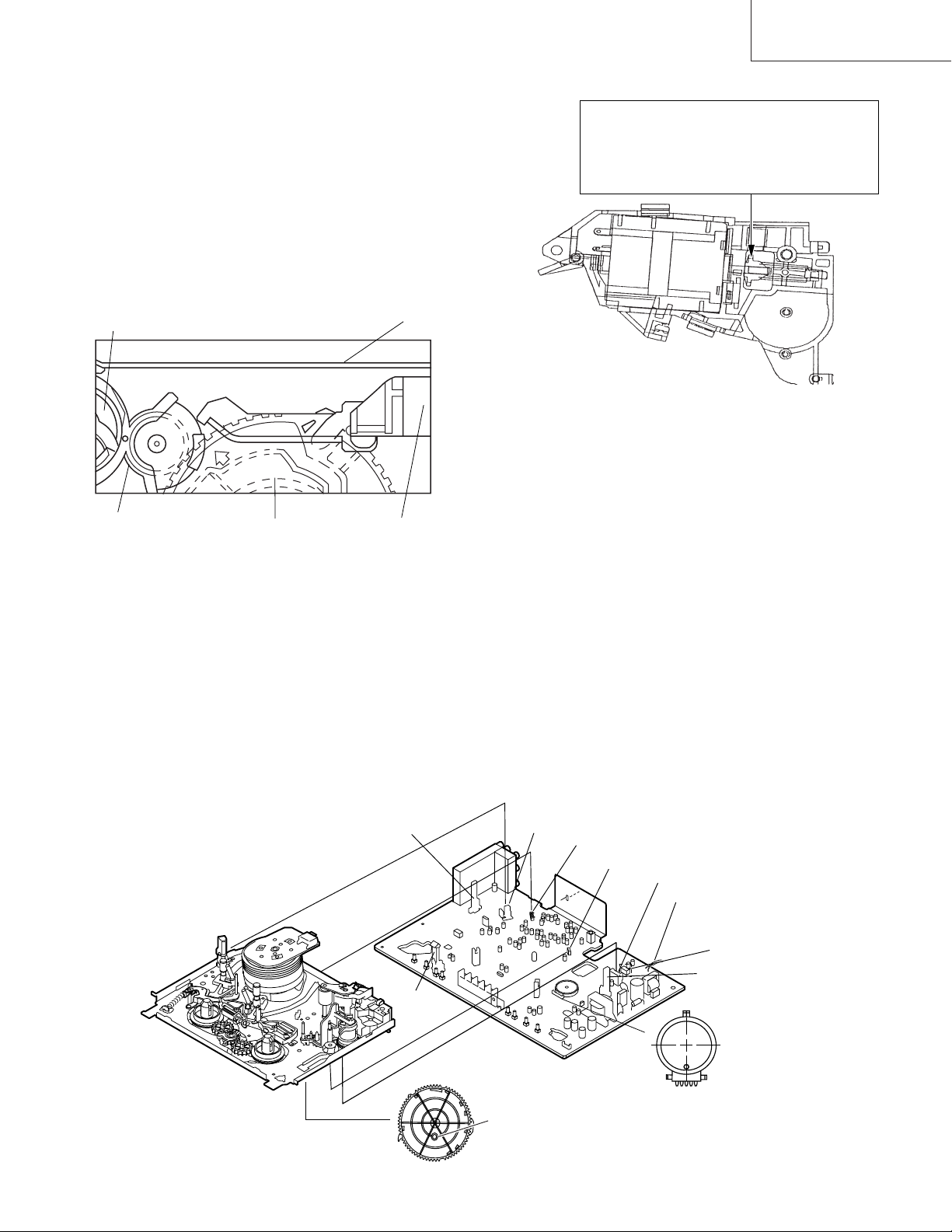
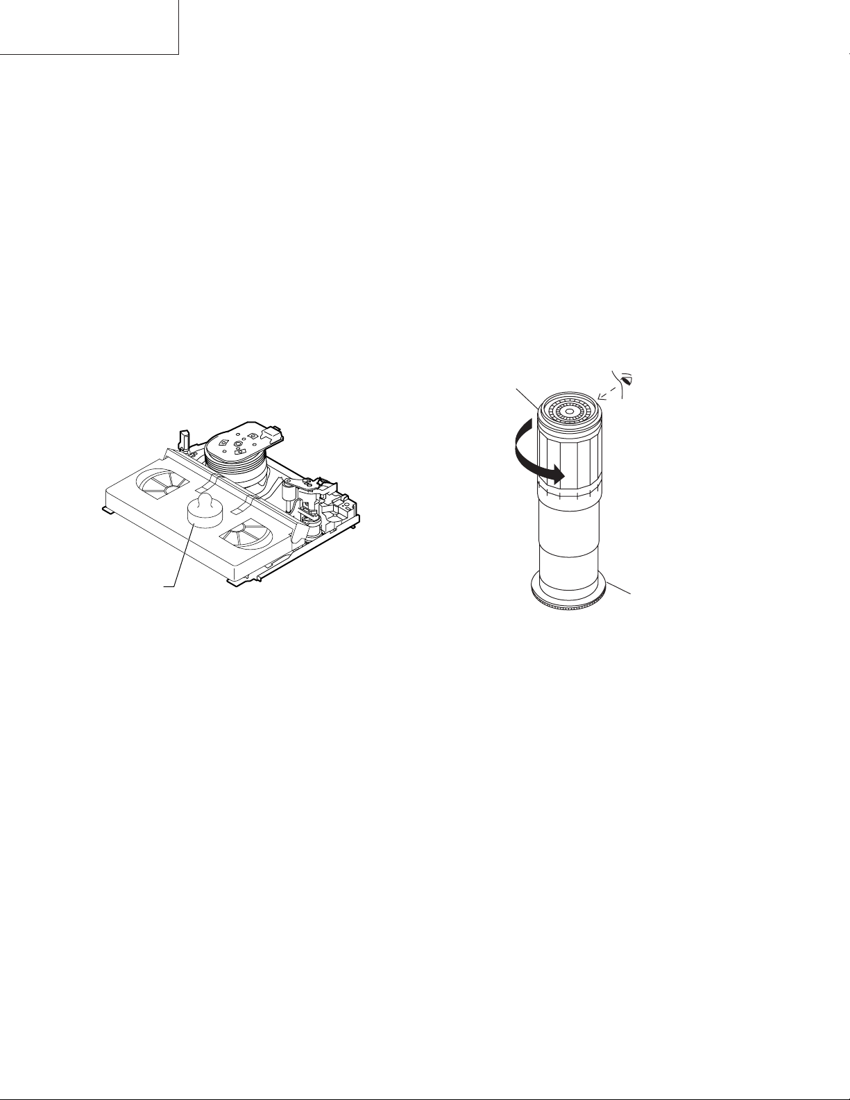
2-3 CARES WHEN REASSEMBLING
Rotate the flange of worm gear by using thin stick.
CW • • • Loading direction
CCW • • • Ejection direction
Note:
Be careful not to damage the gear of worm gear and
worm wheel gear. It miight cause a strange sound.
INSTALLING THE CASSETTE HOUSING
When the cassette housing is installed on the mechanism,
the initial setting is essential condition.
There are two initial setting methods, namely electrical and
mechanical.
1. Electrical initial setting
So as to perform initial setting of mechanism execute the
Step 1 of Installation of cassette housing. After ascertaining
the return to the initial setting position install the cassette
housing. (Conditions: When mechanism and PWB have
been installed)
Pinch Drive Cam
Synchro Gear
Master cam
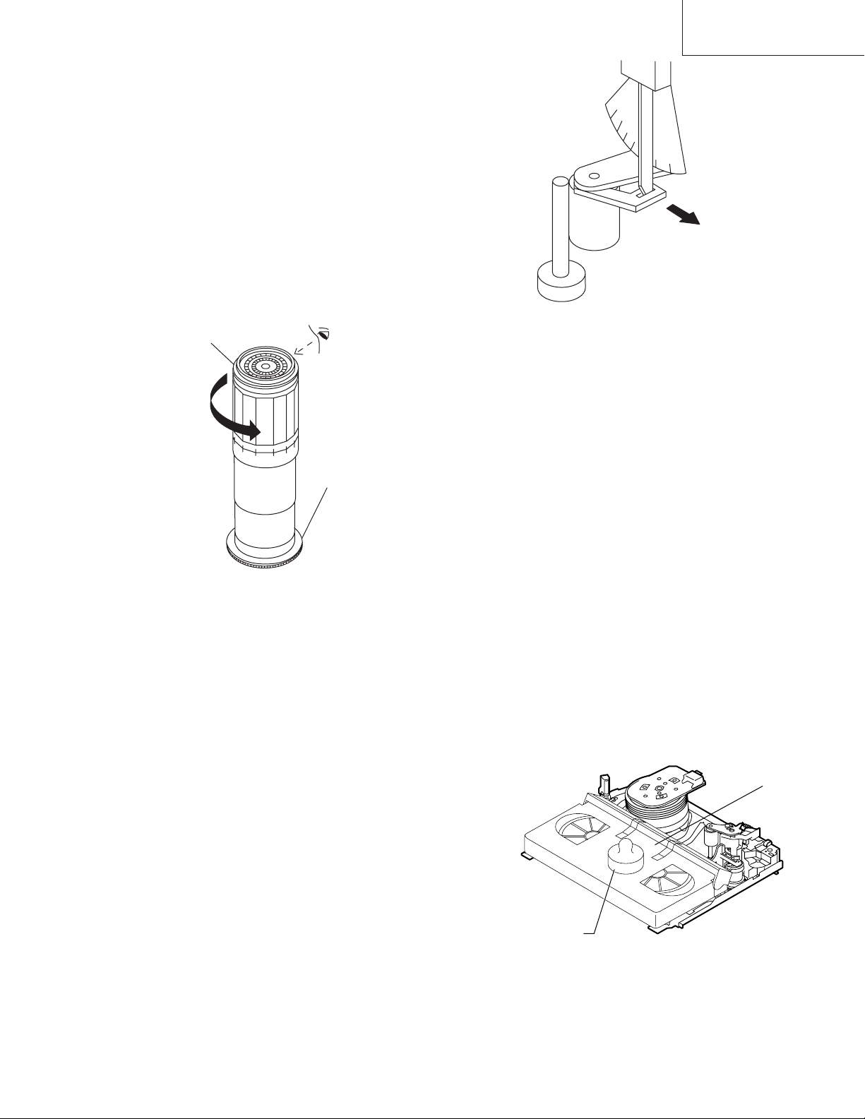
2. Mechanical initial setting
• Rotate the worm gear by pushing the flange manually until
return to initial position.
Main Chassis
Drive Lever
VC-A10/A10S/A500
VC-A50/A50S/A50SB
VC-A60/A75/A80S
• When apply power supply to rotate the loading motor,
please remove/unsolder at least one terminal wire.
• If voltage applied to loading motor without diconnecting
the terminal wire, there is a possibility the capstan motor
IC will damage.
• The maximum applied voltage is 9V. If more than 9V,
there is apossibility the mechanism will damage.
• After ascertaining the return to the initial set position
install the cassette housing in the specified position. (This
method is applied only for the mechanism.)
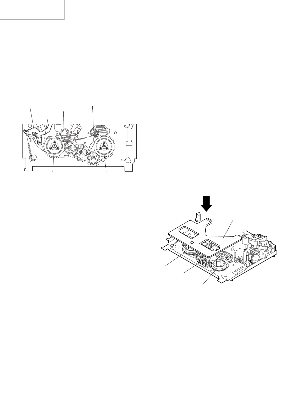
INSTALLING THE MECHANISM ON PWB
Lower vertically the mechanism, paying attention to the
mechanism edge mode SW position, (Set the mode SW
position to 270° and make sure the master cam position
hole also in 270° position) and install the mechanism with
due care so that the parts are not damaged.
* Please make sure to insert correctly.
If not, strange moving will occur and will couse mecha-
nism damage.
END SENSOR
END TIP SW
PARTS WHICH NEED PARTICULAR CARE
When installing the mechanism chassis on the PWB unit,
take care so as to prevent deformation due to contact of
mechanism chassis with REC TIP SW.
AE CONNECTOR
AH CONNECTOR
AA CONNECTOR
AD CONNECTOR
AC CORD
VC-A50 only
START SENSOR
90°
0°
This positioning hole
should be at front side.
180°
270°
MODE SW
MASTER CAM POSITION
5
Page 6
VC-A10/A10S/A500
VC-A50/A50S/A50SB
VC-A60/A75/A80S
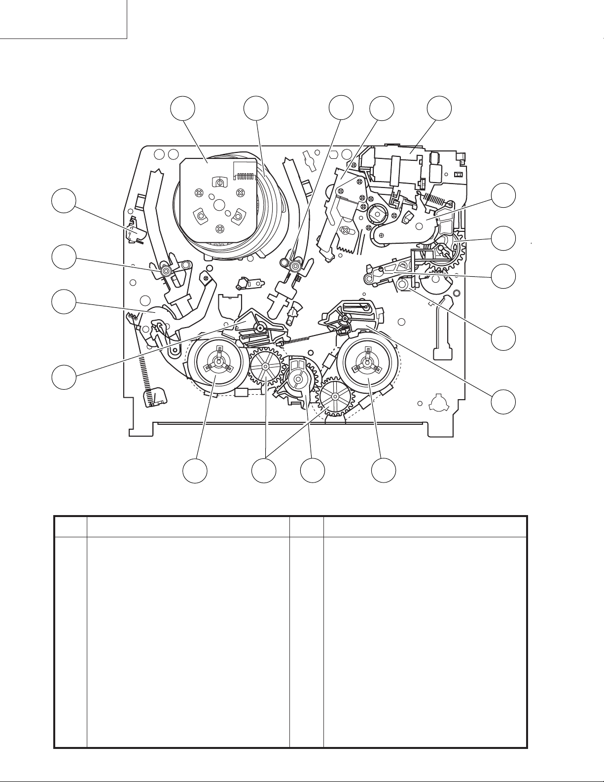
3. FUNCTION OF MAJOR MECHANICAL PARTS (TOP VIEW)
17
15
1
18
10
16
14
9
2
11
3
5
7
6
No. Function
1 Full erase head
2 Supply pole base ass’y
3 Tension arm
4 Idler wheel ass’y
5 Open guide
6 Supply reel disk
7 Supply main brake
12
4
13
No. Function
11 Reverse guide lever ass’y
12 Reel relay gear
13 Take-up reel disk
14 Pinch roller lever ass’y
15 Drum ass'y
16 Loading motor block
17 Drum driver motor
8
8 Take-up main brake
9 Pinch drive cam
10 A/C head ass’y
18 Take-up pole base ass'
6
Page 7
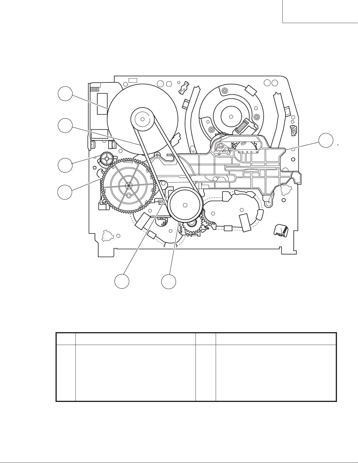
FUNCTION OF MAJOR MECHANICAL PARTS (BOTTOM VIEW)
(except VC-A50S)
21
22
VC-A10/A10S/A500
VC-A50/A50S/A50SB
VC-A60/A75/A80S
19
20
23
24
25
No. Function
19 Syncro Gear
20 Master cam
21 Capstan D.D. motor
22 Reel belt
No. Function
23 Clutch lever
24 Limiter pulley ass’y
25 Shifter
7
Page 8
VC-A10/A10S/A500
VC-A50/A50S/A50SB
VC-A60/A75/A80S
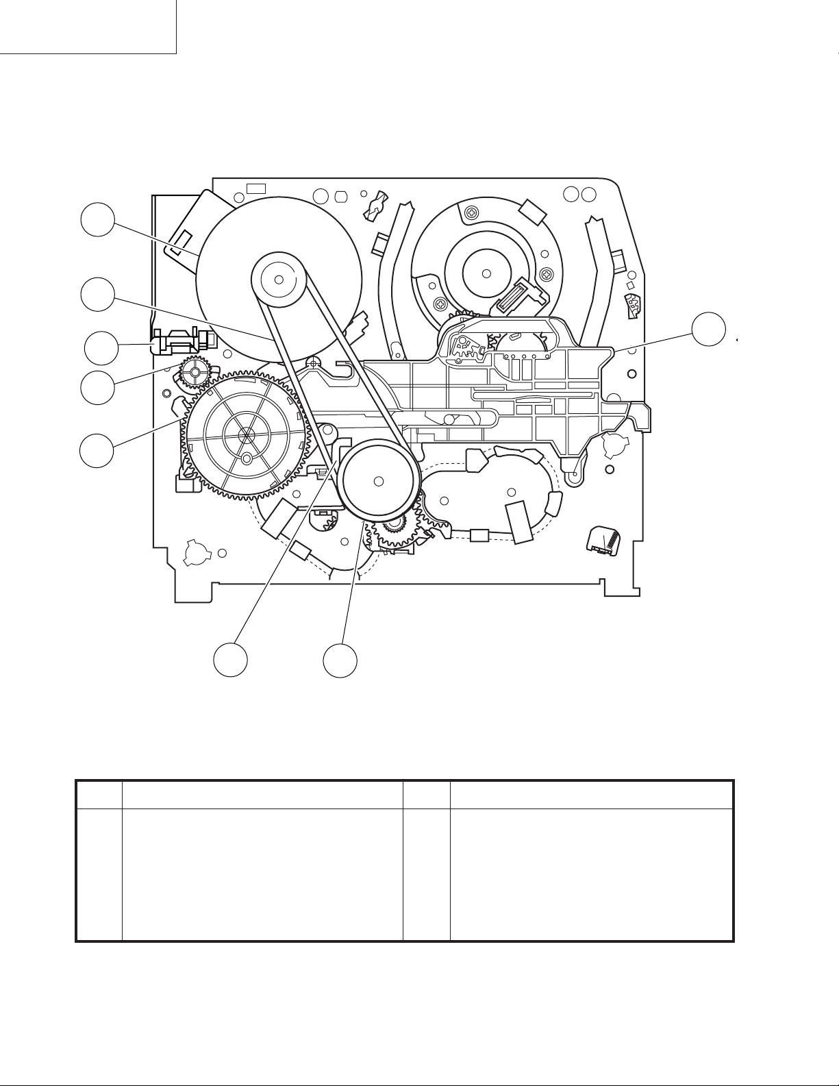
FUNCTION OF MAJOR MECHANICAL PARTS (BOTTOM VIEW)
(VC-A50S)
21
22
26
19
20
23
24
25
No. Function
19 Syncro Gear
20 Master cam
21 Capstan D.D. motor
22 Reel belt
No. Function
23 Clutch lever
24 Limiter pulley ass’y
25 Shifter
26 DM/LM FFC Holder
8
Page 9
VC-A10/A10S/A500
VC-A50/A50S/A50SB
VC-A60/A75/A80S
4. ADJUSTMENT, REPLACEMENT AND ASSEMBLY OF MECHANICAL UNITS
The explanation given below relates to the on-site general service (field service) but it does not relates to the adjustment
and replacement which need high-grade equipment, jigs and skill. For example, the drum assembling, replacement and
adjustment service must be performed by the person who have finished the technical courses.
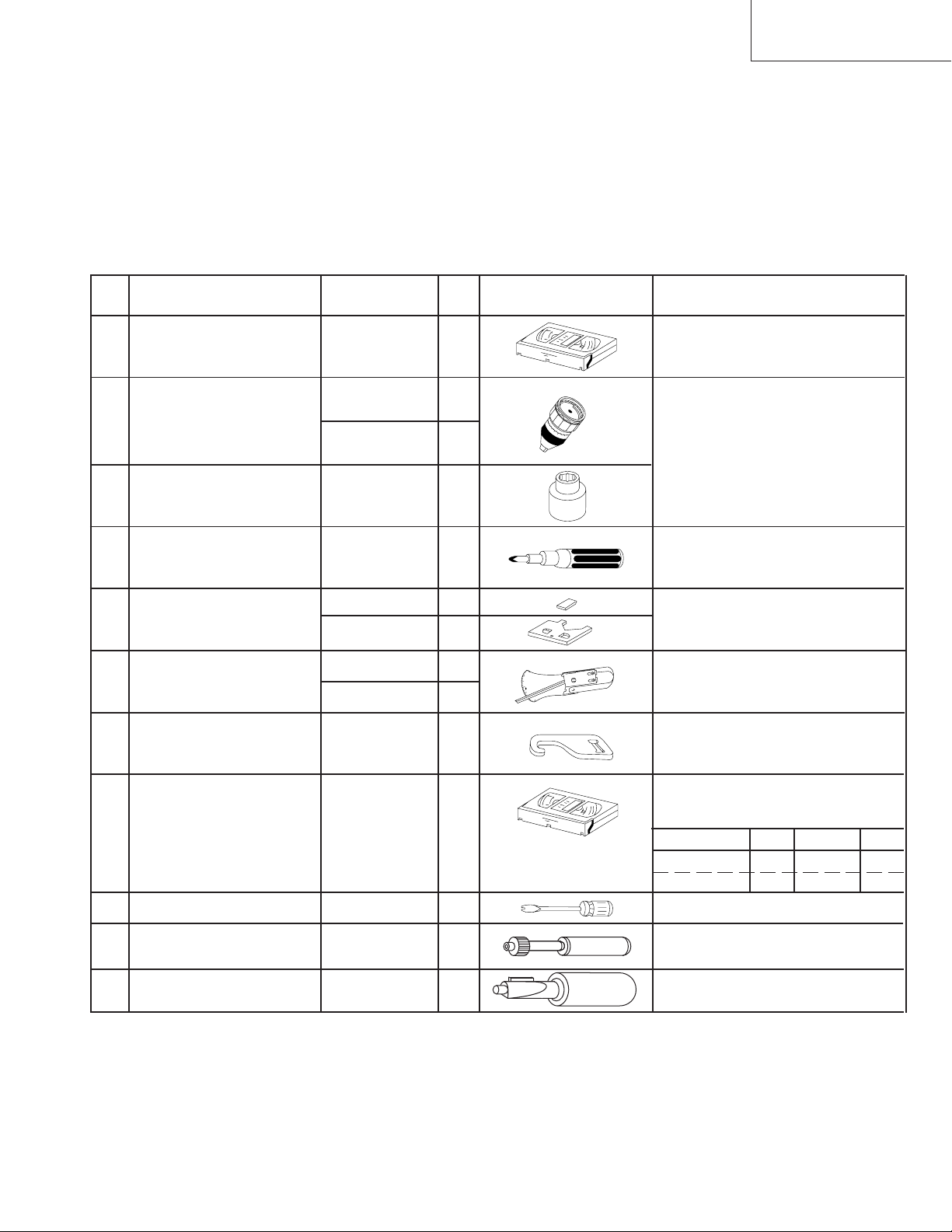
4-1 MECHANISM CONFIRMATION ADJUSTMENT JIG
So as to perform completely the mechanism adjustment prepare the following special jigs. So as to maintain the initial
performance of the machine the maintenance and check are necessary. Utmost care must be taken so that the tape is
not damaged. If adjustment needs any jig, be sure to use the required jig.
No. Jig ltem Part No. Code Configuration Remarks
This cassette torque meter is used for check-
1. Torque Cassette Meter JiGVHT-063 CZ
JiGTG0090 CM
2.
Torque Gauge
JiGTG1200 CN
3. Torque Gauge Head JiGTH0006 AW
ing and adjusting the torque of take-up for
measuring tape back tension.
These Jigs are used for checking
and adjusting the torque of take-up
and supply reel disks.
4. Torque Driver JiGTD1200 CB
Master Plane Jig and
Reel Disk Height
5.
Adjusting Jig
JiGRH0002 BR
JiGMP0001 BY
JiGSG2000 BS
Tension Gauge
6.
JiGSG0300 BF
Pinch pressing force
7. JiGADP003 BK
measuring jig
8.
Alignment Tape
Guide roller height
9. JiGDRiVERH-4 AP
adjustment driver
X value adjustment
10. JiGDRiVER-6 BM
gear driver
Tension Pole
11. JiGHMEC-M005
Adjustment Driver
VROCPSV CK
When fixing any part to the threaded
hole using resin with screw, use the
jig. (Specified torque 5 kg)
These Jigs are used for checking
and adjusting the reel disk height.
There are two gauges used for the
tension measurements, 300 g and
2.0 kg.
This Jig is used with the tension
gauge. Rotary transformer clearance
adjusting jig.
These tapes are especially used for
electrical fine adjustment.
Video Audio HiFi Audio Track
625 Monoscope 7k — 49µm
PAL Colour Bar 1k — 49µm
This screwdriver is used for adjusting the
guide roller height.
For X value adjustment
This Jig is used for adjustment
of tension pole.
9
Page 10
VC-A10/A10S/A500
VC-A50/A50S/A50SB
VC-A60/A75/A80S
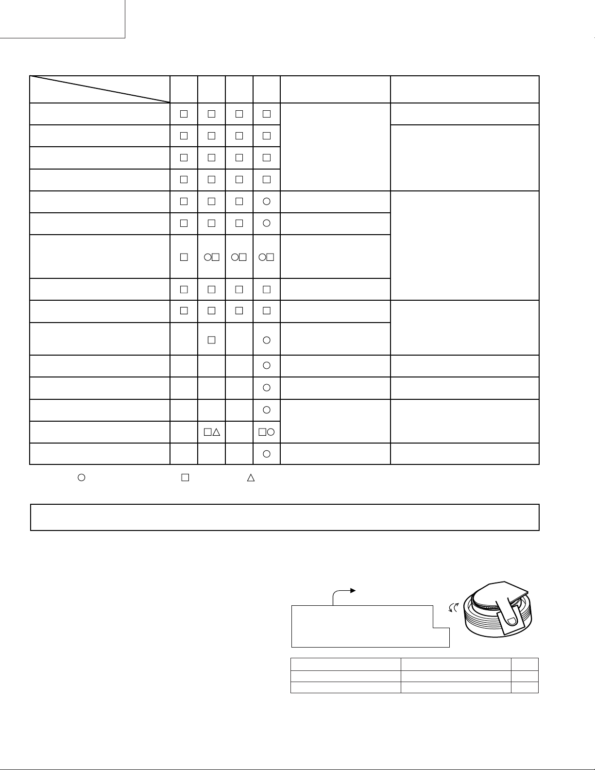
4-2 MAINTENANCE CHECK ITEMS AND EXECUTION TIME
Perform the maintenance with the regular intervals as follows so as to maintain the quality of machine.
Possible symptom
encountered
Abnormal rotation or significant
vibration requires replacement.
Parts
Guide roller ass’y
Maintained
500
hrs.
1000
hrs.
1500
hrs.
2000
hrs.
Remarks
Sup guide shaft
Reverse guide
Slant pole on pole base
Full erase head
A/C head
Upper and lower drum ass’y
Capstan D.D. motor
Pinch roller
Reel belt
Tension band ass’y
Loading motor
Idler ass’y
Limiter pulley
Lateral noises Head
occasionally blocked
Colour and beating
Small sound or sound
distortion
Poor S/N ratio, no colour
Poor flatness of the
envelope with alignment
tape
No tape running,
uneven colour
No tape running, tape
slack
No tape running, tape
slack, no fast forward/
rewind motion
Screen swaying
Cassette not loaded or
unloaded
No tape running, tape
slack
Clean tape contact part with the
specified cleaning liquid.
Clean tape contact area with the
specified cleaning liquid.
Clean rubber and rubber contact
area with the specified cleaning
liquid.
Supply/take-up main brake levers
Tape slack
NOTE : Part replacement. : Cleaning : Apply grease
<Specified> Cleaning liquid Industrial ethyl alcohol
* This mechanism does not need electric adjustment with variable resistor. Check parts. If any deviation is found,
clean or replace parts.
Video head cleaning procedure
1. Apply one drop of cleaning liquid to the cleaning paper with the baby oiler.
2. Gently press the cleaning paper against the video head to fix your finger, and move the upper drum so that each head
is passed to and fro 5 times (do not move the cleaning paper).
3. Wipe with the dry cleaning paper.
Notes :
• Use the commercially available ethanol of Class 1 as
cleaning liquid.
• Since the video head may be damaged, do not move up
and down the cleaning paper.
Gently press the cleaning paper to
fix with your finger, and rotate the
upper drum to clean.
Move to and fro 5 times for each head.
(Do not move the cleaning paper.)
Rotate the upper drum
with one hand.
• Whenever the video head is cleaned, replace the cleaning paper.
• Do not apply this procedure for the parts other than the
video head.
Parts Code Description Code
ZPAPRA56-001E Cleaning Paper AW
ZOiLR-02-24TE Babe Oiler (Spoit) AH
10
Page 11
4-3 REMOVING AND INSTALLING THE CAS-
SETTE HOUSING
• Removal
1. In the cassette removing mode, remove the cassette.
2. Unplug the power cord.
3. Remove in the following numerical order.
a) Remove two screws 1.
b) Pull and circle the drive lever and pull up the cassette
housing control.
1
VC-A10/A10S/A500
VC-A50/A50S/A50SB
VC-A60/A75/A80S
2. Install in the reverse order of removal.
Notes
1. In the case when you use the magnet screw driver, never
approach the magnet driver to the A/C head, FE head,
and drum.
2. When installing or removing, take care so that the
cassette housing control and tool do not contact the
guide pin or drum.
3. After installing the cassette housing control once perform cassette loading operation.
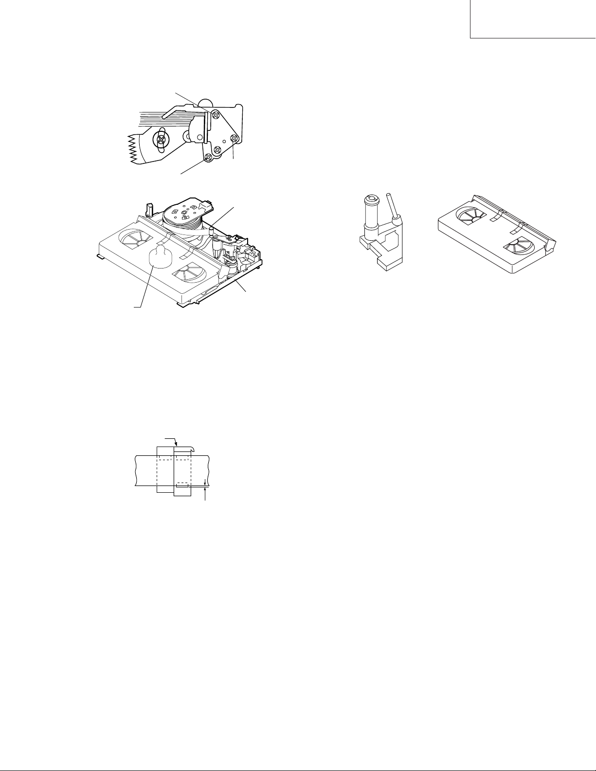
4-4 TO RUN A TAPE WITHOUT THE CASSETTE
HOUSING CONTROL ASSEMBLY
1. Remove the full-surface panel.
2. Short-circuit between TP803 and TP802.
3. Plug in the power cord.
4. Turn off the power switch.
(The pole bases move into U.L.position.)
5. Open the lid of a cassette tape by hand.
6. Hold the lid with two pieces of vinyl tape.
7. Set the cassette tape in the mechanism chassis.
8. Stabilize the cassette tape with a weight (500g) to
prevent floating.
Figure 4-1.
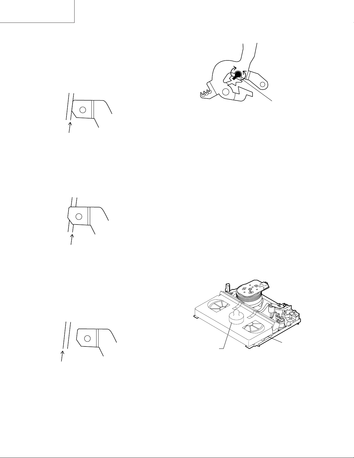
• Reassembly
1. Before installing the cassette housing control, shortcircuit between TP803 and TP802 provided at main
PWB, press the eject button. The master cam turns and
stop in eject position. Fit the drive lever to master cam
through main chassis, push down and slide the drive
lever towards to master cam.
*Eject position: Pinch Drive Cam positioning hole parallel to center of Synchro Gear (Synchro gear marking
line). Synchro Gear positioning mark parallel to center
of master cam.
Pinch Drive
Cam
Synchro
Gear
Master
cam
Main chassis
Phase
matching
Hole of Pinch
drive cam.
Line of
synchro
gear.
Master cam
500g
Mechanism chassis
Weight to prevent
float (500g)
Figure 4-3.
9. Turn on the power switch.
10. Perform running test.
Note:
The weight should not be more than 500g.
To take out the cassette tape.
1. Turn off the power switch.
2. Take out the cassette tape.
Drive
Lever
From top view
From Bottom View
Figure 4-2.
11
Page 12
VC-A10/A10S/A500
VC-A50/A50S/A50SB
VC-A60/A75/A80S
4-5 REEL DISK REPLACEMENT AND HEIGHT
CHECK
• Removal
1. Remove the cassette housing control assembly.
2. Remove the Supply/Take-up main brake ass'y.
3. Remove tension band from the tension arm ass'y.
4. Remove the reel disk.
Note:
Take care so that the tension band ass'y and main brake
ass'y are not deformed.
Tension arm ass'y
Ten
Tension band
ass'y
Supply main brake
Take-up main brake ass'y
Notes:
1. When installing the reel disk, take due care so that the
tension band ass'y is not deformed and grease does no
adhere.
2. Do not damage the Supply main brake ass'y. Be careful
so that grease does not adhere to the brake surface.
• Reassembly (Take-up reel disk)
1. Clean the reel disk shaft and apply grease (SC-141) to
it.
2. Align the phase of the reel disk to that of the reel relay
gear and to install a new take-up reel disk onto the shaft.
3. Check the reel disk height and reassemble the take-up
main brake ass'y.
Note:
1. Take care so that the Take-up main brake ass'y is not
damaged. Take care so that grease does not adhere the
brake surface.
2. After reassembly, check the video search rewind back
tension (see 4-10), and check the brake torque (see 4-
14).
Take-up reel diskSupply reel disk
• Reassembly (Supply reel disk)
1. Clean the reel disk shaft and apply grease (SC-141) to
it.
2. Match the phases of reel disk and reel relay gear, and set
the new reel disk.
3. After checking the reel disk height, wind the tension
band ass'y around the reel disk, and hook to tension arm
ass'y.
4. Assemble the Supply main brake ass'y.
• Height checking and adjustment
Note:
1. Set the master plane with due care so that it does not
contact the drum.
2. When putting the master plane, shift the reverse guide
a little in the loading direction. Care must be taken since
excessive shift results in damage.
Master plane
Supply reel disk
Cassette lock
release shaft
Take-up reel disk
Figure 4-4.
Note:
• Check that the reel disk is lower than part A but higher
than part B. If the height is not correct, readjust the reel
disk height by changing the poly-slider washer under the
reel disk.
12
Page 13
Note:
Whenever replacing the reel disk, perform the height checking and adjustment.
Master plane
10 ± 0.2mm
Reel disk
Reel disk
Reel disk height
adjusting jig
Mechanism chassis
A
B
Figure 4-5.
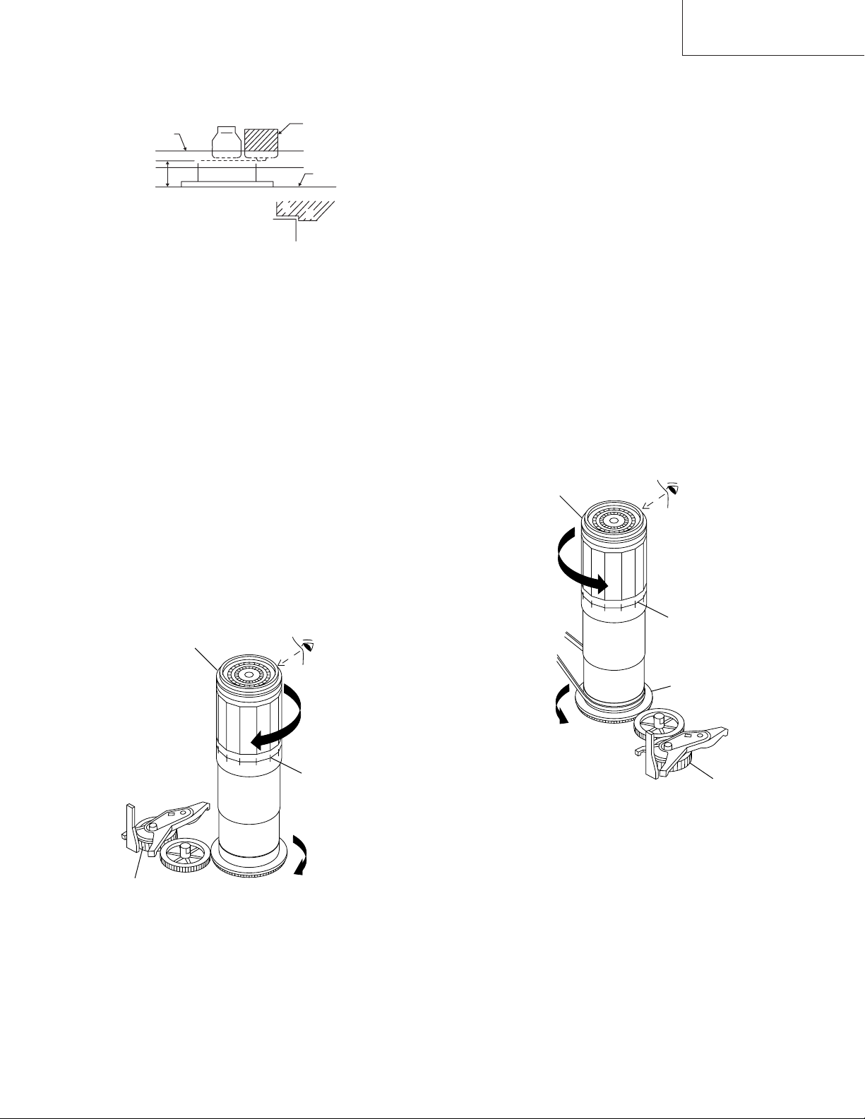
4-6 CHECKING AND ADJUSTMENT OF TAKE-
UP TORQUE IN FAST FORWARD MODE
• Remove the cassette housing control assembly.
• After short-circuiting between TP803 and TP802
provided at main PWB, plug in the power cord.
• Setting
1. Set a torque gauge to zero on the scale. Place it on the
take-up reel disk.
2. Press the FF button.
3. To calculate the remaining capacity of the play back
mode, slowly rotate the supply reel disk, and then shift
it into the forward mode.
VC-A10/A10S/A500
VC-A50/A50S/A50SB
VC-A60/A75/A80S
Notes:
1. Hold the torque gauge by hand so that it is not moved.
2. Do not keep the reel disk in lock state. Do not allow longtime measurement.
4-7 CHECKING AND ADJUSTMENT OF TAKE-
UP TORQUE IN REWIND MODE
• Remove the cassette housing control assembly.
• After short-circuiting between TP803 and TP802
provided at main PWB, plug in the power cord.
• Setting
1. Set a torque gauge to zero on the scale. Place it on the
supply reel disk.
2. Press the rewind button.
3. To calculate the remaining capacity, slowly rotate the
take-up reel disk, and then shift it into the rewind mode.
• Checking
1. Turn the torque gauge slowly (one rotation every 2 to 3
seconds) by hand in the CCW direction.
2. Make sure that the indication of torque gauge is not less
than 30mN·m (306gf·cm).
Torque gauge 3
• Checking
1. Turn the torque gauge slowly (one rotation every 2 to 3
seconds) by hand in the CW direction.
2. Make sure that the indication of torque gauge is not less
than 30mN·m (306gf·cm).
Torque gauge
30mN·m (306gf·cm)
or more
Idler ass'y
CW
The gauge is held at
its maximum value.
(Red mark)
Figure 4-6.
• Adjustment
1. If the FF winding-up torque is less than the specified
value, clean the capstan D.D. pulley, reel belt, and
limiter pulley with cleaning liquid, and check again.
2. If the torque is less than the set value, replace the reel
belt.
30mN·m (306gf·cm)
or more
CCW
The gauge is held at
its maximum value.
(Red mark)
Supply reel disk
Idler ass'y
Figure 4-7.
• Adjustment
1. If the rewind winding-up torque is less than the specified
value, clean the capstan D.D. pulley, reel belt, and
limiter pulley with cleaning liquid, rewind again, and
check the winding-up torque.
2. If the winding-up torque is still out of range, replace the
drive belt.
13
Page 14
VC-A10/A10S/A500
VC-A50/A50S/A50SB
VC-A60/A75/A80S
Notes:
1. Hold the torque gauge by hand so that it is not moved.
2. Do not keep the reel disk in lock state. Do not allow longtime measurement.
4-9 CHECKING AND ADJUSTMENT OF TAKE-
UP TORQUE IN VIDEO SEARCH REWIND
MODE
• Remove the cassette housing control assembly.
4-8 CHECKING AND ADJUSTMENT OF TAKE-
UP TORQUE IN RECORD/PLAYBACK
MODE
• Remove the cassette housing control assembly.
• After short-circuiting between TP803 and TP802
provided at main PWB, plug in the power cord.
• Turn off the power switch.
• Open the cassette torque meter lid, and fix it with
tape.
• Load the cassette torque meter into the unit.
• Put the weight (500g) on the cassette torque meter.
• Turn on the power switch.
• Press the picture record button, and set LP picture
record mode (x2).
Set value LP 6.9
+2.0
mN⋅m (70
–2.5
500g
+20
–25
gf⋅cm)
• After short-circuiting between TP803 and TP802
provided at main PWB, plug in the power cord.
• Setting
Press the playback button and rewind button to set the
video search rewinding mode.
• Checking
Place the torque gauge on the supply reel disk, and turn it
counterclockwise very slowly (one rotation every 1 to 2
seconds) and check that the torque is within the set value
14.1 ± 3.5mN⋅m. (144 ± 35gf⋅cm)
Torque gauge
CCW
Cassette torque meter
Figure 4-8.
• Checking
1. Make sure that value is within the setting 6.9 mN·m
+20
(70 gf·cm).
–25
+2.0
–2.5
2. The winding-up torque fluctuates due to variation of
rotation torque of limiter pulley ass'y. Read the center
value of fluctuation as setting.
3. Set the LP record mode (x2) and make sure that the
winding-up torque is within setting.
• Adjustment
If the playback winding-up torque is not within the setting,
replace the limiter pulley assembly.
Note:
When the torque cassette is set, put a weight (500g) to
prevent rise.
When the cassette torque meter is taken out.
Turn off the power switch.
Supply reel disk
Figure 4-9.
Note:
Surely put the torque gauge on the reel disk to measure. If
the torque gauge is raised, accurate measurement is
impossible.
• Adjustment
If the rewinding playback winding-up torque is not within the
setting, replace the limiter pulley assembly.
Note:
The winding-up torque fluctuates due to variation of rotation torque of supply reel disk. Read the center value of
fluctuation as setting.
14
Page 15
4-10 CHECKING THE VIDEO SEARCH REWIND
500g
Weight to prevent
float (500g)
(E-180)
BACK TENSION
• Remove the cassette housing control assembly.
VC-A10/A10S/A500
VC-A50/A50S/A50SB
VC-A60/A75/A80S
• After short-circuiting between TP803 and TP802
provided at main PWB, plug in the power cord.
• Checking
1. After pressing the play button, press the rewind button,
and set the video search rewind mode.
2. Place the torque gauge on the take-up reel disk, and turn
it counterclockwise very slowly (one rotation every 2 to
3 seconds) and check that the torque is within the set
value 3.7 ± 1.5mN⋅m (38 ± 15gf⋅cm).
Torque gauge
CCW
Take-up reel disk
Pinch roller
Capstan shaft
Tension gauge adapter
Tension gauge
900 - 1,200gf
Figure 4-11.
4-12 CHECKING AND ADJUSTMENT OF
TENSION POLE POSITION
∗∗
∗ Checking can be perform with or without
∗∗
cassette housing control.
• Remove the cassette housing control assembly.
• After short-circuiting between TP803 and TP802 provided at main PWB, plug in the power cord.
Figure 4-10.
Notes:
Set the torque gauge securely on the take-up reel disk.
If it is not secure, the measurement will be incorrect.
4-11 CHECKING THE PINCH ROLLER
PRESSURE
∗∗
∗ Checking can be perform with or without
∗∗
cassette housing control.
• Remove the cassette housing control assembly.
• After short-circuiting between TP803 and TP802 provided at main PWB, plug in the power cord.
• Checking
Press the play button to set the playback mode.
1. Detach the pinch roller from the capstan shaft.
Do not separate excessively. Or the pinch lever and
pinch double action lever may disengage.
2. Engage the tension gauge adapter with the pinch roller
shaft, and pull in the arrow direction.
3. Gradually return the pinch roller, and measure the pulling force when the pinch roller contacts the capstan
shaft.
4. Make sure that the measured value is within setting
change to 9.8 ± 2N (1.0 ± 0.2kgf).
• Setting (without cassette housing control)
1. Turn off the power switch.
2. Open the cassette tape (E-180), and fix with tape.
3. Set the cassette tape in loading state.
4. Put the weight (500g) on the cassette tape.
5. Turn on the power switch.
6. Make the adjustment with the beginning of a E-180 tape.
• Setting (with cassette housing control)
1. Insert cassette tape (E-180).
2. Make the adjustment with the beginning of a E-180
tape.
Figure 4-12.
15
Page 16
VC-A10/A10S/A500
VC-A50/A50S/A50SB
VC-A60/A75/A80S
• Checking
1. Set a cassette tape, push the REC button to place the
unit in the SP record mode. Now check the tension pole
position.
2. Visually check to see if the position of the tension pole is
within the 0 mm from the left side line.
+ 0.5
– 0.2
Standard A = 0 mm
A
+ 0.5
- 0.2
Tension pole adjustment driver adjusting direction
CCW
CW
Tension pole
adjustment
driver
Figure 4-16.
Make the adjustment with the beginning of a E-180 tape.
Figure 4-13.
At left side from the reference line. (A).
A
Figure 4-14.
Insert the tension pole adjustment driver to main chassis
hole, and rotate clockwise.
At right side from the reference line. (A).
4-13 CHECKING AND ADJUSTMENT OF
RECORD/PLAYBACK BACK TENSION
∗∗
∗ Checking can be perform with or without
∗∗
cassette housing control.
• Remove the cassette housing control assembly.
• After short-circuiting between TP803 and TP802 provided at main PWB, plug in the power cord.
• Setting (without cassette housing control)
1. Turn off the power switch.
2. Open the cassette torque meter and fix with tape.
3. Set the cassette torque meter in loading state.
4. Put the weight (500g) on the cassette torque meter.
5. Turn on the power switch.
• Setting (with cassette housing control)
1. Insert cassette torque meter.
A
Figure 4-15.
Insert the tension pole adjustment driver to main chassis
hole, and rotate counterclockwise.
500g
Cassette torque
Weight to prevent
float (500g)
meter
Figure 4-17.
• Checking
1. Push the REC button to place the unit in the SP record
mode.
2. At this time ascertain that the back tension is within the
setting 3.9 to 5.5mN⋅m (40 to 56gf·cm) by seeing the
indication of torque cassette meter.
16
Page 17
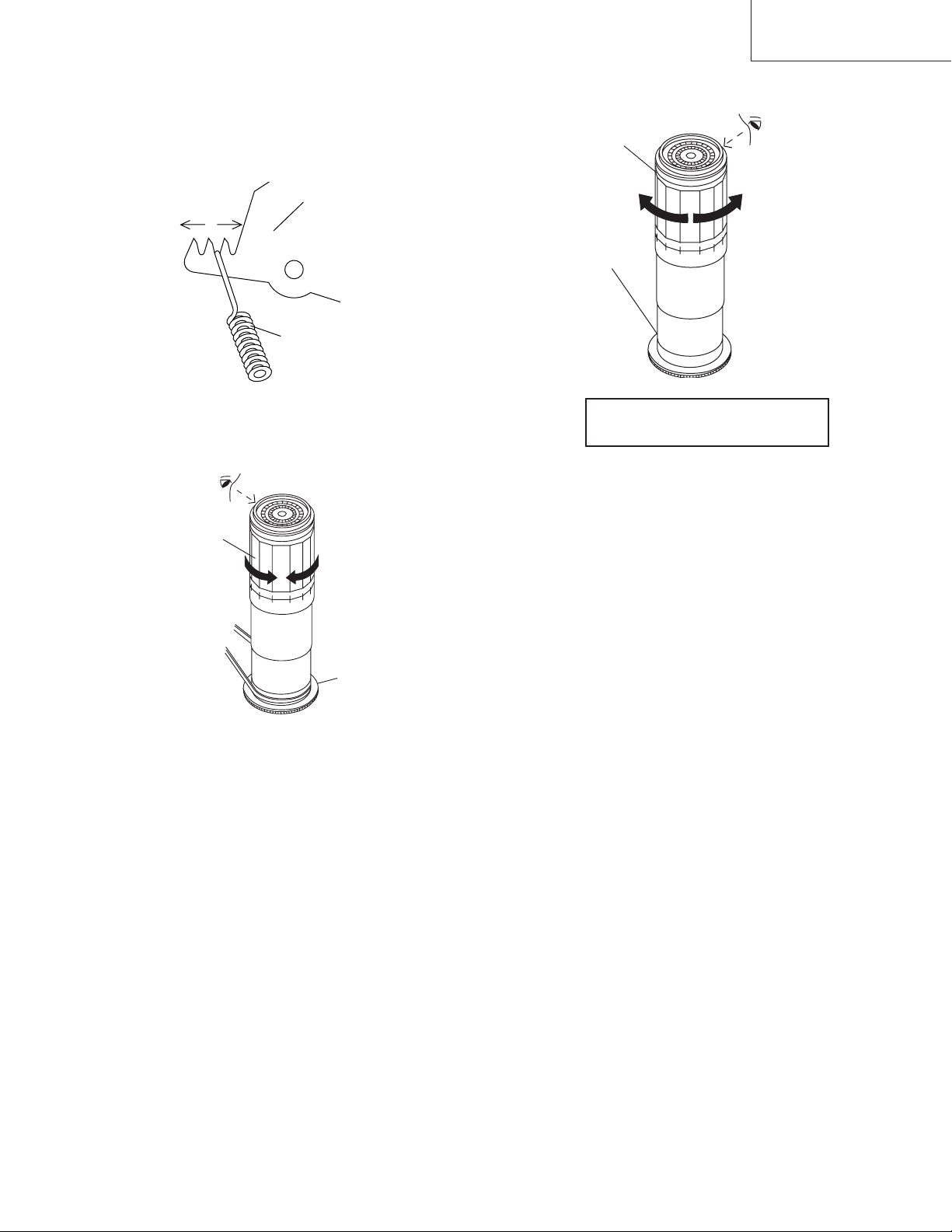
• Adjustment
1. If the indication of torque cassette meter is lower than
the setting, shift the tension spring engagement to the
part A.
2. If the indication of torque cassette meter is higher than
the setting, shift the tension spring engagement to the
part B.
A
B
Tension arm
Tension spring
VC-A10/A10S/A500
VC-A50/A50S/A50SB
VC-A60/A75/A80S
• Checking the brake torque at the take-up side
Torque gauge
CW
Take-up reel
disk
CCW
Figure 4-18.
4-14 CHECKING THE BRAKE TORQUE
• Checking the brake torque at the supply side
Torque gauge
CCW
CCW: 4.41 ± mN⋅m (45 ± gf⋅cm)
CW: 4.12 ± mN⋅m (42 ± gf⋅cm)
+2.0
–1.5
+1.5
–1.2
Figure 4-19.
• Remove the cassette housing control assembly.
• After short-circuiting between TP803 and TP802
provided at main PWB, plug in the power cord.
CW
Supply reel disk
+20
–15
+15
–12
CCW: 4.41 ± mN⋅m (45 ± gf⋅cm)
CW: 4.12 ± mN⋅m (42 ± gf⋅cm)
+2.0
–1.5
+1.5
–1.2
+20
–15
+15
–12
Figure 4-20.
• Remove the cassette housing control assembly.
• After short-circuiting between TP803 and TP802
provided at main PWB, plug in the power cord.
• Setting
1. Switch from the FF mode to the STOP mode.
2. Disconnect the power cord.
3. Set a torque gauge to zero on the scale. Place it on the
take-up reel disk.
4. Please check Idler gear not contact with reel relay gear
(TU side)
• Checking
1. Turn the torque gauge at a rate of about one turn/2 sec
in the CCW direction/CW direction so that the reel disk
and torque gauge pointer rotates at equal speed and
make sure that the value is within the setting (CCW
direction: 4.41 ± 1mN·m (45 ± gf·cm), CW direction:
+1.5
4.12 ± 1.mN·m (42 to gf·cm).
–1.2
+2.0
–1.5
+15
–12
+20
–15
• Setting
1. Set a torque gauge to zero on the scale. Place it on the
supply reel disk.
2. Switch from the FF mode to the STOP mode.
3. Disconnect the power cord.
4. Please check Idler gear not contact with reel relay gear
(SU side)
• Checking
Turn the torque gauge at a rate of about one turn/2 sec
in the CW direction/CCW direction with respect to the
supply reel disk so that the reel disk and torque gauge
pointer rotate at equal speed, and make sure that the
value is within the setting (CW direction: 4.12 ± mN·m
+15
(42 gf·cm); CCW direction: 4.41 mN·m (45 15gf·cm).
–12
+2.0
–1.5
+1.5
–1.2
+20
–15
2. Adjustment of the brake torque at the supply side and the
take-up side
• Unless the supply side brake torque or take-up side
brake torque is within the setting, clean the felt surface
of reel disk (supply, take-up) brake lever, check again
the brake torque.
• If value cannot be set within the setting yet, replace the
main brake ass'y or main brake spring.
17
Page 18
VC-A10/A10S/A500
VC-A50/A50S/A50SB
VC-A60/A75/A80S
4-15 REPLACEMENT OF A/C (AUDIO/CONTROL)
HEAD
1. In eject position unplug the power cord.
• Removal
1. Take out FFC holder from main chassis.
(Push 3 hooking point and pull-up the
holder).
2. Remove the screws 123, Tilt screw.
3. Unsolder the PWB fitted to the A/C head.
Notes:
1. When replacing, never touch the head. If you touched,
clean with the cleaning liquid.
2. When removing the screw 3, take care so that the
spring may out.
3
A/C head screw
Azimuth spring
*Derection designation.
(The bottom part is big.)
2
Azimuth adj. screw
A/C head PWB ass'y
(with A/E)
Tilt screw
A/C head PWB
AC Head
FFC
Holder
3. Align the left end of gear of A/C head arm with the
punched mark of chassis, tentatively tighten the screws
1 so as to ensure smooth motion of A/C head arm.
Tightening torque must be 0.45 ± 0.05N·m (4.5 ±
0.5kgf·cm).
Height screw
1
Left end of A/C head arm gear
Punched line mark on chassis
Figure 4-23.
Note:
1. If the screw 1 is tighten tentatively too loose, the
azimuth and height of A/C head may change when they
are finally tightened. Therefore care must be taken.
2. After completion of A/C head be sure to adjust tape
running. (Execute the running adjustment by the method
described in 4-17.)
Height adj. screw
1
A/C head plate
Height Adj. spring
Figure 4-21.
• Replacement
1. Solder the removed PWB to the new head assembly.
2. Adjust the height from the A/C head arm (lower surface)
to the A/C head plate to 10.8mm with slide calipers. (3
places of azimuth screw section, tilt screw section and A/
C head front section) (See the figure below.)
New A/C head ass'y
A/C head PWB
Solder
A/C head plate
*Fit the groove of FFC to
the boss of the holder.
A/C head FFC
A/C FFC holder
10.8mm
Figure 4-22.
18
Page 19
4-16 A/C HEAD HEIGHT ROUGH ADJUSTMENT
• Setting
Azimuth screw
TiH screw
Height screw
VC-A10/A10S/A500
VC-A50/A50S/A50SB
VC-A60/A75/A80S
4-17 ADJUSTMENT OF TAPE DRIVE TRAIN
1. Tape run rough adjustment
1 Check and adjust the position of the tension pole.
(See 4-12.)
2 Check and adjust the video search rewind back
tension. (See 4-10.)
3 Connect the oscilloscope to the test point for PB ATR
signal output (TP201). Set the synchronism of the
oscilloscope to EXT. The PB ATR signal is to be
triggered by the head switching pulse (TP202).
4 Set the alignment tape (VROCPSV) to play.
Guide roller
Cassette tape
500g
Mechanism chassis
Weight to prevent
float (500g)
Figure 4-24.
1. Set the cassette tape in the unit.
2. Press the PLAY button to put the unit in the playback
mode.
3. Roughly adjust the height of the A/C head by turning the
height screw until the tape is in the position shown
below.
A/C head
Tape
0.3mm
Figure 4-25.
• Adjustment
Adjust the height screw visually so that the control head is
visible 0.3mm below the bottom of the tape.
Cassette Tape
Figure 4-26.
5 Press the tracking button (+), (–) and change the
ATR signal waveform from max to min and from min
to max. At this time make sure that the ATR signal
waveform changes nearly parallel.
6 Unless the ATR signal waveform changes nearly
parallel, adjust the height of supply side and take-up
side guide roller so that the envelope waveform
changes nearly parallel. (For ATR signal adjustment
procedure refer to Figure 4-30.)
7 Turn the tilt screw to remove the tape crease at the
fixing guide flange.
Playback the tape and check for tape crease at the
fixing guide flange.
(1)If there is no tape crease
Turn the tilt screw clockwise so that tape crease
appears once at the flange, and then return the tilt
screw so that the crease disappears.
(2)If there is tape crease
Turn counterclockwise the tilt screw so that the
tape crease disappears.
(Reference) If the tilt screw is turned clockwise
crease appears at the lower flange.
19
Page 20
VC-A10/A10S/A500
VC-A50/A50S/A50SB
VC-A60/A75/A80S
Notes:
1. Previously set the tracking control in the center position,
and adjust the ATR signal waveform to maximum with X
value adjustment nut. Thereby the tape run rough adjustment is facilitated.
2. Especially the outlet side ATR signal waveform must
have higher flatness.
Figure 4-27.
2. Adjustment of A/C head height and azimuth
1 Perform the initial setting of A/C head position by the
method stated in "4-15 Replacement 3".
2 Connect the oscilloscope to the audio output termi-
nal.
3 Using the alignment tape in which 1 kHz linear audio
signal has been recorded, adjust the height screw so
as to get max audio output.
4 Using the alignment tape in which 7 kHz linear audio
signal has been recorded, adjust the azimuth screw
so as to get max audio output.
5 The adjustment of 3 and 4 twice or three times
repeat, and finally adjust 4.
For X value adjustment
Adjust the X value, turning the geartype screwdriver.
Figure 4-28.
3. Tape run adjustment
1 Connect the oscilloscope to PB ATR signal output
test point, set oscilloscope sync to EXT, trigger-input
the PB CHROMA signal (head switching pulse).
2 Rough adjustment of X value
Tentatively fix A/C head arm screws 1 by the method
described in 4-15 "Replacement 3".
Playback the alignment tape (VROCPSV) and
shortcircuit between TP801 and TP802. As a result
the auto-tracking is automatically cancelled, so that
the X value adjustment mode is set.
Move the A/C head with the X value adjustment gear
driver (JiGDRiVER-6) by the method shown in Figure 4-33, and adjust the A/C head so as to get the
maximum ATR signal waveform. (Note: When the A/
C head is adjusted, adjust so that the maximum ATR
signal waveform is obtained nearest the position of
initial setting made in 4-15.)
20
Page 21
3 Next, press the tracking button (+), (–) and change
the ATR signal waveform from max to min and from
min to max. At this time adjust the height of supply
and take-up side guide roller with the adjustment
driver (JiGDRiVERH-4) so that the ATR signal waveform changes nearly parallel.
4 If the tape is lifted or sunk from the helical lead
surface, the PB ATR signal waveform appears as
shown in Figure 4-30.
5 Press the tracking button (+), (–) and make sure that
the ATR signal waveform changes nearly parallel.
6 Finally, check tape crease near the reverse guide. If
tape crease is found, adjust tilt screw 45˚ counter
clockwise. Small tape crcase will appear at retain
guide after this adjustment finished.
Supply side
Take-up side Supply side Take-up side
VC-A10/A10S/A500
VC-A50/A50S/A50SB
VC-A60/A75/A80S
PB ATR
Signal
Head switching pulse
Figure 4-29.
4. A/C head X value adjustment
1 Fix A/C head arm screws 1 by the method described
in 4-15 "Replacement 3".
2 Playback the alignment tape (VROCPSV), and
shortcircuit between TP801 and TP802. As a result
the auto-tracking is automatically cancelled, so that
the X value adjustment mode is set.
When the tape is below the helical lead.When the tape is above the helical lead.
Adjustment
Supply side guide roller
rotated in clockwise
direction (lowers guide
roller) to flatten
ATR signal.
Take-up side guide roller
rotated in clockwise
direction (lowers guide
roller) to flatten
ATR signal.
Figure 4-30.
3 Move the A/C head with the X value adjustment gear
driver by the method shown in Figure 4-33, and
adjust the A/C head so as to get the maximum ATR
signal waveform. (Note: At this time adjust so as to
get the maximum ATR signal waveform nearest the
A/C head position which has been set in case of X
value rough adjustment as stated in 4-17, 3- 2.)
4 Adjust the playback switching point (Refer to the
electric adjustment method.)
5 Playback the self-picture-recorded tape, and check
the flatness of ATR signal waveform and sound.
Supply side guide roller
rotated in counterclockwise direction (raises
guide roller) to make the
tape float above the helical
lead. The supply
side guide roller is then
rotated in the clockwise
direction to flatten the
ATR signal.
Take-up side guide roller
rotated in counterclockwise direction (raises
guide roller) to make the
tape float above the
helical lead. The take-up
side guide roller is then
rotated in the clockwise
direction to flatten the
ATR signal.
Notes:
When the A/C head X value adjustment is performed, be
sure to perform at first X value rough adjustment (refer to 4-
17, 3-2).
1
21
Figure 4-31.
Page 22
VC-A10/A10S/A500
VC-A50/A50S/A50SB
VC-A60/A75/A80S
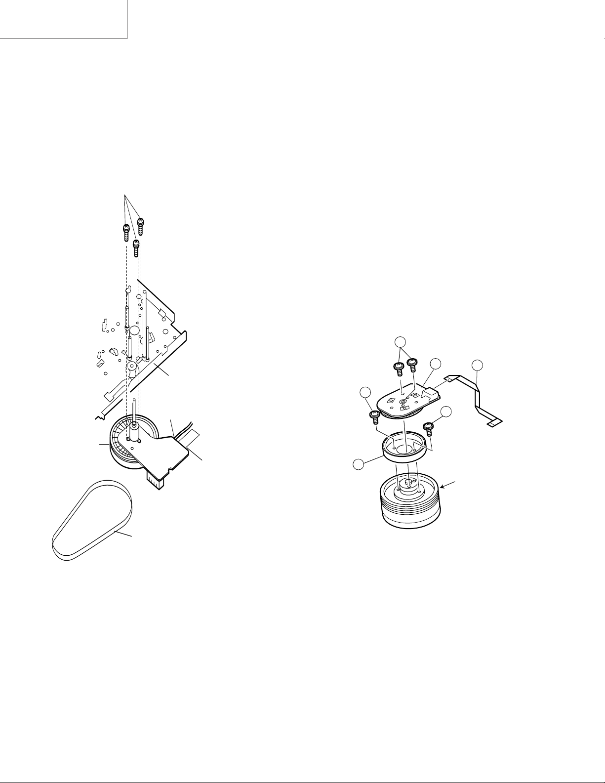
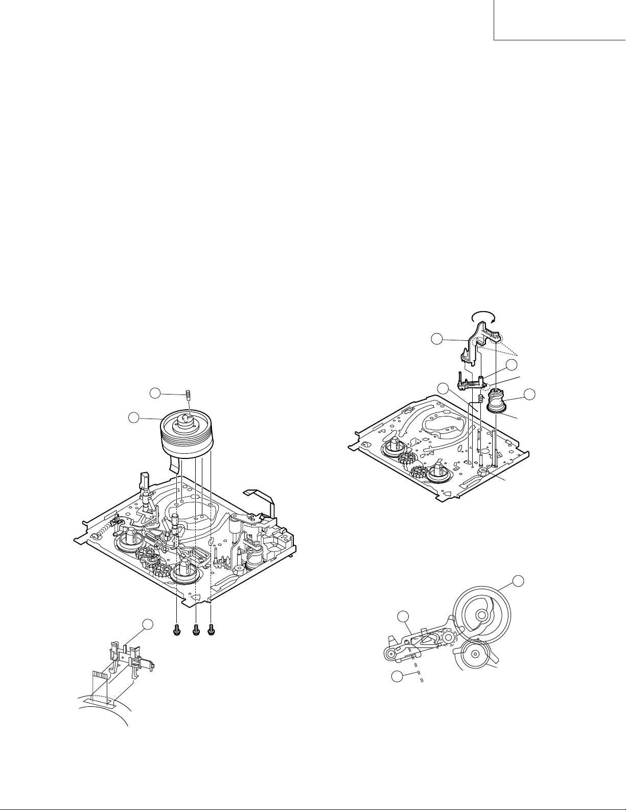
4-18 REPLACEMENT OF THE CAPSTAN D.D.
(DIRECT DRIVE) MOTOR
• Remove the mechanism from the set.
4-19 REPLACEMENT OF DRUM D.D. MOTOR
1. Set the ejection mode.
2. Withdraw the main power plug from the socket.
• Removal (Follow the order of indicated numbers.)
1. Unsolder loading motor wire and drum FFC (except for
VC-A50S).
2. Remove the reel belt 1.
3. Remove the three screws 2.
• Reassembly
2
Mainchassis
• Removal (Perform in numerical order.)
1. Disconnect the FFC cable 1.
2. Unscrew the D.D. stator assembly fixing screws 2.
3. Take out the D.D. stator assembly 3.
4. Unscrew the D.D. rotor assembly fixing screws 4.
5. Take out the D.D. rotor assembly 5.
Notes:
1. In removing the D.D. stator assembly, part of the drum
earth spring pops out of the pre-load collar.
Be careful not to lose it.
2. Install, so that the D.D. rotor ass'y and upper drum ass'y
mounting direction check holes align.
(Align the upper drum dent with the rotor hole.)
3. Be careful not to damage the upper drum or the video
head.
4. Protect the hole elements from shock due to contact with
D.D. stator or D.D. rotor ass'y.
5. After installation adjust the playback switching point for
adjustment of servo circuit.
2
D.D.stator ass'y
2
4
1
Solder loading motor wire
Capstan
D.D. motor
Solder drum FFC
1
Reel belt
Figure 4-32.
1. Taking care so that the capstan shaft does not contact
the mechanism chassis, set its position on the mechanism chassis, and then install with the three screws.
2. Install the reel belt.
3. Solder loading motor wire and insert drum FFC (except
for VC-A50S).
Notes:
1. After installing the capstan D.D. motor, be sure to rotate
the capstan D.D. motor and check the movement.
2. Set the tape, and check for the tape crease near the
reverse guide in the playback mode. Adjust the A/C
head and azimuth as stated in 4-17 item 2.
4
5
Figure 4-33.
D.D. rotor ass'y
Upper drum
FFC
22
Page 23
4-20 REPLACING THE UPPER AND LOWER
DRUM ASSEMBLY
• Replacement (Perform in the numerical order)
1 Remove the motor as stated in 4-19 D.D. motor replace-
ment.
2 Remove the drum earth brush ass’y 2.
3 Remove the upper and lower drum assembly from main
chassis 1.
4 Remove the drum FFC holder 3.
VC-A10/A10S/A500
VC-A50/A50S/A50SB
VC-A60/A75/A80S
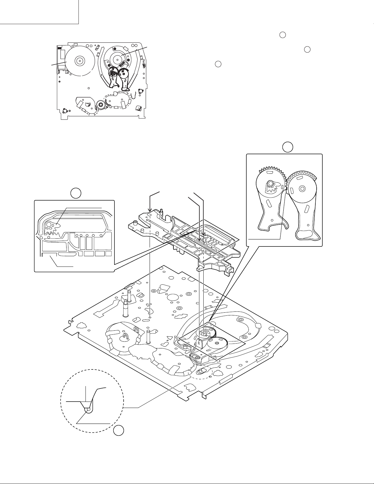
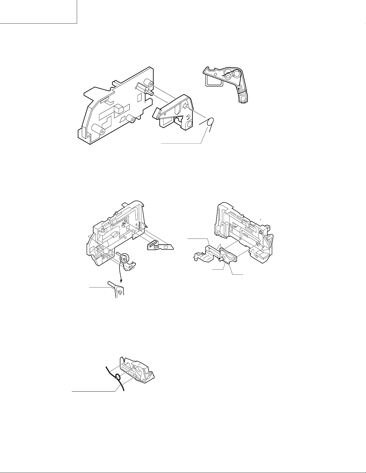
4-21 ASSEMBLING OF PHASE MATCHING
MECHANISM COMPONENTS
• Assemble the phase matching mechanism components in the following order.
1. Assemble the reverse guide lever and pinch drive cam.
2. Mounting the shifter (on the back of the mechanism
chassis).
3. Mounting the master cam (on the back of the mechanism chassis).
4. Assemble synchro gear.
5. Assemble the loading motor parts.
[Cares when replacing the drum]
1. Be careful so that the drum earth brush is not lost.
2. Do not touch directly the drum surface.
3. Fit gently the screwdriver to the screws.
4. Since the drum assembly is an extremely precise assembly, it must be handled with utmost care.
5. Make sure that the drum surface is free from dust, dirt
and foreign substances.
6. After replacing the drum be sure to perform the tape
running adjustment.
After that, perform also the electrical adjustment.
• Playback switching point adjustment
• X-position adjustment and check
• Standard and x-3 slow tracking adjustment
7. After replacing the drum clean the drum.
2
1
• PINCH DRIVE CAM AND REVERSE GUIDE
LEVER ASSEMBLING METHOD.
(Place the following parts in position in numerical order.)
(1)Pinch drive cam 1
(2)Reverse guide spring 2
(3)Reverse guide lever ass’y 3
(4)Open guide 4
4
2
Insert it into the
groove of the shaft
3
Don't run up
on the spring
1
Dot A
Dot B
Lower drum bottom side
3
Figure 4-34.
Figure 4-35.
1
3
Synchro gear
2
From Top View
23
Page 24
VC-A10/A10S/A500
VC-A50/A50S/A50SB
VC-A60/A75/A80S
4-22 INSTALLING THE SHIFTER
Capstan D.D.
motor
(Bottom side of mechanism chassis)
Drum
1. Make sure that the loading arm T and S are at the PhaseMatching point as shown below .
a
2. Fix the shifter position setting part to the roading arm T
position setting part as shown in figure .
b
3. Make sure tension arm not run on the shifter as shown
in figure .
c
Figure 4-36.
b
Loading arm (T)
Shifter
Insert point
Loading arm (T)
Phase matting
a
Loading arm (S)
*Not run on the
sifter.
Sifter
Tension arm
c
Figure 4-37.
24
Page 25
4-23 INSTALLING THE MASTER CAM (AT
REAR SIDE OF MECHANISM CHASSIS)
1. Make sure beforehand that the shifter is at initial position. (Right side from bottom view)
2. Place the master cam in the position as shown below.
3. Fix the E ring.
VC-A10/A10S/A500
VC-A50/A50S/A50SB
VC-A60/A75/A80S
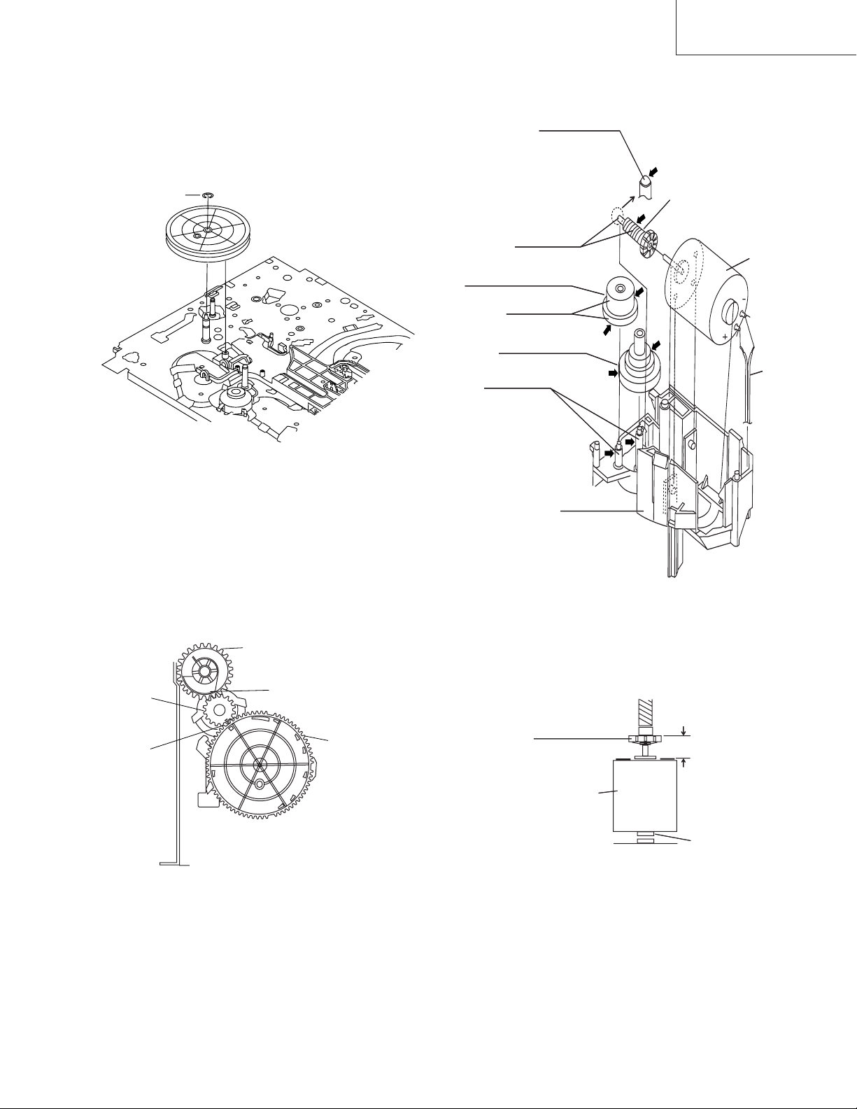
4-24 REPLACEMENT OF LOADING MOTOR
• Removal
Apply grease
*Apply grease to
the tip as well.
E-ring
Figure 4-38-1.
4. Adjust the master cam and pinch drive cam, fix the
synchro gear in correct position.
Note:
See the figure below for the phase matching between the
master cam synchro gear and pinch drive cam.
Apply grease
Leading connect gear.
Apply grease
Worm wheel gear.
Apply grease
L-M-Block.
Figure 4-39.
Worm gear
Red
Loading
motor.
Wire
+ : Red
- : White
Insert
Synchro
gear
Phase
matching
Pinch Drive Cam
Hole of Pinch Drive Cam
Figure 4-38-2.
Master Cam
• Replacement
Remove the loading motor, and install the replacement
loading motor as shown below.
Worm gear
Loading
motor
To press the motor in, first
receive it by portion A.
+0
6.95 mm
-0.15
A part
Figure 4-40.
The loading motor pressing-in must be less than 196N (20
kgf).
Adjust the distance between motor and pulley to 6.95
+0. 2
mm.
–0.15
25
Page 26
VC-A10/A10S/A500
VC-A50/A50S/A50SB
VC-A60/A75/A80S
4-25 ASSEMBLY OF CASSETTE HOUSING
1. Proof lever Proof lever spring and Holder R
*Proof lever spring fixing direction designated.
2. 0pen lever, Sensor Plate and Frame R
MSPRD0215AJFJ
Figure 4-41.
Take care that
not to damage
this parts.
3. Spring to Drive Arm R
MSPRD0212AJFJ
out side
top
out side
inside
bottom
Figure 4-42.
Figure 4-43.
26
Page 27

4 Frame R, Frame L, Drive Arm R, Drive Arm L, Upper Plate.
LANGF9661AJFW
VC-A10/A10S/A500
VC-A50/A50S/A50SB
VC-A60/A75/A80S
Top surface should be free from scratches or soil.
When assemble drive lever to frame R,
make sure the hole synchronize.
Figure 4-44.
27
Page 28

VC-A10/A10S/A500
VC-A50/A50S/A50SB
VC-A60/A75/A80S
5. ELECTRICAL ADJUSTMENT
Notes:
• Before the adjustment:
Electrical adjustments discussed here are often required after replacement of electronic components and mechanical
parts such as video heads.
Check that the mechanism and all electric components are in good working condition prior to the adjustments,
otherwise adjustments can not be completed.
• Instruments required:
Colour TV monitor Dual-trace oscilloscope
Audio signal generator AC milli-voltmeter
Blank video cassette tape Alignment tape(VROCPSV)
Screwdriver for adjustment
Colour bar singnal generator
• Location of controls and test points
T601
TP201
TP801
Figure 5-1.
28
Page 29

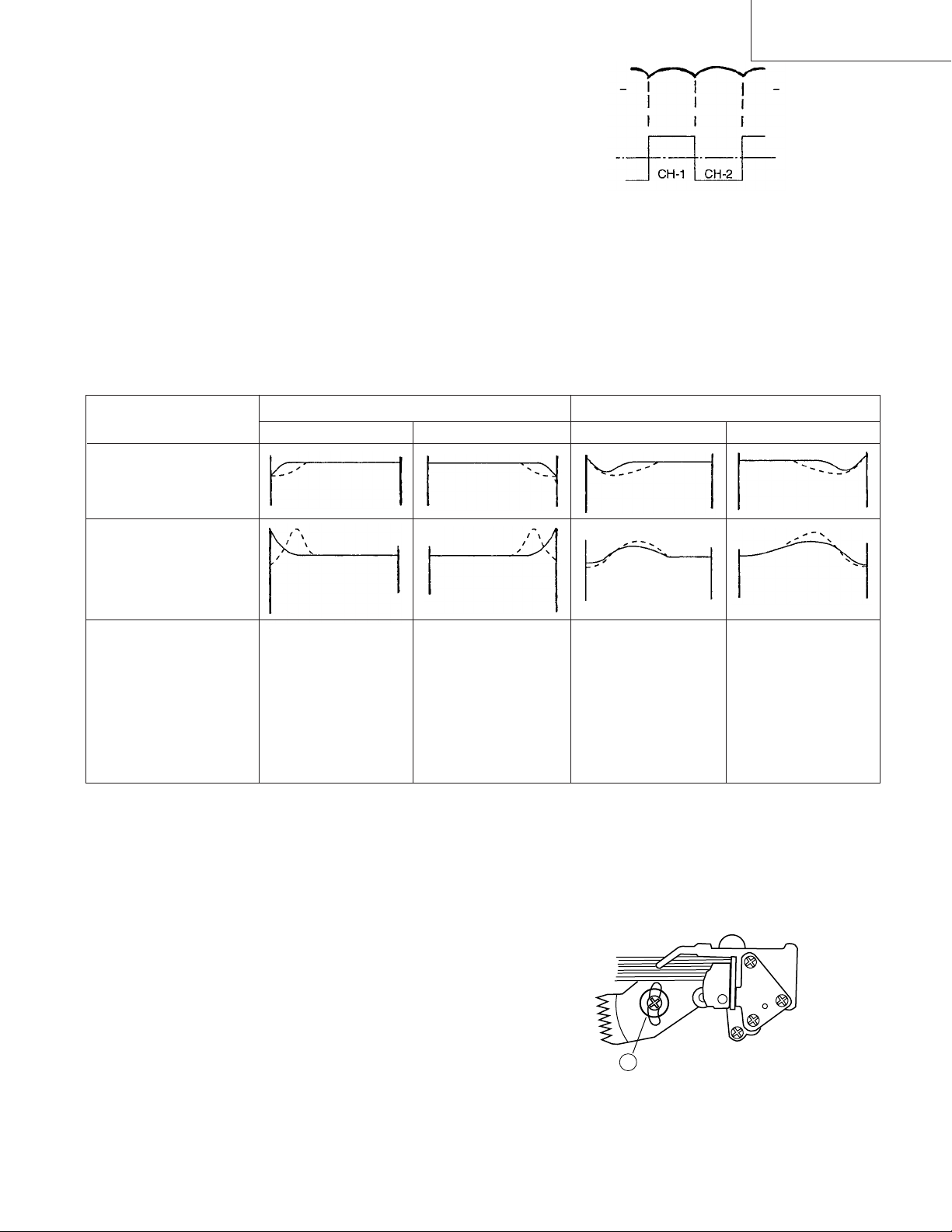
SERVO CIRCUIT ADJUSTMENT
ADJUSTMENT OF HEAD SWITCHING POINT
Measuring
instrument
Mode
Cassette
Test point Pin(2) of P201 (H.SW.P.) to CH-1,
Specification 6.5 ± 0.5H (lines)
1. Remove the front panel and play the alignment tape.
2. Get TP801 short circuited or press press "TEST"key(47H)
at Universal remote control to call the test mode.
(LCD will blinking as tracking goes to center)
3. Press "PLAY" key.
Auto PG Mode will be ON and playback mark " > "
blinking.
4. Press "STOP" key
" > " blinking stops and auto adjustment finished.
5. Check that V-Sync is 6.5±0.5H and the waveform is as
shown in Figure 5-2.
Note:
Formanual PG Adjustment,press FF or REW key at
the Test Mode to set the tracking in center.
Dual-trace oscilloscope
Colour TV monitor
Playback
Alignment tape
Head Tape
2 CBZF
2LP BBZG
4 CBZF
4HiFi CBZF
VIDEO OUT jack to CH-2
(CH-1 trigger slope switch at (+),
Internal trigger at CH-1 side.)
VC-A10/A10S/A500
VC-A50/A50S/A50SB
VC-A60/A75/A80S
ADJUSTMENT OF PAL SYSTEM FV (False
Vertical Sync) OF STILL PICTURE
Measuring
instrument
Mode
Cassette
Control Tracking control buttons (+) or (-)
Specification No vertical jitter of picture
1. Play a self-recorded tape.
2. Press the PAUSE/STILL button to freeze the picture.
3. Adjust (+) or (-) TRACKING buttons on the remote
control so that the vertical jitter of the picture is minimized.
Note:
1 Self-recorded tape is a cassette which program was
recorded by the unit being adjusted.
2 The FV goes back to the it's initial state when the unit
is put into the system controller reset mode due to
power failure,etc.
In this case, preset the FV once again.
Colour TV monitor
Playback still
Self-recorded tape (SP/LP,EP mode)
(See Note below 1)
Y/C CIRCUIT ADJUSTMENT
CHECKING OF VIDEO E-E LEVEL
Measuring
instrument
Mode
Input signal
Oscilloscope
E-E or Record
EIA colour bar (1.0Vp-p)
CH-2
Video signal
CH-1
Head Switching Pulse
6.5 ± 0.5H
Figure 5-2.
V: 2V/div
Test point VIDEO OUT jack
Specification 1.0 ± 0.2 Vp-p
1. Connect a 75 ohm terminating resistor to the VIDEO
OUT jack and connect an oscilloscope across this
termi-nating resistor.
(See Note below.)
2. Feed a colour bar signal to the VIDEO IN jack.
3. Make sure that the E-E signal amplitude is 1.0Vp-p as
shown in Figure 5-3.
1.0 Vp-p
Note:
If the 75 ohm terminating resistor is missing, the signal
amplitude will be doubled.
29
Figure 5-3.
Page 30

VC-A10/A10S/A500
VC-A50/A50S/A50SB
VC-A60/A75/A80S
CHECKING OF PLAYBACK LEVEL
Measuring
instrument
Mode
Cassette
Specification 1.0 ± 0.2 Vp-p
1. Be sure that E-E level has been correctly specificed.
2. Connect a 75 ohm terminating resistor to the VIDEO OUT
jack and connect an oscilloscope across this terminating
resistor.(See Note below 1 )
3. Play a self-recorded tape.
4. Make sure that the output signal amplitude is
1.0Vp-p as shown in Figure 5-4.
Note:
1 If the 75 ohm terminating resistor is missing, the signal
amplitude will be doubled.
2 Self-recorded tape is a tape which program was re-
corded by the unit being adjusted.
Oscilloscope
Record/Playback
Self-recorded tape
(See Note below 1)
CHECKING OF AUDIO RECORD LEVEL
Measuring
instrument
Mode
Input signal
Test point AUDIO OUT jack
Specification –8.0 ± 3 dBs
1. Connect an AC milli-voltmeter to the AUDIO OUT jack.
2. Feed the audio signal shown in table to the AUDIO IN
jack.
3. Make the self-recording and playback of the signal.
4. Make sure that the output level is value shown in table.
AC milli-voltmeter
Record/playback
1kHz, –8.0 dBs
CHECKING OF ERASE VOLTAGE AND OSCILLATION FREQUENCY
Measuring
instrument
Mode
Test point
Oscilloscope
Record
Full erase head
1.0 Vp-p
Figure 5-4.
AUDIO CIRCUIT ADJUSTMENT
CHECKING OF E-E LEVEL
Measuring
instrument
Mode
Input signal
Test point AUDIO OUT jack
Specification –8.0 ± 3 dBs
1. Connect an AC milli-voltmeter to the AUDIO OUT jack.
2. Feed the audio signal shown in table to the AUDIO IN
jack.
3. Put the unit in E-E or recording mode.
4. Make sure that the output level is value shown in table.
AC milli-voltmeter
E-E/Record
1kHz, –8.0 dBs (at RCA type jack)
Control T601
Specification 70 ± 5kHz, 40Vp-p or greater
1. Connect an oscilloscope across the full erase head.
2. Put the unit in recording mode.
3. Make sure the erase voltage across the full erase head is
approx. 40Vp-p or more and frequency is 70 ± 5kHz.
30
Page 31

VC-A10/A10S/A500
Loading motor turns in reverse
direction and master cam
clockwise.
CASSETTE INSERTION STOP
Cassette
inserting
Full-
loading
YES
YES
YES
NO
NO
Loading motor starts in forward
direction and master cam counter
clockwise.
Does mechanism position sw.
come off within 2.5 sec.?
Are start/end sensors at low level
before cassette insertion ?
Insert cassette.
Drum motor starts.
Tape loading.
Pinch roller comes into contact.
Mode switch is at PB position.
Loading motor stop.
NO
Unloading
Is drum FG pulse outputted ?
End
End
Cassette is ejected and loading
motor stops.
Start sensor close.
(Cassette is judged
caught halfway.)
(Cassette LED or some other part
is judged defective.)
1
0
1
1
1
1
1
1
1
1
1
0
1
0
1
0
0
0
1
0
1
0
0
0
1
0
0
0
0
0
1
0
0
0
1
0
1
0
0
0
1
0
S Sensor
Open
Close
111000000
011110110
CS/EJ
ULD
PU1
PU2
VSRPBSLOWFFSTOP
Code 1
Code 2
S Sensor
EJ UL PU PU2 VSR PB SLW FF STP
011
011
000
001
0
0
1 or 0
Code 1
(Mode SW/outside)
Code 2
(Mode SW/inside)
Mecha Mode
600 120 180
240
300 360
Mecha Mode
Mode check
Cam mark
Code 1
(Mode SW/outside)
Code 2
(Mode SW/inside)
CS/EJ UL PU1 PU2 VSR
PB
STILL
SLOW
REW
FF
STOP
VC-A50/A50S/A50SB
VC-A60/A75/A80S
MECHANISM OPERATION FLOWCHART
* This flowchart describes the outline of the mechanism’s operation, but does not give its details.
6. MECHANISM OPERATION FLOWCHART AND TROUBLESHOOTING GUIDE
31
Page 32

VC-A10/A10S/A500
STOP REC/PLAY
PLAY STILL
PLAY VSR
VSR PLAY
Capstan motor turns
counterclockwise.
Is take-up reel sensor signal
outputted ?
End
Press REC/PLAY key.
Picture appears.
Unloading
Set capstan motor to search
speed.
End
Press FF key.
PLAY VSF
REC/PLAY STOP
Capstan motor turns in
reverse direction.
Loading motor turns in
forward direction and master
cam CCW.
Slow brake comes into
contact with capstan motor.
Slow brake
pressing
Mode switch is at STILL
position.
End
Capstan motor stops.
Press STOP key.
Loading motor stops.
End
Stop capstan motor.
NO
YES
Press STILL key.
Pinch
roller
releasing
Idler
swinging
Pinch
roller
pressing
Loading motor turns reverse
direction and master cam
clockwise.
Turn capstan motor in
reverse direction.
Turn loading motor forward
direction.
Mode switch is at VSR
position.
Set capstan motor to search
speed.
Is take-up reel sensor signal
outputted ?
Press REW key.
Release pinch roller.
Mode switch is at PU2 position.
Mode switch is at PU1 position.
Stop loading motor.
Press pinch roller.
Loading motor turns reverse
direction
Release the supply main
brake.
Stop loading motor.
End
Unloading
Mode switch is at PB position.
End
Press PLAY Key.
Loading motor turns forward
direction and master cam
CCW.
Capstan motor turns
counterclockwise. PB speed.
NO
YES
VC-A50/A50S/A50SB
VC-A60/A75/A80S
32
Page 33

VC-A10/A10S/A500
STOP FF/REW
STOP CASSETTE EJECT
FF/REW STOP
NO
NO
FF/REW
operation
Brake
function
Turn capstan motor in
normal or reverse direction,
after the remaining tape has
been detected.
Loading motor turns forward
direction.
Mode switch is at Stop
position.
End
Press STOP key.
Press FF/REW key.
Stop capstan motor.
Mode SW is at FF/REW
position.
Loading motor rotate forward.
Loading Motor stop rotate.
Mode SW at PB position.
Loading motor reverse direction.
Loading Motor stop rotate.
Loading motor stops.
End
Loading motor turns in reverse direction and master cam
clockwise.
4 supply reel pulses
outputted ?
Does the take-up
reel pulse output
two edges ?
Capstan motor turns
clockwise.
Loading motor turns
reverse direction.
Mode switch is at
Eject position.
Loading motor
stops.
Capstan motor
stops.
Press EJECT key.
Tape
unloading
Cassette
eject
End
Capstan motor turns
clockwise.
Capstan motor turns
counterclockwise in about
2 seconds.
Stop loading motor.
Capstan motor turns in reverse direction.
Mode switch is at UL position.
YES
YES
VC-A50/A50S/A50SB
VC-A60/A75/A80S
33
Page 34

VC-A10/A10S/A500
MECHANISM TROUBLESHOOTING
1. FF/REW FAILURE (NO TAPE WINDING)
Press FF key.
NO
NO
NO
NO NO NO
NO
NO
YES
YES
YES
YES
YES
YES
YES YES
Is master cam at
FF position ?
Does loading
motor operate ?
Modes changing
smoothly through
mode switch ?
Loading motor
control system
in trouble.
Are Vco 24V and
Vcc 5V applied ?
Replace the
capstan motor.
Replace the idler
ass’y.
Replace the reel
sensor.
Is voltage applied
to loading motor ?
Loading motor is
damaged. Replace
it.
Voltage supply
system in trouble.
Mode SW in
trouble or master
cam malpositioned.
Voltage supply
system in trouble.
Does capstan
motor turn in FF (or
REW) direction ?
Are idler wheel
ass’y and reel disk
in mesh ?
Is the pulse
outputted from reel
sensor ?
The cassette tape
is presumably
damaged.
2. REC/PLAY FAILURE (MODE RELEASE)
NO
NO
NO
NO NO NO
NO
YES
YES
YES
YES
YES
YES
YES YES
Is the master cam
at PB position ?
Does loading
motor operate ?
Modes changing
smoothly through
mode switch ?
Loading motor
control system
in trouble.
Are Vco 24V and
Vcc 5V applied ?
Replace the
capstan motor.
Replace the idler
ass’y.
Replace the reel
sensor.
Is voltage applied
to loading motor ?
Loading motor is
damaged. Replace
it.
Voltage supply
system in trouble.
Voltage supply
system in trouble.
Does capstan
motor turn ?
Are idler wheel
ass'y and reel disk
in mesh ?
Is the pulse
outputted from reel
sensor ?
Check main PWB.
VC-A50/A50S/A50SB
VC-A60/A75/A80S
34
Page 35

VC-A10/A10S/A500
Replace loading motor block.
3. WINDING FAILURE AT VSR 4. UNUSUAL SOUND IN EACH MODE
Is Playback
function normal ?
Master cam
shifting to VSR
position ?
Go to 2. REC/
PLAY FAILURE
routine.
Replace idler
gear ass’y.
Replace limiter
pulley ass’y.
Replace reel
sensor.
Go to 2. REC/
PLAY FAILURE
routine.
Are idler wheel
ass’y and supply
reel disk in mesh ?
Is supply reel disk
winding torque
normal ?
Is pulse outputted
from reel sensor ?
Check main PWB.
YES
YES
YES
YES
YES
NO
NO
NO
NO
NO
YES
YES
NO
NO
YES
Press REW key.
4-i) Unusual sound in cassette
insertion and ejection mode
Is unusal sound heard during
cassette control running ?
Unusual sound heard with pinch
roller lever going up or down ?
Is unusual sound heard during
loading/unloading ?
Check pinch drive cam, pinch roller ass'y
and reverse guide for their actions.
Replace damaged one with new one.
Replace cassette control ass’y.
VC-A50/A50S/A50SB
VC-A60/A75/A80S
35
Page 36

VC-A10/A10S/A500
YES
YES
NO
NO
NO
NO
YES
YES
Replace capstan motor.
4-ii) Unusual sound in FF/REW mode
Is reel disk height as specified ?
Thrust gap found at reel disk ?
Drive system out of contact with any
part on main PWB ?
Turn capstan motor by hand.
Unusual sound heard ?
Check drive system’s gears for
damage. Replace damaged gear
with new one.
• Reel disk
• Limiter pulley ass’y
• Idler gear ass’y
Check reel disk and main chassis.
And replace defective parts.
Adjust reel disk height.
Rearrange the parts on main PWB.
VC-A50/A50S/A50SB
VC-A60/A75/A80S
36
Page 37

VC-A10/A10S/A500
FLOW CHART NO.1 POWER TROUBLESHOOTING(1)
No power.
The fuse blows out even when it is
replaced with new one.
See FLOW CHART NO.2
POWER TROUBLESHOOTING (2)
<In case of Fuse (F901) blown out.>
YES
YES
YES
NO
NO
NO
NO
Is the fuse good?
Is the normal state restored when
once unplugged power cord is
plugged again after several
seconds?
Check for leak or short-circuiting
of primary circuit part
(D901~906, Q901~903, T901,
C906, L901, D912 etc.), replace
defective parts.
Are AT 5V voltage line normal?
Are AT 5V and AT 12V lines normally?
Check each rectifier circuits and
short-circuit of secondary circuit.
FLOW CHART NO.2 POWER TROUBLESHOOTING(2)
In case of Fuse (F901) blown out.
Check for leak or short-circuiting of
primary circuit part
(D901~906, Q901~903, T901,
C906, L901, D912 etc.), replace
defective parts.
Check for short-circuit of rectifying
diode and circuit in each rectifying
circuit of secondary circuit.
(D934, D933, D932, D931)
FLOW CHART NO.3 POWER TROUBLESHOOTING(3)
In case of abnormal noise (sound).
Check for short circuit of rectifying diode of each rectifying circuit of secondary circuit
and check for shunt regulator circuit. (D934, D933, IC903, C9335~9336)
FLOW CHART NO.4 POWER TROUBLESHOOTING(4)
In case of output voltage at low level.
Check whether the secondary side
photocoupler circuit operates
normally.
Check the circuit and replace
defective parts. (IC901, IC903, etc.)
NO
YES
Check whether the primary side
photocoupler output control
function normally.
Check the circuit and replace
defective parts. (IC901, IC903, Q902,
T901, etc.)
NO
YES
Replace IC901.
FLOW CHART NO.5 SYSTEM CONTROL TROUBLESHOOTING(1)
No power is turned on.
Does power control (H) signal at
pin(76) of IC701 change from "L" to
"H" level?
Check IC701.
Does the base of Q967 change from
"L" to "H" level?
Check lines between the Q967 and
all the way up to IC701.
Is about 4.4V applied at the base
of Q968?
Check Q967, Q968, and Q961.
Is 12V at the collector of Q968?
Check line between Q968 and
all the way up to AT 12V line.
Is 12V at the emitter of Q968?
Check peripheral circuits for poor
soldering.
Check AT 12V line.
YES
YES
YES
YES
YES
NO
NO
NO
NO
NO
VC-A50/A50S/A50SB
VC-A60/A75/A80S
7. TROUBLESHOOTING
37
Page 38

VC-A10/A10S/A500
FLOW CHART NO.7 KEY CONTROL TROUBLESHOOTING(2)
Does the key switch make good
contact, when the cassette tape is
inserted?
Check switch contact.
Is there the function control voltage
inputted at the pins(88) and (89) of
IC701, when the keys are activated?
Replace IC701.
Check peripheral circuit of pins(88)
and (89) of IC701, and the function
keys.
YES
NO
NO
YES
Key-in input is not received
<Except for jog shuttle mode.>
(TP802)
(TP801)
(S882)
(S881)
(S804)
(S803)
(S802)
(S801)
4.9
3.8
3.1
2.5
1.9
1.2
0.6
0V
CASSETTE
TEST
STOP
PLAY
CH-
MENU
EJECT
POWER
(S886)
(S884)
(S808)
(S807)
(S806)
(S805)
FF
REW
REC/RENTAL
P/STILL
CH+
SET
Key0 Key1
FLOW CHART NO.8 INFRARED R/C TROUBLESHOOTING
No operation is possible from the infrared remote control.
Does the infrared remote control
function?
Replace infrared remote control as
required.
Is the supply voltage of 5V fed to C805
of (+) side?
Check AT 5V and GND lines.
Is "L" pulse sent out from pin(1) of the
receiver when the infrared remote
control is activated?
Replace receiver.
Check between at pin(1) of receiver and
all the way up through to pin (4) of IC701.
Replace IC701.
YES
NO
YES
NO
NO
NO
YES
Is the cassette housing distorted?
Fix or replace the cassette housing.
NO
YES
YES
YES
YES
NO
YES
NO
NO
YES
NO
YES
FLOW CHART NO.9 CASSETTE CONTROL TROUBLESHOOTING(1)
A cassette tape is not take in.
NO
NO
Check start sensor cover.
Check line between start sensor and
pin (67) of IC701
Check line between pin (72) of IC701
and pin(31) of IC706.
Is the supply voltage of 12V fed to pin
(13) of IC706?
Check M 12V lines.
Check IC706.
Check line between IC706 and loading
motor.
Replace loading motor.
Is the specified voltage applied at the
loading motor terminal when the
cassette tape is inserted?
Does pin(31) of IC706 change to about
10V when the cassette tape in inserted?
Does pin(11) of IC706 go to a "H" level
when the cassette tape is inserted?
Does pin(67) of IC701 change from"H"
to "L" level when the cassette tape is
inserted?
Does the start sensor cover go to open
when the cassette tape is inserted?
YES
YES
YES
NO
NO
NO
FLOW CHART NO.6 POWER TROUBLESHOOTING(6)
In case of output voltage at low level.
Check peripheral circuits IC901, IC903,
C9336, R932, R935, R930 and R931.
The result of IC901, IC903, C9336, R932, R935,
R930 and R931. Replace where necessary.
Check IC903 and peripheral circuits
of IC901.
Replace IC901.
Check short-circuit or leak of T901.
Replace T901.
Check primary circuit and peripheral
circuit of Q901.
VC-A50/A50S/A50SB
VC-A60/A75/A80S
38
Page 39

VC-A10/A10S/A500
NO
NO
NO
FLOW CHART NO.10 CASSETTE CONTROL TROUBLESHOOTING(2)
A cassette tape is taken in, but ejected at once.
Does the start sensor pulse at pin (67)
of IC701 change from "L" to "H" level
when the cassette tape is loaded?
Check line between start sensor and pin
(67) of IC701.
Does the end sensor pulse at pin (66)
of IC701 change from "L" to "H" level
when the cassette tape is loaded?
Check line between end sensor and pin
(66) of IC701.
Does the master cam mode shifter
operate normally when the cassette
tape is loaded?
Check line between cam switch and
IC701.
Replace IC701.
YES
YES
YES
FLOW CHART NO.11 LOADING MOTOR AND EJECT TROUBLESHOOTING
The cassette tape fails to come out.
Does the capstan motor start when the
EJECT button is pressed?
See FLOW CHART NO.12. CAPSTAN
MOTOR TROUBLESHOOTING
Does the take-up reel disk turn when the
capstan motor is running?
Check line between take-up reel
sensor and pin(2) of IC701.
Is a "H" level applied at pin(31) of IC706
when a reel pulse has been inputted?
Check line between pin(72) of IC701
and pin(31) of IC706.
Is the supply voltage of 12V fed to
pin(13) of IC706?
Is the voltage about 10V sent out from
pin(14) of IC706?
Check IC706.
Is the specified voltage applied at the
loading motor terminal?
Check line between IC706 and
loading motor.
Does the loading motor run? Replace loading motor.
Replace cassette cam, gear, etc.
YES
YES
YES
Check M 12V lines.
NO
YES
NO
YES
YES
YES
NO
NO
NO
NO
NO
FLOW CHART NO.12 CAPSTAN MOTOR TROUBLESHOOTING
The capstan motor fails to run.
Is the voltage more than about 2.6V
DC given out of pin(24) of IC701?
Check IC701.
NO
NO
NO
NO
NO
YES
YES
YES
YES
Is the supply voltage of 5V fed to
pin(3) (sankyo IC) or pin(7) (kuma-
gaya IC) of AC connector?
Check PC 5V line.
Is the voltage more than 2.6V DC
sent in pin(9) (sankyo IC) of AC
connector or pin(35) (kuma-gaya
IC) of IC706?
Check line between pin(9) (sankyo IC)
of AC connector or pin(35) (kumaga-
ya IC) of IC706 and pin(29) of IC706.
Is the voltage of pin(5) (sankyo IC)
of AC connector or pin(40) (kuma-
gaya IC) of IC706 is 1.6~2.7V?
Check line between the pin(71) of
IC701 and pin(5) (sankyo IC)of AC
connector or pin(40) (kumagaya IC)
of IC706.
Is the supply voltage of 12V/20V fed
to pin(2) (sankyo IC)of AC connector
or pin(4) (kumagaya IC) of IC706?
YES
Replace capstan motor.
Check MOTOR Vcc line and motor
voltage selector circuit.
VC-A50/A50S/A50SB
VC-A60/A75/A80S
39
Page 40

VC-A10/A10S/A500
FLOW CHART NO.13 DRUM MOTOR TROUBLESHOOTING(1)
The drum motor fails to run.
Is the voltage more than about 2.6V
DC given out of pin(25) of IC701?
Check IC701.
NO
NO
YES
Is the voltage more than about 2.6V
DC given out of pin(12) (sankyo IC)
of AC connector or pin(32) (kuma-
gaya IC) of IC706?
Check line between pin(25) of IC701
and pin(12) (sankyo IC) of AC
connector or pin(32) (kumagaya IC)
of IC706.
NO
YES
YES
Is the supply voltage of 12V fed to
pin(8) (sankyo IC) of AC connector
or pin(20) (kumagaya IC) of IC706?
Replace drum motor.
Check M 12V line.
FLOW CHART NO.14 DRUM MOTOR TROUBLESHOOTING(2)
The drum motor runs only for a few seconds.
Replace IC706.
Check peripheral circuit of pins (22), (23)
and (24) of IC706.
Is drum PG signal given out from the
pin (33) of IC706?
Is drum PG signal fed to pin(47) of
IC701?
Check line between pin(33) of IC706
and pin(47) of IC701.
Is head switching pulse sent out from
the pin(18) of IC701?
Check IC701.
Replace IC701.
NO
Check drum motor.
YES
YES
YES
YES
NO
NO
NO
D-FG
D-PG
YES
NO
YES
YES
NO
NO
FLOW CHART NO.15 HEAD SWITCHING PULSE TROUBLESHOOTING.
No head switching pulse.
See FLOW CHART NO.14, 15 (DRUM
MOTOR TROUBLESHOOTING(1), (2))
Is the drum motor rotating?
Is the drum PG signal and drum FG
signal present at pin(47) of IC701?
Replace IC701.
Check line between IC706 and
IC701.
Check peripheral circuit of IC706.
Are the drum PG signal and drum
FG signal present on pins (33), (34)
of IC706?
2.5V
2.5V
VC-A50/A50S/A50SB
VC-A60/A75/A80S
40
Page 41

VC-A10/A10S/A500
FLOW CHART NO.16 DRUM SERVO TROUBLESHOOTING
Drum servo does not function.
Check peripheral circuit of X701.
Is there 14.318MHz oscillation at
pins(37) and (38) of IC701?
NO
In PB mode
YES
In REC mode
Is there drum FG signal at pin(47) of
IC701 present?
Is the C-SYNC signal(reference) at pin
(41) of IC701?
YES
NO
NO
Check peripheral circuit of pin(41) of
IC701, C7716, C715 and R708.
Check drum FG signal line.
Is the head switching pulse at pin (18) of
IC701 present?
NO
See FLOW CHART NO.15
(HEAD SWITCHING PULSE TROUBLE-
SHOOTING.)
YES
YES
Is the drum ERROR at pin (29) of IC701
present?
NO
Replace IC701.
YES
YES
Is the drum control voltage applied to
pin(32) of IC706?
YES
Is pin(25) of IC701 in high impedance?
NO
YES
Check line between pin(29) of IC701 and
pin(32) of IC706.
Does the IC706 operate normally?
Replace IC701.
Replace drum motor.
NO
1
FLOW CHART NO.17 CAPSTAN SERVO TROUBLESHOOTING
Capstan servo does not function.
Only PB mode inoperative
YES
NO
Check "1"
Check capstan motor unit and/or replace.
Is there capstan ERROR at pin(28) of
IC701?
Replace A/C head.
YES
NO
YES
NO
NO
YES
NO
Replace IC701.
NO
Is there REC CTL signal output at pins
(56) and (57) of IC701?
Does PB CTL signal appear at pin (58) of
IC701?
Does A/C head operate normally?
Adjust the height of the A/C head.
Check the capstan FG signal line between
pin(1) (sankyo IC) of AC connector or
pin(44) (kumagaya IC) of IC706 and pin
(49) of IC701?
Check peripheral circuit at pin(1) (sankyo
IC) of AC connector or pin(44) (kumagaya
IC) of IC706.
Are REC and/or PB mode inoperative?
Check "2"
NO
YES
YES
Does pin(24) of IC701 operate normally?
NO
NO
Is there capstan ERROR signal at pin (28)
of IC701?
Does PB CTL signal appear at pin (58) of
IC701?
Replace IC701.
2
Only REC mode inoperative
NO
Check peripheral circuit of pin(41) of
IC701, C7716, C715 and R708.
Is the C-SYNC signal(reference) at pin(41)
of IC701?
YES
YES
Does the capstan FG signal appear at pin
(49) of IC701?
YES
NO
NO
Check peripheral circuit of X701.
Is there 14.318MHz oscillation at pins(37)
and (38) of IC701?
A
A
VC-A50/A50S/A50SB
VC-A60/A75/A80S
41
Page 42

VC-A10/A10S/A500
No picture E-E signal. (by pass)
Is picture signal input into the pin(30) of IC201?
YES
YES
YES
YES
NO
NO
NO
NO
NO
Check the line between external video input terminal (J201) and
pin(30) of IC201.
Is picture signal outputted to the pin(52) of IC201?
Check the line between pins(63) and (62) of IC201
and all the way up thru to pins(64) and (65) of IC701.
Is picture signal output to the emitter of video output buffer
(Q251)?
1 Line output: Check video output buffer(Q251) peripheral and output terminal periphery.
2 RF output: Check video output buffer(Q251) peripheral and video input terminal of RF converter periphery.
Is supply voltage of 5V(Y-Vcc) fed to the pin(12) of IC201?
Check the PC 5V line.
Is there Y/C serial data and Y/C signal clock applied
to the pins(63) and (62) of IC201?
Check peripheral circuit of Q251.
FLOW CHART NO.18 E-E MODE TROUBLESHOOTING
VC-A50/A50S/A50SB
VC-A60/A75/A80S
42
Page 43

VC-A10/A10S/A500
Picture (Luminance) record is impossible (E-E mode is possible). Although picture record is possible, color does not appear in PAL or NTSC mode (E-E mode is possible).
NO
NO
NO
NO
NO
NO
NO
NO
NO
NO
NO
Is luminance signal (approx. 0.5Vp-p)
input to the pin(19) of IC201?
Is luminance signal (approx. 0.3Vp-p)
input to the pin(42) of IC201?
Is luminance signal (approx. 0.5Vp-p)
input to the pin(26) of IC201?
Is luminance signal (approx. 0.5Vp-p)
output from the pin(39) of IC201?
Is luminance signal (approx. 0.5Vp-p)
input to the pin(23) of IC201?
YES
YES
YES
YES
YES
YES
YES
YES
YES
YES
YES
YES
YES
Is luminance signal (approx. 0.5Vp-p) input
and output to the pins(13) and (14) of
IC201, respectively?
Check between the pins(18) and (19)
of IC201. (Check C206.)
Check between the pins(21) and (42)
of IC201. (Check C208.)
Check between the pins(60) and (46)
of IC201. (Check C512.)
Check between pins(58) and (35) of
IC201. (Check C515.)
Check between the pins(39) and (26)
of IC201. (Check C212.)
Check between the pins(24) and (23)
of IC201. (Check C210.)
Is voltage 5V applied to the CCD section power
terminal pin(36) of IC201?
Is CCD control voltage
(approx. 0V<PAL/MESECAM mode>,
5.0V<NTSC mode>
applied normally to the pin(37) from the
pin(57) of IC201?
Is clock signal
(approx. 8.86 MHz<PAL mode>,
7.16 MHz<NTSC mode>
/0.5Vp-p) for CCD applied normally to the
pin(44) from the pin(69) of IC201?
Check the pins(13) and (14) of IC201
peripheral circuit. (Check R201, R202,
C203)
SP mode: Is there record FM signal (approx. 20mVp-p) output to the pins(88), (89) (SP1) and pins(86), (87) (SP2) of IC201?
Check or replace the cylinder. Is PRE/REC Vcc 5V applied to pin(90) of IC201?
Is voltage 5V applied to the chroma section
power terminal at pin(61) of IC201?
Is chroma signal (approx. 143mVp-p/
burst) input into the pin(46) of IC201?
Is chroma signal (approx. 180mVp-p/
burst) input in the pin(58) of IC201?
Check peripheral of pin(61) of IC201
and PC 5V line.
<For NTSC mode.>
Check whether the pins(73) and (71) of
IC201 oscillate 3.58MHz?
<For PAL/MESECAM mode.>
Check whether the pins(73) and (75) of
IC201 oscillate 4.43MHz?
Is chroma signal (approx. 180mVp-p/
burst) output to the pin(35) of IC201?
FLOW CHART NO.19 RECORDING MODE TROUBLESHOOTING
YES
<For NTSC mode.>
Check peripheral parts of X501.
<For PAL/MESECAM mode.>
Check peripheral parts of X502.
VC-A50/A50S/A50SB
VC-A60/A75/A80S
43
Page 44

VC-A10/A10S/A500
NO
NO
YES
NO
NO
NO
NO
YES
YES
YES
YES
YES
FLOW CHART NO.20 LINEAR SOUND MODE TROUBLESHOOTING(1)
(Except VC-A10)
No E-E sound heard. (by pass)
Check the line between external audio input
terminal (J201) and pin(8) of IC201.
Is supply voltage of 5V(A-Vcc) fed to
the pin(96) of IC201?
Replace IC201.
Is there Y/C serial data and Y/C signal clock
applied to the pins(63) and(62) of IC201?
Check the line between pins(63) and (62)
of IC201 and all the way up to pins(64) and
(65) of IC701.
Is "L" level applied at pin(99)
of IC201?
Check peripheral parts of fh trap circuit.
Does fh trap circuit operate normally?
Check A-MUTE (H) line.
Check PC 5V line.
1 Line output terminal : Check line ranging from fh trap circuit to the audio output terminal.
2 RF output terminal : Check line ranging from fh trap circuit to the audio input terminal of
RF converter(TU101).
Is audio signal input into the pin(8) of
IC201?
Is audio signal outputted to the pin(11)
of IC201?
No linear sound recording
(E-E mode is possible).
Check A-MUTE (H) line.
Is the operation of IC201 normal?
Replace IC201.
Does the bias oscillation circuit operate
normally?
YES
YES
YES
NO
NO
NO
Is "L" level applied at pin(99) of IC201?
Is audio signal on which bias signal is
superposed output to pin(6) of T601?
Is the supply voltage of 12V fed to pin(2)
of T601?
Check the bias oscillation circuit.
(T601, Q602~3 and their peripheral parts.)
Check the MH-AA harness and A/C head.
FLOW CHART NO.21 LINEAR SOUND MODE TROUBLESHOOTING(2)
(Except VC-A10)
Check M 12V line.
Check BIAS CTL (H) line.
YES
Is audio signal output to the pin(4) of IC201?
YES
NO
YES
YES
No linear sound playback
Are MH-AA harness and the PB AMP.
peripheral parts normal?
Is the A/C head surface clean?
Is A/C head height adjusted properly?
Replace A/C head.
Check A-MUTE (H) line.
Readjust A/C head height.
Is audio signal output to the pin(11) of
IC201?
YES
YES
YES
YES
YES
YES
NO
NO
NO
Is it possible to confirm the audio signal
(PB EQ) on the pin(100) of IC201?
Check peripheral parts of fh trap circuit.
Is the pin(99) of IC201 in "L" level?
Does fh trap circuit operate normally?
FLOW CHART NO.22 LINEAR SOUND MODE TROUBLESHOOTING(3)
Replace IC201.
NO
NO
YES
1 Line output terminal : Check line ranging from fh trap circuit to the audio output terminal.
2 RF output terminal : Check line ranging from fh trap circuit to the audio input terminal of
RF converter(TU101).
VC-A50/A50S/A50SB
VC-A60/A75/A80S
44
Page 45

8. BLOCK DIAGRAM
POWER CIRCUIT BLOCK DIAGRAM
VC-A10/A10S/A500
VC-A50/A50S/A50SB
VC-A60/A75/A80S
45
Page 46

VC-A10/A10S/A500
VC-A50/A50S/A50SB
VC-A60/A75/A80S
SYSTEM SERVO BLOCK DIAGRAM
46
Page 47

VC-A10/A10S/A500
VC-A50/A50S/A50SB
VC-A60/A75/A80S
47
Page 48

VC-A10/A10S/A500
VC-A50/A50S/A50SB
VC-A60/A75/A80S
SIGNAL FLOW BLOCK DIAGRAM(VC-A10/A10S/A500/A50/A50S/A50S(B)/A60)
48
Page 49

VC-A10/A10S/A500
VC-A50/A50S/A50SB
VC-A60/A75/A80S
49
Page 50

VC-A10/A10S/A500
VC-A50/A50S/A50SB
VC-A60/A75/A80S
SIGNAL FLOW BLOCK DIAGRAM(VC-A75)
50
Page 51

VC-A10/A10S/A500
VC-A50/A50S/A50SB
VC-A60/A75/A80S
51
Page 52

VC-A10/A10S/A500
VC-A50/A50S/A50SB
VC-A60/A75/A80S
SIGNAL FLOW BLOCK DIAGRAM(VC-A80S)
52
Page 53

VC-A10/A10S/A500
VC-A50/A50S/A50SB
VC-A60/A75/A80S
53
Page 54

VC-A10/A10S/A500
VC-A50/A50S/A50SB
VC-A60/A75/A80S
SCHEMATIC DIAGRAM
IMPORTANT SAFETY NOTICE:
BE SURE TO USE GENUINE PARTS FOR SECURING THE SAFETY AND RELIABILITY OF
THE SET.
PARTS MARKED WITH " å " AND PARTS
SHADED (IN BLACK) ARE ESPECIALLY IMPORTANT FOR MAINTAINING THE SAFETY AND
PROTECTING ABILITY OF THE SET.
BE SURE TO REPLACE THEM WITH PARTS OF
SPECIFIED PART NUMBER.
SAFETY NOTES:
1. DISCONNECT THE AC PLUG FROM THE AC
OUTLET BEFORE REPLACING PARTS.
2. SEMICONDUCTOR HEAT SINKS SHOULD BE
REGARDED AS POTENTIAL SHOCK HAZARDS WHEN THE CHASSIS IS OPERATING.
NOTES:
1. The unit of resistance "ohm" is omitted (k=1000
ohm, M=1 Meg ohm).
2. All resistors are 1/8 watt, unless otherwise noted.
3. The unit of capacitance "F" is omitted (
p=
µµ
F).
4. The values in parentheses are the ones in the
PB mode; the values without parentheses are
the ones in the REC mode.
VOLTAGE MEASUREMENT CONDITIONS:
1. DC voltages are measured between points indicated and chassis ground by VTVM, with
AC230V~240V/50Hz supplied to unit and all
controls are set to normal viewing picture unless
otherwise noted.
2. Voltages are measured with 10000
colour noted.
WAVEFORM MEASUREMENT CONDITIONS:
10000
µ
V 87.5 percent modulated colour bar signal
is fed into tuner.
CAUTION:
This circuit diagram is original one. Therefore there
may be a slight difference from yours.
µ=µ
µ
V B & W or
F,
54
Page 55

VC-A10/A10S/A500
VC-A50/A50S/A50SB
VC-A60/A75/A80S
9.SCHEMATIC DIAGRAM AND PWB FOIL PATTERN
OPERATION CIRCUIT
J
I
H
G
F
E
D
C
B
A
1 2 3 4 5 6 7 8 9 10
55
Page 56

VC-A10/A10S/A500
VC-A50/A50S/A50SB
VC-A60/A75/A80S
MAIN CIRCUIT(1)
J
I
H
G
F
E
The functional explanation of the
ter-minal of IC701.
The function of each terminal of
IC701 varies in the number of the
terminal.(80 pin or 100 pin)
Make sure the number of the
terminals or a part code of IC701 in
the case of the service.
D
C
B
A
1 2 3 4 5 6 7 8 9 10
* VOLTAGE MEASUREMENT MODE
PB ...... Parentheses ( )
REC ...Without Parentheses
56
Page 57

VC-A10/A10S/A500
VC-A50/A50S/A50SB
VC-A60/A75/A80S
nal explanation of the
IC701.
of each terminal of
in the number of the
pin or 100 pin)
e number of the
a part code of IC701 in
he service.
10 11 12 13 14 15 16 17 18 19
57
Page 58

VC-A10/A10S/A500
VC-A50/A50S/A50SB
VC-A60/A75/A80S
MAIN CIRCUIT(2)
J
I
H
G
F
E
D
C
B
A
1 2 3 4 5 6 7 8 9 10
* VOLTAGE MEASUREMENT MODE
PB ...... Parentheses ( )
REC ...Without Parentheses
58
Page 59

VC-A10/A10S/A500
VC-A50/A50S/A50SB
VC-A60/A75/A80S
10 11 12 13 14 15 16 17 18 19
59
Page 60

VC-A10/A10S/A500
VC-A50/A50S/A50SB
VC-A60/A75/A80S
MAIN CIRCUIT(3)
J
I
H
G
F
E
D
C
B
A
1 2 3 4 5 6 7 8 9 10
* VOLTAGE MEASUREMENT MODE
PB ...... Parentheses ( )
REC ...Without Parentheses
60
Page 61

VC-A10/A10S/A500
VC-A50/A50S/A50SB
VC-A60/A75/A80S
10 11 12 13 14 15 16 17 18 19
61
Page 62

VC-A10/A10S/A500
VC-A50/A50S/A50SB
VC-A60/A75/A80S
MAIN CIRCUIT(4)
J
I
H
G
F
E
D
C
B
A
1 2 3 4 5 6 7 8 9 10
* VOLTAGE MEASUREMENT MODE
PB ...... Parentheses ( )
REC ...Without Parentheses
62
Page 63

VC-A10/A10S/A500
VC-A50/A50S/A50SB
VC-A60/A75/A80S
10 11 12 13 14 15 16 17 18 19
63
Page 64

VC-A10/A10S/A500
VC-A50/A50S/A50SB
VC-A60/A75/A80S
SECAM CIRCUIT (VC-A60)
J
I
H
G
F
E
D
C
B
A
1 2 3 4 5 6 7 8 9 10
64
Page 65

PWB FOIL PATTERN
OPERATION PWB
J
I
H
G
VC-A10/A10S/A500
VC-A50/A50S/A50SB
VC-A60/A75/A80S
F
SECAM PWB
E
D
C
B
A
1 2 3 4 5 6 7 8 9 10
65
Page 66

VC-A10/A10S/A500
VC-A50/A50S/A50SB
VC-A60/A75/A80S
MAIN PWB
J
I
H
G
F
E
D
C
B
A
1 2 3 4 5 6 7 8 9 10
66
Page 67

VC-A10/A10S/A500
VC-A50/A50S/A50SB
VC-A60/A75/A80S
10 11 12 13 14 15 16 17 18 19
67
Page 68

VC-A10/A10S/A500
VC-A50/A50S/A50SB
VC-A60/A75/A80S
10. REPLACEMENT PARTS LIST
Ref. No. Part No. ★ Description Code Ref. No. Part No. ★ Description Code
PARTS REPLACEMENT
Parts marked with " å " are important for maintaining the safety of
the set.Be sure to replace these parts with specified ones for
maintaining the safety and performance of the set.
"HOW TO ORDER REPLACEMENT PARTS"
To have your order filled promptly and correctly, please furnish the
following informations.
1. MODEL NUMBER 2. REF. NO.
3. PART NO. 4. DESCRIPTION
5. PRICE CODE
HOW TO IDENTIFY CHIP
TRANSISTORS AND
DIODES BY ITS MARKING
(1)
(3)
(2)
Fig. 1
Package Marking Parts No.
Fig. 1 FQ VS2SA1037KQ-1
Fig. 1 BQ VS2SC2412KQ-1
Marking
MARK ★: SPARE PARTS-DELIVERY SECTION
Ref. No. Part No. ★ Description Code
(1) Base/Input
(2) Emitter/Ground
(3) Collector/Output
PRINTED WIRING BOARD ASSEMBLIES
(NOT REPLACEMENT ITEM)
DUNTKB110TEV1 - Main Unit (VC-A10/A10S) —
DUNTKB110TEV5 - Main Unit (VC-A50/A50S) —
DUNTKB110TEV8 - Main Unit (VC-A500) —
DUNTKB110TEWA - Main Unit (VC-A50S(B)) —
DUNTKB110TEV9 - Main Unit (VC-A60) —
DUNTKB110TEVA - Main Unit (VC-A75S) —
DUNTKB110TEVB - Main Unit (VC-A80S) —
DUNTKB106TEV5 - Operation Unit —
DUNTKB205TEV1 - SECAM Unit (VC-A60) —
DUNTKB110TEV1/V5/V8/WA/V9/VA/VB
MAIN Unit
TU101 RCNVR0201GEZZ V Converter AZ
IC201 VHiHA8317F/-1 V HA118317F BA
IC202 VHiMM1111XF1E V MM1111XFBE (A60) AE
IC601 VHiTC4S66F/-1 V TC4S66F (A75S/A80S) AD
IC651 VHiAN3651FB-1 V AN3651FBP (A80S) AU
IC701 RH-iXA043WJN2Q V MN101D08ESB1 AV
IC703 VHiPST3225N1EY V I.C. AD
IC706 VHiLB11885/-1Y V I.C. (A50/A50S) AM
IC710 VHiS524CD2S1EY V I.C. AH
TUNER AND ASSEMBLY
INTEGRATED CIRCUITS
Ref. No. Part No. ★ Description Code
IC903 VHiKIA431//-1 V KIA431 AE
IC5061 VHiTC4S66F/-1 V TC4S66F (A60) AD
TRANSITORS
Q208 VS2PB709AR/-1 V 2PB709AR (A60) AB
Q209 VS2PD601AR/-1 V 2PD601AR (A60) AB
Q251 VS2PB709AR/-1 V 2PB709AR AB
Q303 VS2PD601AR/-1 V 2PD601AR AB
(except A60/A80S)
Q304 VS2PD601AR/-1 V 2PD601AR AB
(A60/A80S)
Q501 VS2PD601AR/-1 V 2PD601AR AB
Q502 VSKRA102S//-1 V KRA102S AA
(A75S/A80S)
Q503 VSKRC102S//-1 V KRC102S AA
(A75S/A80S)
Q602 VS2SC3203Y/-1 V 2SC3203Y AB
(except A10/A10S)
Q603 VS2PD601AR/-1 V 2PD601AR AB
(except A10/A10S)
Q604 VSKRA103S//-1 V KRA103S AA
(except A10/A10S)
Q605 VS2PD601AR/-1 V 2PD601AR AB
(except A10/A10S)
Q606 VS2PD601AR/-1 V 2PD601AR AB
(except A10/A10S)
Q613 VS2PD601AR/-1 V 2PD601AR AB
Q651 VS2PD601AR/-1 V 2PD601AR (A80S) AB
Q652 VS2PD601AR/-1 V 2PD601AR AB
Q655 VS2PD601AR/-1 V 2PD601AR (A80S) AB
Q658 VSKRA104S//-1 V KRA104S AA
Q710 VS2PD601AR/-1 V 2PD601AR AB
Q711 VS2PD601AR/-1 V 2PD601AR AB
Q861 VSKRC103S//-1 V KRC103S AA
Q862 VSKRC103S//-1 V KRC103S AA
Q863 VSKRC103S//-1 V KRC103S AA
Q864 VSKRC103S//-1 V KRC103S AA
(except A10/A10S)
å Q901 VS2SK2848//-1 V 2SK2848 AH
å Q902 VS2SC2001LK-1 V 2SC2001LK AA
Q903 VS2PD601AR/-1 V 2PD601AR AB
Q961 VS2SC3203Y/-1 V 2SC3203Y AB
Q967 VSKRC102S//-1 V KRC102S AA
Q968 VS2PB709AR/-1 V 2PB709AR AB
Q971 VS2PB709AR/-1 V 2PB709AR AB
Q972 VSKRC103S//-1 V KRC103S AA
DIODES
D351 VHD1SS119//-1 V 1SS119 (A80S) AB
D701 RH-PX0270GEZZ V PhotoDiode AC
D702 VHD1SS119//-1 V 1SS119 AB
D706 RH-PX0252GEZZ V GP1S563 AF
D707 RH-PX0252GEZZ V GP1S563 AF
D861 RH-PX0448AJZZ+ V PhotoDiode AC
D862 RH-PXA020WJZZ+ V PhotoDiode AC
D863 RH-PXA020WJZZ+ V PhotoDiode AC
D864 RH-PX0448AJZZ+ V PhotoDiode AC
(except A10/A10S)
å D901 VHDRL1N4005-1 V RL1N4005 AC
å D902 VHDRL1N4005-1 V RL1N4005 AC
å D903 VHDRL1N4005-1 V RL1N4005 AC
å D904 VHDRL1N4005-1 V RL1N4005 AC
D905 VHDERA2206/-1 V ERA2206 AC
D906 VHDRL1N4005-1 V RL1N4005 AC
D908 VHD1SS119//-1 V 1SS119 AB
D910 VHD1SS119//-1 V 1SS119 AB
D911 RH-EX0613GEZZ V Zener Diode AA
D912 RH-EX0645GEZZ V Zener Diode AB
D914 RH-EX0622GEZZ V Zener Diode AA
D916 VHD1SS244//-1 V 1SS244 AB
å D931 VHD10ELS4//-1 V 10ELS4 AD
å D932 VHD10ELS4//-1 V 10ELS4 AD
å D933 VHD15DF1FC/1E V 15DF1FC AD
D934 VHDRK34////-1 V RK34 AE
D961 VHD1SS119//-1 V 1SS119 AB
68
Page 69

VC-A10/A10S/A500
VC-A50/A50S/A50SB
VC-A60/A75/A80S
Ref. No. Part No. ★ Description Code Ref. No. Part No. ★ Description Code
D963 RH-EX0631GEZZ V Zener Diode AA
D971 RH-EX0613GEZZ V Zener Diode AA
D972 RH-EX0677GEZZ V Zener Diode AB
IC901 RH-FX0001AJZZ V TCET1103G AE
IC902 RH-FX0001AJZZ V TCET1103G AE
Q701 RH-PX0233GEZZ V PT493FL2 AD
Q702 RH-PX0233GEZZ V PT493FL2 AD
PACKAGED CIRCUITS
VA903 RH-VX0048CEZZ V Varistor AE
X501 RCRSB0204GEZZ V Crystal AG
X502 RCRSB0232GEZZ V Crystal AG
X701 RCRSB0205GEZZ V Crystal AM
COILS AND TRANSFORMERS
FL201 RCiLF0010AJZZ V Coil (A60) AF
L102 VP-CF100K0000 V Peaking 10µH AB
L104 VP-MK101K0000 V Peaking 100µH AB
L111 VP-XF2R7K0000 V Peaking 2.7µH AB
L201 VP-XF221K0000 V Peaking 220µH AB
L203 VP-XF150K0000 V Peaking 15µH (A60) AB
L301 VP-MK101K0000 V Peaking 100µH AB
L302 VP-XF180K0000 V Peaking 18µH AB
(A60/A80S)
L303 VP-XF151K0000 V Peaking 150µH AB
(A60/A80S)
L304 VP-XF180K0000 V Peaking 18µH AB
(except A60/A80S)
L351 VP-MK101K0000 V Peaking 100µH (A80S) AB
L501 VP-XF560K0000 V Peaking 56µH AB
L502 VP-XF101K0000 V Peaking 100µH AB
(A75S/A80S)
L503 VP-XF120K0000 V Peaking 12µH AB
L602 VP-DF221K0000 V Peaking 220µH AB
(except A10/A10S)
å L901 RCiLF0320AJZZ V Coil AE
L933 RCiLP0171CEZZ V Coil AD
L934 RCiLP0175CEZZ V Coil AD
L5061 VP-XF120K0000 V Peaking 12µH (A60) AB
T601 RTRNH0098GEZZ V OSC. Transformer AE
(except A10/A10S)
å T901 RTRNWA032WJZZ V Transformer AK
CAPACITORS
C101 VCKYCY1HB221K V 220p 50V Ceramic AA
C102 VCKYCY1HB562K V 5600p 50V Ceramic AA
(A80S)
C103 VCEA9A0JW227M V 220 6.3V Electrolytic AB
C107 VCKYCY1HF103Z V 0.01 50V Ceramic AA
C114 VCCCCY1HH271J V 270p 50V Ceramic AA
C115 VCCSD41HL470J V 47p 50V Ceramic AA
C163 VCEA9M1CW106M V 10 16V Electrolytic AB
(A80S)
C201 VCEA9M0JW476M V 47 6.3V Electrolytic AB
C202 VCKYCY1CF104Z V 0.1 16V Ceramic AA
C203 VCCCCY1HH151J V 150p 50V Ceramic AA
C204 VCKYCY1CF104Z V 0.1 16V Ceramic AA
C205 VCCCCY1HH220J V 22p 50V Ceramic AA
C206 VCKYCY1CF104Z V 0.1 16V Ceramic AA
(except A60)
C207 VCKYCY1CF104Z V 0.1 16V Ceramic AA
C208 VCKYCY1CF104Z V 0.1 16V Ceramic AA
C209 VCKYCY1CF104Z V 0.1 16V Ceramic AA
C210 VCKYCY1CF104Z V 0.1 16V Ceramic AA
C211 VCEA9M1HW335M V 3.3 50V Electrolytic AB
C212 VCEA9M1CW106M V 10 16V Electrolytic AB
C213 VCEA9M1HW225M V 2.2 50V Electrolytic AB
C215 VCEA9M1HW105M V 1 50V Electrolytic AB
(except A10/A10S)
C217 VCEA9M0JW476M V 47 6.3V Electrolytic AB
C218 VCKYCY1CF104Z V 0.1 16V Ceramic AA
C219 VCKYCY1CF104Z V 0.1 16V Ceramic AA
C220 VCKYCY1CF104Z V 0.1 16V Ceramic AA
C221 VCEA9M1CW106M V 10 16V Electrolytic AB
C223 VCKYCY1CF104Z V 0.1 16V Ceramic AA
C227 VCKYCY1CF104Z V 0.1 16V Ceramic AA
C230 VCKYCY1CF104Z V 0.1 16V Ceramic AA
(A60)
C231 VCEA9M0JW476M V 47 6.3V Electrolytic AB
(A60)
C232 VCCCCY1HH390J V 39p 50V Ceramic AA
(A60)
C233 VCCCCY1HH121J V 120p 50V Ceramic AA
(A60)
C234 VCEA9M1CW106M V 10 16V Electrolytic AB
(A60)
C235 VCEA9M1CW106M V 10 16V Electrolytic AB
(A60)
C237 VCKYCY1CF104Z V 0.1 16V Ceramic AA
(A60)
C252 VCEA0A0JW337M V 330 6.3V Electrolytic AC
C253 VCKYCY1CF104Z V 0.1 16V Ceramic AA
C301 VCEA9M0JW476M V 47 6.3V Electrolytic AB
C302 VCKYCY1CF104Z V 0.1 16V Ceramic AA
C303 VCKYCY1HB102K V 1000p 50V Ceramic AA
(except A75S/A80S)
C303 VCKYCY1EB103K V 0.01 25V Ceramic AA
(A75S/A80S)
C304 VCKYCY1HB562K V 5600p 50V Ceramic AA
(except A75S/A80S)
C304 VCKYCY1EB103K V 0.01 25V Ceramic AA
(A75S/A80S)
C305 VCKYCY1HB562K V 5600p 50V Ceramic AA
(except A75S/A80S)
C305 VCKYCY1EB103K V 0.01 25V Ceramic AA
(A75S/A80S)
C306 VCKYCY1HB102K V 1000p 50V Ceramic AA
(except A75S/A80S)
C306 VCKYCY1EB103K V 0.01 25V Ceramic AA
(A75S/A80S)
C307 VCKYCY1EB103K V 0.01 25V Ceramic AA
(A75S/A80S)
C308 VCKYCY1EB103K V 0.01 25V Ceramic AA
(A75S/A80S)
C309 VCKYCY1EB103K V 0.01 25V Ceramic AA
(A75S/A80S)
C310 VCKYCY1EB103K V 0.01 25V Ceramic AA
(A75S/A80S)
C311 VCKYCY1HF103Z V 0.01 50V Ceramic AA
C313 VCKYCY1HF103Z V 0.01 50V Ceramic AA
C315 VCKYCY1HB331K V 330p 50V Ceramic AA
(A60/A80S)
C316 VCCCCY1HH180J V 18p 50V Ceramic AA
(A60/A80S)
C317 VCCCCY1HH120J V 12p 50V Ceramic AA
(A60/A80S)
C318 VCCCCY1HH120J V 12p 50V Ceramic AA
(A60/A80S)
C319 VCCCCY1HH270J V 27p 50V Ceramic AA
(except A60/A80S)
C319 VCCCCY1HH100D V 10p 50V Ceramic AA
(A60/A80S)
C320 VCCCCY1HH100D V 10p 50V Ceramic AA
(A75S/A80S)
C324 VCKYCY1HF103Z V 0.01 50V Ceramic AA
(except A75S/A80S)
C325 VCKYCY1HF103Z V 0.01 50V Ceramic AA
(except A75S/A80S)
C326 VCCCCY1HH120J V 12p 50V Ceramic AA
(except A60/A80S)
C327 VCCCCY1HH120J V 12p 50V Ceramic AA
(except A60/A80S)
C328 VCCCCY1HH180J V 18p 50V Ceramic AA
(except A60/A80S)
C329 VRS-CY1JF000J V 0 1/16W Metal Oxide AA
(except A60/A80S)
C351 VCEA9M0JW107M V 100 6.3V Electrolytic AB
(A80S)
C352 VCKYCY1AF105Z V 1 10V Ceramic AC
(A80S)
69
Page 70

VC-A10/A10S/A500
VC-A50/A50S/A50SB
VC-A60/A75/A80S
Ref. No. Part No. ★ Description Code Ref. No. Part No. ★ Description Code
C353 VCKYCY1HF103Z V 0.01 50V Ceramic AA
(A80S)
C354 VCKYCY1HF103Z V 0.01 50V Ceramic AA
(A80S)
C356 VCCCCY1HH101J V 100p 50V Ceramic AA
(A80S)
C357 VCKYCY1CB104K V 0.1 16V Ceramic AB
(A80S)
C358 VCKYCY1CB104K V 0.1 16V Ceramic AB
(A80S)
C501 VCEA9M0JW107M V 100 6.3V Electrolytic AB
C502 VCKYCY1CF104Z V 0.1 16V Ceramic AA
C503 VCKYCY1CF104Z V 0.1 16V Ceramic AA
C504 VCEA9M1HW225M V 2.2 50V Electrolytic AB
C505 VCKYCY1EB223K V 0.022 25V Ceramic AA
C506 VCEA9M1HW474M V 0.47 50V Electrolytic AB
C507 VCKYCY1CF104Z V 0.1 16V Ceramic AA
C508 VCEA9M1HW475M V 4.7 50V Electrolytic AB
C509 VCKYD41CY103N V 0.01 16V Ceramic AA
C510 VCCCCY1HH270J V 27p 50V Ceramic AA
(A75S/A80S)
C512 VCKYCY1HF103Z V 0.01 50V Ceramic AA
C513 VCKYCY1HF103Z V 0.01 50V Ceramic AA
C514 VCKYCY1HF103Z V 0.01 50V Ceramic AA
C515 VCKYCY1HB331K V 330p 50V Ceramic AA
C516 VCEA9M1HW105M V 1 50V Electrolytic AB
C517 VCEA9M1HW335M V 3.3 50V Electrolytic AB
C518 VCKYCY1HF333Z V 0.033 50V Ceramic AA
C521 VCCCCY1HH5R0C V 5.0p 50V Ceramic AA
C522 VCCCCY1HH120J V 12p 50V Ceramic AA
C602 VCKYCY1EB103K V 0.01 25V Ceramic AA
C603 VCEA9M1CW106M V 10 16V Electrolytic AB
C604 VCKYCY1HB821K V 820p 50V Ceramic AA
C605 VCEA9M1CW106M V 10 16V Electrolytic AB
C606 VCEA9M1HW475M V 4.7 50V Electrolytic AB
C607 VCEA9M1HW475M V 4.7 50V Electrolytic AB
C608 VCEA9M0JW226M V 22 6.3V Electrolytic AB
C611 VCKYCY1CF104Z V 0.1 16V Ceramic AA
(except A10/A10S)
C617 VCEA9M1CW476M V 47 16V Electrolytic AB
(except A10/A10S)
C618 VCKYCY1EB103K V 0.01 25V Ceramic AA
(except A10/A10S)
C619 VCKYCY1EB103K V 0.01 25V Ceramic AA
(except A10/A10S)
C620 VCEA9M1CW106M V 10 16V Electrolytic AB
(except A10/A10S)
C621 VCQPYA2AA562J V 5600p 100V Mylar AC
(except A10/A10S)
C622 VCKYCY1HB222K V 2200p 50V Ceramic AA
(except A75S/A80S)
C622 VCKYCY1HB102K V 1000p 50V Ceramic AA
(A75S/A80S)
C630 VCCCCY1HH101J V 100p 50V Ceramic AA
C631 VCCCCY1HH101J V 100p 50V Ceramic AA
C632 VCCCCY1HH221J V 220p 50V Ceramic AA
C634 VCEA9M1HW475M V 4.7 50V Electrolytic AB
C636 VCKYCY1HB222K V 2200p 50V Ceramic AA
(A80S)
C651 VCEA9M1HW475M V 4.7 50V Electrolytic AB
(A80S)
C653 VCEA9M1CW106M V 10 16V Electrolytic AB
(A80S)
C654 VCEA9M1CW106M V 10 16V Electrolytic AB
(A80S)
C655 VCEA9M1CW106M V 10 16V Electrolytic AB
(A80S)
C656 VCKYCY1HF473Z V 0.047 50V Ceramic AA
(A80S)
C657 VCKYCY1EB153K V 0.015 25V Ceramic AA
(A80S)
C658 VCEA9M0JW336M V 33 6.3V Electrolytic AB
(A80S)
C659 VCEA9M1HW105M V 1 50V Electrolytic AB
(A80S)
C661 VCEA9M1HW475M V 4.7 50V Electrolytic AB
(A80S)
C663 VCEA9M1CW106M V 10 16V Electrolytic AB
(A80S)
C664 VCEA9M1CW106M V 10 16V Electrolytic AB
(A80S)
C665 VCEA9M1CW106M V 10 16V Electrolytic AB
(A80S)
C666 VCKYCY1HF473Z V 0.047 50V Ceramic AA
(A80S)
C667 VCKYCY1EB153K V 0.015 25V Ceramic AA
(A80S)
C668 VCEA9M0JW336M V 33 6.3V Electrolytic AB
(A80S)
C669 VCEA9M1HW105M V 1 50V Electrolytic AB
(A80S)
C671 VCEA9M1CW107M V 100 16V Electrolytic AB
(A80S)
C672 VCKYCY1CF224Z V 0.22 16V Ceramic AA
(A80S)
C673 VCEA9M0JW226M V 22 6.3V Electrolytic AB
(A80S)
C674 VCKYCY1CF224Z V 0.22 16V Ceramic AA
(A80S)
C675 VCKYCY1CF104Z V 0.1 16V Ceramic AA
(A80S)
C676 VCEA9M0JW226M V 22 6.3V Electrolytic AB
(A80S)
C677 VCEA9M1CW106M V 10 16V Electrolytic AB
(A80S)
C678 VCKYCY1HF103Z V 0.01 50V Ceramic AA
(A80S)
C679 VCKYCY1CF224Z V 0.22 16V Ceramic AA
(A80S)
C681 VCKYCY1HF103Z V 0.01 50V Ceramic AA
(A80S)
C682 VCKYCY1AF105Z V 1 10V Ceramic AC
(A80S)
C683 VCEA9M1CW107M V 100 16V Electrolytic AB
(A80S)
C684 VCCCCY1HH560J V 56p 50V Ceramic AA
(A80S)
C685 VCCCCY1HH560J V 56p 50V Ceramic AA
(A80S)
C702 VCEA9M0JW476M V 47 6.3V Electrolytic AB
C703 VCKYCY1CF104Z V 0.1 16V Ceramic AA
C704 VCEA9M0JW476M V 47 6.3V Electrolytic AB
C705 VCKYCY1CF104Z V 0.1 16V Ceramic AA
C706 VCKYCY1CF104Z V 0.1 16V Ceramic AA
C707 VCCCCY1HH7R0D V 7.0p 50V Ceramic AA
C708 VCCCCY1HH100D V 10p 50V Ceramic AA
C714 VCCCCY1HH330J V 33p 50V Ceramic AA
C715 VCCCCY1HH101J V 100p 50V Ceramic AA
C717 VCKYCY0JF105Z V 1 6.3V Ceramic AB
C718 VCKYCY1HF103Z V 0.01 50V Ceramic AA
C721 VCKYCY1CF224Z V 0.22 16V Ceramic AA
C726 VCKYCY1HB102K V 1000p 50V Ceramic AA
C728 VCKYCY1HF103Z V 0.01 50V Ceramic AA
C729 VCKYCY1HB222K V 2200p 50V Ceramic AA
C730 VCKYCY1HF103Z V 0.01 50V Ceramic AA
C731 VCKYCY1HF103Z V 0.01 50V Ceramic AA
C734 VCKYCY1HB102K V 1000p 50V Ceramic AA
C735 VCKYCY1HF103Z V 0.01 50V Ceramic AA
C736 VCCCCY1HH680J V 68p 50V Ceramic AA
C738 VCKYCY1HB221K V 220p 50V Ceramic AA
C744 VCKYCY1EB103K V 0.01 25V Ceramic AA
(except A75S/A80S)
C744 VCKYCY1HB222K V 2200p 50V Ceramic AA
(A75S/A80S)
C745 VCKYD41HB682K V 6800p 50V Ceramic AB
(A75S/A80S)
C750 VCEA2A1VW107M V 100 35V Electrolytic AC
C751 VCKYCY1HF103Z V 0.01 50V Ceramic AA
C752 VCKYCY1HF103Z V 0.01 50V Ceramic AA
70
Page 71

VC-A10/A10S/A500
VC-A50/A50S/A50SB
VC-A60/A75/A80S
Ref. No. Part No. ★ Description Code Ref. No. Part No. ★ Description Code
C754 VCKYCY1HF103Z V 0.01 50V Ceramic AA
C760 VCEA9M1CW336M V 33 16V Electrolytic AB
C761 VCCCCY1HH101J V 100p 50V Ceramic AA
C762 VCKYCY1EB103K V 0.01 25V Ceramic AA
C763 VCKYCY1EB103K V 0.01 25V Ceramic AA
C764 VCKYCY1EB103K V 0.01 25V Ceramic AA
C765 VCKYCY1HF103Z V 0.01 50V Ceramic AA
C766 VCKYCY1CF104Z V 0.1 16V Ceramic AA
C767 VCKYCY1HB222K V 2200p 50V Ceramic AA
C768 VCKYCY1HB222K V 2200p 50V Ceramic AA
C769 VCKYCY1CF104Z V 0.1 16V Ceramic AA
C770 VCKYCY1EB223K V 0.022 25V Ceramic AA
C771 VCCCCY1EH681J V 680p 25V Ceramic AB
C772 VCKYCY1CB104K V 0.1 16V Ceramic AB
C773 VCCCCY1HH471J V 470p 50V Ceramic AA
C774 VCEA9M1CW336M V 33 16V Electrolytic AB
C775 VCEA2A1VW107M V 100 35V Electrolytic AC
C776 VCKYCY1HB221K V 220p 50V Ceramic AA
C783 VCKYCY1HB102K V 1000p 50V Ceramic AA
C784 VCKYCY1HB102K V 1000p 50V Ceramic AA
C785 VCKYCY1HF103Z V 0.01 50V Ceramic AA
C786 VCEA9M1HW105M V 1 50V Electrolytic AB
C790 VCKYCY1CF104Z V 0.1 16V Ceramic AA
C791 VCKYCY1CF104Z V 0.1 16V Ceramic AA
C792 VCKYCY1CF104Z V 0.1 16V Ceramic AA
C793 VCKYCY1CF104Z V 0.1 16V Ceramic AA
C794 VCKYCY1HF103Z V 0.01 50V Ceramic AA
C795 VCKYCY1HF103Z V 0.01 50V Ceramic AA
C796 VCKYCY1HF103Z V 0.01 50V Ceramic AA
C797 VCEA9A0JW476M V 47 6.3V Electrolytic AB
C799 VCKYCY1HF103Z V 0.01 50V Ceramic AA
C805 VCEA9M0JW476M V 47 6.3V Electrolytic AB
å C901 RC-FZ028SCEZZ V 0.1
å C903 RC-KZ0105GEZZ V 2200p
å C906 RC-EZ0437GEZZ V 68 200V Electrolytic AK
C907 VCFYAA2GA473K+ V 0.047 400V M.Polypro AE
C909 RC-KZ0112CEZZ V 100p 50V Ceramic AB
C911 VCQYTA1HM272K V 2700p 50V Mylar AA
C912 RC-EZ0661GEZZ V 1 400V Electrolytic AD
C913 VCEA0M1HW226M+V 22 50V Electrolytic AB
C914 VCQYTA1HM152K V 1500p 50V Mylar AB
å C931 VCEA0M1JW476M+V 47 63V Electrolytic AC
å C932 VCEA0A1VW477M V 470 35V Electrolytic AB
å C933 RC-EZ0439GEZZ V 2200 16V Electrolytic AF
å C934 RC-EZ1075CEZZ V 2200 10V Electrolytic AF
å C938 VCEA0A1EW107M V 100 25V Electrolytic AC
å C939 VCEA0A0JW108M V 1000 6.3V Electrolytic AC
C961 VCEA9M1CW106M V 10 16V Electrolytic AB
C962 VCEA9M1CW106M V 10 16V Electrolytic AB
(except A10/A10S)
(A50/A50S)
(A50/A50S)
(A50/A50S)
(A50/A50S)
(A50/A50S)
(A50/A50S)
(A50/A50S)
(A50/A50S)
(A50/A50S)
(A50/A50S)
(A50/A50S)
(A50/A50S)
(A50/A50S)
(A50/A50S)
(except A50A/SA)
(A50/A50S)
(A50/A50S)
(A50/A50S)
(A50/A50S)
(A50/A50S)
(A50/A50S)
(A50/A50S)
(A50/A50S)
(A50/A50S)
AC250V
M.Polypro AD
AC250V
Ceramic AD
(except A10S)
C972 VCKYCY1HF103Z V 0.01 50V Ceramic AA
C5062 VCCCCY1HH101J V 100p 50V Ceramic AA
(A60)
C7716 VCKYCY0JB105K V 1 6.3V Ceramic AC
C7741 VCKYCY1CF104Z V 0.1 16V Ceramic AA
C7742 VCEA9M0JW226M V 22 6.3V Electrolytic AB
C7743 VCKYCY1CF104Z V 0.1 16V Ceramic AA
C9335 VCEA9M1HW105M V 1 50V Electrolytic AB
C9336 VCEA9M1HW105M V 1 50V Electrolytic AB
RESISTORS
RJ901 VRS-CY1JF000J V 0 1/16WMetal Oxide AA
(A50/A50S)
RJ904 VRS-CY1JF000J V 0 1/16WMetal Oxide AA
RJ907 VRS-CY1JF000J V 0 1/16WMetal Oxide AA
(A75S/A80S)
RJ908 VRS-CY1JF000J V 0 1/16WMetal Oxide AA
(A80S)
RJ912 VRS-CY1JF000J V 0 1/16WMetal Oxide AA
(A80S)
RJ932 VRS-CY1JF000J V 0 1/16WMetal Oxide AA
RJ933 VRS-CY1JF000J V 0 1/16WMetal Oxide AA
(A50/A50S)
RJ934 VRS-CY1JF000J V 0 1/16WMetal Oxide AA
RJ935 VRS-CY1JF000J V 0 1/16WMetal Oxide AA
(except A80SA)
R2 VRS-CY1JF000J V 0 1/16WMetal Oxide AA
R7 VRS-CY1JF000J V 0 1/16WMetal Oxide AA
R9 VRS-CY1JF000J V 0 1/16WMetal Oxide AA
R11 VRS-CY1JF000J V 0 1/16WMetal Oxide AA
(except A10/A10S)
R16 VRS-CY1JF000J V 0 1/16WMetal Oxide AA
R104 VRD-RA2BE102J V 1k 1/8W Carbon AA
R105 VRD-RA2BE102J V 1k 1/8W Carbon AA
R111 VRS-CY1JF153J V 15k 1/16WMetal Oxide AA
R112 VRS-CY1JF153J V 15k 1/16WMetal Oxide AA
R150 VRD-RA2BE822J V 8.2k 1/8W Carbon AA
(A80S)
R152 VRD-RA2BE561J V 560 1/8W Carbon AA
R153 VRS-CY1JF473J V 47k 1/16WMetal Oxide AA
R154 VRS-CY1JF822J V 8.2k 1/16W Metal Oxide AA
(except A80SA)
R164 VRS-CY1JF000J V 0 1/16W Metal Oxide AA
R201 VRS-CY1JF682J V 6.8k 1/16W Metal Oxide AA
R202 VRS-CY1JF182J V 1.8k 1/16W Metal Oxide AA
R203 VRS-CY1JF332J V 3.3k 1/16W Metal Oxide AA
(except A60)
R203 VRS-CY1JF822J V 8.2k 1/16W Metal Oxide AA
(A60)
R207 VRS-CY1JF102J V 1k 1/16W Metal Oxide AA
R211 VRS-CY1JF153J V 15k 1/16WMetal Oxide AA
R212 VRS-CY1JF153J V 15k 1/16WMetal Oxide AA
R225 VRS-CY1JF750J V 75 1/16WMetal Oxide AA
R227 VRS-CY1JF750J V 75 1/16WMetal Oxide AA
(except A10/A10S)
R234 VRS-CY1JF123J V 12k 1/16WMetal Oxide AA
(A60)
R235 VRS-CY1JF391J V 390 1/16W Metal Oxide AA
(A60)
R236 VRS-CY1JF391J V 390 1/16W Metal Oxide AA
(A60)
R237 VRS-CY1JF272J V 2.7k 1/16W Metal Oxide AA
(A60)
R238 VRS-CY1JF471J V 470 1/16W Metal Oxide AA
(A60)
R239 VRS-CY1JF391J V 390 1/16W Metal Oxide AA
(A60)
R240 VRS-CY1JF103J V 10k 1/16WMetal Oxide AA
(A60)
R252 VRD-RA2EE331J V 330 1/4W Carbon AA
R253 VRS-CY1JF101J V 100 1/16W Metal Oxide AA
R254 VRS-CY1JF183J V 18k 1/16WMetal Oxide AA
R286 VRS-CY1JF470J V 47 1/16WMetal Oxide AA
R301 VRS-CY1JF473J V 47k 1/16WMetal Oxide AA
71
Page 72

VC-A10/A10S/A500
VC-A50/A50S/A50SB
VC-A60/A75/A80S
Ref. No. Part No. ★ Description Code Ref. No. Part No. ★ Description Code
R302 VRD-RA2BE561J V 560 1/8W Carbon AA
(A60/A80S)
R303 VRS-CY1JF392J V 3.9k 1/16W Metal Oxide AA
(A60/A80S)
R309 VRS-CY1JF222J V 2.2k 1/16W Metal Oxide AA
R312 VRS-CY1JF561J V 560 1/16W Metal Oxide AA
(except A60/A80S)
R313 VRS-CY1JF392J V 3.9k 1/16W Metal Oxide AA
(except A60/A80S)
R350 VRS-CY1JF000J V 0 1/16W Metal Oxide AA
(except A75S/A80S)
R351 VRS-CY1JF473J V 47k 1/16WMetal Oxide AA
(A80S)
R501 VRS-CY1JF102J V 1k 1/16W Metal Oxide AA
R502 VRS-CY1JF273J V 27k 1/16WMetal Oxide AA
R504 VRS-CY1JF221J V 220 1/16W Metal Oxide AA
R506 VRS-CY1JF224J V 220k 1/16WMetal Oxide AA
R511 VRS-CY1JF272J V 2.7k 1/16W Metal Oxide AA
R512 VRS-CY1JF272J V 2.7k 1/16W Metal Oxide AA
R601 VRS-CY1JF822J V 8.2k 1/16W Metal Oxide AA
(except A75S/A80S)
R601 VRS-CY1JF183J V 18k 1/16WMetal Oxide AA
(A75S/A80S)
R602 VRS-CY1JF274J V 270k 1/16WMetal Oxide AA
R603 VRS-CY1JF221J V 220 1/16W Metal Oxide AA
R604 VRS-CY1JF473J V 47k 1/16WMetal Oxide AA
R605 VRS-CY1JF000J V 0 1/16W Metal Oxide AA
(A10/A10S)
R605 VRS-CY1JF153J V 15k 1/16WMetal Oxide AA
(except A10/A10S)
R606 VRS-CY1JF000J V 0 1/16W Metal Oxide AA
(A10/A10S)
R606 VRS-CY1JF273J V 27k 1/16WMetal Oxide AA
(except A10/A10S)
R611 VRS-CY1JF153J V 15k 1/16WMetal Oxide AA
(A80S)
R611 VRS-CY1JF393J V 39k 1/16WMetal Oxide AA
(except A10/A10S/A80S)
R612 VRS-CY1JF153J V 15k 1/16WMetal Oxide AA
(except A10/A10S/A80S)
R612 VRS-CY1JF823J V 82k 1/16WMetal Oxide AA
(A80S)
R616 VRS-CY1JF183J V 18k 1/16WMetal Oxide AA
(A75S/A80S)
R618 VRS-CY1JF473J V 47k 1/16WMetal Oxide AA
R619 VRS-CY1JF470J V 47 1/16WMetal Oxide AA
(except A10/A10S)
R620 VRS-CY1JF153J V 15k 1/16WMetal Oxide AA
(except A10/A10S)
R621 VRD-RA2EE4R7J V 4.7 1/4W Carbon AA
(except A10/A10S)
R623 VRS-CY1JF223J V 22k 1/16WMetal Oxide AA
(A80S)
R623 VRS-CY1JF273J V 27k 1/16WMetal Oxide AA
(except A10/A10S/A80S)
R624 VRS-CY1JF472J V 4.7k 1/16W Metal Oxide AA
(except A10/A10S)
R625 VRS-CY1JF222J V 2.2k 1/16W Metal Oxide AA
(except A10/A10S)
R626 VRS-CY1JF101J V 100 1/16W Metal Oxide AA
(except A10/A10S)
R627 VRS-CY1JF392J V 3.9k 1/16W Metal Oxide AA
(except A10/A10S)
R631 VRS-CY1JF000J V 0 1/16W Metal Oxide AA
R632 VRS-CY1JF104J V 100k 1/16WMetal Oxide AA
R633 VRD-RA2BE104J V 100k 1/8W Carbon AA
R634 VRS-CY1JF000J V 0 1/16W Metal Oxide AA
R637 VRS-CY1JF682J V 6.8k 1/16W Metal Oxide AA
R638 VRD-RA2BE561J V 560 1/8W Carbon AA
R653 VRS-CY1JF473J V 47k 1/16WMetal Oxide AA
(A80S)
R654 VRS-CY1JF682J V 6.8k 1/16W Metal Oxide AA
(A80S)
R657 VRS-CY1JF101J V 100 1/16W Metal Oxide AA
(A80S)
R658 VRS-CY1JF223J V 22k 1/16WMetal Oxide AA
(A80S)
R659 VRS-CY1JF472J V 4.7k 1/16W Metal Oxide AA
(A80S)
R660 VRS-CY1JF471J V 470 1/16W Metal Oxide AA
(A80S)
R663 VRD-RA2BE473J V 47k 1/8W Carbon AA
(A80S)
R664 VRS-CY1JF682J V 6.8k 1/16W Metal Oxide AA
(A80S)
R667 VRD-RA2BE101J V 100 1/8W Carbon AB
(A80S)
R668 VRS-CY1JF223J V 22k 1/16WMetal Oxide AA
(A80S)
R669 VRS-CY1JF472J V 4.7k 1/16W Metal Oxide AA
(A80S)
R670 VRS-CY1JF471J V 470 1/16W Metal Oxide AA
(A80S)
R671 VRS-CY1JF000J V 0 1/16W Metal Oxide AA
(A80S)
R672 VRS-CY1JF221J V 220 1/16W Metal Oxide AA
(A80S)
R673 VRS-CY1JF221J V 220 1/16W Metal Oxide AA
(A80S)
R674 VRD-RA2BE273J V 27k 1/8W Carbon AA
(A80S)
R675 VRS-CY1JF822J V 8.2k 1/16W Metal Oxide AA
(A80S)
R676 VRS-CY1JF102J V 1k 1/16W Metal Oxide AA
(A80S)
R677 VRS-CY1JF473J V 47k 1/16WMetal Oxide AA
(A80S)
R678 VRS-CY1JF333J V 33k 1/16WMetal Oxide AA
(A80S)
R685 VRS-CY1JF272J V 2.7k 1/16W Metal Oxide AA
(A80S)
R686 VRS-CY1JF272J V 2.7k 1/16W Metal Oxide AA
R689 VRS-CY1JF272J V 2.7k 1/16W Metal Oxide AA
(A80S)
R690 VRS-CY1JF101J V 100 1/16W Metal Oxide AA
(A80S)
R691 VRD-RA2BE102J V 1k 1/8W Carbon AA
R701 VRD-RA2BE104J V 100k 1/8W Carbon AA
(except A60)
R704 VRS-CY1JF153J V 15k 1/16WMetal Oxide AA
R705 VRS-CY1JF153J V 15k 1/16WMetal Oxide AA
R707 VRS-CY1JF000J V 0 1/16W Metal Oxide AA
R708 VRS-CY1JF332J V 3.3k 1/16W Metal Oxide AA
R709 VRS-CY1JF222J V 2.2k 1/16W Metal Oxide AA
R710 VRS-CY1JF822J V 8.2k 1/16W Metal Oxide AA
(except A80SA)
R713 VRS-CY1JF102J V 1k 1/16W Metal Oxide AA
R721 VRS-CY1JF223J V 22k 1/16WMetal Oxide AA
(except A75S)
R721 VRS-CY1JF222J V 2.2k 1/16W Metal Oxide AA
(A75S)
R728 VRS-CY1JF332J V 3.3k 1/16W Metal Oxide AA
R730 VRS-CY1JF101J V 100 1/16W Metal Oxide AA
R731 VRS-CY1JF473J V 47k 1/16WMetal Oxide AA
R738 VRS-CY1JF103J V 10k 1/16WMetal Oxide AA
R739 VRD-RA2BE102J V 1k 1/8W Carbon AA
R741 VRS-CY1JF123J V 12k 1/16WMetal Oxide AA
R742 VRS-CY1JF223J V 22k 1/16WMetal Oxide AA
R743 VRS-CY1JF563J V 56k 1/16WMetal Oxide AA
R744 VRS-CY1JF223J V 22k 1/16WMetal Oxide AA
R745 VRD-RA2BE102J V 1k 1/8W Carbon AA
R746 VRS-CY1JF182J V 1.8k 1/16W Metal Oxide AA
R747 VRS-CY1JF681J V 680 1/16W Metal Oxide AA
R748 VRS-CY1JF000J V 0 1/16W Metal Oxide AA
R750 VRD-RA2BE473J V 47k 1/8W Carbon AA
R751 VRD-RA2BE562J V 5.6k 1/8W Carbon AA
R752 VRD-RA2BE103J V 10k 1/8W Carbon AA
R754 VRD-RA2EE181J V 180 1/4W Carbon AA
R756 VRS-CY1JF103J V 10k 1/16WMetal Oxide AA
R757 VRS-CY1JF473J V 47k 1/16WMetal Oxide AA
72
Page 73

VC-A10/A10S/A500
VC-A50/A50S/A50SB
VC-A60/A75/A80S
Ref. No. Part No. ★ Description Code Ref. No. Part No. ★ Description Code
R760 VRG-SC2EB1R0J V 1 1/4W FuseResistor AB
(A50/A50S)
R761 VRS-CY1JF222J V 2.2k 1/16WMetal Oxide AA
(A50/A50S)
R762 VRD-RM2HD1R0J V 1 1/2W Carbon AA
(A50/A50S)
R763 VRD-RM2HD1R0J V 1 1/2W Carbon AA
(A50/A50S)
R764 VRD-RM2HD1R0J V 1 1/2W Carbon AA
(A50/A50S)
R765 VRD-RM2HD1R0J V 1 1/2W Carbon AA
(A50/A50S)
R766 VRS-CY1JF224J V 220k 1/16WMetal Oxide AA
(A50/A50S)
R768 VRS-CY1JF564J V 560k 1/16WMetal Oxide AA
(A50/A50S)
R771 VRS-CY1JF103J V 10k 1/16WMetal Oxide AA
R772 VRS-CY1JF122J V 1.2k 1/16WMetal Oxide AA
(A50/A50S)
R781 VRS-CY1JF103J V 10k 1/16WMetal Oxide AA
R782 VRS-CY1JF103J V 10k 1/16WMetal Oxide AA
R783 VRD-RA2BE102J V 1k 1/8W Carbon AA
R785 VRD-RA2BE391J V 390 1/8W Carbon AA
R786 VRS-CY1JF473J V 47k 1/16WMetal Oxide AA
R788 VRS-CY1JF104J V 100k 1/16WMetal Oxide AA
R789 VRD-RA2BE391J V 390 1/8W Carbon AA
R790 VRS-CY1JF473J V 47k 1/16WMetal Oxide AA
R792 VRS-CY1JF104J V 100k 1/16WMetal Oxide AA
R809 VRD-RA2BE101J V 100 1/8W Carbon AB
R811 VRS-CY1JF183J V 18k 1/16WMetal Oxide AA
R813 VRS-CY1JF272J V 2.7k 1/16WMetal Oxide AA
R814 VRS-CY1JF332J V 3.3k 1/16WMetal Oxide AA
R815 VRS-CY1JF000J V 0 1/16W Metal Oxide AA
R816 VRD-RA2BE822J V 8.2k 1/8W Carbon AA
R818 VRS-CY1JF472J V 4.7k 1/16WMetal Oxide AA
R821 VRS-CY1JF183J V 18k 1/16WMetal Oxide AA
R823 VRS-CY1JF272J V 2.7k 1/16WMetal Oxide AA
R824 VRS-CY1JF332J V 3.3k 1/16WMetal Oxide AA
R825 VRS-CY1JF472J V 4.7k 1/16WMetal Oxide AA
R826 VRS-CY1JF822J V 8.2k 1/16WMetal Oxide AA
R827 VRD-RA2BE333J V 33k 1/8W Carbon AA
R828 VRD-RA2BE563J V 56k 1/8W Carbon AA
R841 VRD-RA2BE221J V 220 1/8W Carbon AA
R842 VRD-RA2BE221J V 220 1/8W Carbon AA
R843 VRD-RA2BE221J V 220 1/8W Carbon AA
R861 VRD-RA2BE221J V 220 1/8W Carbon AA
R863 VRD-RA2BE221J V 220 1/8W Carbon AA
R864 VRD-RA2BE221J V 220 1/8W Carbon AA
R865 VRD-RA2BE221J V 220 1/8W Carbon AA
(except A10/A10S)
å R901 RR-HZ0014GEZZ V 12M AE
R902 VRD-RA2HD105J V 1M 1/2W Carbon AA
R904 RR-SZ0007GEZZ V 68k 2W AB
R905 VRD-RA2HD105J V 1M 1/2W Carbon AA
R906 VRD-RM2HD273J V 27k 1/2W Carbon AA
R907 VRN-VV3DBR56J V 0.56 2W Metal Film AA
R909 VRS-CY1JF563J V 56k 1/16WMetal Oxide AA
R910 VRD-RM2HD102J V 1k 1/2W Carbon AA
R911 VRS-CY1JF101J V 100 1/16W Metal Oxide AA
R913 VRD-RA2HD105J V 1M 1/2W Carbon AA
R914 VRS-CY1JF183J V 18k 1/16WMetal Oxide AA
R916 VRS-CY1JF333J V 33k 1/16WMetal Oxide AA
R917 VRD-RA2BE153J V 15k 1/8W Carbon AA
R930 VRD-RA2BE102J V 1k 1/8W Carbon AA
R931 VRS-CY1JF561J V 560 1/16W Metal Oxide AA
R932 VRD-RA2BE471J V 470 1/8W Carbon AA
R933 VRS-CY1JF122J V 1.2k 1/16WMetal Oxide AA
R934 VRS-CY1JF152J V 1.5k 1/16WMetal Oxide AA
R935 VRS-CY1JF102J V 1k 1/16W Metal Oxide AA
R936 VRD-RA2BE101J V 100 1/8W Carbon AB
R938 VRS-CY1JF000J V 0 1/16W Metal Oxide AA
R941 VRS-CY1JF273J V 27k 1/16WMetal Oxide AA
R942 VRS-CY1JF104J V 100k 1/16WMetal Oxide AA
R943 VRD-RA2BE152J V 1.5k 1/8W Carbon AA
R961 VRD-RA2BE561J V 560 1/8W Carbon AA
R963 VRD-RA2EE121J V 120 1/4W Carbon AA
(except A80S)
R963 VRD-RA2EE101J V 100 1/4W Carbon AA
(A80S)
R965 VRD-RA2BE103J V 10k 1/8W Carbon AA
R968 VRS-CY1JF103J V 10k 1/16WMetal Oxide AA
R969 VRD-RA2EE102J V 1k 1/4W Carbon AA
R970 VRS-CY1JF222J V 2.2k 1/16W Metal Oxide AA
R971 VRD-RM2HD471J V 470 1/2W Carbon AA
R973 VRD-RA2BE333J V 33k 1/8W Carbon AA
MISCELLANEOUS PARTS
å ACC901 QACCV2009AJZZ V AC Cord AM
å F901 QFS-C2025CEZZ V Fuse, 2A/250V AD
FB101 RBLN-0043CEZZY V Ferrite Bead AB
FB701 RBLN-0090GEZZY V Ferrite Bead AB
FB901 RBLN-0090GEZZY V Ferrite Bead AB
FB931 RBLN-0090GEZZ V Ferrite Bead AB
å FH901 QFSHD1017CEZZ V Fuse Holder AC
å FH902 QFSHD1018CEZZ V Fuse Holder AC
J201 QJAKF0068AJZZ V Rear AV Jack AE
(A10/A10S)
J201 QJAKH0011AJZZ V Rear AV Jack AK
(except A10/A10S/A80S)
J201 QJAKL0006AJZZ V Rear AV Jack (A80S) AL
P501 QPLGZ0509REZZ V Plug (A60) AC
P502 QPLGZ0409REZZ V Plug (A60) AB
P503 QPLGZ0509REZZ V Plug (A60) AC
P701 QPLGZ1283GEZZ V Plug, 12pin AE
(except A50A/SA)
P702 QPLGZ1283GEZZ V Plug, 12pin AE
(A50/A50S)
P809 QPLGN0459REZZ V Plug, 7pin(AO) AG
å P901 QPLGN0269GEZZ V Plug, 3pin AB
RDA701 PRDAFA001WJFW V Heat Sink AC
(A50/A50S)
RMC801 RRMCU0086GEZZ V Remote Receiver AQ
S701 QSW-F0042AJZZ V Rec Tip Switch AG
(except A10/A10S)
S704 QSW-RA001WJZZ V Switch AF
S801 QSW-K0004AJZZ V Switch AB
S802 QSW-K0004AJZZ V Switch AB
S803 QSW-K0004AJZZ V Switch AB
S804 QSW-K0004AJZZ V Switch AB
S805 QSW-K0004AJZZ V Switch AB
S806 QSW-K0004AJZZ V Switch AB
S807 QSW-K0004AJZZ V Switch AB
S808 QSW-K0004AJZZ V Switch AB
SC301 QSOCNA006WJZZ V Socket, 9pin(AH) AD
SC601 QSOCN0611REN1 V Socket, 6pin(AA) AC
SC602 QSOCZ0293GEZZ V Socket, 2pin(AE) AC
(except A10/A10S)
SC701 QSOCN1095REZZ V Socket, 10pin(AD) AC
(A50/A50S)
TP201 QPLGN0447REZZ V Plug, 4pin(TP201-4) AA
W851 LHLDZ2185AJ00 V Holder AB
W852 LHLDZ2185AJ00 V Holder AB
DUNTKB106TEV5
OPERATION Unit
RESISTORS
R881 VRS-CY1JF103J V 10k 1/16WMetal Oxide AA
R882 VRS-CY1JF103J V 10k 1/16WMetal Oxide AA
R883 VRS-CY1JF223J V 22k 1/16WMetal Oxide AA
MISCELLANEOUS PARTS
S881 QSW-K0004AJZZ V Switch, PLAY AB
S882 QSW-K0004AJZZ V Switch, STOP AB
S884 QSW-K0004AJZZ V Switch, REW AB
S886 QSW-K0004AJZZ V Switch, FF AB
SC881 QSOCZ0450CEZZ V Socket, 4pin(OA) AC
73
Page 74

VC-A10/A10S/A500
VC-A50/A50S/A50SB
VC-A60/A75/A80S
Ref. No. Part No. ★ Description Code Ref. No. Part No. ★ Description Code
DUNTB205TEV1
SECAM Unit (VC-A60 only)
IC501 VHiTA1238F/-1 V TA1238F AR
TRANSISTORS
INTEGRATED CIRCUITS
Q504 VS2PD601AR/-1 V 2PD601AR AB
Q505 VS2PD601AR/-1 V 2PD601AR AB
Q506 VSKRC104S//-1 V KRC104S AA
Q507 VSKRA104S//-1 V KRA104S AA
PACKAGED CIRCUITS
X503 RCRSB0225GEZZ V Crystal AH
CAPACITORS
C551 VCKYCY1EB103K V 0.01 25V Ceramic AA
C552 VCKYCY1CF104Z V 0.1 16V Ceramic AA
C553 VCKYCY1CF104Z V 0.1 16V Ceramic AA
C554 VCCCCY1HH120J V 12p 50V Ceramic AA
C555 VCKYCY1CF104Z V 0.1 16V Ceramic AA
C557 VCKYCY1CB393K V 0.039 16V Ceramic AA
C558 VCEA9M1HW225M V 2.2 50V Electrolytic AB
C559 VCKYCY1CF334Z V 0.33 16V Ceramic AA
C560 VCKYCY1CB104K V 0.1 16V Ceramic AB
C561 VCKYCY1CB104K V 0.1 16V Ceramic AB
C562 VCKYCY1CB104K V 0.1 16V Ceramic AB
C563 VCEA9M0JW476M V 47 6.3V Electrolytic AB
C564 VCEA9M1HW474M V 0.47 50V Electrolytic AB
C565 VCKYCY1CB473K V 0.047 16V Ceramic AA
C566 VCKYCY1HF103Z V 0.01 50V Ceramic AA
C567 VCEA9M1HW474M V 0.47 50V Electrolytic AB
C568 VCKYCY1CB473K V 0.047 16V Ceramic AA
C569 VCKYCY1CF104Z V 0.1 16V Ceramic AA
C570 VCKYCY1HF103Z V 0.01 50V Ceramic AA
C571 VCKYCY1CF334Z V 0.33 16V Ceramic AA
R551 VRS-CY1JF562J V 5.6k 1/16W Metal Oxide AA
R552 VRS-CY1JF103J V 10k 1/16WMetal Oxide AA
R553 VRS-CY1JF103J V 10k 1/16WMetal Oxide AA
R554 VRS-CY1JF102J V 1k 1/16W Metal Oxide AA
R555 VRS-CY1JF102J V 1k 1/16W Metal Oxide AA
R556 VRS-CY1JF392J V 3.9k 1/16W Metal Oxide AA
R557 VRS-CY1JF562J V 5.6k 1/16W Metal Oxide AA
R558 VRS-CY1JF563J V 56k 1/16WMetal Oxide AA
R559 VRS-CY1JF102J V 1k 1/16W Metal Oxide AA
R560 VRS-CY1JF103J V 10k 1/16WMetal Oxide AA
R561 VRS-CY1JF473J V 47k 1/16WMetal Oxide AA
R562 VRS-CY1JF472J V 4.7k 1/16W Metal Oxide AA
R563 VRS-CY1JF222J V 2.2k 1/16W Metal Oxide AA
R564 VRS-CY1JF222J V 2.2k 1/16W Metal Oxide AA
R566 VRS-CY1JF102J V 1k 1/16W Metal Oxide AA
R567 VRS-CY1JF102J V 1k 1/16W Metal Oxide AA
R568 VRS-CY1JF222J V 2.2k 1/16W Metal Oxide AA
R571 VRS-CY1JF000J V 0 1/16W Metal Oxide AA
MISCELLANEOUS PARTS
SC501 QSOCZ0509REZZ V Socket, 8pin AC
SC502 QSOCZ0409REZZ V Socket, 4pin AC
SC503 QSOCZ0509REZZ V Socket, 8pin AC
RESISTORS
74
Page 75

VC-A10/A10S/A500
VC-A50/A50S/A50SB
VC-A60/A75/A80S
Ref. No. Part No. ★ Description Code Ref. No. Part No. ★ Description Code
MECHANISM CHASSIS PARTS
1 LBNDK1021AJZZ V Tension Band Ass'y AC
2 LBOSZ1022AJZZ V Tension Arm Boss AB
4 LBOSZ1006AJZZ V Cassette Stay L AD
5 LCHSM0186AJZZ V Main Chassis Ass'y AQ
6 LHLDZA049WJZZ V Loading Motor Block AD
7 LPOLM0085GEZZ J Supply Pole Base Ass'y AF
8 LPOLM0086GEZZ J Take-up Pole Base Ass'y AF
9 MLEVF0544AJZZ V Tension Arm Ass'y AE
10 MARMP0061AJZZ V Loading Arm Take-up AC
11 MARMP0062AJZZ V Loading Arm Supply AC
12 MLEVF0545GEZZ J Pinch Roller Lever Ass'y AM
13 NBRGP0031AJZZ V Pinch Guide Bearing AB
16 LANGFA008WJFW V A/C Head Plate AD
17 LHLDW1895AJZZ V A/C Head FFC Holder AB
18 MLEVP0347AJZZ V
19 MLEVP0344AJZZ V Reverse Guide Lever AE
20 MLEVP0342AJZZ V Loading Link Take-up AB
21 MLEVP0343AJZZ V Loading Link Supply AB
23 MLEVP0346AJZZ V Clutch Lever AC
24 MLEVP0348AJZZ V Supply Main Brake AB
25 MLEVP0349AJZZ V Take-up Main Brake Ass'yAC
27 MSLiP0016AJZZ V Shifter AD
28 MSPRD0210AJFJ V Reverse Guide Spring AB
29 MSPRD0213AJFJ V Take-up Load Double AB
30 MSPRD0214AJFJ V Supply Load Double AB
31 MSPRT0439AJFJ V Pinch Double Action AB
32 MSPRT0438AJFJ V Main Brake Spring AB
33 MSPRT0416AJFJ V Tension Spring AD
34 NBLTK0069AJ00 V H-Reel Belt AC
35 NDAiV1093AJ00 V Reel Disk AC
36 NGERW1082AJZZ V Worm Wheel Gear AC
37 NGERH1344AJZZ V Master Cam AD
38 NGERH1343AJZZ V Synchro Gear AB
41 NGERH1345AJZZ V Pinch Drive Cam AC
43 NGERH1299AJZZ V Reel Relay Gear AE
44 NGERW1081AJZZ V Worm Gear AB
45 NGERH1342AJZZ V Loading Connect Gear AB
46 NiDR-0036AJZZ V Idler Ass'y AD
48 NPLYV0173AJZZ V Limiter Pully Ass'y AF
49 NROLP0131GEZZ J Guide Roller AL
51 MSPRC0217AJFJ V Guide Roller Spring AC
52 PREFL1025AJZZ V Light Guide AC
53 QCNW-A245WJZZ V Drum Motor FFC AE
53 QCNW-A278WJZZ V Drum Motor FFC AF
55 QCNW-A247WJZZ V A/C Head FFC AD
56 QPWBFB112WJZZ V A/C Head PWB AC
57 QPWBFB181WJZZ V Loading Motor PWB AB
58 RHEDTA001WJZZ V Full Erase Head AH
59 RHEDUA001WJZZ V A/C Head Ass’y W/O AE AP
59 RHEDUA002WJZZ V A/C Head Ass’y with AE AP
60 RMOTMA001WJZZ V Loading Motor AK
61 RMOTNA001WJZZ V Capstan Motor AX
61 RMOTNA002WJZZ V Capstan Motor AU
62 RMOTP1139GEZZ J Drum Drive Motor AT
63 DDRMW0041TEX3 V Upper and Lower Drum BF
63 DDRMW0041TEX2 V Upper and Lower Drum BF
63 DDRMW0042TEX2 V Upper and Lower Drum BF
Pinch Double Action Lever
Ass'y
Action Spring
Action Spring
Spring
(except for VC-A50S)
(VC-A50S)
(VC-A50S)
(VC-A80S)
(except for VC-A80S)
(except for VC-A50S)
(VC-A50S)
Ass’y (VC-A10/A10S/A500/
A50/A50S/A50S(B))
Ass’y(VC-A60)
Ass’y (VC-A75S)
AC
63 DDRMW0043TEX2 V Upper and Lower Drum BH
64 QCNW-A244WJZZ V Loading Motor Wire AB
65 QBRSK0041GEZZ J Earth Brush Ass’y AD
66 XBPSD26P04500 V 2.6P+4.5A(D/M) AB
67 PGiDM0187AJZZ V Open Guide AC
70 MSPRC0228AJFJ V Azimuth Spring AB
71 MSPRC0224AJFJ V Height Adjusting Spring AC
72 LHLDW1894AJZZ V R/T FFC Holder AB
73 LHLDW1896AJZZ V Drum/Loading Motor AB
SCREW, NUTS AND WASHERS
201 XBPSD26P08000 V 2.6P+8S A/C Head AA
202 LX-BZ3096GEFD J Tilt Adjusting Screw AA
203 LX-HZ3082GEZZ J WSW 2.6+6(AC) AD
204 XJPSD26P06000 V 2.6+6S(CAPST) AA
205 LX-RZ3015GEFJ J CS Washer AB
208 XRESJ30-06000 V E-3(MASTERCAM) AA
209 XWHJZ31-03052 V Reel Washer 0.3 AC
210 XWHJZ31-04052 V Reel Washer 0.4 AC
211 XWHJZ31-05052 V Reel Washer 0.5 AC
212 XWHJZ31-06052 V Reel Washer 0.6 AC
213 XWHJZ31-07052 V Reel Washer 0.7 AC
214 XWHJZ31-08052 V Reel Washer 0.8 AC
215 XHPSD26P05WS0 V L/M Block Screw AC
216 LX-WZ1041GE00 J CW2.6-6-0.5 ARM AA
219 LX-WZ1098GE00 J CW2.6-4.7-0.5 AB
221 XBPSD26P06000 V Azimuth Adjusting Screw AA
222 XBPSD26P14000 V A/C Head Screw AA
224 XBPSD30P06000 V 3P+6S (DRM FIX) AA
CASSETTE HOUSING CONTROL PARTS
300 CHLDX3083TEV1 V Cassette Housing Control AP
301 LANGF9661AJFW V Upper Plate AD
302 LHLDX1049AJ00 V Frame (L) AD
303 LHLDX1050AJ00 V Frame (R) AE
304 LHLDX1051AJZZ V Holder (L) AC
305 LHLDX1052AJZZ V Holder (R) AC
306 MARMP0063AJZZ V Drive Arm (L) AB
307 MARMP0064AJZZ V Drive Arm (R) AC
308 MLEVP0350AJZZ V Drive Lever AD
309 MLEVP0351AJZZ V Proof Lever AC
310 MLEVP0352AJ00 V Sensor Plate AB
311 MLEVP0353AJ00 V Open Lever AB
312 MSLiF0079AJFW V Slider AD
313 MSPRD0212AJFJ V Drive Arm Spring AB
314 MSPRP0175AJFJ V Cassette Spring AE
315 MSPRD0215AJFJ V Proof Lever Spring AB
317 NSFTD0065AJFD V Main Shaft AD
Ass’y (VC-A80S)
(except for VC-A50S)
Holder
Ass'y
75
Page 76

VC-A10/A10S/A500
VC-A50/A50S/A50SB
VC-A60/A75/A80S
Ref. No. Part No. ★ Description Code Ref. No. Part No. ★ Description Code
CABINET PARTS
600 GCABA3169AJSM V Top Cabinet AN
600 GCABA3169AJSW V Top Cabinet (A10S/A500/ AN
601 GCABB1253AJNA V Main Frame(A10S/A500L/ AN
601 GCABB1253AJNB V Main Frame (A10/A50/ AN
602 GCOVA2228AJZZ V Antenna Terminal Cover AC
602 GCOVA2229AJZZ V Antenna Terminal Cover AC
602 GCOVAA007WJZZ V Antenna Terminal Cover AC
603 XHPSD30P06WS0 V Screw AA
604 LANGK0261AJFW V Top Cabinet Fix Angle AC
605 XEPSD30P14XS0 V Screw AB
606 LX-HZ3047GEFF V Screw AA
607 XEBSD30P12000 V Screw AA
608 LX-BZ3014GEFD V Screw AA
610 PGUMS0026AJZZ V Foot Cushion AB
611 TLABMA027WJZZ V Model Label (A10) AC
611 TLABMA028WJZZ V Model Label (A10S) AC
611 TLABM4641AJZZ V Model Label (A50) AC
611 TLABM4634AJZZ V Model Label (A500) AC
611 TLABM4654AJZZ V Model Label (A50S) AC
611 TLABMA114WJZZ V Model Label (A50SB) AC
611 TLABMA037WJZZ V Model Label (A60) AC
611 TLABMA038WJZZ V Model Label (A75) AC
611 TLABM4642AJZZ V Model Label (A80S) AC
613 XHPSD26P06WS0 V Screw AA
614 PSLDM4594AJFW V H/A Shield AD
615 LHLDZ2185AJ00 V Sensor LED Holder AB
(A10/A50/A60/A75)
A50S/A50SB/A80S)
A50S/A50SB/A80S)
A60/A75)
(A10/A10S)
(A500/A50/A50S/A50SB/
A60/A75)
(A80S)
FRONT PANEL PARTS
500 CPNLCA018TEV1 V Front Panel Ass’y (A10) AQ
500 CPNLCA019TEV1 V Front Panel Ass’y (A10S) AS
500 CPNLC3058TEV1 V Front Panel Ass’y (A500) AT
500 CPNLC3002TEV1 V Front Panel Ass’y (A50) AQ
500 CPNLC3067TEV1 V Front Panel Ass’y AS
500 CPNLCA021TEV1 V Front Panel Ass’y (A60) AQ
500 CPNLCA022TEV1 V Front Panel Ass’y (A75) AQ
500 CPNLC3003TEV1 V Front Panel Ass’y (A80S) AS
500-1
500-2 GCOVA2219AJZZ V Timer LED Cover AC
500-3 HDECQA012WJSA V Cassette Flap (A10) AE
500-3 HDECQA012WJSB V Cassette Flap (A10S) AE
500-3 HDECQ2482AJSA V Cassette Flap (A500) AE
500-3 HDECQ2489AJSA V Cassette Flap (A50) AE
500-3 HDECQ2489AJSB V Cassette Flap AE
500-3 HDECQA018WJSA V Cassette Flap (A60) AE
500-3 HDECQA019WJSA V Cassette Flap (A75) AE
500-3 HDECQ2490AJSA V Cassette Flap (A80S) AE
500-4 HDECQ2483AJSA V Window Dec. (A500) AE
500-6 HINDPA014WJSA V Timer LED Indicator (A10) AD
500-6 HINDPA014WJSB V Timer LED Indicator AD
500-6 HINDPA011WJSA V Timer LED Indicator AD
500-6 HINDP2243AJSA V Timer LED Indicator AD
500-6 HINDP2243AJSB V Timer LED Indicator AD
500-6 HINDPA019WJSA V Timer LED Indicator (A60) AD
500-7 MSPRD0105AJFJ V Cassette Flap Spring AB
Not Available
(A50S/A50SB)
V Front Panel –
(A50S/A50SB)
(A10S)
(A500)
(A50/A75)
(A50S/A50SB/A80S)
500-10 JBTN-3164AJSA V Button, Power AC
500-10 JBTN-3164AJSB V Button, Power AC
500-11 GCOVA2222AJZZ V R/C Cover AC
500-11 GCOVA2214AJZZ V R/C Cover (A500) AC
500-12 JBTN-3165AJSA V Button, CH AC
500-12 JBTN-3165AJSB V Button, CH AC
501 JBTN-3163AJSA V Button, STOP/PLAY AC
501 JBTN-3163AJSB V Button, STOP/PLAY AC
501 JBTN-3159AJSA V Button, STOP/PLAY AC
502 JBTN-3166AJSA V Button, FF/REW AC
502 JBTN-3166AJSB V Button, FF/REW AC
502 JBTN-3162AJSA V Button, FF/REW AC
SUPPLIED ACCESSORIES
QCNW-8379AJZZ V 75 ohm Coaxial Cable AF
RRMCGA040WJSA V Infrared Remote Control AP
RRMCGA041WJSA V Infrared Remote Control AP
RRMCGA042WJSA V Infrared Remote Control AP
RRMCGA043WJSA V Infrared Remote Control AP
TiNS-A013WJZZ V Operation Manual (A10/ AD
TiNS-A015WJZZ V Operation Manual AD
TiNS-A017WJZZ V Operation Manual (A500L)AD
TiNS-A018WJZZ V Operation Manual (A60) AD
TiNS-A019WJZZ V Operation Manual (A75) AD
TiNS-A020WJZZ V Operation Manual (A80S) AD
TMAPCA001WJZZ V Schematic Diagram (A500)AB
PACKING PARTS
(NOT REPLACEMENT ITEM)
SPAKCA032WJZZ - Packing Case (A10) –
SPAKCA033WJZZ - Packing Case (A10S) –
SPAKC5696AJZZ - Packing Case (A50) –
SPAKC5705AJZZ - Packing Case –
SPAKC5265AJZZ - Packing Case (A500L) –
SPAKCA042WJZZ - Packing Case (A60) –
SPAKCA043WJZZ - Packing Case (A75) –
SPAKC5697AJZZ - Packing Case (A80S) –
SPAKX1152AJZZ - Buffer Material –
SSAKA0001AJZZ - Polyethylene Bag –
TLABV0182AJZZ - Bar Code Label –
(A10/A50/A60/A75)
(A10S/A50S/A50SB/A80S)
(except A500)
(A10/A50/A60/A75)
(A10S/A50S/A50SBA80S)
(A10/A50/A60/A75)
(A10S/A50S/A50SB/A80S)
(A500)
(A10/A50/A60/A75)
(A10S/A50S/A50SB/A80S)
(A500)
Unit (A10/A10S)
Unit (A500L/A50/A50S/
A50SB/A75)
Unit (A60)
Unit (A80S)
A10S)
(A50/A50S/A50SB)
(A50S/A50SB)
76
Page 77

11. EXPLODED VIEW OF MECHANICAL PARTS
MECHANISM CHASSIS PARTS
J
VC-A10/A10S/A500
VC-A50/A50S/A50SB
VC-A60/A75/A80S
21
58
66
24
222
53
66
65
A
51
7
32
4
52
49
25
17
201
203
221
70
55
64
215
224
202
59
16
60
56
49
215
51
71
8
36
45
44
20
53
for VC-A50S
57
60
for VC-A50S
6
12
31
13
18
67
66
I
H
G
1
F
E
33
62
66
62
63
72
9
2
205
5
205
35
D
209
210
C
B
A
211
212
213
214
1 2 3 4 5 6 7 8 9 10
35
27
43
43
219
46
48
30
23
11
216
208
10
29
37
204
38
73
for VC-A50S
61
A
34
for VC-A50S
41
19
28
61
77
Page 78

VC-A10/A10S/A500
VC-A50/A50S/A50SB
VC-A60/A75/A80S
CASSETTE HOUSING CONTROL PARTS
J
I
300
H
G
302
304
301
314
A
314
F
312
306
E
317
313
307
305
309
315
303
A
D
C
B
A
1 2 3 4 5 6 7 8 9 10
308
311
78
310
Page 79

CABINET PARTS
J
VC-A10/A10S/A500
VC-A50/A50S/A50SB
VC-A60/A75/A80S
606
I
600
D
VC-A80S
H
VC-A10/A10S
608
G
F
607
602
VC-A50/A50S/A50SB
VC-A60/A75/A500
608
607
602
608
605
607
602
613
605
C
B
AB
E
614
E
603
615
D
604
C
C
E
603
A
611
D
B
610
A
1 2 3 4 5 6 7 8 9 10
601
79
Page 80

VC-A10/A10S/A500
VC-A50/A50S/A50SB
VC-A60/A75/A80S
FRONT PANEL PARTS(VC-A10/A10S/A50/A50S/A50SB/A60/A75/A80S)
F
500-7
500-3
E
500
500-10
500-12
D
500-2
500-11
501
C
B
500-6
A
123456
PRECAUTION ON FRONT PANEL SET-UP
Cassette housing
Cassette cover
open lever
Before attaching the front
panel in position, make
sure that the cassette cover
open lever is in its right
place (lower-most). If it is
out of position, push it down
with a finger.
500-1
Cassette cover
open lever
Keep the cassette over about
45° open and make sure that
the cassette cover open lever is between the front panel
and the cassette cover. Now
fix the front panel in place.
80
About 45°
Front panel
Cassette cover
Cassette cover
open lever
Do not mount the front
panel with the cassette
cover tilted too open.
Otherwise the cassette
cover might wrongly run
on the cassette housing.
502
Cassette cover
1
5
Removing the cassette compartment cover.
1 Open the cassette compartment cover
2 Remove the center positioner.
3 Slide the cover to the right.
4 Slightly bend the cover.
5 Draw out the left-side rod.
3
4
2
fully.
Page 81

FRONT PANEL PARTS(VC-A500)
F
VC-A10/A10S/A500
VC-A50/A50S/A50SB
VC-A60/A75/A80S
500-7
500
500-3
E
D
500-1
500-2
500-11
501
C
502
B
500-6
A
123456
PRECAUTION ON FRONT PANEL SET-UP
Cassette cover
open lever
Cassette housing
Before attaching the front
panel in position, make
sure that the cassette cover
open lever is in its right
place (lower-most). If it is
out of position, push it down
with a finger.
Cassette cover
open lever
500-4
Front panel
Cassette cover
Cassette cover
open lever
About 45°
Keep the cassette over about
45° open and make sure that
the cassette cover open lever is between the front panel
and the cassette cover. Now
fix the front panel in place.
81
Do not mount the front
panel with the cassette
cover tilted too open.
Otherwise the cassette
cover might wrongly run
on the cassette housing.
Cassette cover
1
5
Removing the cassette compartment cover.
1 Open the cassette compartment cover
2 Remove the center positioner.
3 Slide the cover to the right.
4 Slightly bend the cover.
5 Draw out the left-side rod.
3
4
2
fully.
Page 82

VC-A10/A10S/A500
VC-A50/A50S/A50SB
VC-A60/A75/A80S
12. PACKING OF THE SET
■ Setting position of the Knobs
Accessories
TiNS-A013WJZZ Operation Manual (VC-A10/A10S)
TiNS-A015WJZZ Operation Manual (VC-A50/A50S/
TiNS-A017WJZZ Operation Manual (VC-A500L)
TiNS-A018WJZZ Operation Manual (VC-A60)
TiNS-A019WJZZ Operation Manual (VC-A75)
TiNS-A020WJZZ Operation Manual (VC-A80S)
RRMCGA040WJSA (VC-A10/A10S)
RRMCGA041WJSA (VC-A500L/A50/
A50S/A50SB/A75)
RRMCGA042WJSA (VC-A60)
RRMCGA043WJSA (VC-A80S)
Infrared Remote Control Unit
A50SB)
★ Dry Battery
QCNW-8379AJZZ
75 ohm Coaxial Cable
★ SPAKX1152AJZZ
Buffer Material
★ TLABV0182AJZZ
Bar Code Label
★ SSAKA0001AJZZ
Polyethylene Bag
MARK ★ Not Replacement Item
★ SPAKCA032WJZZ (VC-A10)
★ SPAKCA033WJZZ (VC-A10S)
★ SPAKC5696AJZZ (VC-A50)
★ SPAKC5705AJZZ(VC-A50S/A50SB)
★ SPAKC5265AJZZ (VC-A500L)
★ SPAKCA042WJZZ (VC-A60)
★ SPAKCA043WJZZ (VC-A75)
★ SPAKC5697AJZZ (VC-A80S)
Packing Case
82
Page 83

VC-A10/A10S/A500
VC-A50/A50S/A50SB
VC-A60/A75/A80S
83
Page 84

VC-A10/A10S/A500
VC-A50/A50S/A50SB
VC-A60/A75/A80S
COPYRIGHT © 2002 BY SHARP CORPORATION
ALL RIGHTS RESERVED.
No part of this publication may be reproduced,
stored in a retrieval system, or transmitted in
any form or by any means, electronic, mechanical,
photocopying, recording, or otherwise, without
prior written permission of the publisher.
D SEM P SMM TQ1335-S
June 2002 Printed in JAPAN
SA. KY (NR)
SHARP CORPORATION
AV Systems Group
Quality & Reliability Control Center
Yaita, Tochigi 329-2193, Japan
 Loading...