

Page 1

T
h
e
S
h
arr
p
S
X
&
Models 1075, 1084, 1097, 1099, 1108, 1109, and 1121
Printed In USA 0924
Parts: (800) 634-6359 ext. 571
www.sharppackaging.com
TTMM
T
T
h
h
T
h
e
e
e
S
h
arr
h
a
S
Service & Maintenance Manual
S
p
p
h
S
S
a
X
X
TTM
p
M
wiitt
w
S
X
h
h
&
Prrii
P
ntt
n
err
e
parts@sharppackaging.com
PN: 960714-02B Copyright © 2007
Service: (800) 634-6359 ext. 572
service@sharppackaging.com
Page 2
The safety inform ation pr esented is a g uidel ine that
IMPORTANT SAFETY INFORMATION
SX™
WARNING
Operating machine without safety guards in
death.
WARNING
tangled with the machine. Failure to do so
WARNING
GENERAL WARNING. Indicates information
important to the proper operation of the
WARNING
important to the proper operation of the
CAUTION
prior to performing any maintenance on the
machine.
WARNING
should be followed by all personnel. Anyone
operating or maintaining the equipment should read
and follow all the information in this manual, without
exception.
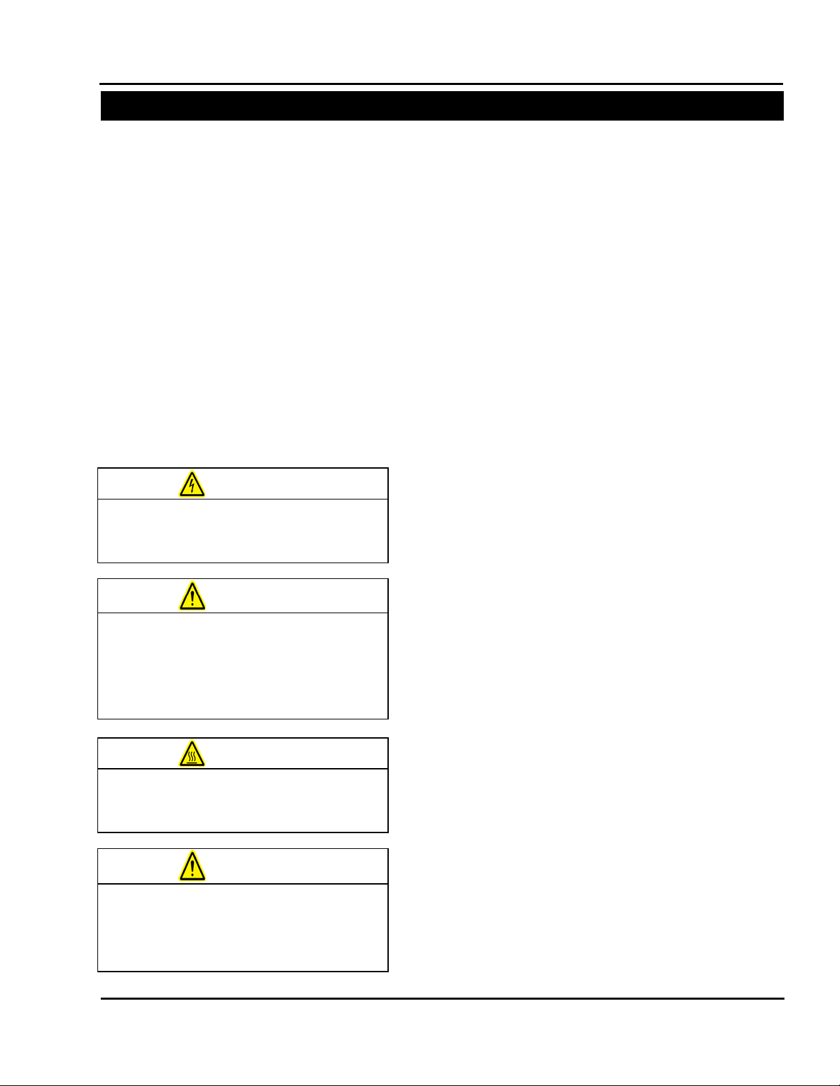
DEFINITION OF TERMS
Throughout this manual, you will find the
following safety notices with this accompanying
symbol. This symbol signifies important safety
issues regarding the oper ation and maintenanc e of
the Sharp SX™.
equipment. Failure to observe may result in
damage to the equipment and severe bodily
injury or death.
GENERAL CAUTION. Indicates information
equipment. Failure to observe may result in
damage to the equipment.
EQUIPMENT SAFETY FEATURES
The Sharp SX™ is equipped with a polycarbona t e
shield covering the pressure and heated seal bars.
DO NOT operate the unit with the shield removed.
Operating the unit without the safety guards in
place may result in serious bodily injury or
death.
Service and Maintenance Manual 960714-02B © 2007 I2407
SAFETY RULES AND PROCEDURES
The machine requires regular, periodic
maintenance to ensure reliable service. No
maintenance should be performed unless the
safety precautions for maintenance are thoroug hly
understood.
• Follow all instructions in this manual for safe
operation.
• Follow all company and industry standard
safety policies regarding this kind of
machinery that ma y exceed thos e liste d in th is
manual.
• Keep all safety features, guards, interlocks
and sensors in good working order.
• ALWAYS turn off machine power, ensure that
all mechanical motion has stopped and allow
any heated components to cool down before
removing any machine parts.
place may result in serious bodily injury or
Always remove electrical power from the SX
Prior to operating or servicing the SX, remove
any loose jewelry, make certain clothing and
hair are not loose to interfere with or become
could result in severe bodily injury or death.
Page 3
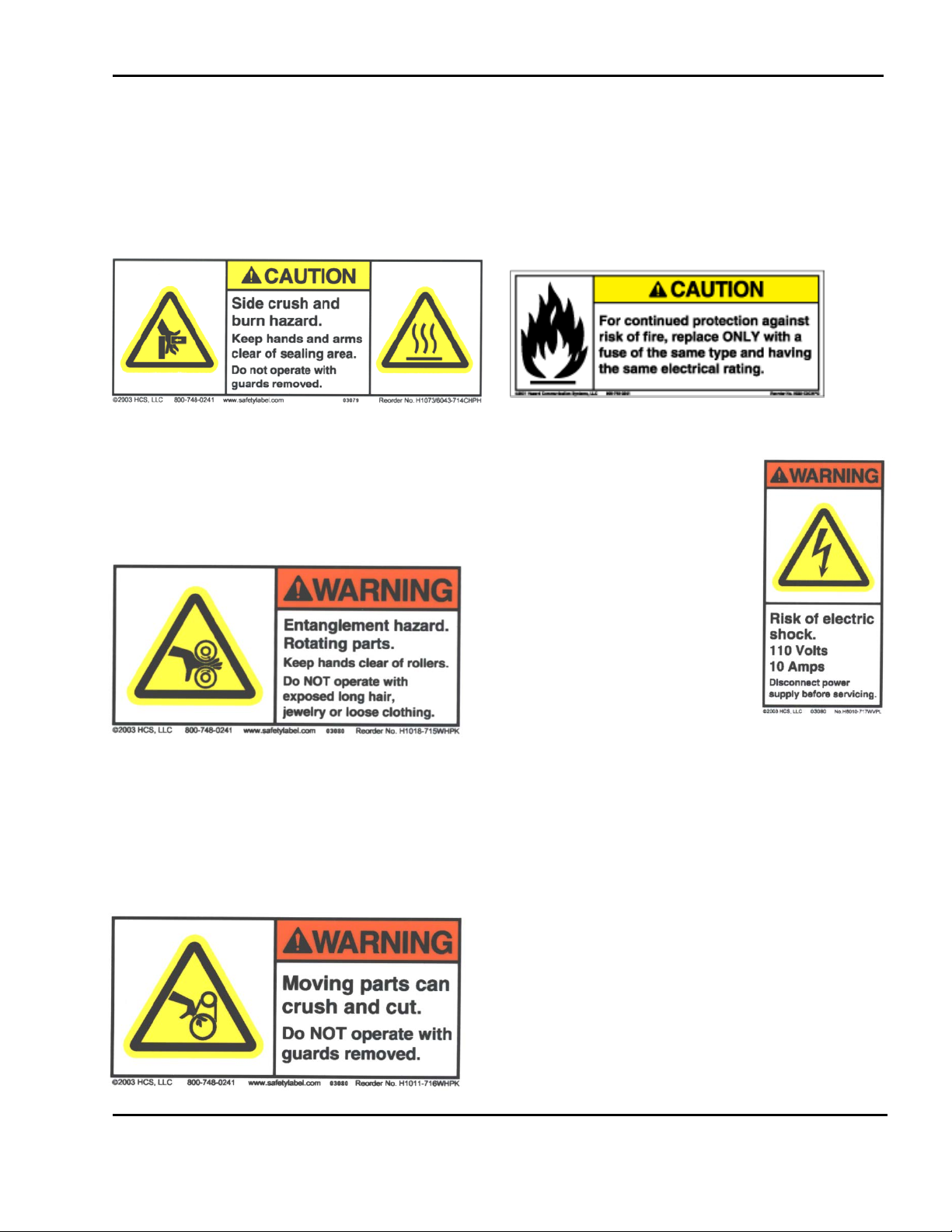
SAF ETY LABELS
The label shown on th e right
or panel guards electrical
to removing any guards
IMPORTANT SAFETY INFORMATION
SX™
The following label is placed on the Sharp SX™
wherever a removable shield or panel guards the
heated sealing area. Always disconnect electrical
power from the machine prior to removing any
guards and/or panels.
The following label is used where there is the
potential of your hands, long hair, jewelry, etc.
becoming entangled between two rotating parts.
Be sure to secure loose item s before approaching
and operating the machine.
The following label on the Sharp SX™ is located
where there is the potential of injury due to pinch
points or moving parts. Make certain electrical
power is disconnec ted befo re rem oving an y guards
and/or panels or servicing the machine.
The following label is locat ed in the proximity of a
fused circuit. Be certain to replace blown fuses
ONLY with fuses with the same electrical rating.
Always disconnect electrical power before
removing an y guards and/o r panels or s ervic ing the
Sharp SX™.
is placed on the Sharp SX™
wherever a removable s hield
components.
Always disconnect electrical
power from the mac hine pri or
and/or panels.
Service and Maintenance Manual 960714-02B © 2007 I2407
Page 4

Section 1- Introduction
TABLE OF CONTENTS
SX™
General Information ................................................ 1-1
About This Manual .............................................. 1-1
Model Variations ................................................. 1-2
Technical Assistance ......................................... 1-2
Theory of Operation ................................................. 1-3
General ............................................................... 1-3
Faults .................................................................. 1-4
EZ-Bags® and Film Materials ............................. 1-5
Thermal Transfer Ribbon .................................... 1-5
Specifications ........................................................... 1-6
Machine Specifications ....................................... 1-6
Packaging Specifications .................................... 1-6
Machine Dimensions ........................................... 1-6
Section 2 – Maintenance & Adjustments
Maintenance Schedule ............................................ 2-1
Daily Maintenance .......................................... 2-1
Annual Maintenance ........................................... 2-1
Cleaning .................................................................... 2-2
General ............................................................... 2-2
Cleaning the Printhead and Film Feed Rollers.... 2-3
Machine Adjustments .............................................. 2-5
Adjusting the Pinch Roller ................................... 2-5
Checking Belt Tension ........................................ 2-6
Checking Belt Tension ........................................ 2-7
Sharp SX™ with Printer ...................................... 2-8
Section 3 – Component Repair
Electrical Assembly ................................................ 3-1
Pressure Jaw and Film Feed Motor Controller s...3-1
Fuses .................................................................. 3-6
24VDC Power Supply ......................................... 3-8
Line Filter .......................................................... 3-16
Main Power Switch (RED)................................. 3-20
Transformers ..................................................... 3-22
Aromat PLC ...................................................... 3-27
Aromat PLC Battery .......................................... 3-28
Color Touch Screen .......................................... 3-30
Cooling Fan ....................................................... 3-33
Solid State Relay .............................................. 3-35
Grey Relay 24V ................................................ 3-39
Red Relay 24V .................................................. 3-41
Printer GPIO Board ........................................... 3-44
Printer Performance Logic Board ...................... 3-45
Printer Power Supply Board .............................. 3-46
24 VDC Fan Assembly...................................... 3-48
Laminated White Ribbon Cable ........................ 3-49
Datamax LCD Module....................................... 3-51
Printhead Stepper Drive .................................... 3-53
Film Feed Assembly .............................................. 3-56
Photoelectric Sensor ......................................... 3-56
Film Feed Motor Drive Belt ............................... 3-60
Film Feed Roller Drive Belt ............................... 3-61
Platen Roller Drive Belt ..................................... 3-63
Film Feed Roller ............................................... 3-67
Platen Roller ..................................................... 3-69
Film Feed Drive Motor ...................................... 3-72
Cradle Lock Cams ............................................ 3-74
Printhead Cradle Assembly .................................. 3-76
Ribbon Rewind Assembly ................................. 3-76
Ribbon Rewind Motor ....................................... 3-76
Primary Ribbon Drive Belt ................................. 3-79
DC Roller Clutch ............................................... 3-81
Secondary Ribbon Drive Belt ............................ 3-83
Adjustable Slip Clutch ....................................... 3-87
Printhead Position Assembly
Printhead Position Motor ................................... 3-89
Printhead Position Drive Belt ............................ 3-92
Printhead Pressure Cams ................................. 3-94
Printhead Position Sensor ............................... 3-100
Thermal Printhead ........................................... 3-102
Ribbon Supply Assembly
Slip Clutch Spring ............................................ 3-103
Ribbon Motion Sensor ..................................... 3-104
Ribbon Clips .................................................... 3-106
Gas Springs ..................................................... 3-107
Cross Flow Fan ................................................ 3-108
................................... 3-89
........................................ 3-103
Service and Maintenance Manual 960714-02B © 2007 I2407
Page 5

Cradle Latch Lever .......................................... 3-110
TABLE OF CONTENTS
SX™
Cradle Latch .................................................... 3-111
Sealer Assembly .................................................. 3-113
Pressure Bar Drive Motor................................ 3-113
Pressure Bar Gearbox .................................... 3-116
Pressure Bar Belt ............................................ 3-118
Linear Bearings ............................................... 3-120
Stripper Plate Assembly .................................. 3-122
Sealpoint Components .................................... 3-129
Seal Wire Tension Springs.............................. 3-132
Stripper Plate Sensors .................................... 3-135
Jaw Position Sensors ...................................... 3-140
Unwind Assembly ................................................ 3-145
Appendix
Replacement Parts Order Form .......................... A-1
Warranty ............................................................. A-2
Protecting Your Printhead ................................... A-3
Printer Menu Structure ........................................ A-6
Wiring Diagram – Located in the back of this
binder or Click Here
Unwind Spring ................................................. 3-145
Section 4 – Troubleshooting
Troubleshooting Chart ........................................ 4-1
Section 5 – Parts Lists
Electrical Assembly ............................................. 5-1
Film Feed Assembly ........................................... 5-3
Frame Assembly ................................................. 5-4
Printhead Cradle Assembly (Model 1108)........... 5-5
Cradle Assembly (Model 1097) ........................... 5-9
Sealer Assembly ............................................... 5-10
Unwind Assembly ............................................. 5-12
Section 6 – Assembly Drawings
Electrical Assembly ............................................. 6-1
Film Feed Assembly ........................................... 6-5
Frame Assembly ................................................. 6-6
Printhead Cradle Assembly (Model 1108)........... 6-9
Cradle Assembly (Model 1097) ......................... 6-14
Sealer Assembly ............................................... 6-17
Unwind Assembly ............................................. 6-20
Service and Maintenance Manual 960714-02B © 2007 I2407
Page 6

SX™
SECTION 1 – INTRODUCTION
GENERAL INFORMATION
This manual is designed to be used b y Authorized Service Pers onnel only. Sharp
Packaging Systems, Inc. assumes no responsibility for any repairs made on Sharp
Packaging units by anyone other than Authorized Service Technicians.
TESTING
ADJUSTMENT
REPLACEMENT
ABOUT THIS MANUAL
This manual has been prepared for your use in
servicing the Sharp SX™ Packaging Mac hine and
the Sharp SX™ Packaging Machine with Printer.
Included in the procedures are helpful facts on
service, troubleshooting, specifications and parts
information.
All procedures shoul d be performed by a qualified
service technician.
It is important that you f amiliarize yourself with the
product as much as possible before initiating any
maintenance, troubleshooting or repairs.
Make sure you read through the IMPORTANT
SAFETY INFORMATION and INTRODUCTION
sections of this manual before attempting any
service procedures.
As you disassemble your machine to service and replace parts, keep the following points in mind:
• Do not remove or loosen more parts than
needed. Use comm on sense to k eep your work
to a minimum.
• Mark any wires before disconnecting to make
reassembly easier.
• Use Loctite® Blue or eq uivale nt on al l threaded
fasteners without lock washers.
Within the Component Repair section of this
manual, each repair pr ocedure is broken do wn into
three main categories for each component . These
categories are Testing, Adjustment, and
Replacement and are identified by the following
symbols:
Accompanying this manual, attached to the inside
front cover, is a Compact Disc containing an
electronic color vers ion of this m anual in Ac robat .pdf
format along with other useful digital content. For
more information vie w the README.TXT file located
on the CD.
Adobe Reader is required to view .pdf files and can
be downloaded free of charge from the following
website:
http://www.adobe.com/products/acrobat/alternate.html#50
The digital color version of the manual is also
interactive, allowing the user to simply click onto a
subject within the Table of C ontents to take them to
the specified page.
Service and Maintenance Manual 1-1 960714-02B © 2007 I2407
Page 7
SX™
SECTION 1 – INTRODUCTION
GENERAL INFORMATION
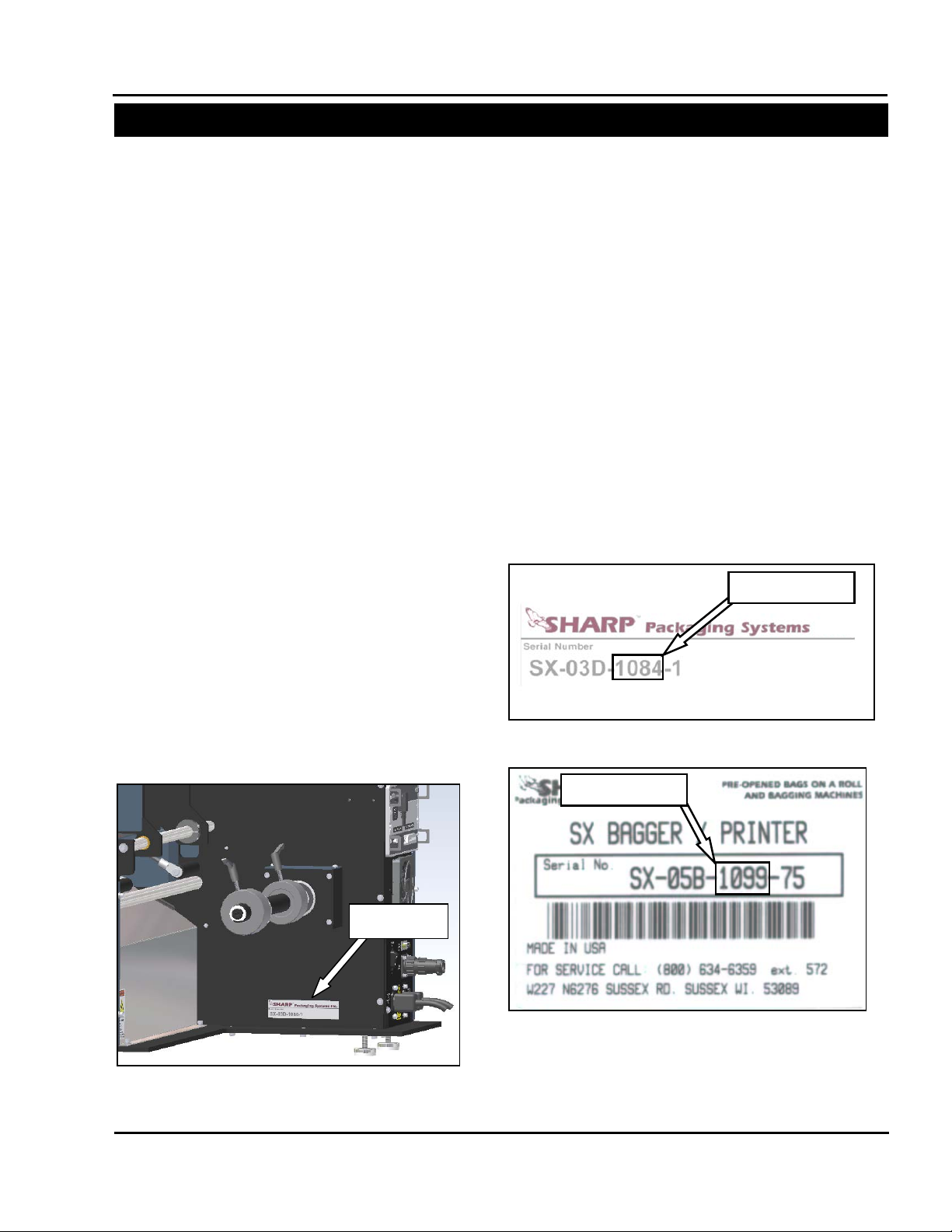
Figure 1-1. Serial Tag Location
Serial Tag
Figure 1-2. Model 1075 and 1084 Serial Tag
Model Number
Figure 1-3. Model 1097, 1099, 1108, and 1109
Model Number
MODEL VARIATION
This manual has been developed to assist in
servicing and maintaining the Sharp SX™ with
Printer model 1108 and the Sharp SX™ model
1109. Although th is manual has been written for
this specific model, the procedures and
techniques for replacing components and
troubleshooting can generally be applied to all
models of the SX™. Major differences in
machine maintenance or component repair will
be noted on a case by case basis. T he parts lists
and assembly drawings located in secti ons 5 and
6 of this manual are specifically for these two
models. If a replacement part is needed for an
older model of machine, please refer to the CD
located in the front of this manual. This CD
contains the parts lists and assembly drawings
for all previous m odels of the Sh ar p SX™ and the
Sharp SX™ with Printer.
The replacement parts lists located on the CD
have been separated by model number for ease
of identifying the parts that are needed. Sim ply
locate the section of the manual that coincides
with the SX™ model you have and proc eed from
there.
TECHINCAL ASSISTANCE
Assistance with the SX™ can be obtained by
notifying Sharp Packaging Systems at:
Sharp Packaging Systems
PO Box 124
Sussex, WI 53089, USA
Service: 800-634-6359 (ext. 572)
service@sharppackaging.com
Parts: 800-634-6359 (ext. 571)
parts@sharppackaging.com
Fax: 262-246-3387
To determine which m odel of t he Shar p SX™ you
have, refer to Figure 1-1. The serial number is
located on a placard or sticker directly below the
roll unwind shaft. The highlighted numbers in
Figures 1-2 and 1-3 coincide with the model of
the machine.
Serial Tag
Service and Maintenance Manual 1-2 960714-02B © 2007 I2407
Page 8
SX™
SECTION 1 – INTRODUCTION
THEORY OF OPERATION
is equipped with a jaw
not designed, nor intended, to be a safety
WARNING
GENERAL
The Sharp SX™ is controlled by a PLC
(Programmable Logic Controller). The PLC
receives input from the operator touchscreen to
control a stepper drive motor and an electric eye
sensor on the bag feeder output end.
The Sharp SX™ is equi pped with a sensor on the
pressure jaw which c a n d et ec t an obs truc ti on. If an
object triggers the sensor , the pressure jaw motor
will reverse, and place the bagger into a fault. A
message appears on the control panel displaying
the jaw fault, allo wing the operator to clear t he seal
area and restart the bagging cycle.
Note: the Sharp SX™ is n ot designed to interface
with automatic infeed units such as counters,
scales, or infeed conveyors.
The Sharp SXTM
obstruction detection sensor. This sensor is
sensor.
• The Sharp SX™ uses pre-opened Sharp EZ-
• A constant stream of air opens (inflates) the
• Product is loaded into the bag.
• Once the bag is loaded , t h e op erator cycles the
• The pressure jaw closes and grips the bag.
• An electric eye is used to sense the trailing
. The bags are dispensed through the
Bags
powered drive rollers.
bag, preparing the bag to be loaded.
machine (either by foot control, optional dual
optical palm buttons, f rom the Touchscreen or
the machine can be set on autom atic cycle) to
seal the bag.
The impulse sealer heats up and seals the bag
while the power drive rollers reverse to
separate the bag at the perforation.
edge of the bag. Hang holes , vent holes, etc.
must be prevented from passing over the
electric eye as this will send a false signal to
Service and Maintenance Manual 1-3 960714-02B © 2007 I2407
the PLC. To prevent this, the e lectric eye has
been designed to be off center of the bag,
however, in som e cases the bags m ay have to
be repositioned when larger hang holes, vent
holes, etc. are present (see Loading Bag Film).
• When the bag is sealed and seal dwell is
complete, the pressure jaw opens.
• The Printhead is lowered and the bag is
indexed forward at prin tin g s peed unt il th e l abe l
is completed. The Printhead is raised and the
balance of the bag length is index ed forward at
full index speed (bagger speed). (Note: This
step occurs only if model is equipped with an
imprinter)
• As the bags are indexed, the Mat erial Unwind
Shaft will spin allowing the bags to be pulled
from the roll. The Material Unwind Shaft is
comprised of a Roll Tensioner with
compression spring, Cor e Chuc k, and a t orsion
spring. When the roll of bags is loaded onto
the machine, pressure is applied to the Roll
Tensioner which in turn applies press ure to the
roll side plate c reat ing a kind of slip clutch. The
pressure that is ap plied t o t he Rol l Tens ioner is
directly proportional to the type and thickness
of the material being used. As this pressure
increases the amount of tension on the web
also increases. The appropriate amount of
pressure that should be applied to the Roll
Tensioner can be found using trial and error.
• The constant stream of air inflates the bag,
preparing the bag to be loaded.
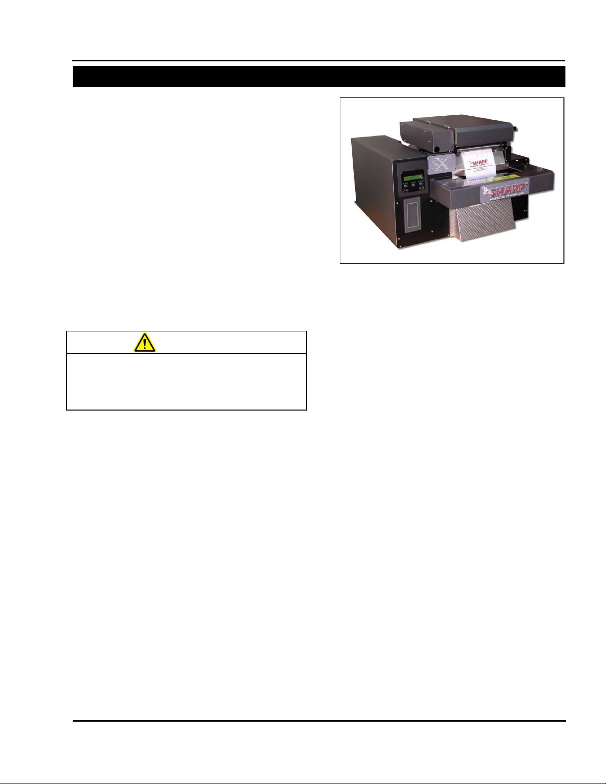
Figure 1-4. Sharp SX™
Page 9

SX™
SECTION 1 – INTRODUCTION
THEORY OF OPERATION
FAULTS
The Sharp SX™ has been designed to alert the
operator, via the Touc hscreen, to a situat ion (fault)
that requires immediate attention. These faults
may indicate a serious condition where, if not
corrected, damage to the unit may occur or the
fault may simply alert the o perator that th e unit has
run out of film. The following is a list of possible
faults that may occur duri ng operation. A detailed
list of faults, causes an d solutions can be found in
the Troubleshooting section of this manual.
• WEB DID NOT BACK UP
The machine reverses the drive rollers to separate
the web of bags at the per f or ation. T he b ag ger has
a photo eye that it uses to detect the trai ling edge
of the bag. When the photo eye does not detect
this trailing edge w ithin the allowed time, this fault
is triggered.
• JAW FAULT
The Obstruction Sensing Jaw has detected an
object in the sealing area during the sealing
operation.
• OBSTRUCTION SENSING JAW TIMER
FAULT
The Obstruction Sensing Jaw did not close within
the preset time, but there was no obstruction
sensed.
• THERE ARE NO BAGS COVERING THE EYE
This fault is triggered when the machine cycle is
initiated and the photo eye is not activated.
• BATCH IS COMPLETE
This message is activated when the bagger has
cycled the specified number of times set by the
operator under Batch Target.
Batch Target – A predetermined num ber of cycles
that will be completed before the machine will
automatically stop.
• WAITING FOR PRINTER SIGNAL*
The bagger has sent a print signal to the printer
and is waiting for a return signal.
*Note: This f ault w il l on ly oc cur if the Shar p SX™ is
equipped with an imprinter.
Service and Maintenance Manual 1-4 960714-02B © 2007 I2407
Page 10

SX™
SECTION 1 – INTRODUCTION
THEORY OF OPERATION
SHARP EZ-BAGS
AND FILM MATERIALS
The Sharp SX™ is design ed to use a wide variety
of bag sizes and materials. Sharp EZ-Bags
recommended for opt imum operating performance,
efficiency and safety. System performance
specifications are based on utilizing consistent,
high quality, pre-ope ned bags . Any bag used mus t
meet Sharp Packaging Systems’ manufacturing
tolerances. The following list shows some of the
Sharp EZ-Bags
films available through Sharp
Packaging Systems, Inc.
• Low Density Polyethylene (LDPE)
• Linear Low Density Polyethylene (LLDPE)
• High Molecular Weight, High Density
Polyethylene (HMWHDPE)
• Laminated Oriented Polypropylene
(Laminate/OPP)
• Polypropylene
• Metallic Films (including conductive films)
• Co-Extruded Films (combination films)
• Other Laminates (any other laminates
laminated with polyethylene)
• Anti-static and Triboelectric films
• VCI corrosion inhibiting films
• Opaque films
Contact Sharp Customer Service (800-634-6359) or
www.customerserviceteam@sharppackaging.com
to order Sharp EZ-Bags
regarding film and bag specifications.
and for information
are
THERMAL TRANSFER RIBBON*
The Sharp SX™ uses thermal transfer ribbon to
print variable information onto the bags as they
pass through the mac hine. The follo wing is a list of
ribbon that is available through Sharp Packaging
Systems, Inc. For ordering inf ormation refer to the
Replacement Parts Order F orm i n the Append ix on
page A-1.
• Standard Direct Wax Ribbon
• Premium Wax Resin Ribbon
*Note: Used only if the Sharp SX™ is equipped
with an imprinter.
SUPPLIES
Thermal Transfer Ribbons
Sharp thermal transfer ribbons are selected
specifically for use with our printer. Use of ribbons
other than those suppli ed by Sharp, m ay result in a
poor quality printing , especiall y bar-codes and th eir
ability to be succes sfully scanned. This may also
void the print head warranty.
Recommended Sharp ribbons are:
• Black ink, scratch and smudge resistant
• 2000’ (609 meters), 3.5 to 4.5 microns thick
• 1” core, no notch required
• Ink side in
• Back coated ribbons only
Special purpose thermal transfer ribbons, sizes
other than those listed above, such as colored
ribbons, or low temperature release ribbons are
available.
Service and Maintenance Manual 1-5 960714-02B © 2007 I2407
Page 11

SX™
SECTION 1 – INTRODUCTION
SPECIFICATIONS
Minimum
Maximum
Bag Width
Bag Length
Film Gauge
2” (5.08 cm)
4” (10.16 cm)
9” (22.86 cm)
32” (81 cm)
.004” (4 mil) 100 microns
.001” (1 mil) 25 microns
Width
Height
Depth
Weight
Power
Rate
Operating
Humidity
** Size of package along with weight and size of product will cause rate to vary.
35.25" [89.54 cm]
26.75" [67.94 cm]
26.00" [66.04 cm]
PACKAGING SPECIFICATIONS
MACHINE SPECIFICATIONS
26.75”
(67.9 cm)
19”
(48.3 cm)
35.25”
(89.5 cm)
DIMENSIONS
200 lbs.
(91 kg)
Req.
115 VAC
50/60 Hz
15 Amps
35**
bags per
minute
Temp
0°-40°C
32°-140°F
Range
10%-90%RH
Non-
Condensing
Service and Maintenance Manual 1-6 960714-02B © 2007 I2407
Page 12

SX™
SECTION 2 – MAINTENANCE AND ADJUSTMENTS
MAINTENANCE SCHEDULE
on the machine.
WARNING
Always remove electrical power from the
prior to performing any maintenance
SX
DAILY MAINTENANCE
• Inspect the electric eye. Clean with a c otton
swab if dirty. Do not use any solvents or
cleaning solutions on the s ensing portions of
the electric eye.
• Clean any excess material from the drive
roller and platen roller on the film feed
assembly. Plastic com pounds tend to buildup on the rollers. Clean regular ly with a soft,
lint-free cloth using a rubber platen roller
conditioner/cleaner or isopropyl alcohol.
• Inspect Teflon tape on the seal wire and
replace if damaged or worn.
• Inspect the anvil rubber on the pressure bar
assembly and replace if damaged or worn.
• Inspect all electrical li nes for any sign of wear
or damage. Replace any lines that appear
worn or unsafe.
• If the Sharp SX is equipped with a printer,
the printhead needs to be cleaned with a
soft, lint-fr ee cloth a nd is oprop yl alcoho l. T his
will be explained further on page 2-3 in the
section entitled “Cleaning the Printhead and
Film Feed Rollers.”
ANNUAL MAINTENANCE
• Check all electrical connections.
• Check entire machine for loose bolts or nuts.
• Inspect all drive belts for excessive wear and
slack.
• Grease the four pressure bar linear guide
bearings using lithium grease (JIS Type 2).*
• Apply a light film of grease to the pressure
bar rack and pinion gearing using lithium
grease (JIS Type 2).*
* Note: The recommended lubrication interval for
the linear guide bearings based on total travel is
approximately 500,000 cycles. Sharp Packaging
Systems suggests greasing the bearings at this
frequency or once a year, whichever comes first.
Both the linear guide be arin gs and th e pr ess ur e bar
gear rack and pinion gear can be lubricated with
the same frequency.
MONTHLY MAINTENANCE
• Clean the foam element located on the
cooling fan on the rear of the machine with
water, wring out, and reinstall.
Service and Maintenance Manual 2-1 960714-02B © 2007 I2407
Page 13
of the machine with any liquid while
components can cause shorts,
WARNING
WARNING
the machine prior to performing any
WARNING
Do not attempt to clean the machine
injury or death.
WARNING
SX™
SECTION 2 – MAINTENANCE AND ADJUSTMENTS
CLEANING
GENERAL
This machine requires regular, periodic
cleaning to ensure reliable service. Shift and
daily cleaning can be performed by the
operator with a minimum of training.
Regular cleaning is important for the proper
operation and performance of the machine.
During operation there wil l be a normal buildup
of dirt, dust, and lubricants on various parts of
the machine. If using the Sharp SX™ with
Printer, ink rubbed off of printed film can also
build up.
The machine and areas directly adjacent to it
should be kept clean of debris as these can
create safety hazar ds for the operator and the
machine.
Disconnect electrical power cords from
maintenance on machine.
Do not spray the electrical components
power is applied. Liquids on electrical
damaging the components and causing
personal injury or death.
Avoid hot surfaces. Do not service the
machine until the heated surfaces have
cooled after disconnecting power.
while it is running. Cleaning the
machine while it is running can damage
the machine and cause severe personal
No cleaning should be performed unless these
safety precautions are thoroughly understood and
are adhered to without exception.
Clean machine surfaces during each pause in
production – NEVER while the machine is running.
Remove contaminants a nd debr is, and use a c lean,
soft lint-free cloth to wipe down the machine.
• Inspect the machine to determine if there has
been an accumulation of dust or other
contamination. Clean if necessary.
• ALWAYS SHUT OFF AND UNPLUG machine
power cord before cleaning or removing any
guards.
• NEVER defeat an y saf et y d evic e or i nterlock on
the machine.
• DO NOT use steel wool on machine surfaces.
Particles of steel wool m ay break off and cause
rusting or contaminate lubricated surfaces.
• DO NOT allow wrenches, fittings or other
metallic objects to lie on machine surfaces
during production.
• DO NOT use chlorine, am monia, alkalis, acids,
or cleaning solutions that will damage m etallic
machine surfaces, cause corrosion or
contaminate containers.
Service and Maintenance Manual 2-2 960714-02B © 2007 I2407
Page 14

on the machine.
WARNING
Do not pour isopropyl alcohol or any
cleaning solution directly onto the
the machine.
CAUTION
Cradle
Cradle Latch
Figure 2-1. Opening the Printhead Cradle
Figure 2-2. Cleaning the Printhead
Thermal
SX™
SECTION 2 – MAINTENANCE AND ADJUSTMENTS
CLEANING
CLEANING THE PRINTHEAD & FILM
FEED ROLLERS
*Note: This section is specifically for t he Model
with Printer . If your model does not have
SX
a printer, only follow st eps 5 and 6 for clean ing
the film feed drive roller.
Always remove electrical power from the
1. With power removed from the machine,
2. Gently slide the ribbon to the side to
3. Moiste n a soft, lint-free cloth with is opropyl
4. Slide the ribbon into its original position.
prior to performing any maintenance
SX
release the cradle latch to grant access to
the printhead and the rubber rollers on the
film feed assembly. Also, open the
printhead cradle cover (Figure 2-1).
expose the printhead.
alcohol and gentl y wipe the surf ace of the
printhead to clean dust and residue from
the surface, as shown in Figure 2-2.
printhead or rollers. Liquids may short
electrical components, causing damage to
Make approximately ten tur ns on t he ribbo n
rewind hub to take up slack and wrinkles,
ensuring it is completel y flat over the rib bon
rollers and printhead.
Service and Maintenance Manual 2-3 960714-02B © 2007 I2407
Cover
Printhead
Page 15

SX™
SECTION 2 – MAINTENANCE AND ADJUSTMENTS
CLEANING
Figure 2-3. Cleaning the Film Feed Drive Roller
Film Feed
Platen
Roller
CLEANING THE PRINTHEAD & FILM
FEED ROLLERS (cont.)
5. Rem oisten the lint-free cloth with isopropyl
alcohol and rub back and forth along film
feed drive roller as shown in Figure 2-3.
Clean roller until residue is removed. Be
careful not to damage rubber coating on
roller, as this will affect machine
performance.
6. Manually rotate film feed drive roller, and
repeat procedure in step 5. Continue
wiping and rotating until the entire surface
of the drive roller is clean.
7. Repe at steps 5 and 6 on the platen roller,
again being careful to not damage the
rubber surface.
Drive Roller
8. When both rollers are clean, thread bag
film through the machine, and close the
printhead cradle cover. Turn the cradle
latch to the locked position.
Service and Maintenance Manual 2-4 960714-02B © 2007 I2407
Page 16
SX™
SECTION 2 – MAINTENANCE AND ADJUSTMENTS
MACHINE ADJUSTMENTS
SX™
SECTION 2 – MAINTENANCE AND ADJUSTMENTS
MACHINE ADJUSTMENTS
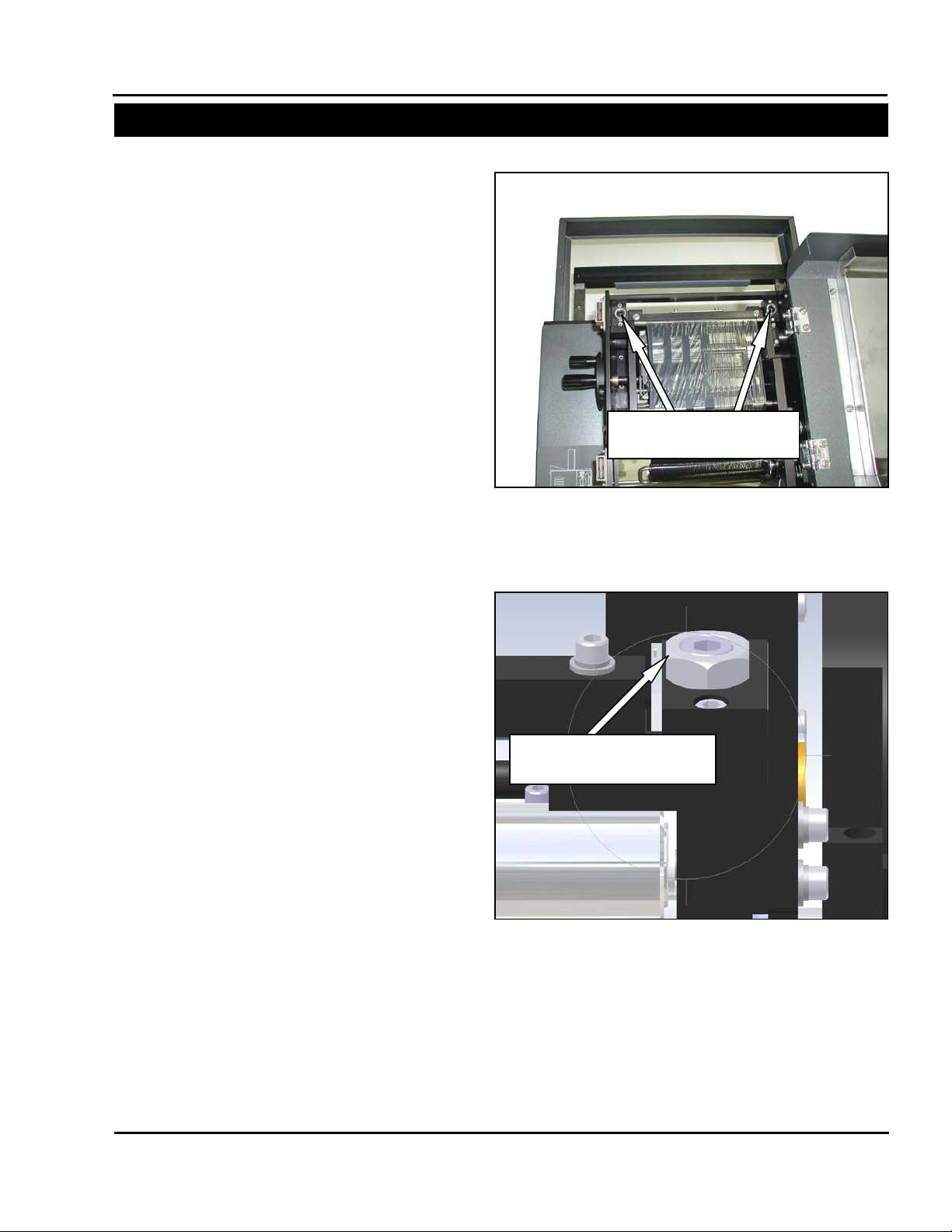
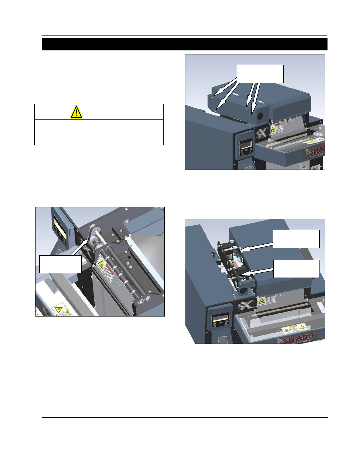
Figure 2-4. Pinch Roller Adjustment Screws
Pinch Roller
Adjustment Set Screws
Figure 2-5. Jam Nut and Set Screw
Set Screw and Jam Nut
Flush for Initial Adjustment
ADJUSTING THE PINCH ROLLER
The pinch roller adjustment is used to control
excess “traveling” of the film to either side of the
pinch roller. This traveling is due to uneven
pressure distributed by the pinch roller onto the
drive roller. This pressure is created by slidespring mechanisms on each end of the pinch ro ller.
Under normal usage, the pinch roller should not
come out of adjustment. Before changing the
factory settings on the pinch roller, be sure to check
the unwind for proper web tension and alignment.
If changing the roll setting does not prevent
traveling, follow these steps to adjust the pinch
roller tension.
1. O pen the printhead cradle cover to expose the
printhead components and pinch roller.
2. Confirm the preset adjustment of the pinch
roller. The top of the set s crew should be flush
with the top of the hex jam nut. If either side is
not flush, turn the j am nut counter-clockwise to
unlock the set scr ew. Adjust the set screw to
the proper height, an d retighten the jam nut to
lock into place. Clos e cradle cover, and cycle
machine to check for traveling issues.
3. If the pinch roller adjustment springs are set
correctly and the film still travels, release the
jam nut and turn the set screw opposite the
side the media is pulling towards down in 1/4
turn increments. Loc k the jam nut, and check
for traveling. Continue this process until the
bag film feeds out ev enly and does n ot walk to
either side.
Service and Maintenance Manual 2-5 960714-02B © 2007 I2407
Service and Maintenance Manual 2-5 960714-02B © 2007 I2407
Page 17
SX™
SECTION 2 – MAINTENANCE AND ADJUSTMENTS
MACHINE ADJUSTMENTS
on the machine.
WARNING
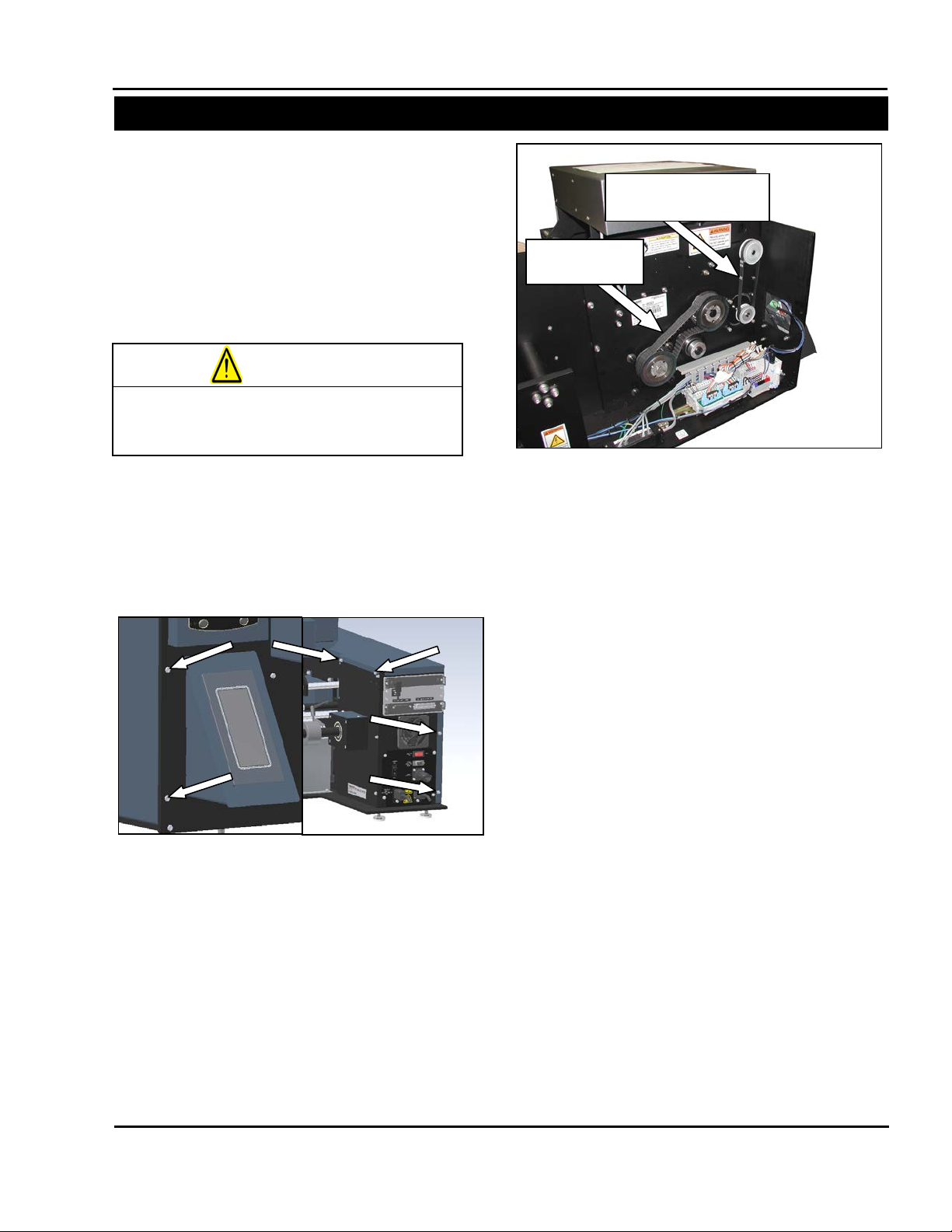
Figure 2-7. Pressure Bar and Film Feed Belts
Pressure Jaw
Drive Belt
Film Feed Motor
Drive Belt
Figure 2-6. Frame Cover Screws
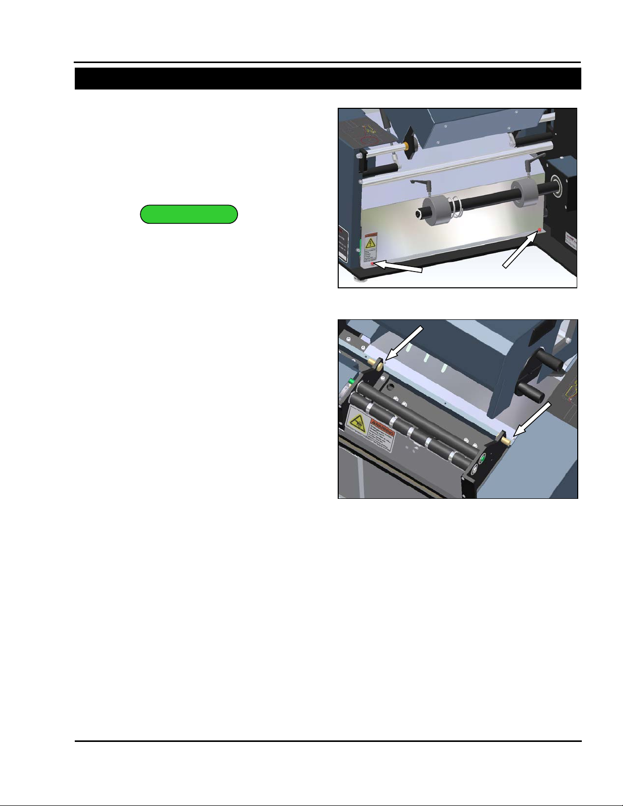
CHECKING BELT TENSION
Sharp SX
The Sharp SX has three belts, one whic h drives
the pressure jaw and two that drive the film feed
drive roller. To ensure proper operation of the
machine, these belts ne ed t o be c hecked for proper
tension to avoid slip.
Always remove electrical power from the
1. With machine power disconnected, remove
2. Locate the pressure jaw drive belt (Figure 2-
prior to performing any maintenance
SX
the left side frame guard. Remove the two
screws on the rear face plate, the t wo screws
on the front face plate, and the two s crews on
the middle unwind plate (Figure 2-6).
7). Depress the center of the belt to
determine if the tension is appropriate. The
belt should deflect approximately 1/8” when
depressed with one finger at the center of the
longest belt span.*
3. If the belt deflects more than 1/8 loosen the
four motor mounting screws and apply
downward pressure to the pressure bar drive
motor. When m otor is in desired position for
proper belt tension, tighten four screws and
verify the belt deflects the recommended
amount. Repeat until belt is correctly
tensioned.
4. Locate the film feed motor drive belt (Figur e 2-
7). Repeat the process in step two to check
for correct tension. This belt should deflect
approximately 3/32” at proper tension. If too
tight or too loose, repea t step thr ee o n the f ilm
feed drive motor.
*Note: Belt tension shou ld be just e nough to ensure
a positive interference between belt and sprocket
teeth without allowing th em to jum p. If too t ight , t he
load may cause undue stress on the shafts and
shorten belt life. If too loose, the belt will not
engage the sprocket pr operly and the drive w ill slip
under normal loads. For a mor e de tai led method of
determining proper belt tension, contact Sharp
Packaging Systems customer service or consult
the belt manufacturer.
Service and Maintenance Manual 2-6 960714-02B © 2007 I2407
Page 18
SX™
SECTION 2 – MAINTENANCE AND ADJUSTMENTS
MACHINE ADJUSTMENTS
Film Feed Roller
Drive Belt
Figure 2-8 Pulley Guard Screws
Note: Cradle Removed for Clarity
Sharp SX (con’t)
5. Rele ase the cradle latch and open the c radle.
Remove the pulley cover to expose the drive
roller belt.
6. Chec k the film feed drive roller belt for tension
(Figure 2-9). This belt should deflect
approximately 1/16” using one finger to push
on the center of the belt span. If adjustment is
needed, loosen the idler screw and slide to
increase tension. Retighten screw and check
tension.
7. Reinstall frame guard and pulley guard that
were removed earlier. Clos e cradle and lock
into position.
Service and Maintenance Manual 2-7 960714-02B © 2007 I2407
Page 19
SX™
SECTION 2 – MAINTENANCE AND ADJUSTMENTS
MACHINE ADJUSTMENTS
on the machine.
WARNING
Figure 2-12. Ribbon Rewind Motor Belt and
Ribbon Rewind
Motor Belt
Printhead Lift
Drive Belt
Figure 2-10 Platen Roller Drive Belt
Note: Cradle Removed for Clarity
Platen Roller
Drive Belt
Outside Cradle
Screws
Figure 2-11. Removing the Outside Cr ad le Cov er
Sharp SX with Printer
The Sharp SX with Printer utilizes seven drive
belts during operation: one to drive the pressure
jaw, two to drive film feed roller s, one for the plat en
roller, one for the printhead lift cams, and two to
drive the printer ribbon rewind hub.
Always remove electrical power from the
prior to performing any maintenance
SX
1. Foll ow steps 1 through 6 o n pages 2-6 and 2-7
to check for proper tensio n of the pressure bar
drive belt and the two film feed drive belts.
2. Check the platen roller drive belt for tension
(Figure 2-10). This belt should deflect
approximately 1/16” using one finger to push
on the center of the belt span.
3. If belt tension is incorrect, loosen the idler
screw and slide idler t o add or rem ove tension.
Tighten screw and check belt. Repeat as
necessary.
4. Repl ac e t he pu lley guard by reinstall ing th e t wo
mounting screws.
5. Rem ove the four screws that hold the outside
cradle cover (Figure 2-11). Slide the cover off
to expose the ribbon r ewind hub drive and the
printhead lift drive.
6. Chec k the tension on the ribbon rewind motor
drive belt (Figure 2-12) using the same
procedure for the film feed drive belt. This belt
should deflect about 1/16”.
Printhead Lift Drive Belt
7. If belt does not have proper tension, loosen
four motor mounting screws and apply
pressure to motor towards the rear of the
machine. Retighten motor screws and check
for tension. Repeat as necessary.
Service and Maintenance Manual 2-8 960714-02B © 2007 I2407
Page 20
SX™
SECTION 3 – COMPONENT REPAIR
MACHINE ADJUSTMENTS
Ribbon Rewind
Slip Clutch Belt
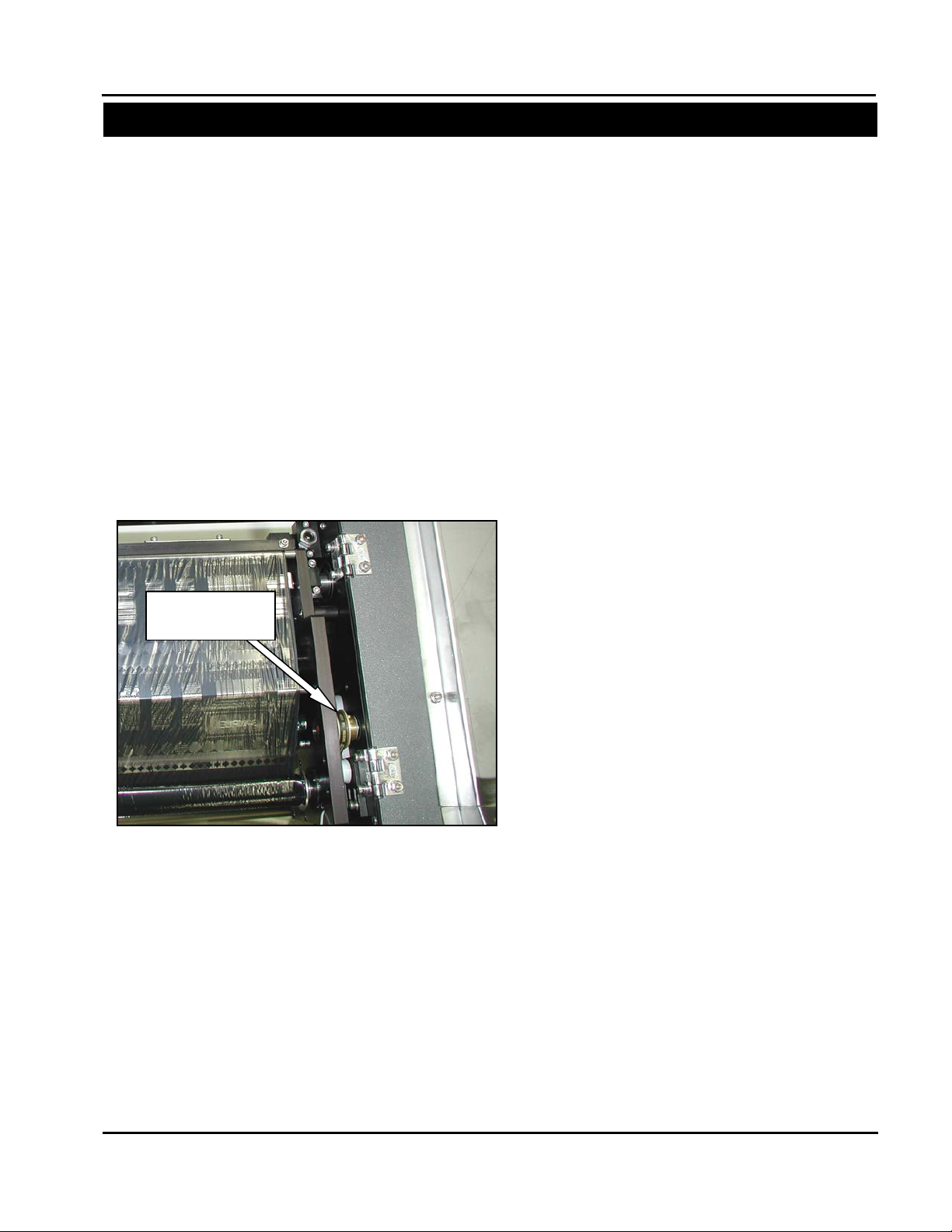
Figure 2-13. Ribbon Rewind Slip Clutch Belt
Sharp SX with Printer (con’t)
8. Check the tension on the printhead lift drive
belt (Figure 2-12). This belt should deflect
1/16”. If incorrect, fol low method in step seven
to achieve proper tension.
9. Repl ace outsid e cradle c over, and reinstal l four
screws removed in step 5.
10. Close the printhead cradle and turn the latch
counter-clockwise to lock into position.
11. Open the top cradle cover by lifting on the
recessed plastic handle.
12. Locate the slip clutch belt between the left
printhead plate and the outer plate on the
hinged side of the cradle (Figure 2-13). At
proper tension, this belt should deflect about
1/16”.
13. To add or remove tension to this belt, loosen
the two screws on the idler plate and slide it
forward or backward to ad d or remove tension.
Tighten the screws, and rec heck belt. Repeat
as necessary.
14. Once all belt tensio ns have been check ed and
properly set, replace the side frame guard.
Service and Maintenance Manual 2-9 960714-02B © 2007 I2407
Page 21
SX™
SECTION 3 – COMPONENT REPAIR
ELECTRICAL COMPONENTS
TESTING
Figure 3-3. Fuse Probe Locations
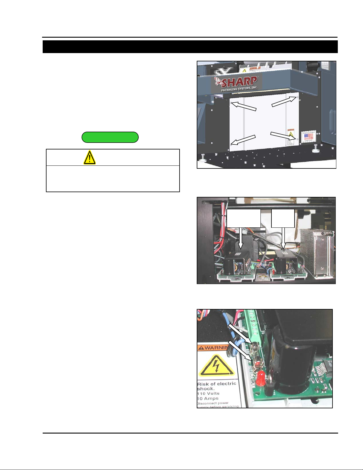
Figure 3-1. Load Plate Screws
Figure 3-2. TM4500 Drive locations
Pressure
Jaw
Film
Feed
on the machine.
WARNING
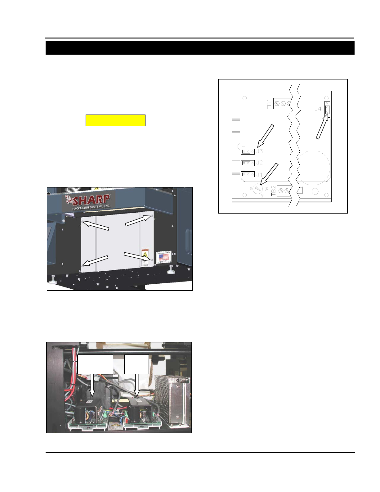
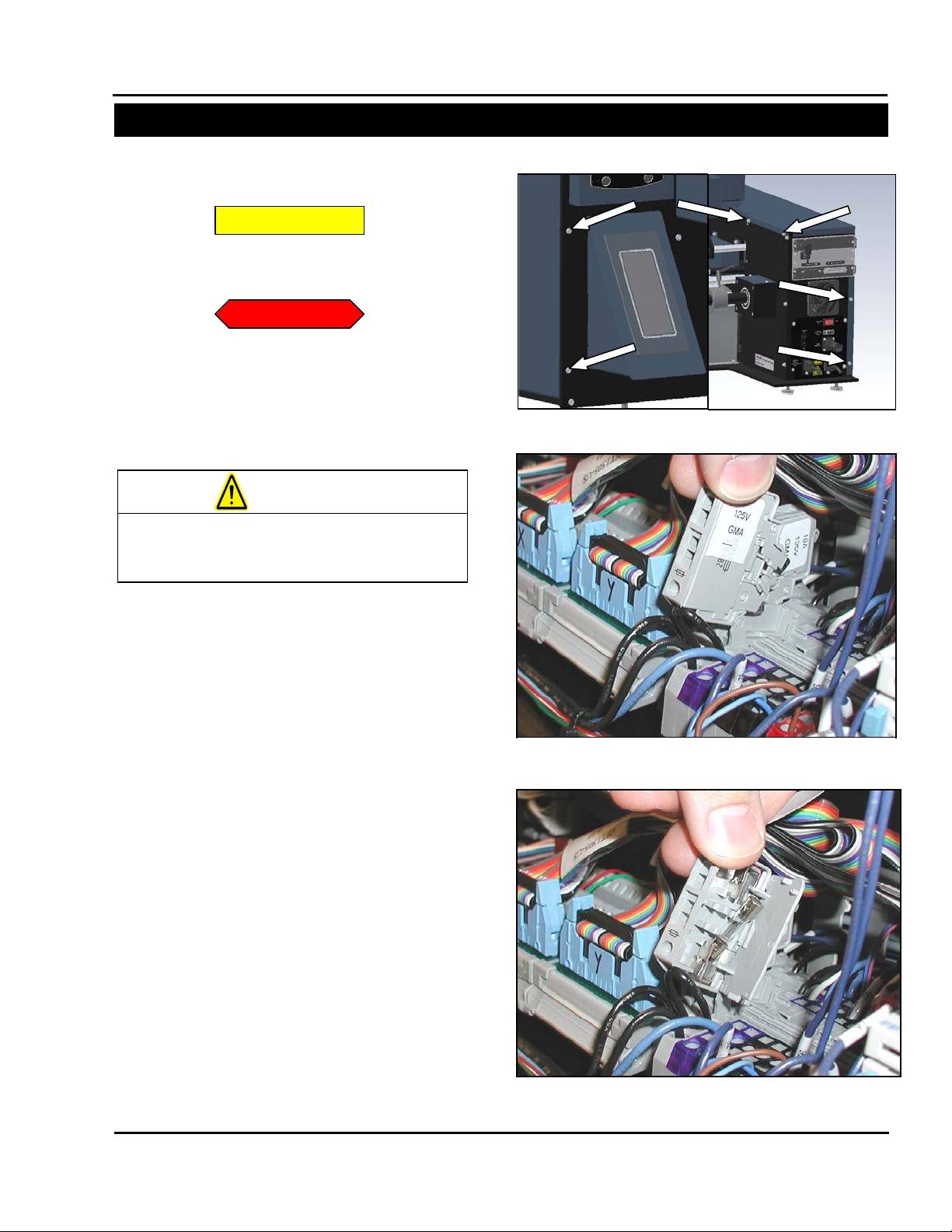
PRESSURE JAW AND FILM FEED MOTOR CONTROLLERS
The Sharp SX
technology to precisely control the movement of
various mechanical systems. This section will
describe how to service the two TM4500 stepper
drive units. These units control the Pressure Jaw
and Film Feed motors.
Always remove electrical power from the
prior to performing any maintenance
SX
1. Remove the four screws holding the Load
Plate, set screws and Load Plate aside (Figure
3-1).
2. Locate the two identical stepper drives inside
the Sharp SX
drive is on the left and the Film F eed drive is on
the right (Figure 3-2).
3. Loc ate the fuse on th e defective u nit (Figure 3-
3).
4. Set your Digital Volt/Ohm Meter (DVOM) to test
for continuity.
5. With the red probe, make contact with the
metal on one side of the fuse and with the
black probe make c ontact with the ot her side of
the fuse (Figure 3-3).
6. If your DVOM indicates that there is no
continuity, replace the fuse.
Note: A blown fuse can be an indication of a
larger problem. If you continue to blow fuses,
test the stepper motors and power
connections.
TM
bagger uses stepper drive
TM
Bagger. The Pressure Jaw
Service and Maintenance Manual 3-1 960714-02B © 2007 I2407
Page 22
SX™
SECTION 3 – COMPONENT REPAIR
ELECTRICAL COMPONENTS
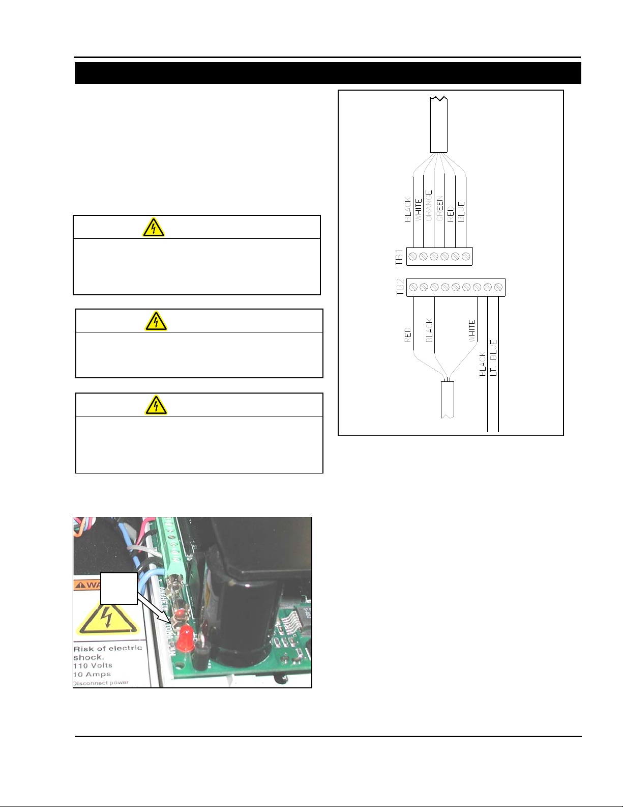
Figure 3-5. TM4500 Wiring Configuration
Figure 3-4. Status LED Location
Red
LED
MACHINE WHILE POWER IS APPLIED.
UNEXPECTED MACHINE STARTUP CAN
CAUSE SERIOUS INJURY.
WARNING
AND ARMS CLEAR OF MOVING PARTS.
WARNING
USE PROPER TROUBLESHOOTING
TECHNIQUES TO AVOID ELECTRICAL SHOCK.
WARNING
PRESSURE JAW AND FILM FEED
MOTOR CONTROLLERS (con’t)
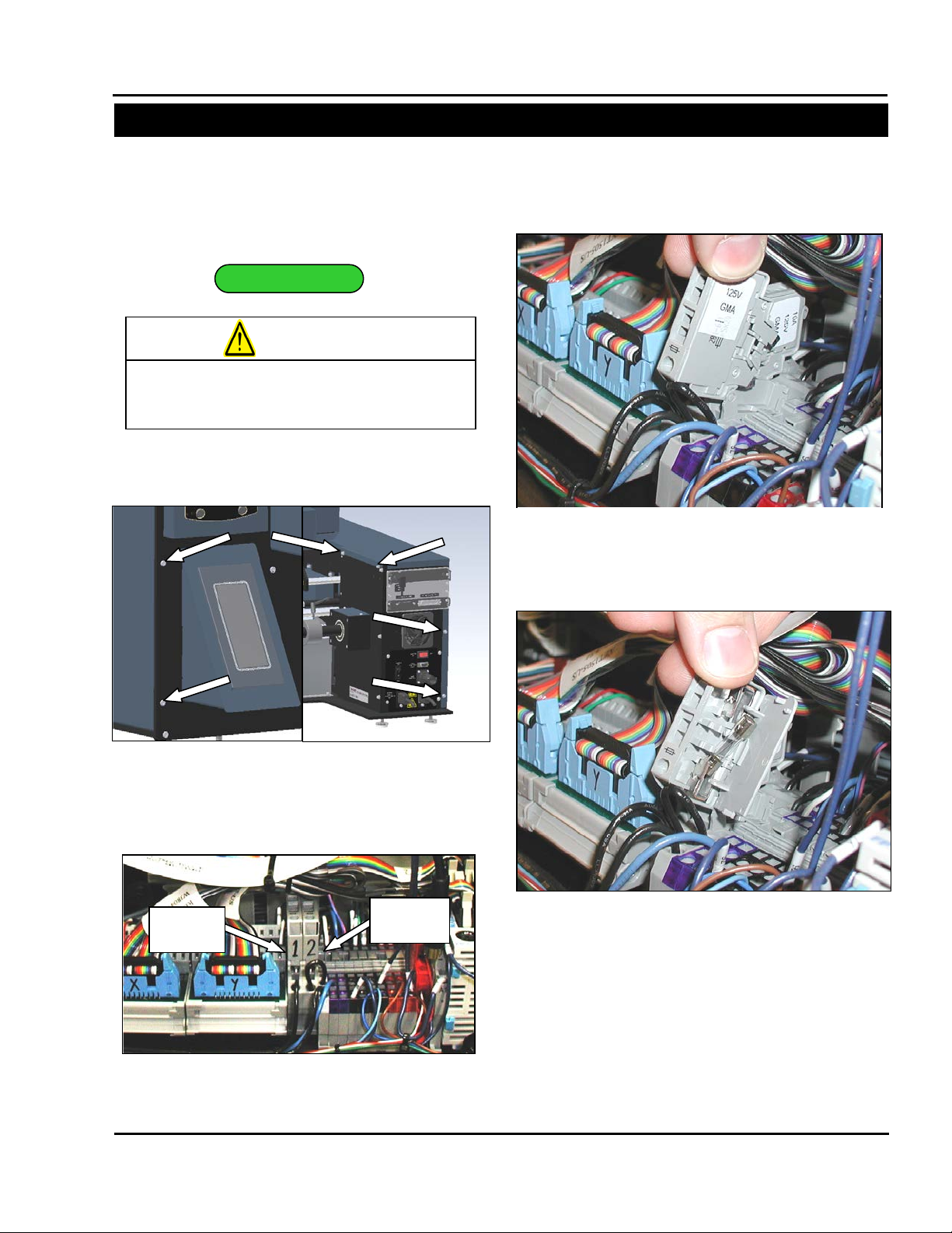
7. If the fuse is OK, check the wiring of TB1 and
TB2. Reconnect any loose wires. (Figure 3-5).
8. Connect power cords to the Sharp SX
and turn the bagger on.
USE EXTREM E CAUTION WHILE SERVICING A
DO NOT ATTEMPT TO SERVICE THE MACHINE
DURING NORMAL OPERATION. KEEP HANDS
WHEN TESTING ELECTRICAL COMPONENTS
WHILE POWER IS APPLIED TO T HE MACHINE,
9. Loc ate Red LED on the de fective drive (Figure
3-4).
Service and Maintenance Manual 3-2 960714-02B © 2007 I2407
TM
Bagger
10. If the LED is blinking, use the following
information to diagnose the problem.
• Is the LED blinking once?
This error code indicates t hat there is an open
or sporadic connection in one of the motor
wires. Check the wiring and ensure that the
connector screws are tight.
• Is the LED blinking twice?
This error code indica tes th at ther e is a s hort in
one of the motor lines . This can either occur in
the windings of the motor or be caused by
loose wiring.
1. Disconnect the motor from the drive at the
white 2x3 pin plug.
2. Check the motor and wiring for shorts.
Page 23
SX™
SECTION 3 – COMPONENT REPAIR
ELECTRICAL COMPONENTS
Figure 3-8. TM4500 Configuration
A
B C ADJUSTMENT
Figure 3-6. Load Plate Screws
Figure 3-7. TM4500 Drive locations
Pressure
Jaw
Film
Feed
PRESSURE JAW AND FILM FEED
MOTOR CONTROLLERS (con’t)
11. Refer to section on testing transformers to test
incoming voltage.
The TM4500 Stepper Drives are controlled by the
Aromat PLC and should be left at the factory
default settings. T he following steps will guide you
through resetting the drives to factory defaults.
1. Remove the four screws from the Load Plate
and set aside (Figure 3-6).
2. There are two identical TM4500 drives, the
Pressure Jaw motor controller is on t he lef t and
the Film Feed motor controller is on the right
(Figure 3-7).
3. Set Jumpers JP1, JP2 and JP3 so that the
jumpers covers pins 1 and 2 (Figure 3-8 A)
4. Adjust Kick Current POT (potentiometer) so
that arrow points to 100 (Figure 3-8 B).
5. Set jumper JP4 so that the jumper covers pins
2 and 3 (Figure 3-8 C).
6. Reattach Load Plate to front of machine with
screws and locking washers.
Service and Maintenance Manual 3-3 960714-02B © 2007 I2407
Page 24
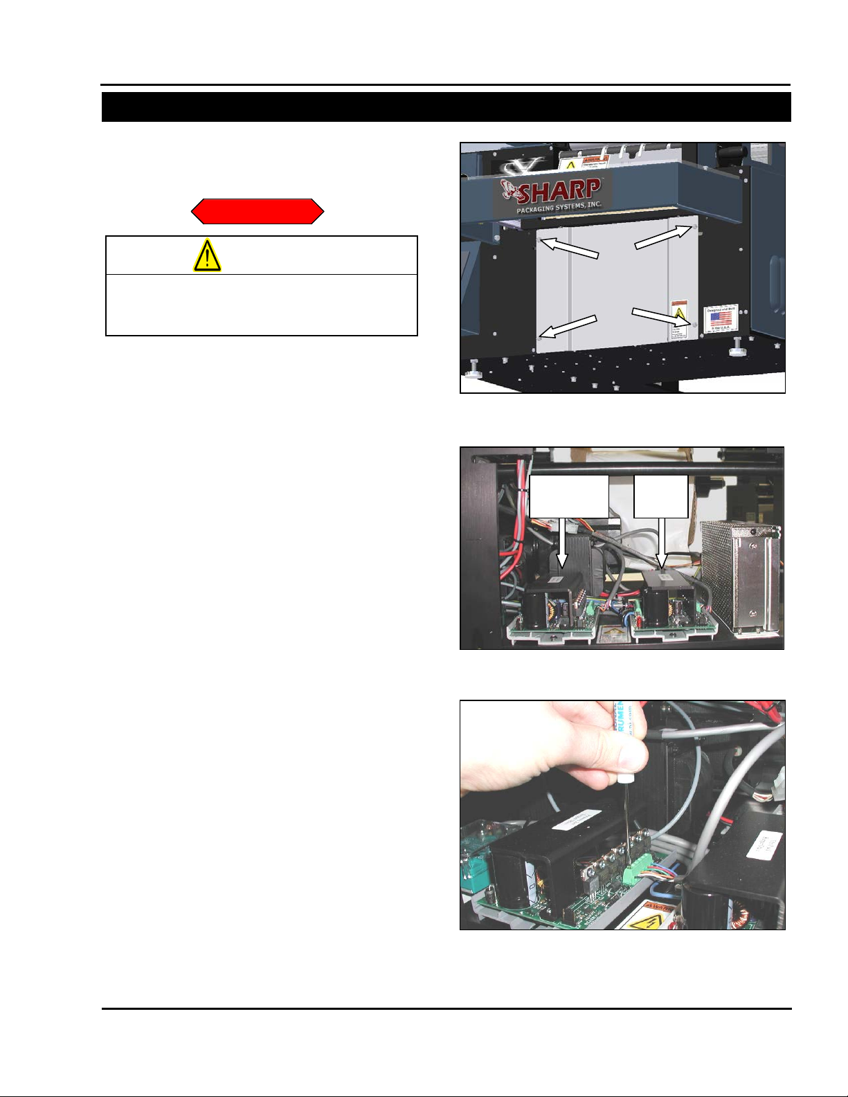
Figure 3-11 Green Connector Block
SX™
SECTION 3 – COMPONENT REPAIR
ELECTRICAL COMPONENTS
REPLACEMENT
Figure 3-10. TM4500 Drive locations
Pressure
Jaw
Film
Feed
Figure 3-9. Load Plate Screws
on the machine.
WARNING
PRESSURE JAW AND FILM FEED
MOTOR CONTROLLERS (con’t)
Always remove electrical power from the
1. Remove the four screws holding the Load
2. Loc ate the TM45 00 Steppe r Drive tha t requires
3. Unscrew all connections from the green
4. Slide drive out of grey DIN rail holder. The
5. Remove new drive from static bag.
prior to performing any maintenance
SX
Plate, set screws and Load Plate aside (Figure
3-9).
replacement. The Pressure Jaw motor
controller is on the lef t and the Fi lm Feed motor
controller is on the right (Figure 3-10).
connection blocks TB1 and TB2 (Figure 3-11).
drive is held in the DIN rail holder by friction
and requires considerable force to remove.
Brace the machine with one hand while firm ly
pulling the drive toward you with the other
hand.
Service and Maintenance Manual 3-4 960714-02B © 2007 I2407
Page 25
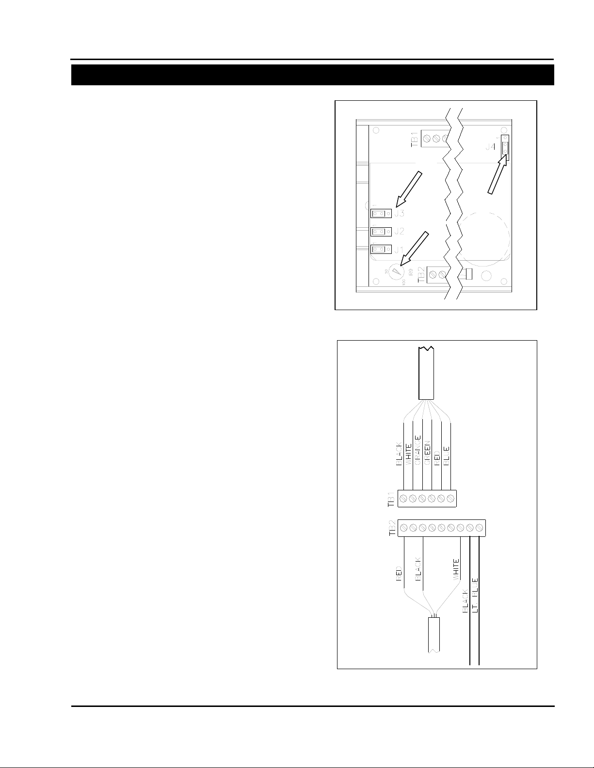
Figure 3-13. TM4500 Wiring Configuration
Figure 3-12. TM4500 Configuration
A
B
C
SX™
SECTION 3 – COMPONENT REPAIR
ELECTRICAL COMPONENTS
PRESSURE JAW AND FILM FEED
MOTOR CONTROLLERS (con’t)
6. Set jumpers JP1, JP2 and JP3 so that the
jumper covers pins 1 and 2 (Figure 3-12 A).
7. Set the POT so that the arrow points to 100
(Figure 3-12 B).
8. Set jumper JP4 so that the jumper c overs pins
2 and 3 (Figure 3-12 C).
9. O rientate drive so T B2 is on your left and slide
new drive into DIN rail holder. This will take
considerable force. Brace the machine with
one hand wile firml y pushing the new drive into
the DIN rail holder.
10. Reconnect all wires as they were con nected to
the previous drive (Figure 3-13).
11. Reattach Load Plate t o front of machine using
screws and locking washers.
Service and Maintenance Manual 3-5 960714-02B © 2007 I2407
Page 26
SX™
SECTION 3 – COMPONENT REPAIR
ELECTRICAL COMPONENTS
TESTING
Figure 3-14. Frame Cover Screws
Figure 3-16. Pivot Fuse Holder
Figure 3-17. Fuse Access Door
Figure 3-15. Fuse Locations
System
Fuse
Stepper
Fuse
on the machine.
WARNING
FUSES
The Sharp SX
protect the machinery from overloads. Fuses are
NOT intended to prot ect against electrocution and
are not considered a safety device.
Always remove electrical power from the
prior to performing any maintenance
SX
1. Remove Frame Cover Screws. There are six
screws to remove (Figure 3-14).
2. Remove Frame Cover and set aside.
3. Locate the two Fuses. (Figure 3-15)
TM
Bagger uses a series of fuses to
4. Pivot fuse holder to gain access to the Fuse
Access Door on the defective fuse.
5. Open Fuse Access Door and remove fuse
(Figure 3-17)
6. With a DVOM set to test for continuit y, touch the
black probe to one side of the fuse and the red
probe to the other side of the fuse. If the DVOM
does not indicate continuity, replace fuse.
Service and Maintenance Manual 3-6 960714-02B © 2007 I2407
Page 27
SX™
SECTION 3 – COMPONENT REPAIR
ELECTRICAL COMPONENTS
ADJUSTMENT
REPLACEMENT
Figure 3-18. Frame Cover Screws
Figure 3-19. Pivot Fuse Holder
Figure 3-20. Fuse Access Door
on the machine.
WARNING
FUSES (con’t)
There are no adjustments necessary on fuses.
A blown fuse can be an indic ation of a larger issue
with the electronics in t he Sharp SX
NOT REPLACE A BLOWN FUSE WITH A
LARGER AMPERAGE FUSE. If you continue to
blow fuses, troubleshoot other components to
discover problem.
Always remove electrical power from the
prior to performing any maintenance
SX
1. Remove Frame Cover Screws; there are six
screws to remove (Figure 3-18).
2. Loc ate the defective fus e. The 10 Amp system
fuse is on the left and the 5 amp stepper driv e
fuse is on the right.
3. Pivot fuse holder to gain access to the Fuse
Access Door (Figure 3-19).
4. Open Fuse Access Door and remove fuse
(Figure 3-20).
5. Replace with a 5x20mm fuse of the same
amperage.
6. Close ac cess door and pivot fuse holder back
into its home position.
7. Repl ace Frame Cover with sc rews and locking
washers.
TM
Bagger. DO
Service and Maintenance Manual 3-7 960714-02B © 2007 I2407
Page 28
TESTING
Figure 3-22. Motor Cover Front Screws
Figure 3-21. Motor Cover Rear Screws
SX™
SECTION 3 – COMPONENT REPAIR
ELECTRICAL COMPONENTS
24 VDC POWER SUPPLY
The Sharp SX
power supply for all sensors, relays and control
components. This section will explain how to
troubleshoot and if necessary, replace the power
supply.
The symptoms of a non-functioning Power Supply
are easy to spot. The “Bag Open Cage Fan” and
“Cabinet Cooling Fan” are not powered by the 24
VDC power supply. If when powering up a
machine, the fans can be heard running, but the
rest of the system is unresponsive, The Power
Supply is most likely defective. If a machine is
completely unresponsive, refer to the section on
checking and replacing fuses.
1. Plug machine in but do not turn on.
2. Remove any bags in the machine web path
and remove bag roll.
3. Rem ove the two rear screws a nd the two front
screws from the Motor Cov er (Figure 3-21 and
Figure 3-22).
4. Remove Motor Cover and set aside.
5. Loc ate the 24 VDC Po wer Sup ply.
Note: The Power Supply location changes
depending on your version of the Sharp SX
Bagger. The wiring however is exactly the
same.
TM
bagger uses a single 24 VDC
TM
Service and Maintenance Manual 3-8 960714-02B © 2007 I2407
Page 29
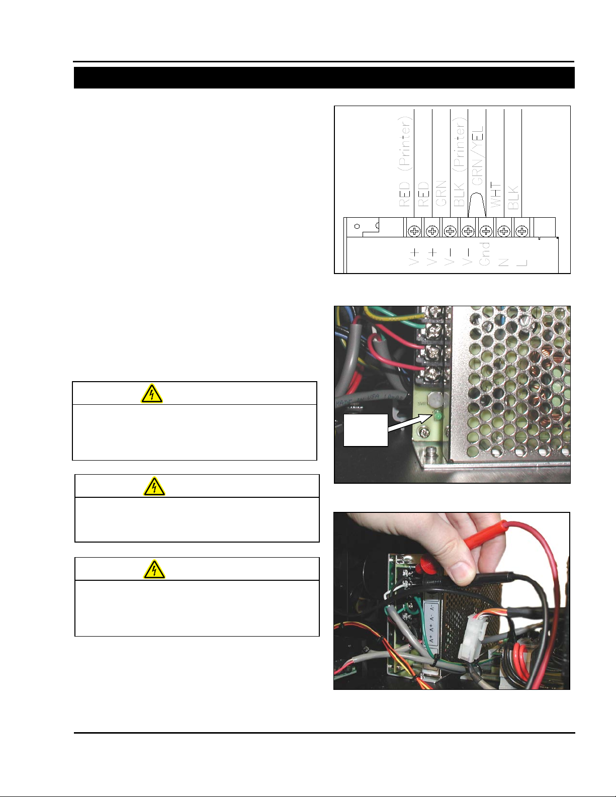
Figure 3-23. 24 VDC Power Suppl y
Figure 3-24. Power Supply Status LED
Status
LED
Figure 3-25. Probing 120 VAC on Power Supply
MACHINE WHILE POWER IS APPLIED.
CAUSE SERIOUS INJURY.
WARNING
AND ARMS CLEAR OF MOVING PARTS.
WARNING
USE PROPER TROUBLESHOOTING
TECHNIQUES TO AVOID ELECTRICAL SHOCK.
WARNING
SX™
SECTION 3 – COMPONENT REPAIR
ELECTRICAL COMPONENTS
24 VDC POWER SUPPLY (con’t)
6. Visua lly check wir ing on Power S upply. (Figure
3-23)
Note: The “V-“connection on the Power Supp ly
is connected to “Earth Ground ” by a short wire.
Also, lines labeled with “Printer” are only
present on baggers with a printer.
7. If there is a noticeable problem with the wiring
of the Power Supp ly, refer to the re placement
section for directions to rewire power supply.
8. T urn ON device using the power switch in the
back of the machine.
9. Check that the Green Status LED is
illuminated. (Figure 3-24) If it is, you may
proceed to step 13.
10. Set your DVOM to a range capable of testing
120 Volts AC.
USE EXTREM E CAUTION WHILE SERVICING A
UNEXPECTED MACHINE STARTUP CAN
DO NOT ATTEMPT TO SERVICE THE MACHINE
DURING NORMAL OPERATION. KEEP HANDS
WHEN TESTING ELECTRICAL COMPONENTS
WHILE POWER IS APPLIED TO T HE MACHINE,
11. Probe the L and N contacts on the Power
Supply with a DVOM; it should display
approximately 120 VAC (Figure 3-25).
Service and Maintenance Manual 3-9 960714-02B © 2007 I2407
Page 30
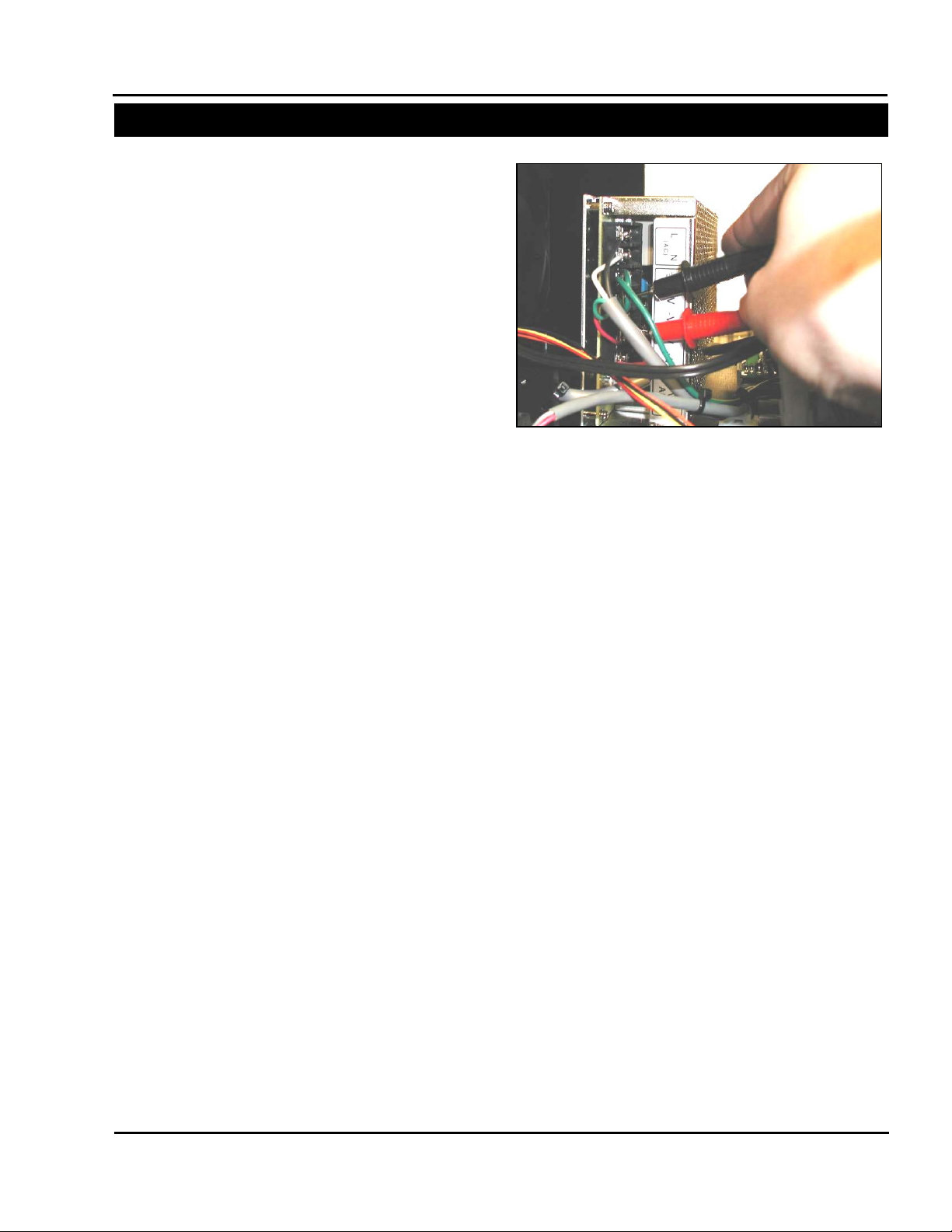
Figure 3-26. Probing “V-“ and “V+”
SX™
SECTION 3 – COMPONENT REPAIR
ELECTRICAL COMPONENTS
24 VDC POWER SUPPLY (con’t)
12. If 0 VAC is displayed, there is no power
reaching the Power S upply. Check the 10 amp
system fuse and ensure there are no loose
wires.
13. Set your DVOM to a range capable of
measuring 24 VDC. Prob e bet ween th e “ V-“and
“V+” contacts on the Power Supply (Figur e 3-
26).
14. If 0 Volts DC is displayed, then the Power
Supply is defective. Ref er to the Replacement
section.
Service and Maintenance Manual 3-10 960714-02B © 2007 I2407
Page 31

ADJUSTMENT
Figure 3-29. Voltage Selector Switch
Figure 3-27. Motor Cover Rear Screws
Figure 3-28. Motor Cover Front Screws
SX™
SECTION 3 – COMPONENT REPAIR
ELECTRICAL COMPONENTS
24 VDC POWER SUPPLY (con’t)
The Sharp SX
user adjustable setti ngs. These settings are set at
the factory and do not require regular adjustment.
The following steps will guide you through setting
the Power Supply to the factory defaults.
1. Rem ove the two rear screws a nd the two front
screws from the Motor Cov er (Figure 3-27 and
Figure 3-28).
TM
Bagger’s Power Supply has two
2. Loc ate the 24 VDC Po wer Sup ply.
Note: The power supply location changes
depending on your version of the Sharp SX
TM
Bagger. The wiring however is exactly the
same
.
3. Loc ate the red Switch on t he side of the Power
Supply. (Figure 3-29).
4. Set the Voltage Selector Switch to 115V.
Note: If your region uses 230 VAC as the
standard voltage, a step-down transformer is
required. This will lower the voltage entering
the machine to 115 VAC. Set the Voltage
Selector Switch to 115V regardless of your
region.
Service and Maintenance Manual 3-11 960714-02B © 2007 I2407
Page 32

Figure 3-30. Adjusting Power Supply Voltage
Figure 3-31. Testing 24 VDC on Power Supply
E WHILE POWER IS APPLIED.
UNEXPECTED MACHINE STARTUP CAN
CAUSE SERIOUS INJURY.
WARNING
AND ARMS CLEAR OF MOVING PARTS.
WARNING
USE PROPER TROUBLESHOOTING
TECHNIQUES TO AVOID ELECTRICAL SHOCK.
WARNING
SX™
SECTION 3 – COMPONENT REPAIR
ELECTRICAL COMPONENTS
24 VDC POWER SUPPLY (con’t)
5. Plug the Sharp SX
machine on.
USE EXTREM E CAUTION WHILE SERVICING A
MACHIN
DO NOT ATTEMPT TO SERVICE THE MACHINE
DURING NORMAL OPERATION. KEEP HANDS
WHEN TESTING ELECTRICAL COMPONENTS
WHILE POWER IS APPLI ED TO THE M ACHINE,
6. Set your DVOM to a range capable of
measuring 24 VDC.
7. W ith one hand, position a small screwdriver on
the voltage adjustment POT (Figure 3-30).
8. Place the black probe on the “V-“contact and
the red probe on the “V+” contact (Figure 3-31).
9. Adjust the POT until your DVOM reads 24.0
VDC +/- .5.
Note: Depending on your v ersion of the Sharp
TM
Bagger, the Power Supply POT may be
SX
difficult to reach. If this is the case, measure
the voltage, then set the probes aside and
adjust the voltage with a small screwdriver.
Repeat until DVOM indicates 24.0 VDC.
10. Replace Motor Cover us ing s crews and loc king
washers.
TM
Bagger in and turn the
Service and Maintenance Manual 3-12 960714-02B © 2007 I2407
Page 33

REPLACEMENT
Figure 3-32. Motor Cover Rear Screws
Figure 3-33. Motor Cover Front Screws
Figure 3-34. Power Supply screw locations
Figure 3-35. Voltage Selector Switch
on the machine.
WARNING
SX™
SECTION 3 – COMPONENT REPAIR
ELECTRICAL COMPONENTS
24 VDC POWER SUPPLY (con’t)
1. T urn off the Shar p SX
all power cords.
Always remove electrical power from the
prior to performing any maintenance
SX
2. Rem ove the two rear screws a nd the two front
screws from the Motor Cov er (Figure 3-32 and
Figure 3-33).
TM
Bagger and disconnec t
3. Disconnect all wires from the Power Supply.
4. Remove the three screws holding the Power
Supply to the frame. (Figure 3-34).
5. Remove the defective Power Supply and set
aside.
6. W ith new power supp ly, check that the Voltage
Selector Switch is set to 115 VAC (Figure 3-
35).
Note: If your region uses 230 VAC as the
standard voltage, a step-down transformer is
required. This will lower the voltage entering
the machine to 115 VAC. Set the Voltage
Selector Switch to 115V regardless of your
region.
Service and Maintenance Manual 3-13 960714-02B © 2007 I2407
Page 34

Figure 3-36. 24 VDC Power Suppl y
SX™
SECTION 3 – COMPONENT REPAIR
ELECTRICAL COMPONENTS
24 VDC POWER SUPPLY (con’t)
7. Reconnect all wires to the Power Supply
(Figure 3-36).
8. Place new Power Supply in the Sharp SX
Bagger in the sam e location and or ientation as
the old power supply.
9. Us e screws from old Power Suppl y and secure
new Power Supply to the frame.
10. Reconnect power cord to the Sharp SX
Bagger and turn machine on.
11. Set your DVOM to a range capable of
measuring 24 VDC.
TM
TM
Service and Maintenance Manual 3-14 960714-02B © 2007 I2407
Page 35

Figure 3-38. Testing 24 VDC on Power Supply
Figure 3-37. Adjusting Power Supply Voltage
SX™
SECTION 3 – COMPONENT REPAIR
ELECTRICAL COMPONENTS
24 VDC POWER SUPPLY (con’t)
12. With one hand, position a sm all screwdriver on
the voltage adjustment POT (Figure 3-37).
13. Place the black probe on the “V-“contact and
the red probe on the “V+” contact (Figure 3-38).
14. Adjust the POT until your DVOM reads 24.0
VDC.
Note: Depending on your v ersion of the Sharp
TM
Bagger, the Power Supply POT may be
SX
difficult to reach. If this is the case, measure
the voltage, then set the probes aside and
adjust the voltage with a small screwdriver.
Repeat until DVOM indicates 24.0 VDC.
15. Replace Motor Cover.
Service and Maintenance Manual 3-15 960714-02B © 2007 I2407
Page 36

TESTING
Figure 3-39. Frame Cover Screws
Figure 3-42. Remove three spade connectors
Figure 3-XX Mandrel Support screws
Figure 3-41. Mandrel Support Plate Bottom
Screws
Plate
screws
Mandrel
screws
Figure 3-40. Mandrel Support Screws
SX™
SECTION 3 – COMPONENT REPAIR
ELECTRICAL COMPONENTS
LINE FILTER
This procedure requires working with exposed
high voltages. Only qualifie d personnel familiar
with electrical safety should perform this
procedure.
1. Remove all power to the machine.
2. Remove the six screws holding the Frame
Cover. Set screws and Frame Cover aside
(Figure 3-39).
3. Remove any bags on a roll from machine.
4. Rem ove the seven scr ews holding th e Mandrel
Support Plate, set screws and plate aside
(Figure 3-40 & Figure 3-41).
Note: There are seven screws holding the
Mandrel Support Plate. Use care when
removing bottom scr ews and never work on an
unstable platform.
5. Detach the three spade connectors from the
Line Filter (Figure 3-42).
Support
Service and Maintenance Manual 3-16 960714-02B © 2007 I2407
Page 37

GRN-Earth
BLK-L
BLU-N
Figure 3-43. Wire colors and locations
Figure 3-44. Mandrel Support Plate alignment
Recessed
Circle
MACHINE WHILE POWER IS APPLIED.
STARTUP CAN
CAUSE SERIOUS INJURY.
WARNING
AND ARMS CLEAR OF MOVING PARTS.
WARNING
TECHNIQUES TO AVOID ELECTRICAL SHOCK.
WARNING
on the machine.
WARNING
SX™
SECTION 3 – COMPONENT REPAIR
ELECTRICAL COMPONENTS
LINE FILTER (con’t)
6. Reconnect the power cord to the machine.
Note: There will be exposed 120 VAC. Use
extreme caution when working with expos e d wires .
USE EXTREM E CAUTION WHILE SERVICING A
UNEXPECTED MACHINE
DO NOT ATTEMPT TO SERVICE THE MACHINE
DURING NORMAL OPERATION. KEEP HANDS
WHEN TESTING ELECTRICAL COMPONENTS
WHILE POWER IS APPLIED TO T HE MACHINE,
USE PROPER TROUBLESHOOTING
7. With a DVOM configured to m easure 120 V AC,
contact the red probe to the L pin and th e Blac k
probe to the N pin. If 120 VAC is not indicated,
the Line Filter is defective or no power is
reaching the machine.
8. Unplug machine from any power sources.
Always remove electrical power from the
9. Rec onnect spade connectors to th e Line Filter
10. Replace the seven screws for the Mandrel
prior to performing any maintenance
SX
(Figure 3-43).
Support Plate but do not tighten down.
11. Hand tighten the four top s crews, ens uring that
the end of the Material Roll Mandrel is sitting
inside the recessed circle of the Mandrel
Support Plate (Figure 3-44).
12. Tighten all screws with an Allen Wrenc h.
Service and Maintenance Manual 3-17 960714-02B © 2007 I2407
Page 38

ADJUSTMENT
REPLACEMENT
Figure 3-45. Frame Cover Screws
Figure 3-48. Remove three spade connectors
Mandrel
screws
Figure 3-46. Mandrel Support screws
Figure 3-47. Mandrel Support Plate Bottom
Screws
Plate
screws
on the machine.
WARNING
SX™
SECTION 3 – COMPONENT REPAIR
ELECTRICAL COMPONENTS
LINE FILTER (con’t)
There are no adjustments necessary on the Line
Filter.
Always remove electrical power from the
1. Remove the six screws holding the Frame
2. Rem ove the seven scr ews holding th e Mandrel
3. Remove the three spade connectors from the
prior to performing any maintenance
SX
Cover, set screws and Frame Cover aside
(Figure 3-45).
Support Plate, set screws and plate aside
(Figure 3-46 & 3-47).
Note: There are seven screws holding the
Mandrel Support Plate. Use care when
removing bottom scr ews and never work on an
unstable platform.
Line Filter (Figure 3-48).
Support
Service and Maintenance Manual 3-18 960714-02B © 2007 I2407
Page 39

Module
Screws
Figure 3-49. Line Filter Screws
GRN-Earth
BLK-L
BLU-N
Figure 3-50. Wire colors and locations
Figure 3-51. Mandrel Support Plate alignment
Recessed
Circle
SX™
SECTION 3 – COMPONENT REPAIR
ELECTRICAL COMPONENTS
LINE FILTER (con’t)
4. Rem ove the two screws h olding the Line Filter
to the Rear Face Plate (Figure 3-49).
5. Remove Line Filter.
6. Orientate new module so the two spade
connectors are towards the top.
7. Refasten new module to frame with screws
from defective module.
8. Reattach the three connector wires, Earth
(Green) on the left, Neutral (Blue) on the top
right, and Live (Black ) on the bottom (Figure 3-
50).
9. Replace the seven screws for the Mandrel
Support Plate but do not tighten down.
10. Hand-tighten the four top s crews, ensur ing that
the end of the Material Roll Mandrel is sitting
inside the recessed circle of the Mandrel
Support Plate (Figure 3-50).
11. Tighten all screws with an Allen wrench.
12. Replace Frame Cover with screws and lock
washers.
Service and Maintenance Manual 3-19 960714-02B © 2007 I2407
Page 40

TESTING
ADJUSTMENT
Figure 3-52. Frame Cover Screws
Figure 3-53. Main Red Switch location
Main
Switch
5A Fuse
10A Fuse
Figure 3-54. Fuse Locations
on the machine.
WARNING
SX™
SECTION 3 – COMPONENT REPAIR
ELECTRICAL COMPONENTS
MAIN POWER SWITCH (RED)
Always remove electrical power from the
1. Remove the six screws holding the Frame
2. T urn the switch to the OFF posit ion (Figure 3-
3. Configure your DVOM to test for continuity,
4. Turn the switch to the ON position.
5. Configure your DVOM to test for continuity,
6. If the Main Power Switch is not found to be
There are no adjustments necessary on the Main
Power Switch.
prior to performing any maintenance
SX
Cover, set screws and Frame Cover aside
(Figure 3-52).
53).
contact one probe to th e 5 A F use a nd the other
probe to the 10A Fuse (F igure 3-54) It should
NOT read continuity.
contact one probe to th e 5 A F use and the other
probe to the 10A Fuse ( Figure 3-54). It should
read continuity. If it does not, ensure there are
no loose wires. If the wiring is not defective,
replace the Main Power Switch.
defective, troubleshoot the Line Filter and fuses
if you haven’t already done so.
power
Service and Maintenance Manual 3-20 960714-02B © 2007 I2407
Page 41

REPLACEMENT
Figure 3-55. Frame Cover Screws
Figure 3-56. Plastic divider locat ion
Plastic divider
Figure 3-57. Back of Main Power Switch
Retaining
Clips
on the machine.
WARNING
SX™
SECTION 3 – COMPONENT REPAIR
ELECTRICAL COMPONENTS
MAIN POWER SWITCH (RED) (con’t)
Always remove electrical power from the
1. Remove the six screws holding the Frame
2. Rem ove the seven scr ews holding th e Mandrel
3. Remove the three spade connectors from the
4. The switch is held in place by four retaining
5. O rientate switch so t he plastic divi der is on the
6. Reconnect the three spade connectors. The
prior to performing any maintenance
SX
Cover. Set screws and Frame Cover aside
(Figure 3-55).
Support Plate, set screws and plate aside.
back of the Main Power Switch (Figure 3-56).
clips, squeeze clips on eith er side of the switch
while firmly pushing switch out of Rear Face
Plate (Figure 3-57).
left side as you are look ing at the back of the
switch as you snap it into the Rear F ace Plate.
Snap replacement switch into Rear Face Plate.
Light Blue wire is attached to the contact
furthest from you; the two Black wires are
attached to the remaining contacts.
Service and Maintenance Manual 3-21 960714-02B © 2007 I2407
Page 42

TESTING
Figure 3-59. Motor Cover Rear Screws
Figure 3-58. Motor Cover Front Screws
Figure 3-60. Load Plate Screws
on the machine.
WARNING
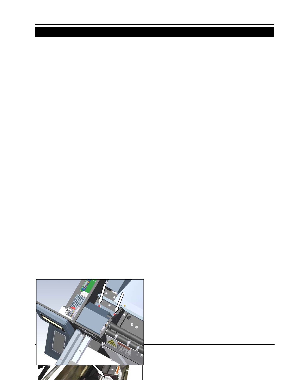
Figure 3-61. Transformer locations for the SX
Stepper Drive
Seal Wire
Solid State Relay
SX™
SECTION 3 – COMPONENT REPAIR
ELECTRICAL COMPONENTS
TRANSFORMERS
The Sharp SX
transformers. One is used for the Seal Wire and the
other is used for the two TM4500 stepper drives.
They are each 0.365 KVA transformers with a
120(P):28(S) voltage rat io. Only replace with equal
or greater KVA rating and same voltage ratio.
Always remove electrical power from the
prior to performing any maintenance
SX
1. Rem ove the two rear screws a nd the two front
screws holding the Motor Cover. (Figure 3-58
and Figure 3-59)
TM
Bagger uses two “Step-Down”
2. Remove Motor Cover and set aside.
3. Remove the four screws holding the Load
Plate, set screws and Load Plate aside (Figure
3-60.)
4. Locate the transformer you wish to
troubleshoot and proceed to that section
(Figure 3-61).
Note: Transformer locations will change
depending on your version of the SX. The
Stepper Drive transformer’s wires terminate in
a terminal block. T he Seal Wire transformer is
connected to the Solid State Relay and Seal
Wire.
1108 and 1109
Service and Maintenance Manual 3-22 960714-02B © 2007 I2407
Page 43

Figure 3-63. Left side Seal Bar connection
Figure 3-64. Probing right side of Seal Wire
Figure 3-62. Testing pin 2 of Solid State Relay
SX™
SECTION 3 – COMPONENT REPAIR
ELECTRICAL COMPONENTS
TRANSFORMERS (con’t)
Seal Wire Transformer
1. Rem ove clear plastic covering over Solid State
Relay.
2. Set your DVOM to test for continu ity. With the
Black probe, contact the B lue terminal block in
the electrical area, with the Red prob e, contact
pin 2 of the Solid State Relay. (Figure 3-62)
Your DVOM should indicate continuity. If it
does not, check the transformer wiring. If the
wiring is correct, the transformer is defective
and will require replacement.
3. Rem ove the Left scr ew holding the Red wire to
the Seal Wire. Pull wire away from contact
(Figure 3-63).
4. W ith a DVOM set to t est for continuit y, contact
one probe to the loose Red wire you just
disconnected, and contact the other probe to
the right screw holding the other Red wire to
the Seal Wire (Figure 3-64).
5. T he DVOM will indica te co ntinuit y, if it does not
the Seal Wire Transformer is defective and
must be replaced.
6. If the transformer is not defective, troublesho ot
the Solid State Relay and the Seal Wire.
Service and Maintenance Manual 3-23 960714-02B © 2007 I2407
Page 44

ADJUSTMENT
Figure 3-66 Testing two front terminal blocks
SX™
SECTION 3 – COMPONENT REPAIR
ELECTRICAL COMPONENTS
Figure 3-65 Print Head Stepper Drive
Stepper
Terminal
MACHINE WHILE POWER IS APPLIED.
UNEXPECTED MACHINE STARTUP CAN
CAUSE SERIOUS INJURY.
WARNING
AND ARMS CLEAR OF MOVING PARTS.
WARNING
USE PROPER TROUBLESHOOTING
TECHNIQUES TO AVOID ELECTRICAL SHOCK.
WARNING
TRANSFORMERS (con’t)
Stepper Drive Transformer
1. Locate the two terminal blocks with the Red
wires connected to the transformer (Figure 3-
65).
Note: Location and orientation will vary
depending on model.
2. W ith a DVOM set to test for continuity, probe
the two front terminal blocks and the two rear
terminal blocks . Both s hould in dic at e c ont inu ity.
(Figure 3-66).
3. Rec onnec t machine to po w er and turn m ac hine
on.
USE EXTREM E CAUTION WHILE SERVICING A
DO NOT ATTEMPT TO SERVICE THE MACHINE
DURING NORMAL OPERATION. KEEP HANDS
WHEN TESTING ELECTRICAL COMPONENTS
WHILE POWER IS APPLIED TO T HE MACHINE,
4. Set your DVOM measure 120 VAC. Probe the
two terminal blocks connected to the Black
wires from the transform er. The DVOM should
indicate 120 VAC. If it does not, troubleshoot
the wiring from the main DIN Rail (located
under the frame guard behind the display,
where terminals, PLC, and fuse blocks are
snapped onto).
There are no adjustments necessary on
transformers.
Transformer
Note: Electrical assembly isolated for clarity
Service and Maintenance Manual 3-24 960714-02B © 2007 I2407
Page 45

SX™
SECTION 3 – COMPONENT REPAIR
ELECTRICAL COMPONENTS
REPLACEMENT
Figure 3-67. Motor Cover Rear Screws
Figure 3-68. Motor Cover Front Screws
Figure 3-69. Transformer locations on an 1108 or
Stepper Drive
Seal Wire
Figure 3-70. Frame Cover Screws
on the machine.
WARNING
TRANSFORMERS (con’t)
Always remove electrical power from the
1. Remove the two rear and two front screws
prior to performing any maintenance
SX
holding the Motor Cover on. Set screws and
Motor Cover aside (Figures 3-67 & 3-68)...
2. Locate transformer that requires replacement
(Figure 3-70).
1109
3. If you are replacing the Seal W ire Transformer
Remove the six screws holding the Frame
Cover, set screws and Frame Cover aside
(Figure 3-70).
Service and Maintenance Manual 3-25 960714-02B © 2007 I2407
Page 46

SX™
SECTION 3 – COMPONENT REPAIR
ELECTRICAL COMPONENTS
Figure 3-71. Load Plate Screws
Figure 3-72 Transformer Bolt Locations
TRANSFORMERS (con’t)
4. If you are replacing the Stepper Drive
Transformer, remove the four screws holding
the Load Plate, set screws and Load Plate
aside (Figure 3-71).
5. Foll ow each of the four wir es coming out of the
Transformer and note the ir locations and color.
You may want to write this information down.
Note: The wiring diagram i n this ma nual can b e
used to determine transformer connections;
however it is easier to write this information
down.
6. Disconnect the ends of each wire and feed
them back through any Wire Troughs or Wire
Ties. You will prob ably have to cut a few W ire
Ties to do this.
7. Remove the four screws holding the
Transformer to the Base Plate (Figure 3-72).
8. Note the orientation of the Red and Black
wires. Remove transformer.
9. With the replacement Transformer, orientate
Red and Black wires so that the y are facing t he
same direction as the old Transformer.
10. Fasten Transform er to Base Plate wit h the four
screws from the old Transformer.
11. Reconnect the two Red and two B lack wires to
their previous locations.
Note: If replacing the Seal Wire Transformer,
you will have to terminate t he Red wires with a
Ring Terminal of similar size.
12. Replace Frame Cover and Motor Cover using
screws and locking washers.
Service and Maintenance Manual 3-26 960714-02B © 2007 I2407
Page 47

SX™
SECTION 3 – COMPONENT REPAIR
ELECTRICAL COMPONENTS
REPLACEMENT
ADJUSTMENT
TESTING
Figure 3-73. Frame Cover Screws
Figure 3-75 Removing PLC
Figure 3-74 PLC Connections
X-1
X-2
Y-1
Y-2
PLC
Power
Display
on the machine.
WARNING
AROMAT PLC
The Sharp SX
FPΣ PLC. This is an NPN (sinking outputs) device
with 16 inputs and 16 outputs.
Check that there is power reaching the PLC by
checking for green lights o n top of the PLC. If there
are no lights, check the PLC Power connector, or
troubleshoot the 24VDC Po wer Suppl y. If there is a
red blinking light on the PLC, the PLC has faulted,
contact Sharp Packaging.
There are no adjustments necessary on the Aromat
PLC
Always remove electrical power from the
prior to performing any maintenance
SX
1. Remove the six screws holding the Frame
Cover. Set screws and Frame Cover aside
(Figure 3-73).
2. Rem ove all connections fr om the Aromat PLC.
There are six connec tions: Power, Displa y and
four ribbon cables. Note where the ribbon
cables are connected to the PLC (Figure 3-74).
3. Us ing a small flat screwdriv er, pu ll the b lue DIN
rail release tab toward you and pivot the PLC
up and back (Figure 3-75).
4. Remove old Aromat PLC and set aside.
5. Place new Aromat PLC onto DIN rail with the
circular plug closest to you.
6. Reconnect all wires (Figure 3-74).
TM
Bagger is controlled by an Aromat
Service and Maintenance Manual 3-27 960714-02B © 2007 I2407
Page 48

SX™
SECTION 3 – COMPONENT REPAIR
ELECTRICAL COMPONENTS
REPLACEMENT
ADJUSTMENT
TESTING
Figure 3-76. Frame Cover Screws
Figure 3-78. Removing PLC
Figure 3-77. PLC Connections
on the machine.
WARNING
AROMAT PLC BATTERY
The Aromat PLC battery is a 1.5 VDC “Button”
battery. It is used by the PLC to retain user
settings. The average lifetime of the PLC batter y is
two years. It is suggested that you replace the
battery annually.
Note: Not all m achines ar e equipp ed wit h a P LC
Battery. If no battery is present in your PLC, you
do not have to install one.
There are no testing procedures to be performed
on the Aromat PLC battery.
There are no adjustments necessary on the Aromat
PLC battery.
Always remove electrical power from the
1. Remove the six Frame Cover screws (Figure 3-
2. Remove Frame Cover and set aside.
3. Disconnect the touch screen communications
4. Using a small flat screwdriver, pull the blue DIN
5. Remove the PLC from the DIN Rail.
prior to performing any maintenance
SX
76).
cable and the power wiring connector (Figure 3-
77).
rail release tab toward you and pivot the PLC up
and back (Figure 3-78).
Service and Maintenance Manual 3-28 960714-02B © 2007 I2407
Page 49

SX™
SECTION 3 – COMPONENT REPAIR
ELECTRICAL COMPONENTS
Figure 3-80. PLC Battery Connector
Battery
Plug
Figure 3-79. PLC Battery Location
Battery
Cover
Figure 3-81. PLC Connections
PLC
Power
Display
AROMAT PLC BATTERY (con’t)
6. Rem ove the batt er y cover by lif ting the edge of the
cover and remove the cover (Figure 3-79).
7. Remove replacement battery from any packaging.
Note: To avoid losing any data, connect the ne w
battery to the PLC within 30 seconds of
disconnecting the old one.
8. Dis connect old PLC battery wiring plug (Fig ure 3-
80).
9. Install the new battery and connect the wiring plug.
Note: the plug is keyed an d can only be installed
in the correct orientation.
10. Snap the battery cover back into place.
11. Install the PLC onto the din rail.
12. Reconnect the touch screen communications
cable and the power wiring (Figure 3-81).
13. Replace Frame Cover; there are six screws with
locking washers to replace.
Service and Maintenance Manual 3-29 960714-02B © 2007 I2407
Page 50

SX™
SECTION 3 – COMPONENT REPAIR
ELECTRICAL COMPONENTS
TESTING
Figure 3-83. Measuring 24 VDC on Display
Figure 3-82. Frame Cover Screws
MACHINE WHILE POWER IS APPLIED.
UNEXPECTED MACHINE STARTUP CAN
CAUSE SERIOUS INJURY.
WARNING
AND ARMS CLEAR OF MOVING PARTS.
WARNING
USE PROPER TROUBLESHOOTING
TECHNIQUES TO AVOID ELECTRICAL SHOCK.
WARNING
COLOR TOUCH SCREEN
The Sharp SX
touch sensitive user interface. The screen
interfaces with the Arom at PLC to provide the user
with setup functions and status information.
1. If the displa y does not tur n on with the m achine
or it turns on but no thing is displa yed, proceed
to the “Power Problem” section on the next
page. If “ERRF” is displayed in the corner,
proceed to the “Communication Problem”
section on the nex t page. If “Screen No . Error”
is displayed proceed to the “Program Problem”
on the next page.
USE EXTREM E CAUTION WHILE SERVICING A
DO NOT ATTEMPT TO SERVICE THE MACHINE
DURING NORMAL OPERATION. KEEP HANDS
WHEN TESTING ELECTRICAL COMPONENTS
WHILE POWER IS APPLIED TO T HE MACHINE,
TM
bagger includes a three color,
1. Remove the six screws holding the Frame
Cover, set screws and Frame Cover aside
(Figure 3-82).
2. W ith a Digital Vo lt/Ohm Meter (DVOM) set to a
range capable of measuring 24VDC, contact
the red probe to the 92 connection and the
black probe to the 91 connection (Figure 3-83).
3. If 24 VDC is not displayed, troubleshoot the
wiring between the power terminal blocks and
the display. If 24VDC is displayed, the displa y
is defective and will require replacement.
Service and Maintenance Manual 3-30 960714-02B © 2007 I2407
Page 51

SX™
SECTION 3 – COMPONENT REPAIR
ELECTRICAL COMPONENTS
92
91
BRO - ORNG - GRN
Figure 3-84. Display Connections
ADJUSTMENT
REPLACEMENT
Figure 3-85. Frame Cover Screws
on the machine.
WARNING
COLOR TOUCH SCREEN (con’t)
Communications Problem
1. Inspect Data Cable connection with PLC.
Ensure that the cable is pus hed all the wa y into
the socket on the PLC
2. Check that the wiring in the Display Plug is
correct and securel y screwed down (Figure 3-
84).
3. Check that the PLC has power by looking for
any illuminated lights o n top of the PLC. If the
PLC is not receiving po wer, ref er to the Arom at
PLC Section.
4. Display is defective.
Program Problem
A Screen No. Error occurs when the PLC requests
a screen number that is not programmed into the
display. T his typical ly occurs when the PLC B atter y
loses its charge. In th is case, the PLC will require
reprogramming.
There are no adjustm ents necessary on the Color
Touch Screen.
Note: The replacement C ol or T ouc h Scr ee n wi ll
require reprogramming if not obtained from
Sharp Packaging.
Always remove electrical power from the
1. Remove the six screws holding the Frame
prior to performing any maintenance
SX
Cover, set screws and Frame Cover aside
(Figure 3-85).
Service and Maintenance Manual 3-31 960714-02B © 2007 I2407
Page 52

SX™
SECTION 3 – COMPONENT REPAIR
ELECTRICAL COMPONENTS
92
91
Com Cable
Figure 3-86. Display Connections
Screws
Figure 3-87. Touch Screen Housing Scr ews
Screws
Figure 3-88. Display Screws
Figure 3-89. Reattach Retaining Clips
Clip
COLOR TOUCH SCREEN (con’t)
2. Unpl ug com m unications ca ble fr om display and
unscrew the power connections (Figure 3-86).
3. Remove the four screws holding the Touch
Screen Housing (Figure 3-87).
4. Pul l Touch Screen Ho using off Fr ont Plate and
place on a table, Touch Screen side down.
Note: Do not place display on any harsh
surfaces as this will scratch the screen.
5. Loos en th e scr ews on the f our cl ips hold ing t he
Touch Screen. Remove clips from Touch
Screen (Figure 3-88).
6. Remove the Touch Screen from the housing.
7. Ins ert new Touch Scree n into housing; position
Touch Screen so that the connections will be
on top when reinserted into Front Plate.
8. Reattach retaining clips to Touch Screen
(Figure 3-89).
9. Tighten the screws on the four retaining clips.
10. Reattach Touch Screen Ho using to Front Plate
with the four screws.
11. Reconnect Power and Communications Cable.
12. Replace Frame Cover.
Service and Maintenance Manual 3-32 960714-02B © 2007 I2407
Page 53

SX™
SECTION 3 – COMPONENT REPAIR
ELECTRICAL COMPONENTS
TESTING
ADJUSTMENT
REPLACEMENT
Figure 3-90. Motor Cover Rear Screws
Figure 3-91. Motor Cover Front Screws
Figure 3-92. Outside Cover - Right Screws
on the machine.
WARNING
COOLING FAN
Check that all con nec ti ons to t h e f an are c o nnec t ed
and secure.
There are no adjustments necessary on the
Cooling Fan.
Always remove electrical power from the
1. Remove the two rear scre ws and the two front
2. Remove Motor Cover and set aside.
3. Rem ove the Outside Cover – Right (Figure 3-
prior to performing any maintenance
SX
screws from the Motor Cov er (Figure 3-90 and
Figure 3-91).
92).
Service and Maintenance Manual 3-33 960714-02B © 2007 I2407
Page 54

SX™
SECTION 3 – COMPONENT REPAIR
ELECTRICAL COMPONENTS
Figure 3-94. Cooling Fan screws
Figure 3-95. Airflow direction indicator
Figure 3-93. Remove Cooling Fan plug
COOLING FAN (con’t)
4. Unplug power connection from Cooling Fan
(Figure 3-93).
5. Remove the four screws holding the Cooling
Fan to the Outside Plate (Figure 3-94).
6. Remove the old Cooling Fan.
7. With replacement fan, orientate so that the
airflow direction indicator points towards the
outside of the fram e and s o that t he Cooler Fan
plug is at the top facing you (Figure 3-95).
8. Line up the screw holes in the Outside Plate
with those on the Cooler Fan.
9. With the screws from the old Cooler Fan, reattach the new Cooler Fan to the Outside
Plate.
10. Reattach Cooler Fan plug.
11. Replace Motor Cover and Outside Cover.
Service and Maintenance Manual 3-34 960714-02B © 2007 I2407
Page 55

SX™
SECTION 3 – COMPONENT REPAIR
ELECTRICAL COMPONENTS
TESTING
Figure 3-98. Solid State Rela y with cover
Figure 3-96. Load Plate Screws
Figure 3-97. Frame Cover Screws
UNEXPECTED MACHINE STARTUP CAN
CAUSE SERIOUS INJURY.
WARNING
AND ARMS CLEAR OF MOVING PARTS.
WARNING
USE PROPER TROUBLESHOOTING
TECHNIQUES TO AVOID ELECTRICAL SHOCK.
WARNING
SOLID STATE RELAY
The Sharp SX
provide power to the heating element.
There are two sets of connections to chec k on the
Solid State Relay. One is the incoming control
signal from the PLC, pins 3 and 4. The other
connection is the incoming power, pins 1 and 2.
Control Signal
1. Remove the four screws holding the Load
Plate, set Load Plate aside (Figure 3-96).
2. Remove the six screws holding the Frame
Cover, set Frame Cover aside (Figure 3-97).
TM
Bagger uses a Solid State Relay to
USE EXTREM E CAUTION WHILE SERVICING A
MACHINE WHILE POWER IS APPLIED.
DO NOT ATTEMPT TO SERVICE THE MACHINE
DURING NORMAL OPERATION. KEEP HANDS
WHEN TESTING ELECTRICAL COMPONENTS
WHILE POWER IS APPLIED TO T HE MACHINE,
3. Locate Solid State Relay and remove clear
plastic cover (Figure 3-98).
4. Power up machine and cycle. If the LED
momentarily lights, proce ed to Incoming Power
section.
Service and Maintenance Manual 3-35 960714-02B © 2007 I2407
Page 56

SX™
SECTION 3 – COMPONENT REPAIR
ELECTRICAL COMPONENTS
Figure 3-99. Pin 3 on Solid State Relay
Figure 3-100. Solid State Relay Control
UNEXPECTED MACHINE STARTUP CAN
CAUSE SERIOUS INJURY OR DEATH.
WARNING
AND ARMS CLEAR OF MOVING PARTS.
WARNING
USE PROPER TROUBLESHOOTING
TECHNIQUES TO AVOID ELECTRICAL SHOCK.
WARNING
SOLID STATE RELAY (con’t)
5. Set your DVOM to a range capable of
measuring continuity. Contact the black probe
to the red colored terminal block in the
electrical area and the re d pr obe to the num ber
3 contact on the Soli d State Rela y as shown in
(Figure 3-99).The DVOM should indicate
continuity.
6. With your DVOM set to test for continuity,
contact the black probe to pin 14 on the Y
Breakout Module in the ele ctrical area, and the
red probe to pin 4 of the Solid State Relay as
shown in (Figure 3-100). The DVOM should
indicate continuity, if it does proceed to the
Incoming Power section.
7. If the tests in steps 5 and 6 show in continu ity,
there is a loose con nection between the Solid
State Relay and a term inal block. Troublesho ot
the number 3 and 4 connections looking for
shorts, disconnects or frayed wires.
Incoming Power
1. Reconnect all power to the machine and turn
on.
Note: This procedure involves testing high
voltages. Only qual ified personnel familiar wi th
testing electronics should perform this
procedure.
USE EXTREM E CAUTION WHILE SERVICING A
MACHINE WHILE POWER IS APPLIED.
DO NOT ATTEMPT TO SERVICE THE MACHINE
DURING NORMAL OPERATION. KEEP HANDS
WHEN TESTING ELECTRICAL COMPONENTS
WHILE POWER IS APPLIED TO THE MACHINE,
Service and Maintenance Manual 3-36 960714-02B © 2007 I2407
Page 57

SX™
SECTION 3 – COMPONENT REPAIR
ELECTRICAL COMPONENTS
Figure 3-101. Testing 120VAC on Solid State Relay
SOLID STATE RELAY (con’t)
2. Set your DVOM to a range capable of
measuring 120 VAC. With one probe, contact
pin number 1, with the other probe, contact pin
number 2 (Figure 3-101). 120 VAC should be
shown. If 0 VAC is s hown, refer to the section
on testing the Seal Wire Transformer.
3. If nothing is found wrong with the Seal Wire
Transformer, the relay is defective and will
require replacement.
Service and Maintenance Manual 3-37 960714-02B © 2007 I2407
Page 58

SX™
SECTION 3 – COMPONENT REPAIR
ELECTRICAL COMPONENTS
-
Black
1
-
Black 2 91
Dark Blue
3
Y6
Dark Blue
4
ADJUSTMENT
REPLACEMENT
Figure 3-102. Load Plate Screws
Figure 3-103. Solid State Relay with cover
Table 3-1. Solid State Relay connections
on the machine.
WARNING
SOLID STATE RELAY (con’t)
There are no adjustments necessary on the Solid
State Relay.
Always remove electrical power from the
1. Remove the four screws holding the Load
2. Loc ate Solid State Relay; remove clear plastic
3. Remove the four wire screws.
4. Rem ove the two screws ho lding t he So lid State
5. Remove defective relay.
6. Orientate replacement Solid State Relay so
7. Screw Solid State Relay down onto Base Plate.
8. Reconnect the four wires and tighten holding
9. Snap clear plastic cover over Solid State
10. Reattach Load Plate using screws and locking
prior to performing any maintenance
SX
Plate, set Load Plate aside (Figure 3-102).
cover (Figure 3-103).
Relay to the Base Plate and set aside.
that connections 3 and 4 are towar ds the front
of the machine.
screws (Table 3-1).
Relay.
washers.
Wire Label Wire Color Terminal Number
Service and Maintenance Manual 3-38 960714-02B © 2007 I2407
Page 59

SX™
SECTION 3 – COMPONENT REPAIR
ELECTRICAL COMPONENTS
TESTING
Figure 3-104. Frame Cover Screws
MACHINE WHILE POWER IS APPLIED.
UNEXPECTED MACHINE STARTUP CAN
CAUSE SERIOUS INJURY.
WARNING
AND ARMS CLEAR OF MOVING PARTS.
WARNING
USE PROPER TROUBLESHOOTING
TECHNIQUES TO AVOID ELECTRICAL SHOCK.
WARNING
Figure 3-106. Using a jumper on A2-
Figure 3-105. Grey Relay location
A2-
11
A1+
14
GREY RELAY 24V
The Grey Wago relay is only pres ent in Shar p SX
Baggers that are equippe d with a printer. It is us ed
to trigger the start print signal to the imprinter.
1. Remove the six screws holding the Frame
Cover, set screws and Frame Cover aside
(Figure 3-104).
2. Plug machine in and turn on.
USE EXTREM E CAUTION WHILE SERVICING A
DO NOT ATTEMPT TO SERVICE THE MACHINE
DURING NORMAL OPERATION. KEEP HANDS
WHEN TESTING ELECTRICAL COMPONENTS
WHILE POWER IS APPLIED TO T HE MACHINE,
3. Locate Relay, 24V SPDT (Single Pole Double
Throw) (Figure 3-105).
4. With a DVOM (Digital Volt/Ohm Meter) set to
test for continuit y, probe pins 11 and 14 of the
Grey Relay. There should be no continuity.
5. Ins ert a piece of jum per wire into t he 92 (Blac k)
Terminal block. Contact the other end to A2(Figure 3-106). If red LED does not illuminate
check the wiring of A1+
6. With the jumper wire installed and a DVOM
(Digital Volt/Ohm Meter) set to test for
TM
continuity, probe pins 11 and 14 of the Grey
Relay. There should be continuity.
Service and Maintenance Manual 3-39 960714-02B © 2007 I2407
Page 60

SX™
SECTION 3 – COMPONENT REPAIR
ELECTRICAL COMPONENTS
-
Dark Blue
11
-
Dark Blue
14
Y7
Dark Blue
A2
91
Dark Blue
A1
ADJUSTMENT
REPLACEMENT
Figure 3-107. Frame Cover Screws
Figure 3-108. Relay location
Figure 3-109. Removing Relay
on the machine.
WARNING
GREY RELAY 24V (con’t)
There are no adjustments necessary on the grey
Relay.
Always remove electrical power from the
1. Remove the six screws holding the Frame
2. Locate Grey Relay (Figure 3-108).
3. Using a small screwdriver, remove all wires
4. Rem ove Relay from DIN rail b y taking a small
5. Remove Relay from DIN Rail.
6. Sna p repl ac ement Relay onto DIN rail, red L ED
7. Reconnect all wires (Table 3-2).
prior to performing any maintenance
SX
Cover, set screws and Frame Cover aside
(Figure 3-107).
from Relay.
screwdriver and pulling tab out while pivoting
Relay back (Figure 3-109).
should be towards the outside.
Wire Label Wire Color Terminal Number
Table 3-2. Relay wire locations (Note: Lines in 11
and 14 are interchangeable).
Service and Maintenance Manual 3-40 960714-02B © 2007 I2407
Page 61

SX™
SECTION 3 – COMPONENT REPAIR
ELECTRICAL COMPONENTS
Figure 3-110. Frame Cover Screws
TESTING
Figure 3-111. Grey Relay location
4 3 1
2
on the machine.
WARNING
RED RELAY 24V
The red 24V Relay is only present in Sharp SX
Baggers that are equipped with a printer. This
relay receives an end of pr i nt sign al f r om the print er
and communicates that to the PLC.
Always remove electrical power from the
prior to performing any maintenance
SX
1. Remove the six screws holding the Frame
Cover. Set screws and Frame Cover aside
(Figure 3-110).
2. Rem ove fuse drawer from top of Relay (Figure
3-111).
3. W ith a DVOM set to t est for continuit y, contact
one probe to each side of the fuse. If the
DVOM does not indicate continuity, replace
fuse.
Note: A blown fuse can be an indication of a
larger issue. If you continue to blow fuses
inspect the wiring for shorts or frays.
4. Push the fuse back into position.
Note: Occasionally this fuse will not make a
good contact with the fuse holder. Reseating
the fuse may resolve the issue.
5. With a DVOM (Digital Volt/Ohm Meter) set to
test continuity, probe bet ween pins 1 and 2 of
the relay. The DVOM should not indicate
continuity.
TM
Service and Maintenance Manual 3-41 960714-02B © 2007 I2407
Page 62

SX™
SECTION 3 – COMPONENT REPAIR
ELECTRICAL COMPONENTS
MACHINE WHILE POWER IS APPLIED.
UNEXPECTED MACHINE STARTUP CAN
CAUSE SERIOUS INJURY.
WARNING
AND AR MS CLEAR OF MOVING PARTS.
WARNING
USE PROPER TROUBLESHOOTING
TECHNIQUES TO AVOID ELECTRICAL SHOCK.
WARNING
GPIO
Port
Figure 3-112. GPIO Location
RED RELAY 24V (con’t)
6. Plug machine in and turn on.
USE EXTREM E CAUTION WHILE SERVICING A
DO NOT ATTEMPT TO SERVICE THE MACHINE
DURING NORMAL OPERATION. KEEP HANDS
WHEN TESTING ELECTRICAL COMPONENTS
WHILE POWER IS APPLIED TO T HE MACHINE,
7. Cycle the machine with the printer enabled.
Observe the LED on top of the Relay. If the
LED does not momentarily illuminate, check
the wiring on pins 3 and 4. If wiring is OK,
inspect GPIO connector for damage (Figure 3-
112).
8. Cycle machine with printer enabled again.
Observed input LED X7 on the PLC. If LED
does not momentarily illuminate, check wiring
of pin 2.
9. If all wiring is functional, relay is defective.
Service and Maintenance Manual 3-42 960714-02B © 2007 I2407
Page 63

SX™
SECTION 3 – COMPONENT REPAIR
ELECTRICAL COMPONENTS
Terminal
Number
X7
Dark Blue
1
92
Dark Blue
2
-
Red 3 -
White & Blue
4
ADJUSTMENT
REPLACEMENT
Figure 3-113. Frame Cover Screws
Figure 3-114. Remove Red Relay
RED RELAY 24V (con’t)
There are no adjustments necessary on the Red
Relay.
1. Remove the six screws holding the Frame
Cover, Set screws and Frame Cover aside
(Figure 3-113).
2. With a small screwdriver, remove all
connections from Red Relay.
3. Using the same screwdriver, pull the DIN
release tab out and pivot R ela y up and towards
you (Figure 3-114).
4. Remove Relay.
5. Sna p replacement Relay onto DIN rai l with the
Red LED closest to you.
6. Reconnect all wires (Table 3-3).
Wire Label Wire Color
Table 3-3. Red Relay connections
Service and Maintenance Manual 3-43 960714-02B © 2007 I2407
Page 64

SX™
SECTION 3 – COMPONENT REPAIR
ELECTRICAL COMPONENTS
WARNING
This procedure deals with handling parts
susceptible to damage from electrostatic
TESTING
ADJUSTMENT
REPLACEMENT
Card
GPIO
Board
Figure 3-115. GPIO and Card Carriage Locations.
Figure 3-116. Card Track
on the machine.
WARNING
PRINTER GPIO BOARD
The Printer GPIO Board is only present in Sharp
TM
Baggers that are equipped with a printer. It is
SX
used for comm unications b etween t he PLC an d the
Datamax Printer. A defective GPIO board will
typically result in the printer running continuously
without the bagger running. A non-functioning
printer is usually c aused by faulty rela ys. Refer to
the Grey and Red Rela y sections to troublesh oot a
non responsive printer.
There are no testing procedures for the Printer
GPIO Board.
There are no adjustments necessary on the GPIO
Board.
Always remove electrical power from the
1. Unplug the GPIO cable from the GPIO Board
prior to performing any maintenance
SX
(Figure 3-115).
Carriage
2. Remove the two screws holding the GPIO
Board to the Card Carriage.
discharge (ESD). Use static control precautions
while servicing this equipment.
3. Pul l the board straight out t owards you and set
aside.
4. Line up new board with the card track inside
the Card Carriage (Figure 3-116).
Note: Frame Cover Removed for Clarity
5. Slide new board all the way into Carriage.
Resistance will increase i n the last inch as the
board slides into the connector.
6. Screw new GPIO Board to Card Carriage.
7. Reattach GPIO cable.
Service and Maintenance Manual 3-44 960714-02B © 2007 I2407
Page 65

SX™
SECTION 3 – COMPONENT REPAIR
ELECTRICAL COMPONENTS
WARNING
This procedure deals with handling parts
susceptible to damage from electrostatic
Card
Logic
Board
Figure 3-117. Printer Performance Logic Board
and Card Carriage Locations.
TESTING
ADJUSTMENT
REPLACEMENT
Figure 3-118. Card Track
on the machine.
WARNING
PRINTER PERFORMANCE LOGIC BOARD
The Printer Performance Logic Board is only
present in Sharp SX
with a printer. The s ymptoms of a defective board
will be a nonfunctionin g Pri nter LCD Display and an
unresponsive printer.
There is no testing procedure for the Printer
Performance Logic Board.
There are no adjustm ents necessar y on the Printer
Performance Logic Board.
Always remove electrical power from the
prior to performing any maintenance
SX
1. Snip the cable tie holding the GPIO cable to
the Printer Perform ance Logic Board (Fi gure 3-
117).
Carriage
Service and Maintenance Manual 3-45 960714-02B © 2007 I2407
TM
Baggers that are equipped
2. Remove the two screws holding the board to
the Card Carriage
discharge (ESD). Use static control precautions
while servicing this equipment.
3. Pull the board out of the Card Carriage.
4. Remove new board from static bag.
5. Line up new board with the card track inside
the Card Carriage (Figure 3-118).
6. Slide new board all the way into Carriage.
Resistance will increase i n the last inch as the
board slides into the connector.
7. Screw new board to Card Carriage.
8. Reconnect any cables that may have been
connected to Printer Performance Logic Board.
Note: Frame Cover Removed for Clarity
Page 66

SX™
SECTION 3 – COMPONENT REPAIR
ELECTRICAL COMPONENTS (1099 & 1108 )
TESTING
ADJUSTMENT
REPLACEMENT
Figure 3-119. Frame Cover Screws
Mandrel
Figure 3-120. Mandrel Support Screws
Figure 3-121. Mandrel Support Plate Bottom
Screws
Plate
screws
on the machine.
WARNING
PRINTER POWER SUPPLY BOARD
There are no testing procedures for the Printer
Power Supply Board.
There are no adjustm ents necessar y on the Printer
Power Supply Board.
Always remove electrical power from the
1. Remove the six screws holding the Frame
2. Remove any bags on a roll from the machine.
3. Remove the seven screws from the Mandrel
prior to performing any maintenance
SX
Cover, set screws and Frame Cover aside
(Figure 3-119).
Support Plate (Figure 3-120 & 3-121).
Support
screws
Service and Maintenance Manual 3-46 960714-02B © 2007 I2407
Page 67

SX™
SECTION 3 – COMPONENT REPAIR
ELECTRICAL COMPONENTS (1099 & 1108 )
Figure 3-123. Printer Power Supply Screws
Figure 3-124. Printer Power Supply Board
Connections
Figure 3-122. Printer Power Supply Board Screws
PRINTER POWER SUPPLY BOARD
(con’t)
4. Remove the two screws holding the Power
Supply Board to the Base Plate and the one
additional screw sec ur ing it to t he upright frame
plate (Figure 3-122).
5. Remove the two screws holding the Power
Supply Board to the Rear F ace Plate ( Figur e 3-
123).
6. Disconnect the five cables from the board
(Figure 3-124). There also will be a short
ground wire by the rear plate that will need to
be removed from the base plate.
7. Remove defective Power Supply Board from
machine.
8. Remove new Power Supply Board from
packaging.
9. Place new board in machine, position so that
the power switch and plug receptacle are
aligned with their cutouts in the Rear Face
Plate.
10. Screw the Power Supply onto the case using
the five screws from the old Power Supply.
11. Reconnect the five cables to the board; the
plugs will only fit in their respective connectors.
12. Replace Frame Cover.
Service and Maintenance Manual 3-47 960714-02B © 2007 I2407
Page 68

SX™
SECTION 3 – COMPONENT REPAIR
ELECTRICAL COMPONENTS (1099 & 1108 )
TESTING
ADJUSTMENT
REPLACEMENT
Figure 3-125. Frame Cover Screws
Figure 3-126. Fan Cover
Figure 3-127. Remove Fan Guard
on the machine.
WARNING
24 VDC FAN ASSEMBLY
The 24 VDC Fan Assembly is only present in Sharp
TM
Baggers that are equipped with a printer.
SX
There are no testing procedures for the 24 VDC
Fan Assembly. If the fan is not receiving power,
the printer will not turn on, as they both use the
same power source.
There are no adjustments necessary on the 24
VDC Fan Assembly
Always remove electrical power from the
1. Rem ove six screws holding Frame Guard, set
2. Snap off Air Filter Holder (Figure 3-126).
3. Remove Filter (clean if necessary).
4. Remove four screws holding 24 VDC Fan to
5. Unplug and remove fan.
6. Using the screws from the old fan, screw the
7. Snap Air Filter Holder and Air Filter onto Fan
8. Reconnect power cord to Power Supply Board.
9. Replace Frame Cover.
prior to performing any maintenance
SX
screws and Frame Guard aside (Figure 3-125).
Rear Face Plate. When removing last screw,
hold fan so it doesn’t fall (Figure 3-127).
replacement fan to the Rear Face Plate.
Guard.
Service and Maintenance Manual 3-48 960714-02B © 2007 I2407
Page 69

SX™
SECTION 3 – COMPONENT REPAIR
ELECTRICAL COMPONENTS (1099 & 1108 )
TESTING
ADJUSTMENT
REPLACEMENT
Figure 3-128. Frame Cover Screws
Figure 3-130. White Ribbon Cable Lock
Figure 3-129. Loose ribbon cable example
on the machine.
WARNING
LAMINATED WHITE RIBBON C ABLE
The Ribbon Cable is only present in Sharp SX
Baggers that are equipped with a printer. The
Ribbon Cable is the data connection between the
Datamax Logic Board and the LCD Module. If this
cable becomes dam aged or dislodged, t he printer’s
LCD Display will malfunction. Use the following
procedures to remedy the problem.
1. Remove the six screws holding the Frame
Cover, set screws and Frame Cover aside
(Figure 3-128).
2. Ins pect both sid es of the Ri bbon Cable a nd the
Cable itself; look for exposed metal contacts,
cuts or sharp bends (Figure 3-129). Also
ensure both ends of the cable are completely
seating in the cable receptacles.
3. If the Cable does not appear damaged,
troubleshoot the Printer LCD Module and the
Printer Performance Logic Board.
There are no adjustm ents necessary on the White
Ribbon Cable.
Always remove electrical power from the
prior to performing any maintenance
SX
1. Remove the six screws holding the Frame
Cover, set screws and Frame Cover aside.
2. Snip any cable ties holding the Cable.
3. Unlock both sides of the cable from their
connectors by pulling the sides of the
connectors out (Figure 3-130).
TM
Service and Maintenance Manual 3-49 960714-02B © 2007 I2407
Page 70

SX™
SECTION 3 – COMPONENT REPAIR
ELECTRICAL COMPONENTS (1099 & 1108 )
Figure 3-131. White Ribbon Cable Position 1
Pin 1
Figure 3-132. White Ribbon Cable Position 2
Pin 1
LAMINATED WHITE RIBBON C ABLE
(con’t)
4. Remove Cable.
5. Insert one side of the replacement cable in
Position 1 with exposed metal contacts facing
up and lock down (Figure 3-131).
6. Foll ow the LEFT edge of the cable (Pin 1) and
insert cable into Position 2 with that edge on
TOP.
7. Lock down the other end of cable.
8. Secure cable into position with cable ties.
9. Replace Frame Cover.
Service and Maintenance Manual 3-50 960714-02B © 2007 I2407
Page 71

SX™
SECTION 3 – COMPONENT REPAIR
ELECTRICAL COMPONENTS (1099 & 1108)
TESTING
ADJUSTMENT
REPLACEMENT
Figure 3-134. White Ribbon Cable Lock
Figure 3-133. Frame Cover Screws
Figure 3-135. Remove LCD Module Cover Screws
on the machine.
WARNING
DATAMAX LCD MODULE
The Datamax LCD Module is only present in Sharp
TM
Baggers that are equipped with a printer.
SX
There are no testing procedures for the Datamax
LCD Module.
There are no adjustments necessary on the
Datamax LCD Module.
Always remove electrical power from the
1. Remove the six screws holding the Frame
2. Remove the White Ribbon Cable from the back
3. Remove the two screws holding the Printer
prior to performing any maintenance
SX
Cover, set screws and Frame Cover aside
(Figure 3-133).
of the Display (Figure 3-134).
Front Panel (Figure 3-135). Remove panel and
set aside.
Service and Maintenance Manual 3-51 960714-02B © 2007 I2407
Page 72

SX™
SECTION 3 – COMPONENT REPAIR
ELECTRICAL COMPONENTS (1099 & 1108)
Figure 3-137. Remove Face Plate
Figure 3-138. Remove Display Screws
Figure 3-136. Release tabs
Release
Tabs
DATAMAX LCD MODULE (con’t)
4. Release the two lower Face Plate tabs (Figure
3-136).
5. Remove Face Plate (Figure 3-137).
6. Unscrew the two screws holding the LCD
Module to the Front Plate (Figure 3-138).
7. Remove LCD Module from Front Plate.
8. Replace LCD Module with new Module.
9. Screw LCD Module to Front Plate with screws
from old Module; be sure to include the two
spacers.
10. Snap Font Bezel onto LCD Module.
11. Reattach Printer Front Panel to Machine Front
Panel.
12. Reattach White Ribbon Cable to back of LCD
Module (Refer to Laminated White Ribbon
Cable section on page 3-49 for assistance).
13. Replace Frame Cover using screws and
locking washers.
Service and Maintenance Manual 3-52 960714-02B © 2007 I2407
Page 73

SX™
SECTION 3 – COMPONENT REPAIR
ELECTRICAL COMPONENTS (1099 & 1108 )
WARNING
This procedure deals with handling parts
le to damage from electrostatic
Figure 3-139. Motor Cover Rear Screws
TESTING
ADJUSTMENT
REPLACEMENT
Figure 3-140. Motor Cover Screws
Disconnect electrical power cords from the
machine. Unexpected machine startup can
WARNING
Figure 3-139. Print Head Stepper Drive
Status LED
Screw Terminals
PRINT HEAD STEPPER DRIVE
If your Sharp SX
printer, there will b e an additional Stepper Dr ive to
control the Print Head. This drive controls the motor
that drops the print head onto the platen roller.
1. Check that the Stepper Drive is receiving
power by looking for the RED Status LED
(Figure 3-139).
2. Visually inspect all electrical components
looking for burn marks or deformed casings.
3. Make sure all wires are securely tightened in
their screw terminals.
There are no adjustments necessary on the Print
Head Stepper Drive.
SX™ prior to performing any maintenance on
cause serious injury or death.
susceptib
discharge (ESD). Use static control precautions
while servicing this equipment.
1. Rem ove the two rear screws a nd the two front
screws from the Motor Cover (Figure 3-140).
2. Remove the Motor Cover and set aside.
TM
Bagger is equipped with a
Service and Maintenance Manual 3-53 960714-02B © 2007 I2407
Page 74

SX™
SECTION 3 – COMPONENT REPAIR
ELECTRICAL COMPONENTS (1099 & 1108 )
Figure 3-142. Print Head Stepper Drive
Figure 3-143. Print Head Stepper Drive
Speed
POT
DIP
ON-OFF
POTs
Jumper
Figure 3-141. Print Head Stepper Drive
(Electrical assembly isolated for clarity)
Print Head
Stepper Drive
PRINT HEAD STEPPER DRIVE (con’t)
3. Loc ate the Print Head Step per Drive (Figure 3-
141).
Note: Depending on your v ersion of the Sharp
TM
Bagger, the orientation of the stepper
SX
drive will vary; the wiring however is ex ac tly t he
same.
4. Remove all connections from the Stepper Drive
5. Remove the screws holding the stepper drive
to the Base Plate and remove drive.
6. Position replacement Stepper Drive in the
same orientation as the old drive.
7. Screw new Stepper Drive to Base Plate.
8. Reconnect all wires; there are nine lines
(Figure 3-143).
9. If you ordered a replacement Stepper Drive
from Sharp Pack aging, it will be pre c o nf igured,
proceed to step 17.
10. Set the POTs to their m aximum value (Figure
3-143).
11. Set the configuration DIP Switches (Figure 3-
143).
12. The Speed POT controls the speed of the Print
Head and requires fine tuning. Using a small
screwdriver, turn the brass adjusting knob
counterclockwise as far as it will go.
13. Turn the Speed POT five full rotations
clockwise. This will get the speed close to its
correct value.
14. Set Jumper to “SLEW” (Figure 3-142).
Switches
Service and Maintenance Manual 3-54 960714-02B © 2007 I2407
Page 75

SX™
SECTION 3 – COMPONENT REPAIR
ELECTRICAL COMPONENTS (1099 & 1108 )
MACHINE WHILE POWER IS APPLIED.
UNEXPECTED MACHINE STARTUP CAN
CAUSE SERIOUS INJURY.
WARNING
AND ARMS CLEAR OF MOVING PARTS.
WARNING
USE PROPER TROUBLESHOOTING
TECHNIQUES TO AVOID ELECTRICAL SHOCK.
WARNING
PRINT HEAD STEPPER DRIVE (con’t)
15. Further adjustment of the Speed POT requires
that the machine be operating . Load bags into
machine and setup to print.
USE EXTREM E CAUTION WHILE SERVICING A
DO NOT ATTEMPT TO SERVICE THE MACHINE
DURING NORMAL OPERATION. KEEP HANDS
WHEN TESTING ELECTRICAL COMPONENTS
WHILE POWER IS APPLIED TO T HE MACHINE,
16. Adjust the Speed POT , counterclockwise if the
Print Head comes down too f as t and the pr int is
distorted, and clockwise if the Print Head
comes down too slow and the m achine faults.
Repeat this step until the machine is printing
satisfactorily
17. Replace Motor Cover with screws and locking
washers
Service and Maintenance Manual 3-55 960714-02B © 2007 I2407
Page 76

SX™
SECTION 3 – COMPONENT REPAIR
FILM FEED ASSEMBLY
TESTING
UNEXPECTED MACHINE STARTUP CAN
CAUSE SERIOUS INJURY.
WARNING
DO NOT ATTEMPT TO SERVICE THE
KEEP HANDS AND ARMS CLEAR OF
MOVING PARTS.
WARNING
WHILE TESTING ELECTRICAL
THE MACHINE, USE PROPER
TROUBLESHOOTING TECHNIQUES TO
AVOID ELECTRICAL SHOCK.
WARNING
Figure 3-144. Frame Cover Screws
Figure 3-145. The PLC
PLC ‘X2’
Input
PHOTOELECTRIC SENSOR
Some of the procedures in this section require that
the electrical power to the machine remain ON.
USE EXTREME CAUTION WHILE SERVICING
A MACHINE WHILE POWER IS APPLIED.
MACHINE DURING NORMAL OPERATION.
COMPONENTS WITH POWER APPLIED TO
The photoelectric s ensor is locat ed beh ind th e fr ont
finger plate below the film feed drive roller. This
sensor detects the edge of the bag when the film
feed drive roller is reversed, thus stopping the
reverse motion of the film . There are three steps
involved in testing the photoelectric sensor.
- Ensure machine power is on.
1. Check the photo sensing eye to ensure the
sensing beam is illuminated. The sensing
beam is the red light visible from the front of
the machine. If the red sensor beam is not on,
either the sensor is fault y or there is no power
to the electric eye. Remove the frame guard
(see Figure 3-144) and follow the wires from
the sensor to the terminal block/breakout
module and ensure the wires are making a
positive connection with the terminals. If the
connections are good, th e sensor is faulty and
needs replacement.
2. With the cradle cover open, locate the two
indicator lights on the left-hand side of the
sensor. The lower light should be illuminated
green. Pass your hand in front of the eye
(within 1 inch of the front finger plate) while
watching the indicator lights. The upper light
should illuminate orange when the sensor is
activated. If it does not, the sensor is faulty
and needs replacement.
3. Remove the frame guard by removing the six
screws shown in (figure 3-144). Locate the
PLC. Watch the indicator light on the PLC
labeled “X2” and watch to see if it turns on
when the sensor is acti vated. If it does n ot, the
sensor wires are faulty and the sensor needs
replacement.
Service and Maintenance Manual 3-56 960714-02B © 2007 I2407
Page 77

SX™
SECTION 3 – COMPONENT REPAIR
FILM FEED ASSEMBLY
Figure 3-146. Calibrating the Photoelectric Sensor
Calibration Object
PHOTOELECTRIC SENSOR (con’t)
Adjustment of the photoelectric sensor involves
calibrating the sensor’s range to approximately 2”
from the front of the f inger plate. T his range has
been determined to be effective for hand loading
applications to prevent accidental triggering of the
sensor with one’s hand or the product itself.
Setting the sensor includes the following steps.
- Ensure machine power is on.
1. Place a solid object 2” from the front finger
plate of the machine, being careful to keep it
parallel to the plate. The object should be
located such that the sensor beam hits the
object. (See Figure 3-146).
2. On the rear of the sensor, there is a digital
display which will show a number . Record the
number, as it will be needed in the following
step.
3. Remove the object used in step 1 from the
front of the machine. Using the “up” and
“down” arrows on either side of the display,
adjust the preset value until it matches the
number recorded in step two abo ve. This will
set the sensing range to approximately 2”.
Service and Maintenance Manual 3-57 960714-02B © 2007 I2407
Page 78

SX™
SECTION 3 – COMPONENT REPAIR
FILM FEED ASSEMBLY
Wire Color
Terminal
Brown
91 (Red Terminals)
Blue
92 (Black Terminals)
Pink
92 (Black Terminals)
Black
X18 (Breakout Module)
Figure 3-148. Front Finger Plate
Front Finger
on the machine.
WARNING
Table 3-4. Photoelectric Se nsor Wiring
Figure 3-147. Guard Identification
Load
Plate
Outside
Covers
Motor
Cover
PHOTOELECTRIC SENSOR (con’t)
Use the following steps to repl ace the photoelectr ic
sensor.
Always remove electrical power from the
prior to performing any maintenance
SX
1. Remove the frame guard, the load plate, and
the motor cover (Figure 3-147).
Frame
3. Rem ove the ph otoelectric sensor from the f ront
finger plate. This is done by removing two
screws from the bottom of the sensor.
4. Follow the photoelectric sensor wires back
through the machine and remove any cable
ties attached to the sensor wire as necessary.
Plate Screws
2. Remove the two screws that hold the front
finger plate onto the machine (Figure 3-148).
Be careful not to p ull this plate away from the
machine too brisk ly, as the sensor is affixed to
it.
5. Once the cable has been followed to the
electrical area, rem ove the wire duc t cover and
gently remove the sensor wire.
6. Disconnect the wires from the terminals.
Wiring is as follows:
Service and Maintenance Manual 3-58 960714-02B © 2007 I2407
Page 79

SX™
SECTION 3 – COMPONENT REPAIR
FILM FEED ASSEMBLY
Breakout Module
Colored Terminal Blocks
Figure 3-149. Electrical Components
TESTING
Screw
Figure 3-150. Photoelectric Sensor Positioning
Front Plate
Screw
E POWER IS APPLIED.
UNEXPECTED MACHINE STARTUP CAN
CAUSE SERIOUS INJURY.
WARNING
WHILE TESTING ELECTRICAL
THE MACHINE, USE PROPER
TROUBLESHOOTING TECHNIQUES TO
AVOID ELECTRICAL SHOCK.
WARNING
PHOTOELECTRIC SENSOR (con’t)
Note: On older models of the SX, the
photoelectric sensor may be wired to the
machine using an RJ11 ‘modular connector’
(the same plugs used on telephone jacks).
Simply remove this plug to disconnect the
sensor from the machine on these models.
The replacement sensor will be from the
current model, which will need to be hard wired
using the following steps.
7. Gently remove the sensor from the machine.
Pull the wire out of the machine, being
extremely careful to not p ull any other wir es in
the machine that may become free.
8. Thread the new sensor wire through the
machine following the same routing the old
wire followed. Be su re to keep the w ire aw ay
from any moving parts inside of the
machine.
9. Rewire the sensor to the terminal blocks and
breakout module following the wiring list in
Table 3-4 of the previous page.
Completely
Forward
Completely
Rearward
11. Mount the front finger plate to the machine.
Ensure the fingers are c entered in the grooves
on the film feed drive roller.
12. Power now needs to be app lied to the m achine
to calibrate and test the sensor.
10. Mount new sensor to the s ens or brack et on the
front finger plate. To ac hieve proper a lignment
of the sensor, position the sensor as shown in
(figure 3-150). The left screw should be
completely to the front of the slot, while the
right screw should be completely to the rear of
the slot. This will position the sens or correctly
to “see” the bag film.
Service and Maintenance Manual 3-59 960714-02B © 2007 I2407
USE EXTREME CAUTION WHILE SERVICING
A MACHINE WHIL
COMPONENTS WITH POWER APPLIED TO
13. Follow the procedures in the Testing section
(page 3-56) to ensure the new sensor has
power and is comm unicating with the PLC. If
the sensor passes all thre e tests, calibrate the
sensor using the steps in the Adjustment
section (page 3-57).
Page 80

SX™
SECTION 3 – COMPONENT REPAIR
FILM FEED ASSEMBLY
on the machine.
WARNING
REPLACEMENT
Figure 3-152. File Feed Drive Motor Mounti ng
ADJUSTMENT
TESTING
Figure 3-151. Guard Identification
Load
Plate
Outside
Guard
PHOTOELECTRIC SENSOR (con’t)
14. Follow the cable through the m achine and wire
tie it to the cable bundle.
15. Reinstall all guards removed in step 1, and
close the cradle cover.
FILM FEED MOTOR DRIVE BELT
Always remove electrical power from the
prior to performing any maintenance
SX
1. Ensure the film feed motor drive belt has the
proper tension. Refer to Machine
Adjustments: Checking Belt Tension section
to determine the correct tension.
2. Perf orm a visual inspection of the belt. If it is
showing signs of wear, such as cracking or
fraying, it needs to be replaced.
Refer to the Machine Adjustments: Checking
Belt Tension section.
Frame
2. Loos en the four motor mounting scre ws. The
head of the screws can be accessed through
the opening exposed by removing the load
plate (Figure 3-152).
Perform the follo wing steps to re place the f ilm feed
drive motor belt.
1. Rem ove the outside fram e guard and the front
load plate (Figure 3-151).
Service and Maintenance Manual 3-60 960714-02B © 2007 I2407
3. Once loosened, slide the motor up to create
slack in the belt. Remove the belt from the
motor pulley and release the motor. The belt
can then be removed from the machine and
replaced.
Page 81

SX™
SECTION 3 – COMPONENT REPAIR
FILM FEED ASSEMBLY
ADJUSTMENT
REPLACEMENT
TESTING
on the machine.
WARNING
Film Feed
Take-Up Shaft
Platen Roller
Figure 3-154. Film Feed Belt Take-Up Shaft
Figure 3-153. Guard Identification
Pulley
Guard
Outside
Guard
FILM FEED MOTOR DRIVE BELT (con’t)
4. Lif t the motor up to allow room for the ne w belt
to be installed. Once the belt is over the pu lley,
apply downward pressure on the motor to
tension the belt, following the tensioning
guidelines outlined in Section 2, Maintenance
and Adjustments.
5. Repl ace the load plate and the frame cover to
complete belt replacement.
FILM FEED ROLLER DRIVE BELT
Always remove electrical power from the
prior to performing any maintenance
SX
1. Ensure the film feed roller drive belt has the
proper tension. Refer to Machine
Adjustments: Checking Belt Tension section
to determine the correct tension.
2. Perf orm a visual inspection of the belt. If it is
showing signs of wear, such as cracking or
fraying, it needs to be replaced.
3. Ref er to the M achine Adjustments: Checking
Belt Tension section to d etermine the correct
tension.
1. Remove the outside frame guard and the
pulley guard (Figure 3-153).
2. Loos en the belt tak e-up shaft to c reate slack in
3. Loosen the four screws that mount the film
Frame
the belt (Figure 3-154). (Note: if the model
SX is equipped with a printer, the platen
roller belt take-up shaft must also be loosened
to give the platen roller drive belt slack.
Take-Up Shaft
(Optional)
feed drive motor and remove the belt. (See
section entitled Film Feed Motor Drive Belt
for a more detailed description of how to
remove this belt.)
Service and Maintenance Manual 3-61 960714-02B © 2007 I2407
Page 82

SX™
SECTION 3 – COMPONENT REPAIR
FILM FEED ASSEMBLY
Figure 3-156. Removing the Transfer Shaft
Transfer Shaft
Nylon Washer
Figure 3-155 Pulley Identification
Transfer
(Film Feed)
Transfer Shaft Pulley (Platen Roller)
FILM FEED ROLLER DRIVE BELT (con’t)
4. Loos en the two set s crews on the p ulley on the
transfer shaft (Figure 3-155). This will allow
the pulley to slide on the transfer shaft. Also
loosen the clamping collar located next to the
middle frame plate. (Note: if the m odel SX is
equipped with a printer, the platen roller drive
pulley set screws will also need to b e loosened
to allow the transfer shaf t to slide. This pulley
is the substitute for th e clamping collar. Refer
to Figure 3-155 for details.)
If no printer, clamp collar is here.
5. Remove the transfer shaft by pulling outward
Shaft Pulley
on the driven motor pulle y. W hile rem oving the
transfer shaft, be careful not to misplace the
two nylon washers on the transfer shaft: one
between the film feed drive pulley and the lef t
bearing plate and one betw een t h e coll ar c lamp
and middle frame plate. These washer s act as
spacers for proper belt alig nment. (Note: if the
model SX is equipped with a printer, the
collar clamp will be substituted with the platen
roller drive pulley on the transfer shaft. It will
also have a nylon washer loc ated between the
pulley and the middle frame plate.)
6. Repl ace the belt, putting it on the roller pul ley
first. Place the tra nsfer shaft pulley inside the
belt, and reinstall the transfer shaft. Do not
forget to reinstall the nylon washer. (Note: if
the model SX is equipped with a printer, als o
align the transfer shaft with the platen roller
drive pulley and the second nylon washer.)
7. Pres s the transf er shaf t pu lley tig ht to t he n ylon
washer. Perform a quick visual inspection to
ensure the pulleys are aligned.
8. Once pulleys are aligned, tighten the set
screws to locate the pulley(s) on the transfer
shaft. The shaft has 2 flat areas 90° apart f or
the set screws to seat on. Be sure the set
screws are tightened onto the flat areas of
the transfer shaft (Figure 3-157). Also tighten
the clamping collar once it i s moved tight t o the
nylon washer by the m iddle frame plate. This
will capture the transfer shaft to prevent
movement during operation.
Service and Maintenance Manual 3-62 960714-02B © 2007 I2407
Page 83

SX™
SECTION 3 – COMPONENT REPAIR
FILM FEED ASSEMBLY
Figure 3-157. Transfer Shaft
Shaft
TESTING
ADJUSTMENT
Figure 3-158. Guard Identification
Pulley
Guard
Outside
Cover
REPLACEMENT
on the machine.
WARNING
FILM FEED ROLLER DRIVE BELT (con’t)
Flats
9. Sl ide the film feed belt take-up shaft to the belt
to put tension on the belt. This belt should
deflect approximat ely 1/16” at the cent er of belt
span for proper tension. (Note: Repeat this
procedure on the platen rol l er belt take-up shaft
if the SX is equipped with a printer.)
10. Reinstall the drive motor belt and adjust the
belt to proper tensio n. This belt sho uld deflect
about 3/32” when tightened correctly.
on pages 2-6 to 2-9 to determine the correct
tension.
2. Perf orm a visual inspection of the belt. If it is
showing signs of wear, such as cracking or
fraying, it needs to be replaced.
Refer to the Machine Adjustments: Checking
Belt Tension section on pa ges 2-6 to 2-9.
1. Remove the outside frame guard and the
pulley guard (Figure 3-158).
11. Replace the pulley guard a nd t he o utsid e f r am e
guard removed in step 1, and close the cradle
cover.
PLATEN ROLLER DRIVE BELT (optional)
This section only applies to the Sharp SX
Printer.
with
Always remove electrical power from the
prior to performing any maintenance
SX
1. Ensure the platen roller drive belt has the
proper tension. Refer to Machine
Adjustments: Checking Belt Tension section
2. Loos en the film f eed belt take-up s haft and the
Frame
platen roller belt take-up shaft to create slack in
these two belts (Figure 3-159).
Service and Maintenance Manual 3-63 960714-02B © 2007 I2407
Page 84

SX™
SECTION 3 – COMPONENT REPAIR
FILM FEED ASSEMBLY
PLATEN ROLLER DRIVE BELT (con’t)
Figure 3-160. Drive Pulleys
Figure 3-161. Removing the Transfer Shaft
Note: Viewed from Rear; Cradle Removed for Clarity
Nylon Washers
Left Bearing Plate
Middle Frame Plate
Figure 3-159. Belt Take-Up Shafts
Film Feed
Shaft
Platen Roller
Shaft
Take-Up
Take-Up
5. Remove the transfer shaft by pulling outward
on the driven motor pulle y. W hile rem oving the
transfer shaft, be careful not to misplace the
nylon was her bet ween the film feed drive pulle y
and the left bearing plat e and the n ylon wash er
between the middle fram e plate and the platen
roller drive pulley. These washers act as
spacers for proper belt alignment (Figure 3-
161).
Note: Viewed from Rear; Cradle Removed for Clarity
3. Loosen the four screws that mount the film
feed drive motor and remove the belt. (See
section entitled Film Feed Motor Drive Belt
for a more detailed description of how to
remove this belt.)
4. Loosen the set screws on the three pulleys
identified in Figure 3-160.
6. Remove the front finger plate from the
machine. Do not pull the plate away from the
machine too quickly, as the photoelectric
eye is attached to the plate and wired to the
machine. Gently place the plate under the
rollers, ensuring the sensor wire is not
excessively pulled (Figure 3-162).
Note: Viewed from Rear; Cradle Removed for Clarity
Service and Maintenance Manual 3-64 960714-02B © 2007 I2407
Page 85

SX™
SECTION 3 – COMPONENT REPAIR
FILM FEED ASSEMBLY
Figure 3-162. Front Finger Plate
Front Finger
Figure 3-164. Reinstalling the Transfer Shaft
Note: Viewed from Rear; Cradle Removed for Clarity
Nylon Washers
Left Bearing Plate
Middle Frame Plate
Right Bearing Plate
Figure 3-163. Right Bearing Plate and Screws
PLATEN ROLLER DRIVE BELT (con’t)
Plate Screws
9. Ins tall the new be lt by sliding it thr ough the ga p
created in step 8. Once the new belt is in
place, the platen roller can be reinserted into
the bearing in the m iddle fram e plate. B e sure
to reinstall the nylon washer between the
bearing and the pulley.
10. Reinstall the right bearing plate. Align the
platen roller and the film feed roller with the two
bearings on the plate. Once in position,
replace the five screws removed in step 7 to
secure the plate.
11. Mount the front finger plate to the machine.
Before tightening the screws, perform a quick
visual inspection to ensure the fingers are not
rubbing on the film feed roller.
7. Remove the right bearing plate by removing
three screws from the base and two screws
from the face plate (Figure 3-163). Slide the
plate to the right to release the rollers from the
bearing plate. (Note: the film feed roller will be
free to dip on the right side.)
8. Gently pull the platen roller out of the middle
frame plate to create a small gap. This gap
needs to be just large enough to slide the belt
through. Between the plat e and th e pul ley there
will be a nylon washer . Do not misplace this
washer, as it is needed for proper belt
alignment.
12. Insert the transfer shaft through the bearing in
the middle frame plate. Slide one nylon
washer onto the shaft. Place the platen roller
pulley and film feed pulley inside their
respective belts, and caref ull y push the transf er
shaft through the pul leys. Slide the remaining
nylon washer onto the shaf t, and put the shaft
into the left bearing plate (Figure 3-164).
Service and Maintenance Manual 3-65 960714-02B © 2007 I2407
Page 86

SX™
SECTION 3 – COMPONENT REPAIR
FILM FEED ASSEMBLY
Figure 3-165. Transfer Shaft
Shaft
Figure 3-166. Belt Take-Up Shafts
Film Feed
Shaft
Platen Roller
Shaft
PLATEN ROLLER DRIVE BELT (con’t)
13. Press the transfer shaft pulley for the platen
roller tight to the nylon washer. Perform a
quick visual inspection to ensure the pulleys
are aligned.
14. Once pulleys are aligned, tighten the set
screws to locate the pulley(s) on the transfer
shaft. The shaft has 2 flat areas 90° apart f or
the set screws to seat on. Be sure the set
screws are tightened onto the flat areas of
the transfer shaft (Figure 3-165).
15. Slide the transfer shaf t pulley for the film feed
roller tight to the n ylon washer between it and
the left bearing plate. Visually check pulley
alignment.
16. Tighten the set screws on the film feed roller
drive pulley. Again, be sure the set screws
are tightened onto the flat areas of the
transfer shaft.
Flats
18. Slide the film feed belt take-up shaft to the belt
to put tension on the belt. This belt should
deflect approximat ely 1/16” at the cent er of belt
span for proper tension. Repeat on the platen
roller take-up shaft. As shown in (Figure 3-
166.)
19. Replace the pulley guard a nd the o uts id e f r am e
Take-Up
Note: Viewed from Rear; Cradle Removed for Clarity
guard removed in step 1, and close the cradle
cover.
Take-Up
17. Reinstall the film feed motor drive belt. (See
section entitled Film Feed Motor Drive Belt
for a more detailed description of how to
reinstall this belt.)
Service and Maintenance Manual 3-66 960714-02B © 2007 I2407
Page 87

SX™
SECTION 3 – COMPONENT REPAIR
FILM FEED ASSEMBLY
TESTING
ADJUSTMENT
REPLACEMENT
on the machine.
WARNING
Film Feed
Take-Up Shaft
Platen Roller
Figure 3-168. Film Feed Belt Take-Up Shaft
Figure 3-169. Film Feed Pulley Set Screws
Set
Screws
Set
Screws
Figure 3-167. Guard Identification
Pulley
Guard
Outside Cover-
Right
FILM FEED ROLLER
Always remove electrical power from the
prior to performing any maintenance
SX
1. Testing of the film feed roller consists of a
visual inspection to determine the wear level of
the rubber surface. This s urfac e s hould be f ree
of pitting, grooves, or other defects to ensure
the best machine performance. If the roller
shows severe wear, it needs to be replaced.
No adjustments are necessary on the film feed
roller.
1. Remove the pulley guard and the outside
cover-right (Figure 3-167).
2. Loos en the belt tak e-up shaft to c reate slack in
the belt (Figure 3-168).
Take-Up Shaft
(Optional)
3. Loos en the four set screws on the two pulle ys
shown in Figure 3-169. Slide the p ulle ys to the
left until the top pulley on the film feed drive
roller is completely removed.
Service and Maintenance Manual 3-67 960714-02B © 2007 I2407
Page 88

SX™
SECTION 3 – COMPONENT REPAIR
FILM FEED ASSEMBLY
FILM FEED ROLLER (con’t)
Figure 3-170. Front Finger Plate
Front Finger
Right Bearing Plate
Figure 3-171. Right Bearing Plate and Screws
Film Feed
Roller
Figure 3-172. Removing the Film Feed Roller
FILM FEED ROLLER (con’t)
4. Remove the front finger plate from the
machine. Do not pull the plate away from the
machine too quickly, as the photoelectric
eye is attached to the plate and wired to the
machine. Gently place the plate under the
rollers, ensuring the sensor wire is not
excessively pulled (Figure 3-170).
5. Remove the right bearing plate by removing
three screws from the base and two screws
from the face plate (Figure 3-171). Slide the
plate to the right to release the rollers from the
bearing plate. (Note: the film feed roller will be
free to dip on the right side if your model is
equipped with an imprinter.)
Plate Screws
6. Rem ove the film feed roll er (shown i n Figure 3-
172) by sliding it to the right, f reeing it from the
left bearing plate.
7. Install the new film feed roller by sliding the
longer end with the t wo machined f lats into the
left bearing plate.
8. Reinstall the right bearing plate. Align the film
feed roller with the bear ing and slide plate into
roller. (Note: if the model SX is equipped
with a printer, the platen roller s haft also needs
to be aligned with the right bearing plate rear
bearing before mounting the plate to the
machine.) Replace the f ive screws rem oved in
step 5 (Refer to Figure 3-171).
9. Mount the front finger plate to the machine.
Before tightening the screws, perform a quick
visual insp ection to ensure the fingers ar e not
rubbing on the film feed roller.
Service and Maintenance Manual 3-68 960714-02B © 2007 I2407
Page 89

SX™
SECTION 3 – COMPONENT REPAIR
FILM FEED ASSEMBLY
Figure 3-173. Transfer Shaft
Shaft
TESTING
ADJUSTMENT
REPLACEMENT
on the machine.
WARNING
Pulley
Guard
Outside Cover-
Right
Figure 3-174. Guard Identification
FILM FEED ROLLER (con’t)
10. Reinstall the film feed roller pulley,
remembering to firs t place the pulley inside of
the belt. Slide the tr ansfer shaft pulley and the
roller pulley in unison to ensure the be lt stays
on the pulleys. Move the pulleys until the
pulley on the transf er shaft is tight to t he nylon
washer.
11. Align the transfer shaft pulley set screws with
the two flats on the transfer shaft and tighten
set screws.
12. Using a straightedge, align the film feed roller
pulley with the transf er shaft pulley. Once the
pulleys are in-line, rotate the film feed roller
until the two machined flats ar e aligne d with t he
set screws and tighten them.
Flats
13. Slide the film feed belt take-up shaft to the belt
to put tension on the belt. This belt should
deflect approximat ely 1/16” at the cent er of belt
span for proper tension.
14. Reinstall the guards removed in step 1, and
close the cradle cover.
PLATEN ROLLER
This section only applies to the Sharp SX with
Printer.
Always remove electrical power from the
prior to performing any maintenance
SX
1. Testing of the film feed roller consists of a
visual inspection to d etermine the wear level of
the rubber surface. This s urfac e s hould be f ree
of pitting, grooves, or other defects to ensure
the best machine performance. If the roller
shows severe wear, it needs to be replaced.
No adjustments are necessary on the platen roller.
1. Remove the pulley guard and the outside
cover-right (Figure 3-174).
Service and Maintenance Manual 3-69 960714-02B © 2007 I2407
Page 90

SX™
SECTION 3 – COMPONENT REPAIR
FILM FEED ASSEMBLY
Figure 3-175. Belt Take-Up Shafts
Film Feed
Shaft
Platen Roller
Shaft
Figure 3-176. Belt Take-Up Shafts
Platen Roller
Driven Pulle y
Platen Roller
Drive Pulley
Figure 3-177. Front Finger Plate
Front Finger
Right Bearing Plate
Figure 3-178. Right Bearing Plate and Screws
PLATEN ROLLER (con’t)
2. Loos en the film f eed belt take-up s haft and the
platen roller belt take-up shaft to create slack in
these two belts (Figure 3-175).
Take-Up
Note: Viewed from Rear; Cradle Removed for Clarity
3. Loos en the four set screws on the two pulle ys
shown in Figure 3-176 until they are free to
slide.
Take-Up
4. Remove the front finger plate from the
machine. Do not pull the plate away from the
machine too quickly, as the photoelectric
eye is attached to the plate and wired to the
machine. Gently place the plate under the
rollers, ensuring the sensor wire is not
excessively pulled (Figure 3-177).
Plate Screws
5. Remove the right bearing plate by removing
three screws from the base and two screws
from the face plate (Figure 3-178). Slide the
plate to the right to release the rollers from the
bearing plate. Note: the platen roller will be
free to dip on the right side if your model is
equipped with an imprinter.
Note: Viewed from Rear; Cradle Removed for Clarity
Service and Maintenance Manual 3-70 960714-02B © 2007 I2407
Page 91

Platen Roller
Roller Pulley
Figure 3-179. Removing the Platen Roller
SX™
SECTION 3 – COMPONENT REPAIR
FILM FEED ASSEMBLY
Nylon Washer
Middle Frame Plate
Figure 3-180. Reinstalling the Platen Roller
Roller Pulley
PLATEN ROLLER (con’t)
6. Sl ide the platen roller (shown in Figur e 3-179)
out of the machine to the right, freeing it from
the left bearing plate. W hile pulling the roller,
place one hand on the roller pulley, as this
pulley will be free t o fall once the platen roller
shaft is removed. Between t he pulley and the
middle frame plate is a nylon washer. Be
careful not to misplace th is washer, as it is
needed for proper belt alignment.
8. Continue sliding the platen roller into the
machine until the shaft is tight to the rear
bearing on the left bearing plate. The end of
the shaft will need to be aligned with a s econd
bearing in the middle frame plate.
9. Reinstall the right bearing plate. Align the film
feed roller and the platen roller with their
respective bearings, and slide the plate over
until both shafts are completely inserted.
Replace the five screws removed in step 5.
10. Slide the platen roller pulle ys in tandem tight to
the middle frame plate. Once in position,
tighten the four set screws on the pulleys.
7. Install the new platen roller. First, slide the
long end of the shaft into the left bear ing plate.
Once the shaft is about halfway in, slide the
two platen roller pulleys in tandem over until
the roller pulley is fully engaged on the roller
shaft. Also, place t he n ylon washer removed in
step 6 onto the shaft af ter the pulle y (Figure 3-
180).
11. Mount the front finger plate to the machine.
Before tightening the screws, perform a quick
visual inspection to ensure the fingers are not
rubbing on the film feed roller.
12. Slide the film feed belt take-up shaft to the belt
to put tension on the belt. This belt should
deflect approximat ely 1/16” at the cent er of belt
span for proper tension.
13. Reinstall the guards removed in step 1, and
close the cradle cover.
Service and Maintenance Manual 3-71 960714-02B © 2007 I2407
Page 92

SX™
SECTION 3 – COMPONENT REPAIR
FILM FEED ASSEMBLY
TESTING
on the machine.
WARNING
Figure 3-181. Load Plate Screws
Figure 3-182. Film Feed Drive Location
Film Feed
Stepper Drive
Figure 3-183. TM4500 Configuration
6 5 4 3 2 1
Motor Cable
Terminals
FILM FEED DRIVE MOTOR
Always remove electrical power from the
prior to performing any maintenance
SX
1. The wire for the film feed motor has a quick
disconnect plug ab out 5 inc hes from the m otor.
Ensure the plug is c ompletely inserted into the
receptacle.
2. Using a Digital Volt/Ohm Meter (DVOM), first
check continuity on the motor at the film feed
stepper drive. Use the following step to do this.
a. Remove the four screws shown in Figure
3-181 to remove front load plate.
b. Locate the film feed stepper drive (Figure
3-182)
c. On the righ t-rear c orner of the dr ive ar e the
motor cable terminals. Check continuity
between terminals 1 and 2, 1 and 3, and 2
and 3. Also check continuity between
terminals 4 and 5, 4 and 6, and 5 and 6
(refer to Figure 3-183 for terminal
identification). If all six tests for continuit y
pass, the motor is not faulty and other
troubleshooting techniques need to be
followed. (Refer to Pres su r e Jaw and Film
Feed Motor Controllers on Page 3-1 for
information on how to check the stepper
drive).
Service and Maintenance Manual 3-72 960714-02B © 2007 I2407
Page 93

SX™
SECTION 3 – COMPONENT REPAIR
FILM FEED ASSEMBLY
ADJUSTMENT
REPLACEMENT
Figure 3-185. Guard Identification
Load
Plate
Outside
Guard
Figure 3-186. File Feed Drive Motor Mounti ng
1
2
3
4 5 6
Figure 3-184. Motor Plug
FILM FEED DRIVE MOTOR (con’t)
3. If there is no contin uity at the stepp er drive, the
quick disconnect cable may be faulty. Follow
these steps to check the motor at the plug.
a. Unplug the quick disconnect located near
the motor.
b. Us ing a DVOM, check the c ontinuit y on th e
motor end of the plug. First, check
between pins 1 and 3, 1 and 6, and 3 and
6. Then check for continuity between 2
and 4, 2 and 5, and 4 and 5 (see figure 3184 for pin locations). If all six checks
pass, the motor is not fau lty, and there is a
problem with the motor c able. Check the
cable and connections to make sure the
wires are not broken or pin ched, an d check
pins to ensure they are still connected.
1. Rem ove the outside frame guard and the load
plate. (See Figure 3-185.)
Frame
The film feed drive motor is adjustment free.
2. Unplug the quick disconnect on the motor
cable, and remove the four motor mounting
screws. The head of the screws can be
accessed through the opening exposed by
removing the load plate (Figure 3-186).
Service and Maintenance Manual 3-73 960714-02B © 2007 I2407
Page 94

SX™
SECTION 3 – COMPONENT REPAIR
FILM FEED ASSEMBLY
TESTING
Figure 3-187. Cradle Latch
Cam Follower
Cradle Latch Lever
on the machine.
WARNING
FILM FEED DRIVE MOTOR (con’t)
3. Lift the motor upwards to remove the pulley
from the belt. Caref ully slide the motor out of
the machine through the opening exposed by
the load plate.
4. Remove the pulley from the old motor and
reinstall on the new motor. Note location and
orientation of pulley on motor shaft, and
duplicate when installing on new motor. Be
sure to tighten the pulley set screws on the
machined flat areas of the motor shaft.
5. Ins tall the motor into the machine. The m otor
should be oriented such that the plu g and wire
pigtail are to the back of the machine. Do not
tighten the screws at this tim e, as the film feed
belt needs to be tensioned.
6. Plu g the motor cable into the quick disconnect
harness.
7. Apply downward pressure on the motor to
tension the belt. At proper tension, the belt
should deflect about 3/32” at the c enter of belt
span using one finger to pus h the belt. When
proper tension is achieved, tighten the four
motor mounting screws.
8. Reinstall guards removed in step 1.
CRADLE LOCK CAMS
Note: Earlier models of the Sharp SX are
equipped with latch pins in the place of cam
followers. If the latch pins need re placing , the latc h
mechanism needs to be upgraded to the cam
followers. This procedure is best completed at
Sharp Packaging Systems’ facility by our service
personnel because substantial machine
disassembly is required.
Always remove electrical power from the
prior to performing any maintenance
SX
1. T urn the cam follower (sho wn in Figure 3-187)
by hand, ensuring it spins smoothly with no
spots that stick. Also check that it is free of
lateral movement.
Service and Maintenance Manual 3-74 960714-02B © 2007 I2407
Page 95

SX™
SECTION 3 – COMPONENT REPAIR
FILM FEED ASSEMBLY
ADJUSTMENT
Figure 3-188. Cradle Latch
Figure 3-189. Cradle Locking Cams
Jam Nut
Cam Follower
REPLACEMENT
CRADLE LOCK CAMS (con’t)
2. Inspect the cradle latch (shown in Figure 3-
188) and the cradle latch lever to ensure the
surfaces that the cams ride on show minimal
wear.
The cradle lock cams on the Sharp SX are
adjustment free.
1. With the cradle open, loos e n the j am nut on the
interior of the bearing plate (Figure 3-189)
while holding the shaft of the cam with a 1/8”
hex wrench.
2. Remove the cam follower from the plate, and
place new cam into bearing plate hole.
3. Reinstall hex jam nut, using Loctite
® 242.
Service and Maintenance Manual 3-75 960714-02B © 2007 I2407
Page 96

SX™
SECTION 3 – COMPONENT REPAIR
PRINTHEAD CRADLE ASSEMBLY
TESTING
UNEXPECTED MACHINE STARTUP CAN
CAUSE SERIOUS INJURY.
WARNING
DO NOT ATTEMPT TO SERVICE THE
MACHINE DURING NORMAL OPERATION.
KEEP HANDS AND ARMS CLEAR OF
MOVING PARTS.
WARNING
WHILE TESTING ELECTRICAL
THE MACHINE, USE PROPER
S TO
AVOID ELECTRICAL SHOCK.
WARNING
Outside Cradle
Figure 3-190. Removing the Outside Cradle Cover
READY STOP ERROR
PAUSE CANCELFEED
REV ENTFWD
MENU
ESCESC TEST
Figure 3-191. Printer Control Panel
Feed Button
RIBBON REWIND ASSEMBLY
RIBBON REWIND MOTOR
Some of the procedures in this section require that
the electrical power to the machine remain ON.
USE EXTREME CAUTION WHILE SERVICING
A MACHINE WHILE POWER IS APPLIED.
COMPONENTS WITH POWER APPLIED TO
TROUBLESHOOTING TECHNIQUE
Service and Maintenance Manual 3-76 960714-02B © 2007 I2407
1. Remove the outside cradle cover.
Screws
2. Press the “Feed” button on the printer control
panel, and watch the ribbon rewind motor. If
the motor spins and th e rewind hub does not,
the ribbon motor is work ing proper ly and further
troubleshooting of th e ribbon rewind assembly
is required.
Page 97

SX™
SECTION 3 – COMPONENT REPAIR
PRINTHEAD CRADLE ASSEMBLY
1
6
Figure 3-192. Ribbon Rewind Motor Pin ID
Figure 3-193. Guard Identification
Outside
Guard
Ribbon Rewind
(Labeled ‘J6’)
Figure 3-194. Ribbon Rewind Cable Connector
ADJUSTMENT
RIBBON REWIND MOTOR (con’t)
3. If the motor is not turning, unplug the motor
cable and check for continuity. Using a Digital
Volt/Ohm Meter (DVOM) set to test for
continuity, probe between pins 1 & 2, 1 & 3,
and 2 & 3. Repeat continuity check between
pins 4 & 5, 4 & 6, and 5 & 6. If the motor
passes all continuity checks, the motor is
functioning properly.
4. Remove the outer frame guard.
2
3
4
5
Frame
Service and Maintenance Manual 3-77 960714-02B © 2007 I2407
5. Locate the printer power supply board in the
lower rear corner of the e lec trical are a. U nplug
the motor cable plugged into “J6”. Using the
DVOM, check continuit y between pins 1 and 2,
1 and 3, and 2 and 3 on the cable. Also check
continuity between pins 4 a nd 5, 4 an d 6, a nd 5
and 6. Since the pins m ay be sm aller than the
probes on the DVOM, wire leads may need to
be inserted into the plug for testing. If the
motor has continuity and the cable does not,
the cable needs rep lacement. If both the m ot or
and cable are continuous, troubleshoot the
printer power supply board (page 3-46). If no
component replacem ent or further testing is to
be done, reinstall the outside cradle cover and
outside frame guard.
The ribbon rewind motor is adjustment free.
Motor Connector
Page 98

SX™
SECTION 3 – COMPONENT REPAIR
PRINTHEAD CRADLE ASSEMBLY
on the machine.
WARNING
REPLACEMENT
Outside Cradle
Screws
Figure 3-195. Removing the Outside Cradle Cover
Figure 3-196. Ribbon Motor Mounting Screws
RIBBON REWIND MOTOR (con’t)
Always remove electrical power from the
1. Remove the outside cradle cover.
2. Unplug the cable from the motor.
3. Open the cradle cover, and remove the four
prior to performing any maintenance
SX
motor mounting screws from the cradle plate.
This will free the motor f rom the machine. Be
careful of the drive belt when taking the motor
out of its position.
4. Rem ove the pulley and four standof fs from the
old motor, and install on the new motor.
5. Place the new motor into the machine, being
sure to orientate the cable receptacle to the
inside of the machine. Also be sur e the belt is
over the pulley.
6. Reinstall the screws into the motor standoffs
through the slots in the cradle side plate.
Before tightening into position, be sure to set
the belt tension to a satisfactory level. The
center of belt span should displac e about 1/1 6
th
of an inch when pressed with one finger
perpendicular to the belt travel (Refer to
“Checking Belt Tension” in Section 2 Machine
Adjustments for a more detailed explanation).
7. Replace all guards removed in the previous
steps.
Service and Maintenance Manual 3-78 960714-02B © 2007 I2407
Page 99

SX™
SECTION 3 – COMPONENT REPAIR
PRINTHEAD CRADLE ASSEMBLY
TESTING
on the machine.
WARNING
ADJUSTMENT
REPLACEMENT
Outside Cradle
Screws
Figure 3-197. Removing the Outside Cradle Cover
Figure 3-198. Ribbon Motor Mounting Screws
PRIMARY RIBBON DRIVE BELT
This belt runs between the ribbon rewind drive
motor and the ribbon transfer shaft.
Always remove electrical power from the
1. Ensure the primary ribbon drive belt has the
prior to performing any maintenance
SX
proper tension. Refer to Machine
Adjustments: Checking Belt Tension section
to determine the correct tension.
2. Perform a visual inspectio n of the belt. If it is
showing signs of wear, such as cracking or
fraying, it needs to be replaced.
Refer to the Machine Adjustments: Checking
Belt Tension section for a more detailed
explanation.
1. Remove the outside cradle cover.
2. Unplug the ribbon drive motor cable, and
remove the drive motor.
Service and Maintenance Manual 3-79 960714-02B © 2007 I2407
Page 100

SX™
SECTION 3 – COMPONENT REPAIR
PRINTHEAD CRADLE ASSEMBLY
Figure 3-199. Transfer Shaft Pulley
Set Screws
Figure 3-200. Removing the Belt
Nylon
Washer
Remove Belt through This Gap
PRIMARY RIBBON DRIVE BELT (con’t)
3. Loosen the set screws on the transfer shaft
pulley. This will allow the pul ley to slide freely,
and also allow the transfer s haft to move side
to side in the bearings.
4. Slide the shaft into the bearing towards the
center of the machine until the belt can be
removed from the outer end of the shaft. When
sliding the shaft, there will be a nylon washer
that will be free to be removed from between
the clamp collar and the outer cradle plate
bearing. Do not m isplace this washer, as it is
needed for proper machine operation.
5. Insert the new belt onto the shaft through the
gap created in step 4.
6. Slide the transfer shaft into the outer cradle
plate until the clamp collar and nylon washer
are tight against the bearing. Also, slide the
pulley tight to the inner cradle plate. Once in
position, tighten the pulley set screws on the
flat areas of the transfer shaft.
7. Reinstall the ribbon rewind drive motor. Be
sure to properly tension the new belt. The
center of belt span should displac e about 1/1 6
of an inch when pressed with one finger
perpendicular to the bel t travel (Refer Machine
Adjustments: Checking Belt Tension section
for a more detailed explanation).
8. Reinstall the outer cradle cover.
th
Service and Maintenance Manual 3-80 960714-02B © 2007 I2407
 Loading...